EP1851539B1 - Sensor-dispensing device and method of operating it - Google Patents
Sensor-dispensing device and method of operating it Download PDFInfo
- Publication number
- EP1851539B1 EP1851539B1 EP05808533.3A EP05808533A EP1851539B1 EP 1851539 B1 EP1851539 B1 EP 1851539B1 EP 05808533 A EP05808533 A EP 05808533A EP 1851539 B1 EP1851539 B1 EP 1851539B1
- Authority
- EP
- European Patent Office
- Prior art keywords
- sensor
- cartridge
- sensors
- dispensing device
- gripping mechanism
- Prior art date
- Legal status (The legal status is an assumption and is not a legal conclusion. Google has not performed a legal analysis and makes no representation as to the accuracy of the status listed.)
- Not-in-force
Links
Images


Classifications
-
- G—PHYSICS
- G01—MEASURING; TESTING
- G01N—INVESTIGATING OR ANALYSING MATERIALS BY DETERMINING THEIR CHEMICAL OR PHYSICAL PROPERTIES
- G01N33/00—Investigating or analysing materials by specific methods not covered by groups G01N1/00 - G01N31/00
- G01N33/48—Biological material, e.g. blood, urine; Haemocytometers
- G01N33/483—Physical analysis of biological material
- G01N33/487—Physical analysis of biological material of liquid biological material
- G01N33/4875—Details of handling test elements, e.g. dispensing or storage, not specific to a particular test method
- G01N33/48757—Test elements dispensed from a stack
Definitions
- the invention generally relates to a sensor-dispensing device and a mechanism for extracting a test sensor from the device.
- analytes in body fluids are of great importance in the diagnoses and maintenance of certain physiological abnormalities. For example, lactate, cholesterol and bilirubin should be monitored in certain individuals. Additionally, determining glucose in body fluids is important to diabetic individuals who must frequently check the glucose level in their body fluids to regulate the glucose intake in their diets. While the remainder of the disclosure herein will be directed towards glucose determination, it is to be understood that the methods of this invention may be used for determining other analytes on selection of an appropriate enzyme.
- test sensors are used to test a sample of blood.
- a test sensor typically contains biosensing or reagent material that will react with blood glucose.
- a testing end of the sensor is adapted to be placed into the fluid being tested, for example, blood that has accumulated on a person's finger after the finger has been pricked.
- the fluid is drawn into a capillary channel that extends in the sensor from the testing end to the reagent material by capillary action so that a sufficient amount of fluid to be tested is drawn into the sensor.
- the fluid then chemically reacts with the reagent material in the test sensor.
- the current generated by the electrochemical reaction is converted into a measurement that is indicative of the analyte level in the fluid being tested.
- the sensors need to be inserted into sensor holders prior to the sensor end being placed into the fluid being tested.
- the holders have corresponding mating contacts that become coupled to the contacts on the test sensor when the sensor is properly inserted into the holder. Consequently, the holders act as an interface between the test sensor and monitoring equipment that accumulates and/or analyzes the test results.
- Test sensors can be packaged individually in tearaway packages so that they can be maintained at the proper humidity level.
- blister-type packaging methods may be used.
- the packages can include desiccant material to maintain the proper humidity in the package.
- the package may be opened by tearing the seal.
- some packages require the user to exert force against one side of the package resulting in the test sensor bursting or rupturing the foil on the other side.
- the opening of these packages can be difficult.
- the user needs to be sure that the test sensor is not damaged or contaminated as it is being placed into the sensor holder and used to test the fluid sample.
- a stack of disposable test sensors is provided within a cartridge and the stack is pushed or urged towards a test station where testing occurs.
- a pushing mechanism is inserted into a first opening on one end of the cartridge, through which the mechanism contacts the stack of sensors.
- the pushing mechanism moves the top most sensor in the stack through a second opening that is usually located on the opposite end of the cartridge from the first opening toward a testing station. Therefore, the use of a pushing mechanism requires the presence of two openings in the cartridge. Cartridges having two openings may present problems with sealing the cartridge in order to preserve the shelf-life of the remaining sensors within the cartridge.
- the mechanism for moving a sensor from a stack of test sensors is located in the disposable cartridge that houses the stack of sensors. In other words, every time the empty cartridge is discarded, the mechanism for moving the sensor is also discarded, thereby raising the cost of replacing the cartridge.
- the mechanisms that seal the sensor within the cartridge and permit the sensor to be removed from the cartridge are designed to be physically attached to the cartridge. Therefore, every time the cartridge is depleted of sensors and must be replaced, the sealing mechanisms must also be replaced, thereby adding to the cost of replacing the cartridge.
- Document WO 03/042691 A1 discloses a sensor dispensing device for dispensing sensors for testing with a cartridge assembly having a housing with an opening and means for sealing the opening. A stack of sensors is stored in the housing and urged through the opening by an externally-actuable pushing member for pushing a sensor through the opening to a dispensed position.
- Document EP 1 321 769 B1 discloses a dispensing apparatus for both dispensing a plurality of diagnostic test strips and testing a biological fluid dispensed onto the strip. The strips are advanced for use in testing by a push member, which ejects a strip from the cartridge.
- Document US 2003/002387 A1 concerns a magazine for storing test elements, wherein the magazine has guide grooves.
- a system for dispensing test elements which comprises a slide in addition to the magazine for pushing a layer of test elements along the guide grooves to remove test elements from the magazine. After removal of a test element from the magazine, the test element can be collected with a gripping arm such as a rake.
- a sensor-dispensing device is adapted to determine an analyte concentration of a fluid.
- the device comprises a cartridge assembly and a gripping mechanism.
- the cartridge assembly includes an end cap, a disposable cartridge and a sealing mechanism.
- the disposable cartridge comprises an outer cartridge and an inner cartridge.
- the inner cartridge contains a plurality of sensors arranged in a stack therein.
- the outer cartridge includes a holding mechanism that holds at least one of the sensors in place during movement of the inner cartridge.
- the sealing mechanism is adapted to form a substantially moisture-tight seal so as to protect the sensors within the inner cartridge from atmospheric moisture.
- the gripping mechanism is adapted to grip a sensor and pull the sensor from the stack through the opening in the outer cartridge to a dispensed position.
- the outer cartridge forms an opening of sufficient dimensions to permit a sensor and the gripping mechanism to pass therethrough.
- Each of the plurality of sensors carries a reagent sufficient to produce a signal in response to the analyte concentration in the fluid.
- the outer cartridge forms an opening of sufficient dimensions to permit a sensor to pass through the opening.
- the outer cartridge includes a holding mechanism that holds at least one of the sensors in place during movement of the inner cartridge.
- the sealing mechanism is adapted to form a substantially moisture-tight seal so as to protect the sensors within the inner cartridge from atmospheric moisture.
- a sensor-dispensing device is adapted to handle a sensor pack containing a plurality of sensors.
- a sensor-dispensing device is provided that includes a cartridge assembly and a gripping mechanism.
- the cartridge assembly includes an end cap, a disposable cartridge and a sealing mechanism.
- the disposable cartridge comprises an outer cartridge and an inner cartridge.
- the inner cartridge contains a plurality of sensors arranged in a stack therein.
- the outer cartridge includes a holding mechanism that holds at least one of the sensors in place during movement of the inner cartridge.
- the outer cartridge forms an opening of sufficient dimensions to permit a sensor and the gripping mechanism to pass therethrough.
- the sealing mechanism is adapted to form a substantially moisture-tight seal so as to protect the sensors within the inner cartridge from atmospheric moisture.
- the gripping mechanism is advanced so as to move the sealing mechanism to an open position and to contact one of the plurality of test sensors.
- the test sensor is pulled via the gripping mechanism through the opening of the cartridge assembly.
- a fluid with an analyte is placed on the test sensor. The concentration of the analyte is determined.
- the present invention includes a disposable cartridge that contains a plurality of test sensors.
- the plurality of test sensors is used to determine concentrations of analytes.
- Analytes that may be measured using the present invention include glucose, lipid profiles (e.g., cholesterol, triglycerides, LDL and HDL), microalbumin, hemoglobin A1C, fructose, lactate, or bilirubin.
- the present invention is not limited, however, to these specific analytes and it is contemplated that other analyte concentrations may be determined.
- the analytes may be in, for example, a whole blood sample, a blood serum sample, a blood plasma sample, or other body fluids like ISF (interstitial fluid) and urine.
- ISF interstitial fluid
- a cartridge assembly 10 in FIG. 1 is shown that is adapted to be used in a sensor-dispensing device.
- the cartridge assembly 10 is a substantially moisture-proof and air-tight device.
- the cartridge assembly 10 of FIG. 1 comprises a disposable cartridge 11 and an end cap 12.
- the cartridge 11 comprises an outer cartridge 13 and an inner cartridge 15.
- the inner cartridge comprises a plurality of test sensors 14 and a mechanical mechanism 16.
- the end cap comprises at least one sealing mechanism 18.
- the cartridge 11 is adapted to be disposable after each of the plurality of test sensors 14 has been used. After each of the plurality of test sensors 14 has been used, the cartridge 11 may be disassembled from the end cap 12 and replaced with a second cartridge that includes a plurality of unused test sensors.
- the outer cartridge 13 contains an opening 20 through which the test sensors 14 exit the cartridge 11.
- the opening 20 is sealed using at least one sealing mechanism 18.
- the sealing mechanism 18 prevents or inhibits air and moisture from entering into the interior of the cartridge 11 that contains a plurality of test sensors 14 within the inner cartridge 15.
- the opening 20 extends from the outer cartridge 13 to the inner cartridge 15.
- the opening 20 is sized to allow the plurality of test sensors 14 to move therethrough one at a time and eventually exit the inner cartridge 15 and outer cartridge 13. Specifically, the plurality of test sensors 14, one at a time, exits the inner cartridge 15 and outer cartridge 13 via the opening 20.
- the sealing mechanism 18 contained within the end cap 12, comprises a seal door 19 that covers the opening 20 when the door is in the sealed position as shown in FIG. 1 .
- the seal door 19 may rotate along an axis to permit the door to seal the opening 20 in cases where the door 19 may become misaligned with the opening 20 during operation.
- the sealing mechanism 18 further comprises a linkage mechanism 21 that facilitates the movement of the seal door 19 during the sealing and unsealing of the opening 20.
- the linkage mechanism 21 comprises at least two fixed points, designated in FIG. 1 as 21a and 21b. The fixed points, 21a and 21b, maintain the linkage mechanism in place during the movement of the seal door 19.
- the inner surface of the outer cartridge 13 comprises one or more members, designated as 22 in FIG. 1 .
- the members 22 stop the movement of the inner cartridge 15 when they come into contact with its outer surface and prevent the further movement of the inner cartridge 15 in the direction of the opening 20.
- the space created between the inner cartridge and outer cartridge when the members 22 contact the inner cartridge may be used to house desiccant material 26.
- the outer cartridge 13 comprises a holding mechanism or feature 24 that holds the upper most of the plurality of sensors 14 from moving, when the inner cartridge 15 is in motion.
- the inner cartridge 15 moves in the direction of the opening 20.
- the holding mechanism 24 contacts the upper most test sensor and holds the test sensor in place while the remainder of the stack of sensors 14 moves with the inner cartridge 15.
- the movement of the inner cartridge 15 within the outer cartridge 13 is guided by a guiding mechanism 25.
- the guiding mechanism 25 ensures that the inner cartridge 15 moves in a linear fashion during the operation of the sensor-dispensing device.
- the feature 25 has a triangular profile that provides a linear motion for the inner cartridge 15.
- the plurality of test sensors 14 is stacked within the inner cartridge 15.
- the plurality of test sensors 14 is adapted to assist in testing at least one analyte.
- one of the analytes that may be tested is glucose from, for example, a whole blood sample.
- the plurality of test sensors 14 would include an appropriately selected enzyme to react with the desired analyte or analytes to be tested.
- An enzyme that may be used to react with glucose is glucose oxidase. It is contemplated that other enzymes may be used such as glucose dehydrogenase.
- An example of a test sensor 14 is disclosed in U.S. Patent No. 6,531,040 assigned to Bayer Corporation. It is contemplated that other test sensors may be used in the cartridge assembly 10.
- the plurality of test sensors 14 may vary in number than shown in FIG. 1 so as to address the needs of different users.
- the stacked test sensors contain from about 10 to about 100 sensors. Because of limited shelf- and use-life of the test sensors, it is envisioned that a user who tests infrequently would likely desire a cartridge having less test sensors compared to a user who tests more frequently.
- a mechanical mechanism 16 is used according to one embodiment.
- the mechanical mechanism 16 is located within the inner cartridge 15, and assists in positioning one of the plurality of test sensors for eventual ejection from the cartridge 11 via opening 20.
- the mechanical mechanism is any device that can exert pressure on the stacked test sensors 14 so as to position one of the plurality of test sensors for ejection.
- the mechanical mechanism 16 depicted in FIG. 1 is comprised of two springs and a sensor pressure plate 17 that guides the stack of sensors in an upwardly manner.
- Various types of springs may be used as the mechanical mechanism to upwardly urge the stacked test sensors 14.
- the spring may be a compression spring or a torsion spring. Springs are desirable because of their simplicity and ease of use. Certain embodiments of the invention may have a single spring as part of the mechanism 16, while others (like the one exemplified in FIG. 1 ) may have two springs as part of the mechanism 16.
- the disposable cartridge 11 is typically packaged in material that prevents or inhibits air from entering into an interior of the inner cartridge 15 that contains the test sensors 14.
- One type of removable packaging that may be used to enclose the disposable cartridge 11 is aluminum foil. It is contemplated that other types of removable packaging may be employed. It is contemplated that desiccant material may be added in the interior of the removable packaging to assist in maintaining an appropriate humidity level therein. If the reagent in the test sensors is not humidity sensitive, then there is little or no need to include much, if any, desiccant.
- the removable packaging with or without the desiccant material assists in increasing the shelf-use of the test sensors.
- the removable packaging is to be removed before the cartridge 11 is attached to the end cap 12.
- the disposable cartridge 11 may be initially placed in a polymeric container such as a bottle or other type of container.
- the container may be shaped similarly to the disposable cartridge with a desirable seal to prevent or inhibit air or moisture from entering the interior of the container.
- the container may include a lid that is attached to the remainder of the container via a living hinge.
- desiccant may also be added within the container. The container with or without the desiccant material assists in increasing the shelf-use of the test sensors.
- the disposable cartridge 11 is removed from the container before being placed into the sensor-dispensing device.
- Desiccant material 26 is desirably added to the disposable cartridge 11 to assist in maintaining an appropriate humidity level within the interior of the inner cartridge 15 that contains the test sensors 14.
- the dessicant material 26 may be added to the space between the outer cartridge 13 and inner cartridge 15 as exemplified in FIG. 1 . Specifically, some moisture may enter the interior of the outer cartridge 13 whenever the seal door 19 is opened and a sensor is pulled out from the inner cartridge 15, but such moisture is desirably absorbed by the desiccant material 26 so as to protect the reagent in the test sensors from degradation. By maintaining an appropriate humidity level, reagent material in the test sensors is protected.
- the amount of desiccant material 26 should be sufficient to obtain the desired shelf-life (the time period before any of the plurality of test sensors are used). More specifically, the shelf-life typically refers to the time period before the cartridge 11 is removed from the packaging material, if used. The amount of desiccant material 26 should also be sufficient to obtain the desired use-life (the time period after first use of one of the plurality of test sensors). More specifically, the use-life typically refers to the time period after the cartridge 11 is removed from the packaging material, if used.
- desiccant examples include commercially available desiccants.
- the desiccant may be in the form of several shapes including balls, tablets, granular, or paper.
- the desiccant may be molecular sieve spheres or thick desiccant paper.
- a non-limiting example of desiccant material may be purchased from Multisorb of Buffalo, New York in the form of, for example, molecular sieve beads.
- the outer cartridge may be coated with desiccant or alternately could be made of a desiccant material.
- desiccant may not be used for test sensors that are not humidity sensitive.
- the amount of desiccant used, if any, depends on how humidity sensitive the test sensor is and the duration of the desired use-life.
- the seal door 19 is adapted to move from a closed position (shown in FIG. 1 ) to an open position (shown in FIGS. 2a-2d and FIGS. 3a-3b ). In a closed position, the seal door 19 seals the interior of the cartridge 11 such that the environment and any moisture in it is prevented from contacting the test sensors 14. In such a closed position, the seal door 19 provides a substantially moisture-proof and a substantially air-tight cartridge.
- the seal door 19 is desirably designed to prevent or inhibit moisture from entering via the opening 20 and affecting the plurality of test sensors 14 for at least the shelf-life and use-life of the plurality of sensors. When the seal door 19 is in an open position, the test sensors 14, one at a time, can be moved through the opening 20 so as to eventually exit via the opening 20.
- the end cap 12 may be made of a variety of materials, but is typically made of polymeric material. Some examples of polymeric materials that may be used in forming the end cap 12 include polycarbonate, ABS, nylon, polystyrene, polypropylene, or combinations thereof. Other additives may be added in forming the housing such as, for example, TEFLON® for lubrication or glass to provide strength. It is contemplated that other additives may be employed. Polycarbonate is desirable for several reasons including being a durable material and having an ability to prevent or inhibit air (especially oxygen and moisture) from entering the end cap 12, which in turn can enter the cartridge 11 when the seal door 19 is opened. Additionally, if the outer cartridge is formed from two distinct sections, polycarbonate is capable of sealing to itself. This may be desirable in a process where the two cartridge sections are sonically welded.
- the end cap 12 may be formed by processes known to those skilled in the art including injection-molding processes. If injection-molding processes are used, the wall thicknesses are typically designed within normal ranges. It is contemplated that other processes may be used such as a molding process.
- a sensor-dispensing device 400 is depicted according to one embodiment.
- the sensor-dispensing device is used to determine concentrations of analytes.
- Analytes that may be measured using the present invention include glucose, lipid profiles (e.g., cholesterol, triglycerides, LDL and HDL), microalbumin, hemoglobin A1C, fructose, lactate, or bilirubin.
- the present invention is not limited, however, to these specific analytes and it is contemplated that other analyte concentrations may be determined.
- the analytes may be in, for example, a whole blood sample, a blood serum sample, a blood plasma sample, or other body fluids like ISF (interstitial fluid) and urine.
- ISF interstitial fluid
- the sensor-dispensing device 400 comprises a cartridge assembly 10, a sliding assembly 402, and device housing 404.
- the sliding assembly 402 includes a slider 406 and a gripping mechanism 408 attached to the slider 406.
- the device housing 404 is adapted to receive the cartridge assembly 10. It is desirable for the cartridge assembly 10 to be removed from and loaded into the device housing 404 of the sensor-dispensing device 400 in a simple and easy manner.
- the device housing may comprise an LCD screen 410 that displays a reading that is proportional to the quantity of the particular analyte being measured.
- the device housing 404 as shown in FIGs. 2a-2d loads the cartridge assembly 10 on to the end of the housing 404 from which the gripping mechanism 408 extends towards the cartridge 11. Instead of being a side-loading device, the device housing may be a bottom-loading device.
- cartridges and cartridge assemblies may be used.
- the interior of the device housing may be redesigned to correspond to the shape of the cartridge.
- the slider 406 is shown in a first position. By continuing to manually move the slider 406 in a forward direction (direction of arrow A in FIG. 2c ), the slider 406 is moved to a second position (see FIG. 2d ). The slider 406 in FIG. 2d is located closer to the cartridge assembly 10 than the slider 406 of FIG. 2c .
- the sliding assembly 402 is adapted to grip one of the plurality of test sensors 14 from the inner cartridge 15 and pull it at least partially through the sealing mechanism 18, such as shown in FIG. 3a .
- the gripping mechanism 408 (which is also in its first position in FIGs. 2a , b ) does not contact any of the plurality of test sensors 14 and is contained almost entirely with the housing 404.
- the gripping mechanism 408 (see FIGs. 2c , d ) is also moved in a forward direction.
- the exterior of the housing 404 forms an external channel 412 on the upper portion of the housing 404.
- the slider 406 of FIG. 2a is guided along the external channel 412 (see FIG. 2c ).
- the slider 406 is connected to the gripping mechanism via a connecting mechanism (not shown), such that the movement of the slider 406 is always accompanied by the movement of the gripping mechanism 408.
- the slider 406 may form ridges or serrations on a top surface thereof such as shown in FIGs. 2a ,b.
- the gripping mechanism 408 is located in an internal channel 414 that assists in facilitating and guiding the movement and positioning of the gripping mechanism 408 from a first position ( FIGs. 2a , b ) to a second position ( FIGs. 2c , d and FIGs. 3a , b ) and back to the first position.
- the sliding assembly 402 also includes a guiding block 416 to further ensure that the gripping mechanism 408 is moving in a proper plane.
- the guiding block 416 is located below the slider 406, and moves along the internal channel 414 with the gripping mechanism 408.
- the guiding block 416 is the connecting mechanism by which the slider 406 is connected to the gripping mechanism 408.
- the gripping mechanism 408 of FIG. 2a extends through an opening 420 in the housing and then extends towards and contacts the linkage mechanism 21 ( FIG. 1 ). Upon contacting the linkage mechanism 21, the gripping mechanism 408 extends further towards the cartridge opening 20. The contacting of the linkage mechanism 21 and the continued forward movement of the gripping mechanism 408 causes the movement of the seal door 19 so as to unseal the opening 20 ( FIG. 2c ). The gripping mechanism 408 continues to move through the opening 20 and subsequently contacts the inner cartridge 15. After contacting the inner cartridge, the gripping mechanism continues to move forward until it contacts one of the plurality of test sensors 14 (see FIGs. 2c , d ).
- a fixed gap 35 may exist between the stop member 30 and the opening 420.
- the stop member stops the forward movement of the cartridge 11 when the gripping mechanism grips and pulls a single sensor from the stack of sensors 14 located within the inner cartridge 15.
- the fixed gap 35 provides a space for the test sensor after it has exited the cartridge 11.
- Another use for the fixed gap 35 is to provide a location for the placement of a lancet in the sensor-dispensing device 400.
- the opening 420 properly aligns the gripping mechanism 408 with respect to the seal 18, as well as one of the plurality of test sensors 14.
- the gripping mechanism 408 contacts and grips one of the plurality of test sensors 14 through seal 18.
- the gripping mechanism 408 continues to grip one of the plurality of test sensors 14 that is held down in place by the holding mechanism 24. After the gripping mechanism 408 has gripped one of the plurality of test sensors 14, the slider 406 is moved back to the first position.
- the gripping mechanism 408 continues to grip and pull one of the plurality of test sensors 14 until the sensor has been separated from the stack of the plurality of test sensors 14, and has at least partially passed through the seal 18 (see FIGs. 3a , b ).
- the gripping mechanism 408 grips and pulls one of the plurality of test sensors 14
- the inner cartridge 15 comprising the stack of sensors begins to move towards the housing 404 (see FIG. 2c ).
- the movement of the cartridge 11 towards the housing 404 is stopped by the stop member 30 where it latches in place.
- the gripping mechanism 408 separates the single sensor from the stack of sensors 14.
- the gripping mechanism 408 retains the sensor within its grasp and presents the sensor in a manner suitable for use by a user (see FIG. 4 ).
- the movement of the inner cartridge 15 during the gripping and pulling of test sensor 14, is stopped by the features 22 on the inner surface of the outer cartridge, which prevent the inner cartridge wall from contacting the inner wall of the outer cartridge (see FIG. 1 ).
- the gripping mechanism 408 comprises electrical contacts that link the sensor 14 to the meter electronics (not shown) contained within the housing 404.
- the sensor 14 may be linked to the meter electronics via sliding contacts or via flexible circuit cables (not shown).
- FIG. 4 depicts the sensor dispensing device 400 in which the housing 404 has been separated from the cartridge assembly 10.
- the slider 406 is returned to the first position and the gripping mechanism 408 retains the sensor within its grasp and presents the sensor in a manner suitable for use by a user.
- the senor is presented in a sidewise orientation after extraction from the cartridge.
- the testing end of the sensor is adapted-to be placed into contact with the fluid sample (e.g., a whole blood sample) to be tested.
- the whole blood sample may be generated by a lancing device such as a lancet.
- the whole blood sample may be obtained by a lancet that may be separate from the sensor-dispensing device or may be integrated within the sensor-dispensing device.
- the lancing device may obtain blood by, e.g., pricking a person's finger.
- the whole blood sample may be prepared for testing by (a) advancing one of the test sensors in position to receive a whole blood sample; (b) generating a whole blood sample; and (c) bringing the test sensor and the whole blood sample into contact wherein the blood is generally drawn into the sensor by capillary action.
- the sensors are typically provided with a capillary channel that extends from the front or testing end of the sensors to biosensing or reagent material disposed in the sensor.
- fluid e.g., blood that is accumulated on a person's finger after the finger has been pricked
- a portion of the fluid is drawn into the capillary channel by capillary action.
- the fluid then chemically reacts with the reagent material in the sensor so that an electrical signal indicative of the blood glucose level in the blood being tested is supplied and subsequently transmitted to an electrical assembly.
- the test sensor may be removed by several methods from the housing 404.
- the sensor-dispensing device may include a eject mechanism that ejects the used test sensor from the sensor-dispensing device.
- the test sensor is released forcefully.
- the test sensors may be ejected by releasing a grip of the test sensors, resulting in the test sensor being discarded by gravity from the sensor-dispensing device.
- the test sensor may also be removed manually from the sensor-dispensing device.
- the gripping mechanism 408 may extend through the opening 20 in the cartridge when being moved to the second position. In this extended position, the gripping mechanism 408 contacts and grips one of the test sensors 14.
- the gripping mechanism 408 When the slider 406 is moved in a backward direction (i.e., the opposite direction of arrow A shown in FIG. 2c ) from its second position to the first position of FIG. 2a , the gripping mechanism 408 is simultaneously moved from its second position to the first position, resulting in the gripping mechanism 408 passing through the seal 18. While the slider 406 and the gripping mechanism 408 are in the first position, the cartridge 11 is substantially moisture-proof and air-tight. It is contemplated that the sensor-dispensing device may activate the slider mechanism automatically such as in response to pressing a button.
- the housing 404 and the slider 406 are typically made of a polymeric materials.
- polymeric materials include polycarbonate, ABS, nylon, polypropylene, or combinations thereof. Additives may be added to the polymeric material that forms the slider. It is contemplated that the slider may be made of other materials such as metallic materials.
- the gripping mechanism 408 may be made of metal or polymeric material. Some non-limited metallic materials include stainless steel and bronze with appropriate plating. Non-limiting examples of polymeric materials include polycarbonate, ABS, nylon, polypropylene, or combinations thereof. Additives may be added to the polymeric material that forms the gripping mechanism.
- the sensor-dispensing device 400 typically includes a microprocessor or the like for processing and/or storing data generated during the blood glucose test procedure. This data may be displayed on a liquid crystal display 410 located on the surface of the housing 404 (see FIG. 2a ). The liquid crystal display displays information from the testing procedure on the sensor-dispensing device 400.
- Some of the information that may be displayed when the sensor-dispensing device is in use include the following: a battery indication, a numerical display, an indication of the number of sensors remaining, an indication to load a cartridge into the sensor-dispensing device, apply blood indication, a temperature indication, or various combinations thereof.
- the sensor-dispensing device 400 may also contain an opening for a battery-tray assembly.
- the battery-tray assembly includes a battery-tray in which a battery is disposed.
- the battery-tray assembly is inserted into the opening in a side of the sensor-dispensing device 400. When so inserted, the battery provides power for the electronics within the device 400, including the circuitry on the circuit board assembly (not shown) and the liquid crystal display 410.
- the sensor-dispensing device 400 can be used for testing fluids other than blood glucose.
- the sensor-dispensing device 400 can be used in connection with the analysis of any type of chemistry fluid that can be analyzed by using a reagent material.
Description
- The invention generally relates to a sensor-dispensing device and a mechanism for extracting a test sensor from the device.
- The quantitative determination of analytes in body fluids is of great importance in the diagnoses and maintenance of certain physiological abnormalities. For example, lactate, cholesterol and bilirubin should be monitored in certain individuals. Additionally, determining glucose in body fluids is important to diabetic individuals who must frequently check the glucose level in their body fluids to regulate the glucose intake in their diets. While the remainder of the disclosure herein will be directed towards glucose determination, it is to be understood that the methods of this invention may be used for determining other analytes on selection of an appropriate enzyme.
- The results of such tests can be used to determine how much, if any, insulin or other medication needs to be administered. In one type of blood glucose testing system, test sensors are used to test a sample of blood.
- A test sensor typically contains biosensing or reagent material that will react with blood glucose. A testing end of the sensor is adapted to be placed into the fluid being tested, for example, blood that has accumulated on a person's finger after the finger has been pricked. The fluid is drawn into a capillary channel that extends in the sensor from the testing end to the reagent material by capillary action so that a sufficient amount of fluid to be tested is drawn into the sensor. The fluid then chemically reacts with the reagent material in the test sensor. The current generated by the electrochemical reaction is converted into a measurement that is indicative of the analyte level in the fluid being tested.
- To couple the electrical signals produced at the test sensor contacts to monitoring equipment, the sensors need to be inserted into sensor holders prior to the sensor end being placed into the fluid being tested. The holders have corresponding mating contacts that become coupled to the contacts on the test sensor when the sensor is properly inserted into the holder. Consequently, the holders act as an interface between the test sensor and monitoring equipment that accumulates and/or analyzes the test results.
- Most test sensors need to be maintained at an appropriate humidity level prior to being used so as to insure the integrity of the reagent materials in the sensor. Test sensors can be packaged individually in tearaway packages so that they can be maintained at the proper humidity level. For instance, blister-type packaging methods may be used. In this connection, the packages can include desiccant material to maintain the proper humidity in the package. For a person to use an individual test sensor for testing an analyte, the package may be opened by tearing the seal. Alternatively, some packages require the user to exert force against one side of the package resulting in the test sensor bursting or rupturing the foil on the other side. As can be appreciated, the opening of these packages can be difficult. Moreover, once the package is opened, the user needs to be sure that the test sensor is not damaged or contaminated as it is being placed into the sensor holder and used to test the fluid sample.
- In certain sensor-dispensing devices, a stack of disposable test sensors is provided within a cartridge and the stack is pushed or urged towards a test station where testing occurs. A pushing mechanism is inserted into a first opening on one end of the cartridge, through which the mechanism contacts the stack of sensors. Typically, the pushing mechanism moves the top most sensor in the stack through a second opening that is usually located on the opposite end of the cartridge from the first opening toward a testing station. Therefore, the use of a pushing mechanism requires the presence of two openings in the cartridge. Cartridges having two openings may present problems with sealing the cartridge in order to preserve the shelf-life of the remaining sensors within the cartridge.
- In some sensor-dispensing devices, the mechanism for moving a sensor from a stack of test sensors is located in the disposable cartridge that houses the stack of sensors. In other words, every time the empty cartridge is discarded, the mechanism for moving the sensor is also discarded, thereby raising the cost of replacing the cartridge.
- In some sensor dispensing devices that use disposable cartridges, the mechanisms that seal the sensor within the cartridge and permit the sensor to be removed from the cartridge are designed to be physically attached to the cartridge. Therefore, every time the cartridge is depleted of sensors and must be replaced, the sealing mechanisms must also be replaced, thereby adding to the cost of replacing the cartridge.
- Document
WO 03/042691 A1 - Document
EP 1 321 769 B1 discloses a dispensing apparatus for both dispensing a plurality of diagnostic test strips and testing a biological fluid dispensed onto the strip. The strips are advanced for use in testing by a push member, which ejects a strip from the cartridge. - Document
US 2003/002387 A1 concerns a magazine for storing test elements, wherein the magazine has guide grooves. According to a further subject matter of the invention a system for dispensing test elements is provided which comprises a slide in addition to the magazine for pushing a layer of test elements along the guide grooves to remove test elements from the magazine. After removal of a test element from the magazine, the test element can be collected with a gripping arm such as a rake. - Accordingly, it would be desirable to have a sensor-dispensing device and a mechanism for extracting a sensor that overcomes the problems discussed above.
- According to one embodiment, a sensor-dispensing device is adapted to determine an analyte concentration of a fluid. The device comprises a cartridge assembly and a gripping mechanism. The cartridge assembly includes an end cap, a disposable cartridge and a sealing mechanism. The disposable cartridge comprises an outer cartridge and an inner cartridge. The inner cartridge contains a plurality of sensors arranged in a stack therein. The outer cartridge includes a holding mechanism that holds at least one of the sensors in place during movement of the inner cartridge. The sealing mechanism is adapted to form a substantially moisture-tight seal so as to protect the sensors within the inner cartridge from atmospheric moisture. The gripping mechanism is adapted to grip a sensor and pull the sensor from the stack through the opening in the outer cartridge to a dispensed position. The outer cartridge forms an opening of sufficient dimensions to permit a sensor and the gripping mechanism to pass therethrough.
- Each of the plurality of sensors carries a reagent sufficient to produce a signal in response to the analyte concentration in the fluid. The outer cartridge forms an opening of sufficient dimensions to permit a sensor to pass through the opening. The outer cartridge includes a holding mechanism that holds at least one of the sensors in place during movement of the inner cartridge. The sealing mechanism is adapted to form a substantially moisture-tight seal so as to protect the sensors within the inner cartridge from atmospheric moisture.
- According to one method, a sensor-dispensing device is adapted to handle a sensor pack containing a plurality of sensors. A sensor-dispensing device is provided that includes a cartridge assembly and a gripping mechanism. The cartridge assembly includes an end cap, a disposable cartridge and a sealing mechanism. The disposable cartridge comprises an outer cartridge and an inner cartridge. The inner cartridge contains a plurality of sensors arranged in a stack therein. The outer cartridge includes a holding mechanism that holds at least one of the sensors in place during movement of the inner cartridge. The outer cartridge forms an opening of sufficient dimensions to permit a sensor and the gripping mechanism to pass therethrough. The sealing mechanism is adapted to form a substantially moisture-tight seal so as to protect the sensors within the inner cartridge from atmospheric moisture. The gripping mechanism is advanced so as to move the sealing mechanism to an open position and to contact one of the plurality of test sensors. The test sensor is pulled via the gripping mechanism through the opening of the cartridge assembly. A fluid with an analyte is placed on the test sensor. The concentration of the analyte is determined.
-
-
FIG. 1 is a front view of a cartridge assembly according to one embodiment of the invention; -
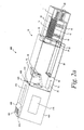
FIG. 2a is a top perspective view of the sensor-dispensing device according to an embodiment of the invention attached to the cartridge assembly ofFIG. 1 , where the gripping mechanism of the sensor-dispensing device is in a first position and the outer cartridge is in a first position; -
FIG. 2b is a top perspective view of the sensor-dispensing device according to an embodiment of the invention attached to the cartridge assembly ofFIG. 1 , where the gripping mechanism of the sensor-dispensing device is in the first position and the outer cartridge is in a second position; -
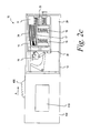
FIG. 2c is a front view of the sensor-dispensing device according to an embodiment of the invention attached to the cartridge assembly ofFIG. 1 , where the gripping mechanism of the sensor-dispensing device is in a second position and the outer cartridge is in the second position; -
FIG. 2d is a front view of the sensor-dispensing device according to an embodiment of the invention attached to the cartridge assembly ofFIG. 1 , showing the contacting of the sensor by the gripping mechanism; -
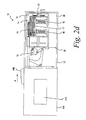
FIG. 3a is an enlarged top perspective view of the sensor-dispensing device according to an embodiment of the invention attached to the cartridge assembly ofFIG. 1 , showing the gripping and removal of the sensor through the outer cartridge (inner cartridge and end cap not shown); -
FIG. 3b is an front perspective view of the sensor-dispensing device according to an embodiment of the invention attached to the cartridge assembly ofFIG. 1 , showing the gripping and removal of the sensor through the outer cartridge (inner cartridge and end cap not shown); and -
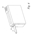
FIG. 4 is a top perspective view of the sensor-dispensing device ofFIG. 2a detached from the cartridge assembly. - While the invention is susceptible to various modifications and alternative forms, specific embodiments are shown by way of example in the drawings and are described in detail herein. It should be understood, however, that the invention is not intended to be limited to the particular forms disclosed. Rather, the invention is to cover all modifications, equivalents, and alternatives falling within the spirit and scope of the invention as defined by the appended claims.
- The present invention includes a disposable cartridge that contains a plurality of test sensors. The plurality of test sensors is used to determine concentrations of analytes. Analytes that may be measured using the present invention include glucose, lipid profiles (e.g., cholesterol, triglycerides, LDL and HDL), microalbumin, hemoglobin A1C, fructose, lactate, or bilirubin. The present invention is not limited, however, to these specific analytes and it is contemplated that other analyte concentrations may be determined. The analytes may be in, for example, a whole blood sample, a blood serum sample, a blood plasma sample, or other body fluids like ISF (interstitial fluid) and urine.
- Referring to the drawings, a
cartridge assembly 10 inFIG. 1 is shown that is adapted to be used in a sensor-dispensing device. Thecartridge assembly 10 is a substantially moisture-proof and air-tight device. Thecartridge assembly 10 ofFIG. 1 comprises adisposable cartridge 11 and anend cap 12. Thecartridge 11 comprises anouter cartridge 13 and aninner cartridge 15. The inner cartridge comprises a plurality oftest sensors 14 and amechanical mechanism 16. The end cap comprises at least onesealing mechanism 18. Thecartridge 11 is adapted to be disposable after each of the plurality oftest sensors 14 has been used. After each of the plurality oftest sensors 14 has been used, thecartridge 11 may be disassembled from theend cap 12 and replaced with a second cartridge that includes a plurality of unused test sensors. - Referring to
FIG. 1 , theouter cartridge 13 contains anopening 20 through which thetest sensors 14 exit thecartridge 11. In the closed, i.e., sealed position, theopening 20 is sealed using at least onesealing mechanism 18. Thesealing mechanism 18 prevents or inhibits air and moisture from entering into the interior of thecartridge 11 that contains a plurality oftest sensors 14 within theinner cartridge 15. Theopening 20 extends from theouter cartridge 13 to theinner cartridge 15. Theopening 20 is sized to allow the plurality oftest sensors 14 to move therethrough one at a time and eventually exit theinner cartridge 15 andouter cartridge 13. Specifically, the plurality oftest sensors 14, one at a time, exits theinner cartridge 15 andouter cartridge 13 via theopening 20. - The
sealing mechanism 18 contained within theend cap 12, comprises aseal door 19 that covers theopening 20 when the door is in the sealed position as shown inFIG. 1 . Theseal door 19 may rotate along an axis to permit the door to seal theopening 20 in cases where thedoor 19 may become misaligned with theopening 20 during operation. Thesealing mechanism 18 further comprises a linkage mechanism 21 that facilitates the movement of theseal door 19 during the sealing and unsealing of theopening 20. The linkage mechanism 21 comprises at least two fixed points, designated inFIG. 1 as 21a and 21b. The fixed points, 21a and 21b, maintain the linkage mechanism in place during the movement of theseal door 19. - The inner surface of the
outer cartridge 13 comprises one or more members, designated as 22 inFIG. 1 . Themembers 22 stop the movement of theinner cartridge 15 when they come into contact with its outer surface and prevent the further movement of theinner cartridge 15 in the direction of theopening 20. In addition, the space created between the inner cartridge and outer cartridge when themembers 22 contact the inner cartridge may be used tohouse desiccant material 26. - The
outer cartridge 13 comprises a holding mechanism or feature 24 that holds the upper most of the plurality ofsensors 14 from moving, when theinner cartridge 15 is in motion. As will be further discussed below, during the operation of the sensor-dispensing device, theinner cartridge 15 moves in the direction of theopening 20. During this movement, the holdingmechanism 24 contacts the upper most test sensor and holds the test sensor in place while the remainder of the stack ofsensors 14 moves with theinner cartridge 15. - The movement of the
inner cartridge 15 within theouter cartridge 13 is guided by aguiding mechanism 25. The guidingmechanism 25 ensures that theinner cartridge 15 moves in a linear fashion during the operation of the sensor-dispensing device. Thefeature 25 has a triangular profile that provides a linear motion for theinner cartridge 15. - As shown in
FIG. 1 , the plurality oftest sensors 14 is stacked within theinner cartridge 15. The plurality oftest sensors 14 is adapted to assist in testing at least one analyte. As discussed above, one of the analytes that may be tested is glucose from, for example, a whole blood sample. In one embodiment, the plurality oftest sensors 14 would include an appropriately selected enzyme to react with the desired analyte or analytes to be tested. An enzyme that may be used to react with glucose is glucose oxidase. It is contemplated that other enzymes may be used such as glucose dehydrogenase. An example of atest sensor 14 is disclosed inU.S. Patent No. 6,531,040 assigned to Bayer Corporation. It is contemplated that other test sensors may be used in thecartridge assembly 10. - The plurality of
test sensors 14 may vary in number than shown inFIG. 1 so as to address the needs of different users. Typically, the stacked test sensors contain from about 10 to about 100 sensors. Because of limited shelf- and use-life of the test sensors, it is envisioned that a user who tests infrequently would likely desire a cartridge having less test sensors compared to a user who tests more frequently. - To urge the stacked
test sensors 14 upwardly, amechanical mechanism 16 is used according to one embodiment. Themechanical mechanism 16 is located within theinner cartridge 15, and assists in positioning one of the plurality of test sensors for eventual ejection from thecartridge 11 viaopening 20. The mechanical mechanism is any device that can exert pressure on the stackedtest sensors 14 so as to position one of the plurality of test sensors for ejection. For example, themechanical mechanism 16 depicted inFIG. 1 is comprised of two springs and asensor pressure plate 17 that guides the stack of sensors in an upwardly manner. Various types of springs may be used as the mechanical mechanism to upwardly urge the stackedtest sensors 14. For example, the spring may be a compression spring or a torsion spring. Springs are desirable because of their simplicity and ease of use. Certain embodiments of the invention may have a single spring as part of themechanism 16, while others (like the one exemplified inFIG. 1 ) may have two springs as part of themechanism 16. - To assist in protecting the reagent(s) in the
test sensors 14, desirable packaging material and/or desiccant material may be used. Thedisposable cartridge 11 is typically packaged in material that prevents or inhibits air from entering into an interior of theinner cartridge 15 that contains thetest sensors 14. One type of removable packaging that may be used to enclose thedisposable cartridge 11 is aluminum foil. It is contemplated that other types of removable packaging may be employed. It is contemplated that desiccant material may be added in the interior of the removable packaging to assist in maintaining an appropriate humidity level therein. If the reagent in the test sensors is not humidity sensitive, then there is little or no need to include much, if any, desiccant. The removable packaging with or without the desiccant material assists in increasing the shelf-use of the test sensors. The removable packaging is to be removed before thecartridge 11 is attached to theend cap 12. - It is contemplated that the
disposable cartridge 11 may be initially placed in a polymeric container such as a bottle or other type of container. The container may be shaped similarly to the disposable cartridge with a desirable seal to prevent or inhibit air or moisture from entering the interior of the container. The container may include a lid that is attached to the remainder of the container via a living hinge. It is contemplated that desiccant may also be added within the container. The container with or without the desiccant material assists in increasing the shelf-use of the test sensors. Thedisposable cartridge 11 is removed from the container before being placed into the sensor-dispensing device. -
Desiccant material 26 is desirably added to thedisposable cartridge 11 to assist in maintaining an appropriate humidity level within the interior of theinner cartridge 15 that contains thetest sensors 14. In certain embodiments of the invention thedessicant material 26 may be added to the space between theouter cartridge 13 andinner cartridge 15 as exemplified inFIG. 1 . Specifically, some moisture may enter the interior of theouter cartridge 13 whenever theseal door 19 is opened and a sensor is pulled out from theinner cartridge 15, but such moisture is desirably absorbed by thedesiccant material 26 so as to protect the reagent in the test sensors from degradation. By maintaining an appropriate humidity level, reagent material in the test sensors is protected. The amount ofdesiccant material 26 should be sufficient to obtain the desired shelf-life (the time period before any of the plurality of test sensors are used). More specifically, the shelf-life typically refers to the time period before thecartridge 11 is removed from the packaging material, if used. The amount ofdesiccant material 26 should also be sufficient to obtain the desired use-life (the time period after first use of one of the plurality of test sensors). More specifically, the use-life typically refers to the time period after thecartridge 11 is removed from the packaging material, if used. - Examples of desiccant that may be included within the disposable container, the removable packaging enclosing the disposable container, or the container containing the
disposable cartridge 11 include commercially available desiccants. The desiccant may be in the form of several shapes including balls, tablets, granular, or paper. For example, the desiccant may be molecular sieve spheres or thick desiccant paper. A non-limiting example of desiccant material may be purchased from Multisorb of Buffalo, New York in the form of, for example, molecular sieve beads. In certain embodiments of the invention, the outer cartridge may be coated with desiccant or alternately could be made of a desiccant material. - It is contemplated that desiccant may not be used for test sensors that are not humidity sensitive. The amount of desiccant used, if any, depends on how humidity sensitive the test sensor is and the duration of the desired use-life.
- The
seal door 19 is adapted to move from a closed position (shown inFIG. 1 ) to an open position (shown inFIGS. 2a-2d andFIGS. 3a-3b ). In a closed position, theseal door 19 seals the interior of thecartridge 11 such that the environment and any moisture in it is prevented from contacting thetest sensors 14. In such a closed position, theseal door 19 provides a substantially moisture-proof and a substantially air-tight cartridge. Theseal door 19 is desirably designed to prevent or inhibit moisture from entering via theopening 20 and affecting the plurality oftest sensors 14 for at least the shelf-life and use-life of the plurality of sensors. When theseal door 19 is in an open position, thetest sensors 14, one at a time, can be moved through theopening 20 so as to eventually exit via theopening 20. - The
end cap 12 may be made of a variety of materials, but is typically made of polymeric material. Some examples of polymeric materials that may be used in forming theend cap 12 include polycarbonate, ABS, nylon, polystyrene, polypropylene, or combinations thereof. Other additives may be added in forming the housing such as, for example, TEFLON® for lubrication or glass to provide strength. It is contemplated that other additives may be employed. Polycarbonate is desirable for several reasons including being a durable material and having an ability to prevent or inhibit air (especially oxygen and moisture) from entering theend cap 12, which in turn can enter thecartridge 11 when theseal door 19 is opened. Additionally, if the outer cartridge is formed from two distinct sections, polycarbonate is capable of sealing to itself. This may be desirable in a process where the two cartridge sections are sonically welded. - The
end cap 12 may be formed by processes known to those skilled in the art including injection-molding processes. If injection-molding processes are used, the wall thicknesses are typically designed within normal ranges. It is contemplated that other processes may be used such as a molding process. - Referring to
FIG. 2a , a sensor-dispensingdevice 400 is depicted according to one embodiment. The sensor-dispensing device is used to determine concentrations of analytes. Analytes that may be measured using the present invention include glucose, lipid profiles (e.g., cholesterol, triglycerides, LDL and HDL), microalbumin, hemoglobin A1C, fructose, lactate, or bilirubin. The present invention is not limited, however, to these specific analytes and it is contemplated that other analyte concentrations may be determined. The analytes may be in, for example, a whole blood sample, a blood serum sample, a blood plasma sample, or other body fluids like ISF (interstitial fluid) and urine. - The sensor-dispensing
device 400 comprises acartridge assembly 10, a slidingassembly 402, anddevice housing 404. As shown inFIG. 2a , the slidingassembly 402 includes aslider 406 and agripping mechanism 408 attached to theslider 406. As shown inFIGS 2b-2d , thedevice housing 404 is adapted to receive thecartridge assembly 10. It is desirable for thecartridge assembly 10 to be removed from and loaded into thedevice housing 404 of the sensor-dispensingdevice 400 in a simple and easy manner. The device housing may comprise anLCD screen 410 that displays a reading that is proportional to the quantity of the particular analyte being measured. Thedevice housing 404 as shown inFIGs. 2a-2d loads thecartridge assembly 10 on to the end of thehousing 404 from which thegripping mechanism 408 extends towards thecartridge 11. Instead of being a side-loading device, the device housing may be a bottom-loading device. - It is contemplated that other cartridges and cartridge assemblies may be used. Depending on the shape of the cartridge to be used, the interior of the device housing may be redesigned to correspond to the shape of the cartridge.
- Referring to
FIG. 2a , theslider 406 is shown in a first position. By continuing to manually move theslider 406 in a forward direction (direction of arrow A inFIG. 2c ), theslider 406 is moved to a second position (seeFIG. 2d ). Theslider 406 inFIG. 2d is located closer to thecartridge assembly 10 than theslider 406 ofFIG. 2c . - The sliding
assembly 402 is adapted to grip one of the plurality oftest sensors 14 from theinner cartridge 15 and pull it at least partially through thesealing mechanism 18, such as shown inFIG. 3a . When theslider 406 is in the first position (FIGs. 2a ,b ), the gripping mechanism 408 (which is also in its first position inFIGs. 2a ,b ) does not contact any of the plurality oftest sensors 14 and is contained almost entirely with thehousing 404. As theslider 406 is moved in a forward direction (see direction of arrow A inFIG. 2c ), the gripping mechanism 408 (seeFIGs. 2c ,d ) is also moved in a forward direction. - Referring back to
FIG. 2a , the exterior of thehousing 404 forms anexternal channel 412 on the upper portion of thehousing 404. To facilitate easy movement of the slider, theslider 406 ofFIG. 2a is guided along the external channel 412 (seeFIG. 2c ). Theslider 406 is connected to the gripping mechanism via a connecting mechanism (not shown), such that the movement of theslider 406 is always accompanied by the movement of thegripping mechanism 408. To enable easier gripping by the user, theslider 406 may form ridges or serrations on a top surface thereof such as shown inFIGs. 2a ,b. - Referring back to
FIG. 2a , thegripping mechanism 408 is located in an internal channel 414 that assists in facilitating and guiding the movement and positioning of thegripping mechanism 408 from a first position (FIGs. 2a ,b ) to a second position (FIGs. 2c ,d andFIGs. 3a ,b ) and back to the first position. The slidingassembly 402 also includes a guidingblock 416 to further ensure that thegripping mechanism 408 is moving in a proper plane. The guidingblock 416 is located below theslider 406, and moves along the internal channel 414 with thegripping mechanism 408. In certain embodiments of the invention, the guidingblock 416 is the connecting mechanism by which theslider 406 is connected to thegripping mechanism 408. - According to one process, the
gripping mechanism 408 ofFIG. 2a extends through anopening 420 in the housing and then extends towards and contacts the linkage mechanism 21 (FIG. 1 ). Upon contacting the linkage mechanism 21, thegripping mechanism 408 extends further towards thecartridge opening 20. The contacting of the linkage mechanism 21 and the continued forward movement of thegripping mechanism 408 causes the movement of theseal door 19 so as to unseal the opening 20 (FIG. 2c ). Thegripping mechanism 408 continues to move through theopening 20 and subsequently contacts theinner cartridge 15. After contacting the inner cartridge, the gripping mechanism continues to move forward until it contacts one of the plurality of test sensors 14 (seeFIGs. 2c ,d ). - As shown in
FIG. 2a , a fixedgap 35 may exist between thestop member 30 and theopening 420. As explained further below, the stop member stops the forward movement of thecartridge 11 when the gripping mechanism grips and pulls a single sensor from the stack ofsensors 14 located within theinner cartridge 15. The fixedgap 35 provides a space for the test sensor after it has exited thecartridge 11. Another use for the fixedgap 35 is to provide a location for the placement of a lancet in the sensor-dispensingdevice 400. - The
opening 420 properly aligns thegripping mechanism 408 with respect to theseal 18, as well as one of the plurality oftest sensors 14. As theslider 406 is moved in a forward direction, thegripping mechanism 408 contacts and grips one of the plurality oftest sensors 14 throughseal 18. As theslider 406 is moved to the second position (seeFIGs. 2c ,d ), thegripping mechanism 408 continues to grip one of the plurality oftest sensors 14 that is held down in place by the holdingmechanism 24. After thegripping mechanism 408 has gripped one of the plurality oftest sensors 14, theslider 406 is moved back to the first position. As theslider 406 moves back to the first position, thegripping mechanism 408 continues to grip and pull one of the plurality oftest sensors 14 until the sensor has been separated from the stack of the plurality oftest sensors 14, and has at least partially passed through the seal 18 (seeFIGs. 3a ,b ). As thegripping mechanism 408 grips and pulls one of the plurality oftest sensors 14, theinner cartridge 15 comprising the stack of sensors begins to move towards the housing 404 (seeFIG. 2c ). The movement of thecartridge 11 towards thehousing 404 is stopped by thestop member 30 where it latches in place. When the forward movement of thecartridge 11 is stopped by thestop member 30, thegripping mechanism 408 separates the single sensor from the stack ofsensors 14. After theslider 406 has returned to the first position, thegripping mechanism 408 retains the sensor within its grasp and presents the sensor in a manner suitable for use by a user (seeFIG. 4 ). - The movement of the
inner cartridge 15 during the gripping and pulling oftest sensor 14, is stopped by thefeatures 22 on the inner surface of the outer cartridge, which prevent the inner cartridge wall from contacting the inner wall of the outer cartridge (seeFIG. 1 ). - In a certain embodiment of the invention, the
gripping mechanism 408 comprises electrical contacts that link thesensor 14 to the meter electronics (not shown) contained within thehousing 404. Thesensor 14 may be linked to the meter electronics via sliding contacts or via flexible circuit cables (not shown). -
FIG. 4 depicts thesensor dispensing device 400 in which thehousing 404 has been separated from thecartridge assembly 10. As shown inFIG. 4 , after asingle test sensor 14 has been separated and extracted from the plurality of test sensors located within theinner cartridge 15, theslider 406 is returned to the first position and thegripping mechanism 408 retains the sensor within its grasp and presents the sensor in a manner suitable for use by a user. - In certain embodiments of the invention, the sensor is presented in a sidewise orientation after extraction from the cartridge.
- The testing end of the sensor is adapted-to be placed into contact with the fluid sample (e.g., a whole blood sample) to be tested. The whole blood sample may be generated by a lancing device such as a lancet. The whole blood sample may be obtained by a lancet that may be separate from the sensor-dispensing device or may be integrated within the sensor-dispensing device. The lancing device may obtain blood by, e.g., pricking a person's finger.
- According to one process, the whole blood sample may be prepared for testing by (a) advancing one of the test sensors in position to receive a whole blood sample; (b) generating a whole blood sample; and (c) bringing the test sensor and the whole blood sample into contact wherein the blood is generally drawn into the sensor by capillary action.
- The sensors are typically provided with a capillary channel that extends from the front or testing end of the sensors to biosensing or reagent material disposed in the sensor. When the testing end of the sensor is placed into fluid (e.g., blood that is accumulated on a person's finger after the finger has been pricked), a portion of the fluid is drawn into the capillary channel by capillary action. The fluid then chemically reacts with the reagent material in the sensor so that an electrical signal indicative of the blood glucose level in the blood being tested is supplied and subsequently transmitted to an electrical assembly.
- After the testing has been completed, the test sensor may be removed by several methods from the
housing 404. In one embodiment, the sensor-dispensing device may include a eject mechanism that ejects the used test sensor from the sensor-dispensing device. In such an embodiment, the test sensor is released forcefully. In another embodiment, the test sensors may be ejected by releasing a grip of the test sensors, resulting in the test sensor being discarded by gravity from the sensor-dispensing device. In a further embodiment, the test sensor may also be removed manually from the sensor-dispensing device. - As shown in
FIGs. 3a ,b , thegripping mechanism 408 may extend through theopening 20 in the cartridge when being moved to the second position. In this extended position, thegripping mechanism 408 contacts and grips one of thetest sensors 14. - When the
slider 406 is moved in a backward direction (i.e., the opposite direction of arrow A shown inFIG. 2c ) from its second position to the first position ofFIG. 2a , thegripping mechanism 408 is simultaneously moved from its second position to the first position, resulting in thegripping mechanism 408 passing through theseal 18. While theslider 406 and thegripping mechanism 408 are in the first position, thecartridge 11 is substantially moisture-proof and air-tight. It is contemplated that the sensor-dispensing device may activate the slider mechanism automatically such as in response to pressing a button. - The
housing 404 and theslider 406 are typically made of a polymeric materials. Non-limiting examples of polymeric materials include polycarbonate, ABS, nylon, polypropylene, or combinations thereof. Additives may be added to the polymeric material that forms the slider. It is contemplated that the slider may be made of other materials such as metallic materials. - The
gripping mechanism 408 may be made of metal or polymeric material. Some non-limited metallic materials include stainless steel and bronze with appropriate plating. Non-limiting examples of polymeric materials include polycarbonate, ABS, nylon, polypropylene, or combinations thereof. Additives may be added to the polymeric material that forms the gripping mechanism. - The sensor-dispensing
device 400 typically includes a microprocessor or the like for processing and/or storing data generated during the blood glucose test procedure. This data may be displayed on aliquid crystal display 410 located on the surface of the housing 404 (seeFIG. 2a ). The liquid crystal display displays information from the testing procedure on the sensor-dispensingdevice 400. - Some of the information that may be displayed when the sensor-dispensing device is in use include the following: a battery indication, a numerical display, an indication of the number of sensors remaining, an indication to load a cartridge into the sensor-dispensing device, apply blood indication, a temperature indication, or various combinations thereof.
- The sensor-dispensing
device 400 may also contain an opening for a battery-tray assembly. The battery-tray assembly includes a battery-tray in which a battery is disposed. The battery-tray assembly is inserted into the opening in a side of the sensor-dispensingdevice 400. When so inserted, the battery provides power for the electronics within thedevice 400, including the circuitry on the circuit board assembly (not shown) and theliquid crystal display 410. - While the invention has been described with reference to details of the illustrated embodiment, these details are not intended to limit the scope of the invention as defined in the appended claims. For example, the sensor-dispensing
device 400 can be used for testing fluids other than blood glucose. In fact, the sensor-dispensingdevice 400 can be used in connection with the analysis of any type of chemistry fluid that can be analyzed by using a reagent material.
Claims (23)
- A sensor-dispensing device (400) adapted to determine an analyte concentration of a fluid, the device comprising:a cartridge assembly (10) including a disposable cartridge (11) and a sealing mechanism (18), the disposable cartridge comprising an outer cartridge (13) and an inner cartridge (15), the inner cartridge containing a plurality of sensors (14) arranged in a stack therein, the outer cartridge including a holding mechanism (24) that holds at least one of the sensors in place during movement of the inner cartridge, the sealing mechanism being adapted to form a substantially moisture-tight seal so as to protect the sensors within the inner cartridge from atmospheric moisture;characterised bya gripping mechanism (408) being moveable between a first position and a second position, the gripping mechanism including an engaging end with a slot configured to engage and grip the one of the sensors such that a portion of the one of the sensors is inside the slot in response to the gripping mechanism being in the second position, the gripping mechanism being configured to extend into an opening (20) in the outer cartridge and to pull the one of the sensors from the stack through the opening in the outer cartridge,wherein the outer cartridge forms an opening of sufficient dimensions to permit a sensor and the gripping mechanism to pass therethrough.
- The sensor-dispensing device of claim further comprising a mechanism for determining the analyte concentration in the fluid.
- The sensor-dispensing device of claim 1, wherein the gripping mechanism is reciprocally slidable between the first position and the second position.
- The sensor-dispensing device of claim 3, wherein the movement of the gripping mechanism from the first position to the second position causes the gripping mechanism to insert at least a portion thereof between a scaling surface and the sealing mechanism so as to break the seal and then to travel to an extent sufficient to permit a sensor to be urged to a position to contact the gripping mechanism and wherein the movement of the gripping mechanism from the second position to the first position pulls the sensor through the opening.
- The sensor-dispensing device of claim 4, wherein the gripping mechanism contacts both the sealing mechanism and an uppermost sensor in the stack when traveling from the first position to the second position.
- The sensor-dispensing device of claim 5, wherein the gripping mechanism is adapted to be manually urged between the first and second positions by a user.
- The sensor-dispensing device of claim 1, wherein the sealing mechanism is attached to an end cap (12).
- The sensor-dispensing device of claim 7, wherein the sealing mechanism includes a seal door and a linkage mechanism, the linkage mechanism assists in facilitating the movement of the seal door.
- The sensor-dispensing device of claim 1, wherein the dimensions of the opening permit only a single sensor at a time to be pulled therethrough.
- The sensor-dispensing device of claim 1, wherein the outer cartridge includes exactly one opening.
- The sensor-dispensing device of claim 1, wherein the holding mechanism holds the uppermost sensor in place while the inner cartridge is moved relative to the outer cartridge by the gripping mechanism.
- The sensor-dispensing device of claim 1, wherein the gripping mechanism contains electrical contacts to electrically couple the one of the sensors in the slot to electronics of the sensor-dispensing device.
- The sensor-dispensing device of claim 1, wherein, each of the plurality of sensors carries a reagent sufficient to produce a signal in response to the analyte concentration in the fluid.
- The sensor-dispensing device of claim 1 further including a mechanical mechanism for positioning the test sensors, one at a time, for removal from the inner cartridge.
- A method of operating a sensor-dispensing device (400), the sensor-dispensing device adapted to handle a sensor pack containing a plurality of sensors (14), the method comprising the acts of:providing a sensor-dispensing device including a cartridge assembly (10) and a gripping mechanism (408), the cartridge assembly including a disposable cartridge (11) and a sealing mechanism (18), the disposable cartridge comprising an outer cartridge (13) and an inner cartridge (15), the inner cartridge containing a plurality of sensors arranged in a stack therein, the outer cartridge including a holding mechanism (24) that holds at least one of the sensors in place during movement of the inner cartridge, the outer cartridge forming an opening (20) of sufficient dimensions to permit a sensor and the gripping mechanism to pass therethrough, the sealing mechanism being adapted to form a substantially moisture-tight seal so as to protect the sensors within the inner cartridge from atmospheric moisture; andadvancing the gripping mechanism from a first position to a second position so as to move the sealing mechanism to an open position and to contact one of the plurality of test sensors with an engaging end of the gripping mechanism, the engaging end of the gripping mechanism including a slot configured to engage and grip the one of the plurality of sensors such that a portion of the one of the plurality of sensors is inside the slot in response to the gripping mechanism being in the second position,pulling the test sensor via the gripping mechanism through the opening of the cartridge assembly,placing a fluid with an analytc on the test sensor; anddetermining the concentration of the analyte.
- The method of claim 15, wherein the analyte is glucose.
- The method of claim 15, wherein advancing the gripping mechanism includes reciprocally sliding the gripping mechanism between the first position and the second position.
- The method of claim 15, wherein the sealing mechanism is attached to an end cap.
- The method of claim 15, wherein the sealing mechanism includes a seal door (19) and a linkage mechanism (21), the linkage mechanism assists in facilitating the movement of the seal door.
- The method of claim 15, wherein the dimensions of the opening permit only a single sensor at a time to be pulled therethrough.
- The method of claim 15, wherein the outer cartridge includes exactly one opening.
- The method of claim 15, wherein the holding mechanism holds the uppermost sensor in place while the inner cartridge is moved relative to the outer cartridge by the gripping mechanism.
- The method of claim 15, wherein the gripping mechanism contains electrical contacts to electrically couple the at least one of the sensors in the slot to electronics of the sensor-dispensing device.
Applications Claiming Priority (2)
| Application Number | Priority Date | Filing Date | Title |
|---|---|---|---|
| US62083404P | 2004-10-21 | 2004-10-21 | |
| PCT/US2005/037364 WO2006047135A1 (en) | 2004-10-21 | 2005-10-19 | Sensor-dispensing device and mechanism for extracting sensor |
Publications (2)
| Publication Number | Publication Date |
|---|---|
| EP1851539A1 EP1851539A1 (en) | 2007-11-07 |
| EP1851539B1 true EP1851539B1 (en) | 2014-04-30 |
Family
ID=35613877
Family Applications (1)
| Application Number | Title | Priority Date | Filing Date |
|---|---|---|---|
| EP05808533.3A Not-in-force EP1851539B1 (en) | 2004-10-21 | 2005-10-19 | Sensor-dispensing device and method of operating it |
Country Status (11)
| Country | Link |
|---|---|
| US (1) | US8142733B2 (en) |
| EP (1) | EP1851539B1 (en) |
| JP (1) | JP2008518204A (en) |
| CN (1) | CN101061384A (en) |
| BR (1) | BRPI0516235A (en) |
| CA (1) | CA2584606A1 (en) |
| MX (1) | MX2007004756A (en) |
| NO (1) | NO20072572L (en) |
| RU (1) | RU2390023C2 (en) |
| TW (1) | TW200630610A (en) |
| WO (1) | WO2006047135A1 (en) |
Families Citing this family (84)
| Publication number | Priority date | Publication date | Assignee | Title |
|---|---|---|---|---|
| US6391005B1 (en) * | 1998-03-30 | 2002-05-21 | Agilent Technologies, Inc. | Apparatus and method for penetration with shaft having a sensor for sensing penetration depth |
| US8641644B2 (en) | 2000-11-21 | 2014-02-04 | Sanofi-Aventis Deutschland Gmbh | Blood testing apparatus having a rotatable cartridge with multiple lancing elements and testing means |
| US7981056B2 (en) | 2002-04-19 | 2011-07-19 | Pelikan Technologies, Inc. | Methods and apparatus for lancet actuation |
| DE60234598D1 (en) | 2001-06-12 | 2010-01-14 | Pelikan Technologies Inc | SELF-OPTIMIZING LANZET DEVICE WITH ADAPTANT FOR TEMPORAL FLUCTUATIONS OF SKIN PROPERTIES |
| ATE485766T1 (en) | 2001-06-12 | 2010-11-15 | Pelikan Technologies Inc | ELECTRICAL ACTUATING ELEMENT FOR A LANCET |
| US9226699B2 (en) | 2002-04-19 | 2016-01-05 | Sanofi-Aventis Deutschland Gmbh | Body fluid sampling module with a continuous compression tissue interface surface |
| US7749174B2 (en) | 2001-06-12 | 2010-07-06 | Pelikan Technologies, Inc. | Method and apparatus for lancet launching device intergrated onto a blood-sampling cartridge |
| US7025774B2 (en) | 2001-06-12 | 2006-04-11 | Pelikan Technologies, Inc. | Tissue penetration device |
| US8337419B2 (en) | 2002-04-19 | 2012-12-25 | Sanofi-Aventis Deutschland Gmbh | Tissue penetration device |
| US9795747B2 (en) | 2010-06-02 | 2017-10-24 | Sanofi-Aventis Deutschland Gmbh | Methods and apparatus for lancet actuation |
| US9427532B2 (en) | 2001-06-12 | 2016-08-30 | Sanofi-Aventis Deutschland Gmbh | Tissue penetration device |
| US7892183B2 (en) | 2002-04-19 | 2011-02-22 | Pelikan Technologies, Inc. | Method and apparatus for body fluid sampling and analyte sensing |
| US8360992B2 (en) | 2002-04-19 | 2013-01-29 | Sanofi-Aventis Deutschland Gmbh | Method and apparatus for penetrating tissue |
| US8579831B2 (en) | 2002-04-19 | 2013-11-12 | Sanofi-Aventis Deutschland Gmbh | Method and apparatus for penetrating tissue |
| US9248267B2 (en) | 2002-04-19 | 2016-02-02 | Sanofi-Aventis Deustchland Gmbh | Tissue penetration device |
| US8784335B2 (en) | 2002-04-19 | 2014-07-22 | Sanofi-Aventis Deutschland Gmbh | Body fluid sampling device with a capacitive sensor |
| US7491178B2 (en) | 2002-04-19 | 2009-02-17 | Pelikan Technologies, Inc. | Method and apparatus for penetrating tissue |
| US7175642B2 (en) | 2002-04-19 | 2007-02-13 | Pelikan Technologies, Inc. | Methods and apparatus for lancet actuation |
| US7547287B2 (en) * | 2002-04-19 | 2009-06-16 | Pelikan Technologies, Inc. | Method and apparatus for penetrating tissue |
| US9795334B2 (en) | 2002-04-19 | 2017-10-24 | Sanofi-Aventis Deutschland Gmbh | Method and apparatus for penetrating tissue |
| US7909778B2 (en) | 2002-04-19 | 2011-03-22 | Pelikan Technologies, Inc. | Method and apparatus for penetrating tissue |
| US7331931B2 (en) | 2002-04-19 | 2008-02-19 | Pelikan Technologies, Inc. | Method and apparatus for penetrating tissue |
| US7297122B2 (en) | 2002-04-19 | 2007-11-20 | Pelikan Technologies, Inc. | Method and apparatus for penetrating tissue |
| US8267870B2 (en) | 2002-04-19 | 2012-09-18 | Sanofi-Aventis Deutschland Gmbh | Method and apparatus for body fluid sampling with hybrid actuation |
| US7232451B2 (en) | 2002-04-19 | 2007-06-19 | Pelikan Technologies, Inc. | Method and apparatus for penetrating tissue |
| US7901362B2 (en) * | 2002-04-19 | 2011-03-08 | Pelikan Technologies, Inc. | Method and apparatus for penetrating tissue |
| US7648468B2 (en) * | 2002-04-19 | 2010-01-19 | Pelikon Technologies, Inc. | Method and apparatus for penetrating tissue |
| US9314194B2 (en) * | 2002-04-19 | 2016-04-19 | Sanofi-Aventis Deutschland Gmbh | Tissue penetration device |
| US7892185B2 (en) * | 2002-04-19 | 2011-02-22 | Pelikan Technologies, Inc. | Method and apparatus for body fluid sampling and analyte sensing |
| US7976476B2 (en) | 2002-04-19 | 2011-07-12 | Pelikan Technologies, Inc. | Device and method for variable speed lancet |
| US7674232B2 (en) | 2002-04-19 | 2010-03-09 | Pelikan Technologies, Inc. | Method and apparatus for penetrating tissue |
| US7226461B2 (en) | 2002-04-19 | 2007-06-05 | Pelikan Technologies, Inc. | Method and apparatus for a multi-use body fluid sampling device with sterility barrier release |
| US7229458B2 (en) | 2002-04-19 | 2007-06-12 | Pelikan Technologies, Inc. | Method and apparatus for penetrating tissue |
| US8221334B2 (en) | 2002-04-19 | 2012-07-17 | Sanofi-Aventis Deutschland Gmbh | Method and apparatus for penetrating tissue |
| US8702624B2 (en) | 2006-09-29 | 2014-04-22 | Sanofi-Aventis Deutschland Gmbh | Analyte measurement device with a single shot actuator |
| US8574895B2 (en) | 2002-12-30 | 2013-11-05 | Sanofi-Aventis Deutschland Gmbh | Method and apparatus using optical techniques to measure analyte levels |
| EP1620021A4 (en) * | 2003-05-02 | 2008-06-18 | Pelikan Technologies Inc | Method and apparatus for a tissue penetrating device user interface |
| EP1628567B1 (en) | 2003-05-30 | 2010-08-04 | Pelikan Technologies Inc. | Method and apparatus for fluid injection |
| DK1633235T3 (en) | 2003-06-06 | 2014-08-18 | Sanofi Aventis Deutschland | Apparatus for sampling body fluid and detecting analyte |
| WO2006001797A1 (en) | 2004-06-14 | 2006-01-05 | Pelikan Technologies, Inc. | Low pain penetrating |
| US8282576B2 (en) | 2003-09-29 | 2012-10-09 | Sanofi-Aventis Deutschland Gmbh | Method and apparatus for an improved sample capture device |
| EP1680014A4 (en) | 2003-10-14 | 2009-01-21 | Pelikan Technologies Inc | Method and apparatus for a variable user interface |
| US7822454B1 (en) | 2005-01-03 | 2010-10-26 | Pelikan Technologies, Inc. | Fluid sampling device with improved analyte detecting member configuration |
| EP1706026B1 (en) | 2003-12-31 | 2017-03-01 | Sanofi-Aventis Deutschland GmbH | Method and apparatus for improving fluidic flow and sample capture |
| US8828203B2 (en) | 2004-05-20 | 2014-09-09 | Sanofi-Aventis Deutschland Gmbh | Printable hydrogels for biosensors |
| US9775553B2 (en) | 2004-06-03 | 2017-10-03 | Sanofi-Aventis Deutschland Gmbh | Method and apparatus for a fluid sampling device |
| EP1765194A4 (en) | 2004-06-03 | 2010-09-29 | Pelikan Technologies Inc | Method and apparatus for a fluid sampling device |
| CA2584606A1 (en) | 2004-10-21 | 2006-05-04 | Bayer Healthcare Llc | Sensor-dispensing device and mechanism for extracting sensor |
| US20060167382A1 (en) * | 2004-12-30 | 2006-07-27 | Ajay Deshmukh | Method and apparatus for storing an analyte sampling and measurement device |
| US8652831B2 (en) * | 2004-12-30 | 2014-02-18 | Sanofi-Aventis Deutschland Gmbh | Method and apparatus for analyte measurement test time |
| EP1835848A4 (en) * | 2004-12-30 | 2009-07-29 | Pelikan Technologies Inc | Method and apparatus for analyte measurement test time |
| WO2006076721A2 (en) | 2005-01-14 | 2006-07-20 | Bayer Healthcare Llc | Test sensor cartridges and sensor-dispensing instruments |
| US8016154B2 (en) * | 2005-05-25 | 2011-09-13 | Lifescan, Inc. | Sensor dispenser device and method of use |
| DE602006017709D1 (en) * | 2005-07-14 | 2010-12-02 | Bayer Healthcare Llc | LANZET DEVICE FOR ONE SKIN POINT |
| US8865743B2 (en) | 2006-01-06 | 2014-10-21 | Acelrx Pharmaceuticals, Inc. | Small volume oral transmucosal dosage forms containing sufentanil for treatment of pain |
| US9289583B2 (en) * | 2006-01-06 | 2016-03-22 | Acelrx Pharmaceuticals, Inc. | Methods for administering small volume oral transmucosal dosage forms using a dispensing device |
| US8357114B2 (en) | 2006-01-06 | 2013-01-22 | Acelrx Pharmaceuticals, Inc. | Drug dispensing device with flexible push rod |
| US9066847B2 (en) | 2007-01-05 | 2015-06-30 | Aceirx Pharmaceuticals, Inc. | Storage and dispensing devices for administration of oral transmucosal dosage forms |
| US8753308B2 (en) | 2006-01-06 | 2014-06-17 | Acelrx Pharmaceuticals, Inc. | Methods for administering small volume oral transmucosal dosage forms using a dispensing device |
| US8202535B2 (en) | 2006-01-06 | 2012-06-19 | Acelrx Pharmaceuticals, Inc. | Small-volume oral transmucosal dosage forms |
| US8252329B2 (en) | 2007-01-05 | 2012-08-28 | Acelrx Pharmaceuticals, Inc. | Bioadhesive drug formulations for oral transmucosal delivery |
| EP1881322B8 (en) | 2006-07-18 | 2011-09-28 | Roche Diagnostics GmbH | Space-optimised portable measuring system |
| US20080217353A1 (en) * | 2007-03-06 | 2008-09-11 | Michael John Newman | Method of Dispensing A Test Strip |
| US9052305B2 (en) * | 2007-03-06 | 2015-06-09 | Lifescan, Inc. | Test strip dispenser |
| WO2008111933A1 (en) * | 2007-03-12 | 2008-09-18 | Bayer Healthcare Llc | Single-sensor meter system with no sensor handling and method of using the same |
| DE502007000369D1 (en) * | 2007-03-27 | 2009-02-26 | Roche Diagnostics Gmbh | Analyzer with replaceable test element magazine |
| US20090209883A1 (en) * | 2008-01-17 | 2009-08-20 | Michael Higgins | Tissue penetrating apparatus |
| WO2009126900A1 (en) * | 2008-04-11 | 2009-10-15 | Pelikan Technologies, Inc. | Method and apparatus for analyte detecting device |
| US9375169B2 (en) | 2009-01-30 | 2016-06-28 | Sanofi-Aventis Deutschland Gmbh | Cam drive for managing disposable penetrating member actions with a single motor and motor and control system |
| WO2010107761A1 (en) | 2009-03-18 | 2010-09-23 | Acelrx Pharmaceuticals, Inc. | Improved storage and dispensing devices for administration of oral transmucosal dosage forms |
| US20110182785A1 (en) * | 2010-01-22 | 2011-07-28 | Roche Diagnostics Operations, Inc. | Flat Pop-Up Primary Container And Methods of Manufacturing And Utilization Thereof |
| US8965476B2 (en) | 2010-04-16 | 2015-02-24 | Sanofi-Aventis Deutschland Gmbh | Tissue penetration device |
| WO2012138451A2 (en) * | 2011-04-08 | 2012-10-11 | Csp Technologies, Inc. | Strip dispenser and strips for use with the same |
| EP2618144A1 (en) * | 2012-01-18 | 2013-07-24 | Medical Device UG | Method and container for loading a measuring device with measuring units |
| US9075042B2 (en) | 2012-05-15 | 2015-07-07 | Wellstat Diagnostics, Llc | Diagnostic systems and cartridges |
| US9213043B2 (en) | 2012-05-15 | 2015-12-15 | Wellstat Diagnostics, Llc | Clinical diagnostic system including instrument and cartridge |
| US9625465B2 (en) | 2012-05-15 | 2017-04-18 | Defined Diagnostics, Llc | Clinical diagnostic systems |
| JP5823039B2 (en) * | 2012-06-11 | 2015-11-25 | パナソニックヘルスケアホールディングス株式会社 | Sensor storage container and sensor mounting method using the same |
| US10234414B2 (en) | 2014-05-13 | 2019-03-19 | Arkray, Inc. | Measurement apparatus, and method for operating measurement apparatus |
| JP6677452B2 (en) * | 2014-05-13 | 2020-04-08 | アークレイ株式会社 | measuring device |
| SG11201704797TA (en) | 2014-12-23 | 2017-07-28 | Acelrx Pharmaceuticals Inc | Systems, devices and methods for dispensing oral transmucosal dosage forms |
| ES2947769T3 (en) | 2015-10-30 | 2023-08-18 | Vertical Pharmaceuticals Llc | Apparatus and methods for dispensing oral transmucosal dosage forms |
| CN111053577A (en) * | 2018-01-05 | 2020-04-24 | 广州莲印医疗科技有限公司 | Fetal monitoring sensor management device |
| CN112758529B (en) * | 2020-12-24 | 2022-11-25 | 广州广电计量检测无锡有限公司 | Sample storage device |
Family Cites Families (64)
| Publication number | Priority date | Publication date | Assignee | Title |
|---|---|---|---|---|
| US3797488A (en) | 1972-07-10 | 1974-03-19 | Ampoules Inc | Ampoule applicator with one-way clutch |
| FR2508305B1 (en) | 1981-06-25 | 1986-04-11 | Slama Gerard | DEVICE FOR CAUSING A LITTLE BITE TO COLLECT A BLOOD DROP |
| US4449529A (en) | 1981-11-18 | 1984-05-22 | Becton Dickinson And Company | Automatic retractable lancet assembly |
| US4517978A (en) | 1983-01-13 | 1985-05-21 | Levin Paul D | Blood sampling instrument |
| US5279294A (en) | 1985-04-08 | 1994-01-18 | Cascade Medical, Inc. | Medical diagnostic system |
| US4627445A (en) | 1985-04-08 | 1986-12-09 | Garid, Inc. | Glucose medical monitoring system |
| US4787398A (en) | 1985-04-08 | 1988-11-29 | Garid, Inc. | Glucose medical monitoring system |
| US4735203A (en) | 1986-12-12 | 1988-04-05 | Ryder International Corporation | Retractable lancet |
| US4911344A (en) | 1988-03-23 | 1990-03-27 | Tek-Aids Inc. | Strip dispenser box |
| US4990154A (en) | 1989-06-19 | 1991-02-05 | Miles Inc. | Lancet assembly |
| US5196025A (en) | 1990-05-21 | 1993-03-23 | Ryder International Corporation | Lancet actuator with retractable mechanism |
| US5231993A (en) | 1991-11-20 | 1993-08-03 | Habley Medical Technology Corporation | Blood sampler and component tester with guide member |
| JP2572823Y2 (en) | 1992-02-13 | 1998-05-25 | 株式会社アドバンス | Simple blood sampler |
| US5244116A (en) | 1992-04-06 | 1993-09-14 | Leo Daniel W | Cosmetic sample dispenser with replaceable magazines |
| US5318583A (en) | 1992-05-05 | 1994-06-07 | Ryder International Corporation | Lancet actuator mechanism |
| US5267963A (en) | 1992-08-21 | 1993-12-07 | Nicholas Bachynsky | Medication injection device |
| US5304193A (en) | 1993-08-12 | 1994-04-19 | Sam Zhadanov | Blood lancing device |
| CA2135706C (en) | 1993-11-15 | 1999-06-15 | Walter E. Cover | Retractable-needle cannula insertion set with refinements to better control leakage, retraction speed, and reuse |
| US5350392A (en) | 1994-02-03 | 1994-09-27 | Miles Inc. | Lancing device with automatic cocking |
| US5527334A (en) | 1994-05-25 | 1996-06-18 | Ryder International Corporation | Disposable, retractable lancet |
| US5628764A (en) | 1995-03-21 | 1997-05-13 | Schraga; Steven | Collar lancet device |
| DE19604156A1 (en) | 1996-02-06 | 1997-08-07 | Boehringer Mannheim Gmbh | Skin cutting device for taking pain-free small amounts of blood |
| US5951492A (en) | 1996-05-17 | 1999-09-14 | Mercury Diagnostics, Inc. | Methods and apparatus for sampling and analyzing body fluid |
| EP0906062B1 (en) | 1996-05-17 | 2007-12-26 | Roche Diagnostics Operations, Inc. | Body fluid sampling device |
| US5951493A (en) | 1997-05-16 | 1999-09-14 | Mercury Diagnostics, Inc. | Methods and apparatus for expressing body fluid from an incision |
| US5741288A (en) | 1996-06-27 | 1998-04-21 | Chemtrak, Inc. | Re-armable single-user safety finger stick device having reset for multiple use by a single patient |
| US5693023A (en) | 1996-11-15 | 1997-12-02 | Adventec, Inc. | Syringe with retractable needle assembly |
| US6027459A (en) | 1996-12-06 | 2000-02-22 | Abbott Laboratories | Method and apparatus for obtaining blood for diagnostic tests |
| DE19715031A1 (en) | 1997-04-11 | 1998-10-15 | Boehringer Mannheim Gmbh | Magazine for storing test elements |
| US5916230A (en) | 1997-06-16 | 1999-06-29 | Bayer Corporation | Blood sampling device with adjustable end cap |
| US5954738A (en) | 1997-07-31 | 1999-09-21 | Bayer Corporation | Blood sampling device with lancet damping system |
| US5868772A (en) | 1997-07-31 | 1999-02-09 | Bayer Corporation | Blood sampling device with anti-twist lancet holder |
| US6090078A (en) | 1997-09-30 | 2000-07-18 | Becton, Dickinson And Company | Dampening devices and methods for needle retracting safety vascular access devices |
| US5971941A (en) | 1997-12-04 | 1999-10-26 | Hewlett-Packard Company | Integrated system and method for sampling blood and analysis |
| US6022366A (en) | 1998-06-11 | 2000-02-08 | Stat Medical Devices Inc. | Lancet having adjustable penetration depth |
| US6306152B1 (en) | 1999-03-08 | 2001-10-23 | Agilent Technologies, Inc. | Lancet device with skin movement control and ballistic preload |
| US6231531B1 (en) | 1999-04-09 | 2001-05-15 | Agilent Technologies, Inc. | Apparatus and method for minimizing pain perception |
| US6152942A (en) | 1999-06-14 | 2000-11-28 | Bayer Corporation | Vacuum assisted lancing device |
| SG85117A1 (en) | 1999-06-18 | 2001-12-19 | Surgilance Pte Ltd | Lancet assembly |
| DE19948759A1 (en) | 1999-10-09 | 2001-04-12 | Roche Diagnostics Gmbh | Blood lancet device for drawing blood for diagnostic purposes |
| CA2287757A1 (en) | 1999-10-29 | 2001-04-29 | Medical Plastic Devices M.P.D. Inc. | Disposable lancet |
| US6364889B1 (en) | 1999-11-17 | 2002-04-02 | Bayer Corporation | Electronic lancing device |
| KR200199396Y1 (en) | 2000-05-25 | 2000-10-02 | 이춘발 | Lancet with safety structure of blood collection needle |
| US6607543B2 (en) | 2000-06-13 | 2003-08-19 | Bayer Corporation | Lancing mechanism |
| DE10030410C1 (en) | 2000-06-21 | 2002-01-24 | Roche Diagnostics Gmbh | Blood lancet device for drawing blood for diagnostic purposes |
| US7138089B2 (en) | 2000-07-20 | 2006-11-21 | Hypoguard Limited | Test device for analyzing blood glucose or other analytes in bodily fluids |
| US6827899B2 (en) | 2000-08-30 | 2004-12-07 | Hypoguard Limited | Test device |
| TW495353B (en) | 2000-09-01 | 2002-07-21 | Bayer Ag | Adjustable endcap for lancing device |
| US6514270B1 (en) | 2000-11-10 | 2003-02-04 | Steven Schraga | Single use lancet device |
| US7063234B2 (en) | 2000-12-29 | 2006-06-20 | Csp Technologies, Inc. | Meter strip dispenser assembly |
| US7054758B2 (en) * | 2001-01-30 | 2006-05-30 | Sciona Limited | Computer-assisted means for assessing lifestyle risk factors |
| CN100339044C (en) | 2001-03-29 | 2007-09-26 | 因弗内斯医疗有限公司 | Integrated measuring apparatus for testing samples |
| US6997343B2 (en) | 2001-11-14 | 2006-02-14 | Hypoguard Limited | Sensor dispensing device |
| GB0127322D0 (en) | 2001-11-14 | 2002-01-02 | Hypoguard Ltd | Test device |
| US6908008B2 (en) | 2001-12-21 | 2005-06-21 | Lifescan, Inc. | Test device with means for storing and dispensing diagnostic strips |
| US20030186446A1 (en) | 2002-04-02 | 2003-10-02 | Jerry Pugh | Test strip containers and methods of using the same |
| GB2388898B (en) | 2002-04-02 | 2005-10-05 | Inverness Medical Ltd | Integrated sample testing meter |
| US7303726B2 (en) | 2002-05-09 | 2007-12-04 | Lifescan, Inc. | Minimal procedure analyte test system |
| US20030223906A1 (en) | 2002-06-03 | 2003-12-04 | Mcallister Devin | Test strip container system |
| DE50309876D1 (en) | 2002-10-29 | 2008-07-03 | Roche Diagnostics Gmbh | Test element analysis system |
| US7264139B2 (en) | 2003-01-14 | 2007-09-04 | Hypoguard Limited | Sensor dispensing device |
| US7582262B2 (en) * | 2004-06-18 | 2009-09-01 | Roche Diagnostics Operations, Inc. | Dispenser for flattened articles |
| CA2584606A1 (en) | 2004-10-21 | 2006-05-04 | Bayer Healthcare Llc | Sensor-dispensing device and mechanism for extracting sensor |
| CN101052881B (en) | 2004-10-29 | 2012-06-06 | 爱科来株式会社 | Analyzer, cartridge, and analysis kit |
-
2005
- 2005-10-19 CA CA002584606A patent/CA2584606A1/en not_active Abandoned
- 2005-10-19 MX MX2007004756A patent/MX2007004756A/en not_active Application Discontinuation
- 2005-10-19 EP EP05808533.3A patent/EP1851539B1/en not_active Not-in-force
- 2005-10-19 JP JP2007537960A patent/JP2008518204A/en not_active Withdrawn
- 2005-10-19 BR BRPI0516235-1A patent/BRPI0516235A/en not_active IP Right Cessation
- 2005-10-19 US US11/791,460 patent/US8142733B2/en active Active
- 2005-10-19 CN CNA2005800399576A patent/CN101061384A/en active Pending
- 2005-10-19 WO PCT/US2005/037364 patent/WO2006047135A1/en active Application Filing
- 2005-10-19 RU RU2007118685/14A patent/RU2390023C2/en not_active IP Right Cessation
- 2005-10-21 TW TW094137058A patent/TW200630610A/en unknown
-
2007
- 2007-05-21 NO NO20072572A patent/NO20072572L/en not_active Application Discontinuation
Also Published As
| Publication number | Publication date |
|---|---|
| NO20072572L (en) | 2007-07-17 |
| BRPI0516235A (en) | 2008-08-26 |
| CN101061384A (en) | 2007-10-24 |
| EP1851539A1 (en) | 2007-11-07 |
| US20080021296A1 (en) | 2008-01-24 |
| TW200630610A (en) | 2006-09-01 |
| MX2007004756A (en) | 2007-06-25 |
| RU2390023C2 (en) | 2010-05-20 |
| WO2006047135A1 (en) | 2006-05-04 |
| JP2008518204A (en) | 2008-05-29 |
| CA2584606A1 (en) | 2006-05-04 |
| RU2007118685A (en) | 2008-11-27 |
| US8142733B2 (en) | 2012-03-27 |
Similar Documents
| Publication | Publication Date | Title |
|---|---|---|
| EP1851539B1 (en) | Sensor-dispensing device and method of operating it | |
| US11391721B2 (en) | Test sensor cartridges and sensor-dispensing instruments | |
| US9448224B2 (en) | Cartridge and sensor-dispensing instrument | |
| US8231548B2 (en) | Portable measuring system having a moisture-proof assembly space | |
| JP2003139777A (en) | Packaging system for test sensor | |
| US9097699B2 (en) | Sensor storage and delivery system where the test sensors are individually foiled and arranged in a stack | |
| US20100178703A1 (en) | Single-sensor meter system with no sensor handling and method of using the same | |
| CN106574921B (en) | Sensor clip for stacked sensor dispensing system and system using same |
Legal Events
| Date | Code | Title | Description |
|---|---|---|---|
| PUAI | Public reference made under article 153(3) epc to a published international application that has entered the european phase |
Free format text: ORIGINAL CODE: 0009012 |
|
| 17P | Request for examination filed |
Effective date: 20070913 |
|
| AK | Designated contracting states |
Kind code of ref document: A1 Designated state(s): AT BE BG CH CY CZ DE DK EE ES FI FR GB GR HU IE IS IT LI LT LU LV MC NL PL PT RO SE SI SK TR |
|
| DAX | Request for extension of the european patent (deleted) | ||
| 17Q | First examination report despatched |
Effective date: 20110929 |
|
| GRAP | Despatch of communication of intention to grant a patent |
Free format text: ORIGINAL CODE: EPIDOSNIGR1 |
|
| RAP1 | Party data changed (applicant data changed or rights of an application transferred) |
Owner name: BAYER HEALTHCARE LLC |
|
| INTG | Intention to grant announced |
Effective date: 20131202 |
|
| GRAS | Grant fee paid |
Free format text: ORIGINAL CODE: EPIDOSNIGR3 |
|
| GRAA | (expected) grant |
Free format text: ORIGINAL CODE: 0009210 |
|
| AK | Designated contracting states |
Kind code of ref document: B1 Designated state(s): AT BE BG CH CY CZ DE DK EE ES FI FR GB GR HU IE IS IT LI LT LU LV MC NL PL PT RO SE SI SK TR |
|
| REG | Reference to a national code |
Ref country code: GB Ref legal event code: FG4D Ref country code: CH Ref legal event code: EP |
|
| REG | Reference to a national code |
Ref country code: AT Ref legal event code: REF Ref document number: 665460 Country of ref document: AT Kind code of ref document: T Effective date: 20140515 |
|
| REG | Reference to a national code |
Ref country code: IE Ref legal event code: FG4D |
|
| REG | Reference to a national code |
Ref country code: DE Ref legal event code: R096 Ref document number: 602005043476 Country of ref document: DE Effective date: 20140618 |
|
| REG | Reference to a national code |
Ref country code: AT Ref legal event code: MK05 Ref document number: 665460 Country of ref document: AT Kind code of ref document: T Effective date: 20140430 |
|
| REG | Reference to a national code |
Ref country code: LT Ref legal event code: MG4D |
|
| REG | Reference to a national code |
Ref country code: NL Ref legal event code: VDEP Effective date: 20140430 |
|
| PG25 | Lapsed in a contracting state [announced via postgrant information from national office to epo] |
Ref country code: CY Free format text: LAPSE BECAUSE OF FAILURE TO SUBMIT A TRANSLATION OF THE DESCRIPTION OR TO PAY THE FEE WITHIN THE PRESCRIBED TIME-LIMIT Effective date: 20140430 Ref country code: LT Free format text: LAPSE BECAUSE OF FAILURE TO SUBMIT A TRANSLATION OF THE DESCRIPTION OR TO PAY THE FEE WITHIN THE PRESCRIBED TIME-LIMIT Effective date: 20140430 Ref country code: NL Free format text: LAPSE BECAUSE OF FAILURE TO SUBMIT A TRANSLATION OF THE DESCRIPTION OR TO PAY THE FEE WITHIN THE PRESCRIBED TIME-LIMIT Effective date: 20140430 Ref country code: BG Free format text: LAPSE BECAUSE OF FAILURE TO SUBMIT A TRANSLATION OF THE DESCRIPTION OR TO PAY THE FEE WITHIN THE PRESCRIBED TIME-LIMIT Effective date: 20140730 Ref country code: GR Free format text: LAPSE BECAUSE OF FAILURE TO SUBMIT A TRANSLATION OF THE DESCRIPTION OR TO PAY THE FEE WITHIN THE PRESCRIBED TIME-LIMIT Effective date: 20140731 Ref country code: IS Free format text: LAPSE BECAUSE OF FAILURE TO SUBMIT A TRANSLATION OF THE DESCRIPTION OR TO PAY THE FEE WITHIN THE PRESCRIBED TIME-LIMIT Effective date: 20140830 Ref country code: FI Free format text: LAPSE BECAUSE OF FAILURE TO SUBMIT A TRANSLATION OF THE DESCRIPTION OR TO PAY THE FEE WITHIN THE PRESCRIBED TIME-LIMIT Effective date: 20140430 |
|
| PG25 | Lapsed in a contracting state [announced via postgrant information from national office to epo] |
Ref country code: AT Free format text: LAPSE BECAUSE OF FAILURE TO SUBMIT A TRANSLATION OF THE DESCRIPTION OR TO PAY THE FEE WITHIN THE PRESCRIBED TIME-LIMIT Effective date: 20140430 Ref country code: LV Free format text: LAPSE BECAUSE OF FAILURE TO SUBMIT A TRANSLATION OF THE DESCRIPTION OR TO PAY THE FEE WITHIN THE PRESCRIBED TIME-LIMIT Effective date: 20140430 Ref country code: PL Free format text: LAPSE BECAUSE OF FAILURE TO SUBMIT A TRANSLATION OF THE DESCRIPTION OR TO PAY THE FEE WITHIN THE PRESCRIBED TIME-LIMIT Effective date: 20140430 Ref country code: ES Free format text: LAPSE BECAUSE OF FAILURE TO SUBMIT A TRANSLATION OF THE DESCRIPTION OR TO PAY THE FEE WITHIN THE PRESCRIBED TIME-LIMIT Effective date: 20140430 Ref country code: SE Free format text: LAPSE BECAUSE OF FAILURE TO SUBMIT A TRANSLATION OF THE DESCRIPTION OR TO PAY THE FEE WITHIN THE PRESCRIBED TIME-LIMIT Effective date: 20140430 |
|
| PG25 | Lapsed in a contracting state [announced via postgrant information from national office to epo] |
Ref country code: PT Free format text: LAPSE BECAUSE OF FAILURE TO SUBMIT A TRANSLATION OF THE DESCRIPTION OR TO PAY THE FEE WITHIN THE PRESCRIBED TIME-LIMIT Effective date: 20140901 |
|
| PG25 | Lapsed in a contracting state [announced via postgrant information from national office to epo] |
Ref country code: CZ Free format text: LAPSE BECAUSE OF FAILURE TO SUBMIT A TRANSLATION OF THE DESCRIPTION OR TO PAY THE FEE WITHIN THE PRESCRIBED TIME-LIMIT Effective date: 20140430 Ref country code: DK Free format text: LAPSE BECAUSE OF FAILURE TO SUBMIT A TRANSLATION OF THE DESCRIPTION OR TO PAY THE FEE WITHIN THE PRESCRIBED TIME-LIMIT Effective date: 20140430 Ref country code: RO Free format text: LAPSE BECAUSE OF FAILURE TO SUBMIT A TRANSLATION OF THE DESCRIPTION OR TO PAY THE FEE WITHIN THE PRESCRIBED TIME-LIMIT Effective date: 20140430 Ref country code: SK Free format text: LAPSE BECAUSE OF FAILURE TO SUBMIT A TRANSLATION OF THE DESCRIPTION OR TO PAY THE FEE WITHIN THE PRESCRIBED TIME-LIMIT Effective date: 20140430 Ref country code: EE Free format text: LAPSE BECAUSE OF FAILURE TO SUBMIT A TRANSLATION OF THE DESCRIPTION OR TO PAY THE FEE WITHIN THE PRESCRIBED TIME-LIMIT Effective date: 20140430 Ref country code: BE Free format text: LAPSE BECAUSE OF FAILURE TO SUBMIT A TRANSLATION OF THE DESCRIPTION OR TO PAY THE FEE WITHIN THE PRESCRIBED TIME-LIMIT Effective date: 20140430 |
|
| REG | Reference to a national code |
Ref country code: DE Ref legal event code: R097 Ref document number: 602005043476 Country of ref document: DE |
|
| PLBE | No opposition filed within time limit |
Free format text: ORIGINAL CODE: 0009261 |
|
| STAA | Information on the status of an ep patent application or granted ep patent |
Free format text: STATUS: NO OPPOSITION FILED WITHIN TIME LIMIT |
|
| PG25 | Lapsed in a contracting state [announced via postgrant information from national office to epo] |
Ref country code: IT Free format text: LAPSE BECAUSE OF FAILURE TO SUBMIT A TRANSLATION OF THE DESCRIPTION OR TO PAY THE FEE WITHIN THE PRESCRIBED TIME-LIMIT Effective date: 20140430 |
|
| 26N | No opposition filed |
Effective date: 20150202 |
|
| REG | Reference to a national code |
Ref country code: DE Ref legal event code: R097 Ref document number: 602005043476 Country of ref document: DE Effective date: 20150202 |
|
| PG25 | Lapsed in a contracting state [announced via postgrant information from national office to epo] |
Ref country code: LU Free format text: LAPSE BECAUSE OF FAILURE TO SUBMIT A TRANSLATION OF THE DESCRIPTION OR TO PAY THE FEE WITHIN THE PRESCRIBED TIME-LIMIT Effective date: 20141019 Ref country code: MC Free format text: LAPSE BECAUSE OF FAILURE TO SUBMIT A TRANSLATION OF THE DESCRIPTION OR TO PAY THE FEE WITHIN THE PRESCRIBED TIME-LIMIT Effective date: 20140430 |
|
| REG | Reference to a national code |
Ref country code: CH Ref legal event code: PL |
|
| GBPC | Gb: european patent ceased through non-payment of renewal fee |
Effective date: 20141019 |
|
| REG | Reference to a national code |
Ref country code: IE Ref legal event code: MM4A |
|
| PG25 | Lapsed in a contracting state [announced via postgrant information from national office to epo] |
Ref country code: CH Free format text: LAPSE BECAUSE OF NON-PAYMENT OF DUE FEES Effective date: 20141031 Ref country code: LI Free format text: LAPSE BECAUSE OF NON-PAYMENT OF DUE FEES Effective date: 20141031 Ref country code: GB Free format text: LAPSE BECAUSE OF NON-PAYMENT OF DUE FEES Effective date: 20141019 Ref country code: SI Free format text: LAPSE BECAUSE OF FAILURE TO SUBMIT A TRANSLATION OF THE DESCRIPTION OR TO PAY THE FEE WITHIN THE PRESCRIBED TIME-LIMIT Effective date: 20140430 |
|
| REG | Reference to a national code |
Ref country code: FR Ref legal event code: ST Effective date: 20150630 |
|
| PG25 | Lapsed in a contracting state [announced via postgrant information from national office to epo] |
Ref country code: FR Free format text: LAPSE BECAUSE OF NON-PAYMENT OF DUE FEES Effective date: 20141031 |
|
| PG25 | Lapsed in a contracting state [announced via postgrant information from national office to epo] |
Ref country code: IE Free format text: LAPSE BECAUSE OF NON-PAYMENT OF DUE FEES Effective date: 20141019 |
|
| PG25 | Lapsed in a contracting state [announced via postgrant information from national office to epo] |
Ref country code: HU Free format text: LAPSE BECAUSE OF FAILURE TO SUBMIT A TRANSLATION OF THE DESCRIPTION OR TO PAY THE FEE WITHIN THE PRESCRIBED TIME-LIMIT; INVALID AB INITIO Effective date: 20051019 Ref country code: TR Free format text: LAPSE BECAUSE OF FAILURE TO SUBMIT A TRANSLATION OF THE DESCRIPTION OR TO PAY THE FEE WITHIN THE PRESCRIBED TIME-LIMIT Effective date: 20140430 |
|
| PGFP | Annual fee paid to national office [announced via postgrant information from national office to epo] |
Ref country code: DE Payment date: 20191029 Year of fee payment: 15 |
|
| REG | Reference to a national code |
Ref country code: DE Ref legal event code: R119 Ref document number: 602005043476 Country of ref document: DE |
|
| PG25 | Lapsed in a contracting state [announced via postgrant information from national office to epo] |
Ref country code: DE Free format text: LAPSE BECAUSE OF NON-PAYMENT OF DUE FEES Effective date: 20210501 |
|
| P01 | Opt-out of the competence of the unified patent court (upc) registered |
Effective date: 20230526 |