JP2008518204A - Sensor-dispensing device and mechanism for pulling out the sensor - Google Patents
Sensor-dispensing device and mechanism for pulling out the sensor Download PDFInfo
- Publication number
- JP2008518204A JP2008518204A JP2007537960A JP2007537960A JP2008518204A JP 2008518204 A JP2008518204 A JP 2008518204A JP 2007537960 A JP2007537960 A JP 2007537960A JP 2007537960 A JP2007537960 A JP 2007537960A JP 2008518204 A JP2008518204 A JP 2008518204A
- Authority
- JP
- Japan
- Prior art keywords
- sensor
- cartridge
- dispensing device
- opening
- gripping mechanism
- Prior art date
- Legal status (The legal status is an assumption and is not a legal conclusion. Google has not performed a legal analysis and makes no representation as to the accuracy of the status listed.)
- Withdrawn
Links
Images


Classifications
-
- G—PHYSICS
- G01—MEASURING; TESTING
- G01N—INVESTIGATING OR ANALYSING MATERIALS BY DETERMINING THEIR CHEMICAL OR PHYSICAL PROPERTIES
- G01N33/00—Investigating or analysing materials by specific methods not covered by groups G01N1/00 - G01N31/00
- G01N33/48—Biological material, e.g. blood, urine; Haemocytometers
- G01N33/483—Physical analysis of biological material
- G01N33/487—Physical analysis of biological material of liquid biological material
- G01N33/4875—Details of handling test elements, e.g. dispensing or storage, not specific to a particular test method
- G01N33/48757—Test elements dispensed from a stack
Landscapes
- Health & Medical Sciences (AREA)
- Engineering & Computer Science (AREA)
- Life Sciences & Earth Sciences (AREA)
- Biomedical Technology (AREA)
- Physics & Mathematics (AREA)
- Chemical & Material Sciences (AREA)
- Biochemistry (AREA)
- Optics & Photonics (AREA)
- Biophysics (AREA)
- Urology & Nephrology (AREA)
- General Health & Medical Sciences (AREA)
- Food Science & Technology (AREA)
- Medicinal Chemistry (AREA)
- General Physics & Mathematics (AREA)
- Molecular Biology (AREA)
- Hematology (AREA)
- Analytical Chemistry (AREA)
- Immunology (AREA)
- Pathology (AREA)
- Investigating Or Analysing Biological Materials (AREA)
- Automatic Analysis And Handling Materials Therefor (AREA)
- Measurement Of The Respiration, Hearing Ability, Form, And Blood Characteristics Of Living Organisms (AREA)
- Investigating Or Analysing Materials By The Use Of Chemical Reactions (AREA)
Abstract
【課題】
【解決手段】カートリッジ組立体は、センサ−分与装置にて使用し得るようにされている。カートリッジ組立体は、端部キャップと、使い捨て型カートリッジと、密封機構とを備えている。端部キャップは1つの開口部を有する。使い捨て型カートリッジは、外側カートリッジと、内側カートリッジとを備えている。内側カートリッジは、その内部に積層体にて配置されたセンサを保持している。センサの各々が流体中の分析物質の濃度に応答して信号を発生させるのに十分な試薬を保持している。外側カートリッジは、センサが開口部を貫通して通るのを許容するのに十分な寸法の開口部を形成する。外側カートリッジは、内側カートリッジが動く間、少なくとも1つのセンサをその位置に保持する保持機構を有する。密封機構は、内側カートリッジ内のセンサを雰囲気の湿気から保護し得るよう実質的に湿気不浸透性であるシールを形成し得るようにされている。【Task】
The cartridge assembly is adapted for use in a sensor-dispensing device. The cartridge assembly includes an end cap, a disposable cartridge, and a sealing mechanism. The end cap has one opening. The disposable cartridge includes an outer cartridge and an inner cartridge. The inner cartridge holds a sensor arranged in a laminated body therein. Each of the sensors holds sufficient reagent to generate a signal in response to the concentration of the analyte in the fluid. The outer cartridge forms an opening dimensioned enough to allow the sensor to pass through the opening. The outer cartridge has a holding mechanism that holds at least one sensor in position while the inner cartridge moves. The sealing mechanism is adapted to form a seal that is substantially moisture impervious to protect the sensor in the inner cartridge from ambient moisture.
Description
本発明は、全体として、センサ−分与装置と、試験センサを装置から引き出す機構とに関する。 The present invention generally relates to a sensor-dispensing device and a mechanism for withdrawing a test sensor from the device.
体液中の分析物質を定量的に測定することは、特定の生理学的異常を診断し且つ、修復する上で極めて重要である。例えば、乳酸塩、コレステロール及びビリルビンを特定の個人にて監視しなければならない。更に、体液中のグルコースを測定することは、その食事のグルコース摂取量を調節するためその体液中の血糖レベルを定期的にチェックしなければならない糖尿病の人にとって重要である。本明細書の開示のその他の部分は、グルコースの測定を対象とするが、本発明の方法は、適宜な酵素を選択するときその他の分析物質を測定すべく使用することが可能であることを理解すべきである。 Quantitatively measuring analytes in body fluids is extremely important in diagnosing and repairing certain physiological abnormalities. For example, lactate, cholesterol and bilirubin must be monitored in certain individuals. Furthermore, measuring glucose in body fluids is important for diabetics who must regularly check the blood sugar levels in the body fluids to regulate the glucose intake of the diet. While the rest of the disclosure herein is directed to measuring glucose, it should be noted that the method of the present invention can be used to measure other analytes when selecting the appropriate enzyme. Should be understood.
かかる試験の結果を使用して、投与すべきインスリン(存在するならば)又はその他の医薬の必要量を判断することができる。1つの型式の血糖の試験システムにおいて、血液試料を試験するため試験センサが使用される。 The results of such tests can be used to determine the required amount of insulin (if present) or other medicament to be administered. In one type of blood glucose test system, a test sensor is used to test a blood sample.
試験センサは、典型的に、血糖と反応するバイオセンシング又は試薬材料を保持している。センサの試験端は、例えば、人間の指を突き刺した後、その指に集まった血液のような試験すべき流体中に配置し得るようにされている。流体は、試験端から試薬材料まで毛管作用によってセンサ内を伸びる毛管通路内に導入され、試験すべき十分な量の流体がセンサ内に吸引されるようにする。その後、流体は、試験センサ内の試薬材料と化学的に反応する。電気化学的作用によって発生された電流は、試験される流体中の分析物質のレベルを表示する測定値に変換される。 Test sensors typically hold biosensing or reagent material that reacts with blood glucose. The test end of the sensor can be placed in a fluid to be tested, such as blood collected on a finger after it has been pierced, for example. Fluid is introduced into the capillary passage that extends through the sensor by capillary action from the test end to the reagent material, so that a sufficient amount of fluid to be tested is aspirated into the sensor. The fluid then chemically reacts with the reagent material in the test sensor. The current generated by the electrochemical action is converted into a measurement that indicates the level of analyte in the fluid being tested.
試験センサ接点にて発生された電気信号を監視装置に結合するため、センサ端を試験される流体中に配置する前に、センサをセンサホルダ内に挿入する必要がある。該ホルダは、センサがホルダ内に適正に挿入されたとき、試験センサの接点と結合される相応する合わさり接点を有する。その結果、ホルダは、試験センサと監視装置との間にて試験結果を集め且つ(又は)分析する境界面として作用する。 In order to couple the electrical signal generated at the test sensor contact to the monitoring device, the sensor must be inserted into the sensor holder before the sensor end is placed in the fluid to be tested. The holder has a corresponding mating contact that is coupled with the contact of the test sensor when the sensor is properly inserted into the holder. As a result, the holder acts as an interface for collecting and / or analyzing test results between the test sensor and the monitoring device.
殆どの試験センサは、センサ内にて試薬材料の一体性を保証し得るよう使用される前に、適宜な湿度レベルに維持する必要がある。試験センサは、個別に引き裂きパッケージ内に包装し、これらの試験センサを適宜な湿度レベルに維持することができるようにする。例えば、ブリスター型包装方法を使用することができる。この点に関して、包装物は、包装物内にて適正な湿度を維持すべく乾燥剤材料を含むことができる。一人の人が分析物質を試験すべく個々の試験センサを使用するため、シールを引き裂くことによって包装物を開放することができる。これと代替的に、一部の包装物は、ユーザが包装物の一側部に力を加えることを必要とし、その結果、試験センサが反対側部の箔を破断させ又は引き裂くことになる。理解し得るように、これらの包装物を開放することは難しくなる可能性がある。更に、包装物が開放されたならば、ユーザは、試験センサがセンサホルダに配置され、また、流体試料を試験すべく使用されるとき、試験センサが損傷され又は汚染されないことを保証する必要がある。 Most test sensors need to be maintained at an appropriate humidity level before being used to ensure the integrity of the reagent material within the sensor. The test sensors are individually packaged in a tear package so that these test sensors can be maintained at an appropriate humidity level. For example, a blister type packaging method can be used. In this regard, the package can include a desiccant material to maintain proper humidity within the package. Since one person uses individual test sensors to test the analyte, the package can be opened by tearing the seal. Alternatively, some packages require the user to apply a force to one side of the package, which results in the test sensor breaking or tearing the foil on the opposite side. As can be appreciated, opening these packages can be difficult. Furthermore, once the package is opened, the user must ensure that the test sensor is not damaged or contaminated when the test sensor is placed in the sensor holder and used to test the fluid sample. is there.
特定のセンサ−分与装置において、使い捨て型試験センサの積層体がカートリッジ内に提供され、その積層体は、試験が行われる試験ステーションに向けて押し又は付勢する。押し機構がカートリッジの一端の第一の開口部内に挿入され、該機構は、開口部を通してセンサの積層体と接触する。典型的に、押し機構は、積層体中の最頂部センサを通常、カートリッジの他端に配置された第二の開口部を通って第一の開口部から試験ステーションに向けて動かす。このため、押し機構を使用することは、カートリッジに2つの開口部が存在することを必要とする。2つの開口部を有するカートリッジは、カートリッジ内の残るセンサの貯蔵寿命を維持するため、カートリッジの密封に伴う問題点を招来する可能性がある。 In certain sensor-dispensing devices, a stack of disposable test sensors is provided in the cartridge, and the stack is pushed or biased toward the test station where the test is performed. A push mechanism is inserted into the first opening at one end of the cartridge, and the mechanism contacts the sensor stack through the opening. Typically, the push mechanism moves the top sensor in the stack, usually from the first opening toward the test station, through a second opening located at the other end of the cartridge. For this reason, using a push mechanism requires that the cartridge have two openings. A cartridge having two openings can introduce problems with cartridge sealing in order to maintain the shelf life of the remaining sensors in the cartridge.
一部のセンサ−分与装置において、センサを試験センサの積層体から動かす機構は、センサの積層体を収容する使い捨て型カートリッジ内に配置される。換言すれば、空のカートリッジが廃棄される毎に、センサを動かす機構も廃棄され、これによりカートリッジの交換コストを増大させることになる。 In some sensor-dispensing devices, a mechanism for moving the sensor from the test sensor stack is located in a disposable cartridge that houses the sensor stack. In other words, each time an empty cartridge is discarded, the mechanism for moving the sensor is also discarded, which increases the cost of cartridge replacement.
使い捨て型カートリッジを使用する一部のセンサ分与装置において、センサをカートリッジ内にて密封し且つ、センサをカートリッジから除去することを許容する機構は、カートリッジに物理的に取り付けられる設計とされている。このため、カートリッジにセンサが無くなり、従って交換しなければならない毎に、密封機構も交換しなければならず、このためカートリッジの交換コストを増大させることになる。 In some sensor dispensing devices that use disposable cartridges, the mechanism that seals the sensor within the cartridge and allows the sensor to be removed from the cartridge is designed to be physically attached to the cartridge. . For this reason, each time the cartridge has no sensor and therefore must be replaced, the sealing mechanism must also be replaced, which increases the cost of cartridge replacement.
従って、上述した問題点を解決する、センサ−分与装置と、センサを引き出す機構とを有することが望ましいであろう。
1つの実施の形態に従い、センサ−分与装置は、流体の分析物質の濃度を測定し得るようにされている。該装置は、カートリッジ組立体と、把持機構とを備えている。カートリッジ組立体は、端部キャップと、使い捨て型カートリッジと、密封機構とを有する。使い捨て型カートリッジは、外側カートリッジと、内側カートリッジとを備えている。内側カートリッジは、その内部にて積層体に配置された複数のセンサを保持している。外側カートリッジは、内側カートリッジが動く間、少なくとも1つのセンサをその位置に保持する保持機構を有する。密封機構は、センサを内側カートリッジ内にて雰囲気水分から保護し得るよう実質的に湿気不浸透性であるシールを形成し得るようにされている。把持機構は、センサを把持し且つ、センサを外側カートリッジの開口部を通して積層体から分与位置まで引っ張り得るようにされている。外側カートリッジは、センサ及び把持機構が貫通して通過するのを許容するのに十分な寸法の開口部を形成する。
Therefore, it would be desirable to have a sensor-dispensing device and a mechanism for pulling out the sensor that solves the above-mentioned problems.
According to one embodiment, the sensor-dispensing device is adapted to measure the concentration of the analyte in the fluid. The apparatus includes a cartridge assembly and a gripping mechanism. The cartridge assembly has an end cap, a disposable cartridge, and a sealing mechanism. The disposable cartridge includes an outer cartridge and an inner cartridge. The inner cartridge holds a plurality of sensors arranged in the laminate inside. The outer cartridge has a holding mechanism that holds at least one sensor in position while the inner cartridge moves. The sealing mechanism is adapted to form a seal that is substantially moisture impermeable so that the sensor can be protected from ambient moisture within the inner cartridge. The gripping mechanism is configured to grip the sensor and pull the sensor from the stack to the dispensing position through the opening in the outer cartridge. The outer cartridge forms an opening sized sufficiently to allow the sensor and gripping mechanism to pass therethrough.
別の実施の形態に従い、カートリッジ組立体は、センサ−分与装置にて使用し得るようにされている。センサ−分与装置は、流体の分析物質の濃度を測定し得るようにされている。カートリッジ組立体は、端部キャップと、使い捨て型カートリッジと、密封機構とを備えている。使い捨て型カートリッジは、外側カートリッジと、内側カートリッジとを備えている。内側カートリッジは、その内部に積層体にて配置された複数のセンサを保持している。複数のセンサの各々が流体中の分析物質の濃度に応答して信号を発生させるのに十分な試薬を保持している。外側カートリッジは、センサが開口部を貫通して通るのを許容するのに十分な寸法の開口部を形成する。外側カートリッジは、内側カートリッジが動く間、少なくとも1つのセンサをその位置に保持する保持機構を有する。密封機構は、内側カートリッジ内のセンサを雰囲気の湿気から保護し得るよう実質的に湿気不浸透性であるシールを形成し得るようにされている。 According to another embodiment, the cartridge assembly is adapted for use in a sensor-dispensing device. The sensor-dispensing device is adapted to measure the concentration of the analyte in the fluid. The cartridge assembly includes an end cap, a disposable cartridge, and a sealing mechanism. The disposable cartridge includes an outer cartridge and an inner cartridge. The inner cartridge holds a plurality of sensors arranged in a laminated body therein. Each of the plurality of sensors retains sufficient reagent to generate a signal in response to the concentration of the analyte in the fluid. The outer cartridge forms an opening dimensioned enough to allow the sensor to pass through the opening. The outer cartridge has a holding mechanism that holds at least one sensor in position while the inner cartridge moves. The sealing mechanism is adapted to form a seal that is substantially moisture impervious to protect the sensor in the inner cartridge from ambient moisture.
1つの方法に従い、センサ−分与装置は、複数のセンサを保持するセンサパックを取り扱い得るようにされている。カートリッジ組立体と、把持機構とを有するセンサ−分与装置が提供される。カートリッジ組立体は、端部キャップと、使い捨て型カートリッジと、密封機構とを有する。使い捨て型カートリッジは、外側カートリッジと、内側カートリッジとを備えている。内側カートリッジは、その内部に積層体に配置された複数のセンサを保持している。外側カートリッジは、内側カートリッジが動く間、少なくとも1つのセンサをその位置に保持する保持機構を有する。外側カートリッジは、センサ及び把持機構が貫通して通るのを許容するのに十分な寸法の開口部を形成する。密封機構は、内側カートリッジ内のセンサを雰囲気の湿気から保護し得るよう実質的に湿気不浸透性であるシールを形成し得るようにされている。把持機構は、密封機構を開放位置まで動かし且つ、複数の試験センサの1つと接触するよう前進させる。試験センサは、把持機構を介してカートリッジ組立体の開口部を通して引っ張る。分析物質を有する流体を試験センサに配置する。分析物質の濃度が測定される。 According to one method, the sensor-dispensing device is adapted to handle a sensor pack that holds a plurality of sensors. A sensor-dispensing device is provided having a cartridge assembly and a gripping mechanism. The cartridge assembly has an end cap, a disposable cartridge, and a sealing mechanism. The disposable cartridge includes an outer cartridge and an inner cartridge. The inner cartridge holds a plurality of sensors arranged in a laminated body therein. The outer cartridge has a holding mechanism that holds at least one sensor in position while the inner cartridge moves. The outer cartridge forms an opening dimensioned enough to allow the sensor and gripping mechanism to pass therethrough. The sealing mechanism is adapted to form a seal that is substantially moisture impervious to protect the sensor in the inner cartridge from ambient moisture. The gripping mechanism moves the sealing mechanism to the open position and advances it into contact with one of the plurality of test sensors. The test sensor is pulled through the opening of the cartridge assembly via the gripping mechanism. A fluid having an analyte is placed on the test sensor. The concentration of the analyte is measured.
本発明は、色々な改変例及び代替的な形態にて具体化可能であるが、単に一例として特定の実施の形態を図面に示し、これらについて本明細書にて詳細に説明する。しかし、本発明は、開示された特定の形態に限定することを意図するものではないことを理解すべきである。本発明は、特許請求の範囲により規定された本発明の精神及び範囲に属する全ての改変例、等価物及び代替例を包含するものである。 While the invention is amenable to various modifications and alternative forms, specific embodiments have been shown by way of example in the drawings and will be described in detail herein. However, it should be understood that the invention is not intended to be limited to the particular forms disclosed. The present invention is intended to cover all modifications, equivalents, and alternatives falling within the spirit and scope of the present invention as defined by the appended claims.
本発明は、複数の試験センサを保持する使い捨て型カートリッジを有している。複数の試験センサを使用して、分析物質の濃度を測定する。本発明を使用して測定可能である分析物質は、グルコース、脂質プロフィール(lipid profile)(例えば、コレステロール、トリグリセリド、LDL、及びHDL)、微量アルブミン、ヘモグロビンA1C、フルクトース、乳酸塩又はビリルビンを含む。しかし、本発明は、これらの特定の分析物質に限定されず、その他の分析物質の濃度が測定可能であると考えられる。分析物質は、例えば、全血試料、血清試料、血漿試料又はISF(間質液)及び尿のようなその他の体液とすることができる。 The present invention has a disposable cartridge that holds a plurality of test sensors. A plurality of test sensors are used to measure the analyte concentration. Analytes that can be measured using the present invention include glucose, lipid profiles (eg, cholesterol, triglycerides, LDL, and HDL), trace albumin, hemoglobin A1C, fructose, lactate, or bilirubin. However, the present invention is not limited to these specific analytes, and it is considered that the concentrations of other analytes can be measured. The analyte can be, for example, a whole blood sample, serum sample, plasma sample or other body fluid such as ISF (interstitial fluid) and urine.
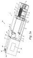
図面を参照すると、センサ−分与装置内にて使用し得るようにされた、図1のカートリッジ組立体10が図示されている。カートリッジ組立体10は、実質的に防湿型で且つ気密の装置である。図1のカートリッジ組立体10は、使い捨て型カートリッジ11と、端部キャップ12とを備えている。カートリッジ11は、外側カートリッジ13と、内側カートリッジ15とを備えている。内側カートリッジは、複数の試験センサ14と、機械的機構16とを備えている。端部キャップは、少なくとも1つの密封機構18を備えている。カートリッジ11は、複数の試験センサ14の各々が使用された後、使い捨て可能であるようにされている。複数の試験センサ14の各々が使用された後、カートリッジ11を端部キャップ12から分解し且つ、複数の未使用の試験センサを有する第二のカートリッジと交換することができる。
Referring to the drawings, there is illustrated the
図1を参照すると、外側カートリッジ13は、試験センサ14がカートリッジ11から出るときに通る開口部20を保持している。閉塞位置、すなわち密封位置において、開口部20は、少なくとも1つの密封機構18を使用して密封される。密封機構18は、内側カートリッジ15内にて複数の試験センサ14を保持するカートリッジ11の内部に空気及び湿気が入るのを防止し又は阻止する。開口部20は、外側カートリッジ13から内側カートリッジ15まで伸びている。開口部20は、複数の試験センサ14が同時に1つずつ貫通して動くのを許容し且つ、最終的に内側カートリッジ15及び外側カートリッジ13から出るのを許容する寸法とされている。特に、複数の試験センサ14は、同時に1つずつ、開口部20を介して内側カートリッジ15及び外側カートリッジ13から出る。
Referring to FIG. 1, the
端部キャップ12内に保持された密封機構18は、密封ドア19を備えており、該密封ドアは、該ドアが図1に示した密封位置にあるとき、開口部20にカバーをする。密封ドア19は、軸線に沿って回転し、ドア19が作動する間、開口部20に対して非整合状態となった場合、ドアが開口部20を密封するのを許容することができる。密封機構18は、開口部20を密封し且つ非密封状態とする間、密封ドア19が動くのを容易にする連結機構21を更に備えている。連結機構21は、図1に参照番号21a、21bとして示した少なくとも2つの固定点を備えている。固定点21a、21bは、密封ドア19が動く間、連結機構をその位置に維持する。
The
外側カートリッジ13の内面は、図1に参照番号22として示した1つ又はより多くの部材を備えている。部材22は、これらの部材がその外面と接触するとき、内側カートリッジ15の動きを停止させ且つ、内側カートリッジ15が開口部20に向けて更に動くのを阻止する。更に、部材22が内側カートリッジと接触するとき、内側カートリッジと外側カートリッジとの間に形成された空間を使用して乾燥剤材料26を収容することができる。
The inner surface of the
外側カートリッジ13は、内側カートリッジ15が動いているとき、複数のセンサ14の最上方センサを動かないように保持する保持機構又は作用部24を備えている。以下に更に説明するように、センサ−分与装置が作動する間、内側カートリッジ15は、開口部20の方向に向けて動く。この動きの間、保持機構24は、最上方試験センサと接触し且つ、センサ14の積層体の残りが内側カートリッジ15と共に動く間、試験センサをその位置に保持する。
The
外側カートリッジ13内での内側カートリッジ15の動きは、案内機構25によって案内される。案内機構25は、センサ−分与装置が作動する間、内側カートリッジ15が直線状の形態にて動くのを保証する。作用部25は、内側カートリッジ15を直線状に動かす三角形の輪郭外形を有する。
The movement of the
図1に示すように、複数の試験センサ14は内側カートリッジ15内に積層されている。複数の試験センサ14は、少なくとも1つの分析物質の試験を助け得るようにされている。上述したように、試験可能である分析物質の1つは、例えば、全血試料からのグルコースである。1つの実施の形態において、複数の試験センサ14は、試験すべき1つ又は複数の所望の分析物質と反応するよう適宜に選ばれた酵素を含むことになろう。グルコースと反応するよう使用することのできる1つの酵素は、ブドウ糖酸化酵素である。グルコース脱水素酵素のようなその他の酵素が使用可能であると考えられる。試験センサ14の一例は、ベイヤーコーポレーション(Bayer Corporation)に譲渡された米国特許明細書6,531,040号に開示されている。その他の試験センサをカートリッジ組立体10内にて使用可能であると考えられる。
As shown in FIG. 1, the plurality of
複数の試験センサ14は、異なるユーザの必要性に対応し得るよう、図1に示した数と異なる数とすることができる。典型的に、積層した試験センサは、約10ないし約100個のセンサを保持している。試験センサの貯蔵寿命及び使用寿命は限界があるため、頻繁でなく試験するユーザは、より頻繁に試験するユーザと比較して、試験センサの数が少ないカートリッジを望むであろう。
The number of
積層した試験センサ14を上方に押すためには、1つの実施の形態に従った機械的機構16を使用する。該機械的機構16は、内側カートリッジ15内に保持され、また、複数の試験センサの1つを開口部20を介してカートリッジ11から最終的に突き出すべく位置決めするのを助ける。機械的機構は、積層した試験センサ14に圧力を加えて複数の試験センサの1つを突き出し得るように配置することのできる任意の装置である。例えば、図1に示した機械的機構16は、2つのばねと、センサの積層体を上向きの態様にて案内するセンサ圧力板17とから成っている。積層した試験センサ14を上方に付勢するための機械的機構として色々な型式のばねを使用することができる。例えば、ばねは、圧縮ばね又はねじりばねとすることができる。ばねは、単純であり、また、使用し易い点にて望ましい。本発明の特定の実施の形態は、機構16の一部として単一のばねを有することができる一方、その他のもの(図1に例示したもののような)は、機構16の一部として2つのばねを備えることができる。
To push the stacked
試験センサ14内の試薬を保護するのを助けるため、望ましい包装材料及び(又は)乾燥剤材料を使用することができる。使い捨て型カートリッジ11は、典型的に、試験センサ14を保持する内側カートリッジ15の内部に空気が入るのを防止し又は阻止する材料にて包装されている。使い捨て型カートリッジ11を収納すべく使用できる1つの型式の除去可能な材料は、アルミニウム箔である。その他の型式の除去可能な包装物を使用することができると考えられる。乾燥剤材料を除去可能な包装物の内部に追加して、その内部にて適宜な湿度レベルを維持するのを助けることができると考えられる。試験センサ内の試薬が湿気に対する感受性がないならば、その場合、乾燥剤(存在するならば)を多く含むことは殆ど必要なく又は全く必要ない。乾燥剤材料を有するか又は有しない除去可能な包装物は、試験センサの貯蔵寿命を延ばすのを助ける。除去可能な包装物は、カートリッジ11を端部キャップ12に取り付ける前に、除去しなければならない。
Desired packaging materials and / or desiccant materials can be used to help protect the reagents in the
使い捨て型カートリッジ11は、最初に、瓶又はその他の型式の容器のような重合系容器内に配置することができる。容器は、空気又は湿気が容器の内部に入るのを防止し又は阻止する望ましいシールを有する使い捨て型カートリッジと同様の形状のものとすることができる。容器は、活性ヒンジを介して容器の他の部分に取り付けられる蓋を有することができる。乾燥剤を容器内に追加することが可能であることも考えられる。乾燥剤材料を有するか又は有しない容器は、試験センサの貯蔵寿命を引き延ばすのを助ける。使い捨て型カートリッジ11は、センサ−分与装置内に配置される前に容器から除去する。
The
乾燥剤材料26は、試験センサ14を保持する内側カートリッジ15の内部にて適宜な湿度レベルを維持するのを助けるべく使い捨て型カートリッジ11に追加されることが望ましい。本発明の特定の実施の形態において、乾燥剤材料26は、図1に例示するように、外側カートリッジ13と内側カートリッジ15との間の空間に追加することができる。具体的には、密封ドア19を開け且つ、センサを内側カートリッジ15から引き出す毎に、幾分かの湿気は外側カートリッジ13の内部に入る可能性があるが、かかる湿気は、乾燥剤材料26によって望ましいように吸収され、試験センサ内の試薬を劣化しないよう保護する。適正な湿度レベルを維持することにより、試験センサ内の試薬材料は保護される。乾燥剤材料26の量は、所望の貯蔵寿命(複数の試験センサの何れかが使用される前の期間)を得るのに十分でなければならない。より具体的には、貯蔵寿命とは、典型的に、カートリッジ11が包装材料(使用されるならば)から除去されるまでの期間を意味する。乾燥剤材料26の量は、また、所望の使用寿命(複数の試験センサの1つを最初に使用した後の期間)を得るのにも十分でなければならない。より具体的には、使用寿命とは、カートリッジ11が包装材料(使用されるならば)から除去された後の期間を意味する。
使い捨て型容器、使い捨て型容器を収納する除去可能な包装物又は使い捨て型カートリッジ11を保持する容器内に含めることのできる乾燥剤の例は、商業的に入手可能な乾燥剤を含む。乾燥剤は、ボール、錠剤、粒状物又は紙を含む幾つかの形状の形態とすることができる。例えば、乾燥剤は、分子ふるい球又は厚い乾燥剤紙とすることができる。乾燥剤材料の非限定的な例は、例えば、分子ふるいビードの形態にて、ニューヨーク州、バッファローのマルチソーブ(Multisorb)から購入することができる。本発明の特定の実施の形態において、外側カートリッジは、乾燥剤にて被覆するか又はこれと代替的に、乾燥剤材料にて出来たものとしてもよい。
Examples of desiccants that can be included in a disposable container, a removable package containing the disposable container, or a container holding the
乾燥剤は、湿度感受性のない試験センサに対して使用されることはないと考えられる。使用した乾燥剤(使用されるならば)の量は、試験センサの湿度感受性の程度及び所望の貯蔵寿命の期間に依存する。 The desiccant is not expected to be used for test sensors that are not moisture sensitive. The amount of desiccant used (if used) depends on the degree of humidity sensitivity of the test sensor and the desired shelf life period.
密封ドア19は、閉塞位置(図1に図示)から開放位置(図2aないし図2d、図3a及び図3bに図示)まで動き得るようにされている。閉塞位置において、密封ドア19は、カートリッジ11の内部を密封し、環境及びその環境内の全ての湿気が試験センサ14に接触するのを防止する。かかる閉塞位置において、密封ドア19は、実質的に防湿型で且つ実質的に気密のカートリッジを提供する。密封ドア19は、湿気が開口部20を介して入り且つ、複数のセンサの少なくとも貯蔵寿命及び使用寿命に亙って複数の試験センサ14に影響を与えるのを防止し又は阻止する望ましい設計とされている。密封ドア19が開放位置にあるとき、試験センサ14は、同時に1つずつ、開口部20を通って動かし、最終的に、開口部20を介して出るようにすることができる。
The sealing
端部キャップ12は、多岐に亙る材料で出来たものとすることができるが、典型的に、重合系材料にて出来ている。端部キャップ12を形成するときに使用可能である重合系材料の幾つかの例は、ポリカーボネート、ABS、ナイロン、ポリスチレン、ポリプロピレン又はそれらの組み合わせを含む。ハウジングを形成するとき、例えば、潤滑のためテフロン(TEFLON)(登録商標名)又は強度を増すためガラスのようなその他の添加物を追加することができる。その他の添加物を採用することが可能であると考えられる。ポリカーボネートは、耐久性のある材料であり、また、空気(特に、酸素及び湿気)が端部キャップ12に入り、また、密封ドア19を開放したとき、カートリッジ11に入る可能性があるのを防止し又は阻止する能力があることを含む、幾つかの理由のため望ましい。また、外側カートリッジが2つの別個の部分にて形成されるならば、ポリカーボネートは、それ自体に密封することができる。このことは、2つのカートリッジ部分が超音波溶接される方法にて望ましいであろう。
The
端部キャップ12は、射出成形方法を含む当該技術の当業者に既知の方法により形成することができる。射出成形方法が使用されるならば、肉厚は、典型的に、通常の範囲内にて設計される。成形方法のようなその他の方法が使用可能であると考えられる。
The
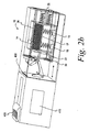
図2aを参照すると、1つの実施の形態に従ったセンサ−分与装置400が図示されている。センサ−分与装置は、分析物質の濃度を測定するため使用される。本発明を使用して測定可能である分析物質は、グルコース、脂質プロフィール(例えば、コレステロール、トリグリセリド、LDL、及びHDL)、微量アルブミン、ヘモグロビンA1C、フルクトース、乳酸塩又はビリルビンを含む。しかし、本発明は、これらの特定の分析物質に限定されず、その他の分析物質の濃度が測定可能であると考えられる。分析物質は、例えば、全血試料、血清試料、血漿試料、又はISF(間質液)及び尿のようなその他の体液とすることができる。
Referring to FIG. 2a, a sensor-dispensing
センサ−分与装置400は、カートリッジ組立体10と、摺動組立体402と、装置のハウジング404とを備えている。図2aに示すように、摺動組立体402は、スライダ406と、該スライダ406に取り付けられた把持機構408とを有する。図2bないし図2dに示すように、装置のハウジング404は、カートリッジ組立体10を受け入れ得るようにされている。カートリッジ組立体10は、簡単で且つ容易な態様にてセンサ−分与装置400の装置のハウジング404から除去し且つ該装置のハウジング内に装填されることが望ましい。装置のハウジングは、測定される特定の分析物質の量に比例した測定値を表示するLCDスクリーン410を備えることができる。図2aないし図2dに示した装置のハウジング404は、カートリッジ組立体10をハウジング404の端部に装填し、該ハウジングの端部から把持機構408はカートリッジ11に向けて伸びている。側部装填型装置に代えて、装置のハウジングは底部装填型装置としてもよい。
The sensor-dispensing
その他のカートリッジ及びカートリッジ組立体が使用可能であると考えられる。使用すべきカートリッジの形状に依存して、装置ハウジングの内部はカートリッジの形状に相応するよう設計変更することができる。 It is contemplated that other cartridges and cartridge assemblies can be used. Depending on the shape of the cartridge to be used, the interior of the device housing can be modified to accommodate the shape of the cartridge.
図2aを参照すると、スライダ406は第一の位置にて示されている。スライダ406を前方方向(図2cの矢印Aの方向)に向けて手操作にて動かすのを続けることにより、スライダ406は、第二の位置まで動かされる(図2a、2b参照)。図2dのスライダ406は、図2cのスライダ406よりもキャリッジ組立体10により近い位置に配置される。
Referring to FIG. 2a, the
摺動組立体402は、複数の試験センサ14の1つを内側カートリッジ15から把持し且つ、図3aに示すように、その試験センサを少なくとも部分的に密封機構18を通して引っ張り得るようにされている。スライダ406が第一の位置にあるとき(図2a、図2b)、把持機構408(これもまた、図2a、図2bのその第一の位置にある)は、複数の試験センサ14の何れとも接触せず、ハウジング404にてほぼ完全に保持される。スライダ406が前方方向に向けて動くと(図2cの矢印Aの方向参照)、把持機構408(図2c、図2d参照)も前方に向けて動かされる。
The sliding
図2aを再度参照すると、ハウジング404の外側は、ハウジング404の上方部分に外側通路412を形成する。スライダの動きを容易にするため、図2aのスライダ406は、外側通路412に沿って案内される(図2c参照)。スライダ406は、接続機構(図示せず)を介して把持機構と接続され、スライダ406の動きには、常に、把持機構408の動きが伴う。ユーザによる把持を容易にするため、スライダ406は、図2a、図2bに示したようなその頂部面にリッジ又は鋸歯状部分を形成することができる。
Referring again to FIG. 2 a, the outside of the
図2aを再度参照すると、把持機構408は、内側通路414内に配置され、この内側通路は、把持機構408を第一の位置(図2a、図2b)から第二の位置(図2c、図2d、図3a、図3b)まで、また、第一の位置に戻る動きを容易にし且つ、その動き及び位置決めを案内するのを助ける。摺動組立体402はまた、把持機構408が適正な平面内にて動くのを更に保証し得るよう案内ブロック416も有する。案内ブロック416は、スライダ406の下方に配置され、また、把持機構408と共に内側通路414に沿って動く。本発明の特定の実施の形態において、案内ブロック416は、スライダ406を把持機構408と接続するための接続機構である。
Referring again to FIG. 2a, the
1つの方法に従い、図2aの把持機構408はハウジングの開口部420を通って伸び、その後、連結機構21(図1)に向けて伸び且つ該連結機構21と接触する。連結機構21と接触したとき、把持機構408は、カートリッジの開口部20に向けて更に伸びる。連結機構21と接触し、また、把持機構408が前方への動きを続けることにより、密封ドア19は動いて開口部20(図2c)を非密封状態にする。把持機構408は、開口部20を通る動きを続け、その後、内側カートリッジ15と接触する。内側カートリッジと接触した後、把持機構は、該把持機構が複数の試験センサ14の1つと接触する迄、前方への動きを続ける(図2c、図2d参照)。
According to one method, the
図2aに示すように、一定の空隙35がストッパ部材30と開口部420との間に存在するようにすることができる。以下に更に説明するように、ストッパ部材は、把持機構が単一のセンサを把持し且つ、該センサを内側カートリッジ15内に配置されたセンサ14の積層体から引き出すとき、カートリッジ11の前方への動きを停止させる。一定の空隙35は、試験センサがカートリッジ11から出た後、該試験センサに対する空間を提供する。一定の空隙35の別の用途は、センサ−分与装置400内にランセットを配置するための位置を提供することである。
As shown in FIG. 2 a, a certain gap 35 can be present between the
開口部420は、把持機構408をシール18及び複数の試験センサ14の1つに対して適正に整合させる。スライダ406が前方方向に動くと、把持機構408は、シール18を通して複数の試験センサ14の1つと接触し且つ、該1つの試験センサを把持する。スライダ406が第二の位置(図2c、図2d参照)まで動くと、把持機構408は、保持機構24によってその位置に締め付けられた複数の試験センサ14の1つを把持するのを継続する。把持機構408が複数の試験センサ14の1つを把持した後、スライダ406は第一の位置まで動いて戻る。スライダ406が第一の位置まで動いて戻ると、把持機構408は、センサが複数の試験センサ14の積層体から分離され且つ、シール18を少なくとも部分的に通過する迄(図3a、図3b参照)、複数の試験センサ14の1つを把持し且つ、引っ張ることを続行する。把持機構408が複数の試験センサ14の1つを把持し且つ引っ張ると、センサの積層体を備える内側カートリッジ15は、ハウジング404に向けた動きを開始する(図2c参照)。ハウジング404に向けたカートリッジ11の動きは、ストッパ部材30によって停止され、カートリッジは該ストッパ部材にてその位置に掛止する。カートリッジ11の前方への動きがストッパ部材30によって停止されると、把持機構408は、単一のセンサをセンサ14の積層体から分離させる。スライダ406が第一の位置に復帰した後、把持機構408は、センサをその把り部内に保持し且つ、ユーザが使用するのに適した態様にてセンサを提供する(図4参照)。
The
試験センサ14を把持し且つ引っ張る間、内側カートリッジ15の動きは、外側カートリッジの内面における作用部22によって停止され、このことは、内側カートリッジの壁が外側カートリッジの内壁と接触するのを防止することになる(図1参照)。
While gripping and pulling the
本発明の特定の実施の形態において、把持機構408は、センサ14をハウジング404内に保持された計測電子機器(図示せず)と連結する電気接点を備えている。センサ14は、摺動接点を介し又は可撓性の回路ケーブル(図示せず)を介して計測電子機器に連結することができる。
In certain embodiments of the present invention, the
図4には、ハウジング404がカートリッジ組立体10から分離したセンサ分与装置400が示されている。図4に示すように、単一の試験センサ14が内側カートリッジ15内に配置された複数の試験センサから分離し且つ引き出された後、スライダ406は、第一の位置に復帰し、把持機構408は、センサをその把み部内に保持し且つ、ユーザが使用するのに適した態様にてセンサを提供する。
FIG. 4 shows a
本発明の特定の実施の形態において、センサは、カートリッジから引き出された後、側方向を向いた状態にて提供される。
センサの試験端部は、試験すべき流体試料(例えば、全血試料)と接触するよう配置し得るようにされている。全血試料は、ランセットのような突き刺し装置によって発生させることができる。全血試料は、センサ−分与装置から分離し又はセンサ−分与装置内に一体化することができるランセットにより取得することができる。突き刺し装置は、例えば、人間の指を刺すことにより血液を取得することができる。
In certain embodiments of the invention, the sensor is provided in a side-facing state after being pulled out of the cartridge.
The test end of the sensor is adapted to be placed in contact with a fluid sample to be tested (eg, a whole blood sample). The whole blood sample can be generated by a piercing device such as a lancet. The whole blood sample can be obtained by a lancet that can be separated from or integrated into the sensor-dispensing device. The piercing device can acquire blood by piercing a human finger, for example.
1つの方法に従い、全血試料は、(a)試験センサの1つを全血試料を受け入れる位置にて前進させるステップと、(b)全血試料を発生させるステップと、(c)試験センサ及び全血試料を接触させ、血液が全体として毛管作用によりセンサ内に吸引されるようにするステップとにより、試験のため準備することができる。 According to one method, a whole blood sample is obtained by: (a) advancing one of the test sensors at a position for receiving a whole blood sample; (b) generating a whole blood sample; (c) a test sensor; Contacting a whole blood sample and allowing blood to be drawn into the sensor as a whole by capillary action can be prepared for testing.
センサには、典型的に、センサの前端、すなわち試験端部からセンサ内に配設されたバイオセンシング又は試薬材料まで伸びる毛管通路が設けられている。センサの試験端部は、流体(例えば、人間の指を刺した後、その指に集まる血液)内に配置されたとき、流体の一部分は、毛管作用によって毛管通路内に吸引される。次に、流体は、センサ内の試薬材料と化学的に反応し、試験される血液中の血糖レベルを表示する電気信号が供給され、その後、電気組立体に伝送されるようにする。 The sensor is typically provided with a capillary passage that extends from the front end of the sensor, ie, the test end, to the biosensing or reagent material disposed within the sensor. When the test end of the sensor is placed in a fluid (eg, blood that collects on a finger after being stabbed by a human finger), a portion of the fluid is aspirated into the capillary passage by capillary action. The fluid then chemically reacts with the reagent material in the sensor so that an electrical signal is provided that is indicative of the blood glucose level in the blood being tested and then transmitted to the electrical assembly.
試験が完了した後、幾つかの方法によって試験センサをハウジング404から除去することができる。1つの実施の形態において、センサ−分与装置は、使用済みの試験センサをセンサ−分与装置から突き出す突き出し機構を備えることもできる。かかる実施の形態において、試験センサは、強制的に解放される。別の実施の形態において、試験センサは、試験センサの把み部を解放することにより突き出すことができ、その結果、試験センサは、重力によってセンサ−分与装置から廃棄される。更なる実施の形態において、試験センサは、センサ−分与装置から手操作にて除去することもできる。
After the test is complete, the test sensor can be removed from the
図3a、図3bに示すように、把持機構408は、第二の位置まで動かされたとき、カートリッジの開口部20を貫通して伸びることができる。この伸びた位置にあるとき、把持機構408は、試験センサ14の1つと接触し且つ、該1つの試験センサを把持する。
As shown in FIGS. 3a and 3b, the
スライダ406が後方向(すなわち、図2cに示した矢印Aの方向と反対の方向)に向けてその第二の位置から図2aの第一の位置まで動くと、把持機構408は、同時に、その第二の位置から第一の位置まで動き、その結果、把持機構408はシール18を貫通して進む。スライダ406及び把持機構408が第一の位置にある間、カートリッジ11は、実質的に防湿型で且つ気密である。センサ−分与装置は、ボタンを押すことに応答するよう、スライダ機構を自動的に作動させることが可能であると考えられる。
When the
ハウジング404及びスライダ406は、典型的に、重合系材料にて出来ている。重合系材料の非限定的な例は、ポリカーボネート、ABS、ナイロン、ポリプロピレン又はそれらの組み合わせを含む。スライダを形成する重合系材料に添加物を加えることができる。スライダは、金属材料のようなその他の材料にて出来たものとすることも可能であると考えられる。
The
把持機構408は、金属又は重合系材料にて出来たものとすることができる。一部の非限定的な金属材料は、ステンレス鋼及び適宜なめっきを施した青銅を含む。重合系材料の非限定的な例は、ポリカーボネート、ABS、ナイロン、ポリプロピレン又はそれらの組み合わせを含む。把持機構を形成する重合系材料に添加物を加えることができる。
The
センサ−分与装置400は、典型的に、血糖の試験手順の間、生成されたデータを処理し且つ(又は)記憶するマイクロプロセッサ又は同様のものを含む。このデータは、ハウジング404の表面に配置された液晶ディスプレイ410に表示することができる(図2a参照)。液晶ディスプレイは、センサ−分与装置400にて試験手順からの情報を表示する。
The sensor-dispensing
センサ−分与装置が使用されているとき、表示可能である情報の一部は、次のもの、すなわち電池の表示、数値表示、残るセンサの数の表示、センサ−分与装置内へのカートリッジの装填の表示、使用血液の表示、温度表示又はそれらの色々な組み合わせを含む。 When the sensor-dispensing device is in use, some of the information that can be displayed includes the following: battery display, numeric display, number of remaining sensors, cartridge in sensor-dispensing device Loading indication, blood usage indication, temperature indication or various combinations thereof.
センサ−分与装置400はまた、電池−トレー組立体の開口部を保持することもできる。電池−トレー組立体は、その内部に電池が配設される電池−トレーを有する。電池−トレー組立体は、センサ−分与装置400の一側部の開口部内に挿入する。このように挿入されたとき、電池は、回路板組立体における回路(図示せず)及び液晶ディスプレイ410を含む、装置400内の電子機器に対する電力を提供する。
The sensor-dispensing
本発明は、図示した実施の形態の詳細に関して説明したが、これらの詳細は、本発明の範囲を特許請求の範囲に規定されたように制限することを意図するものではない。例えば、血糖以外の流体を試験するため、センサ−分与装置400を使用することができる。実際上、センサ−分与装置400は、試薬材料を使用して分析することのできる任意の型式の化学的性質の流体の分析に関連して使用することができる。
Although the invention has been described with reference to details of the illustrated embodiments, these details are not intended to limit the scope of the invention as defined in the claims. For example, the sensor-dispensing
代替的な実施の形態A
流体の分析物質の濃度を測定し得るようにされたセンサ−分与装置であって、
端部キャップと、使い捨て型カートリッジと、密封機構とを有するカートリッジ組立体であって、使い捨て型カートリッジは、外側カートリッジと、内側カートリッジとを備え、内側カートリッジは、その内部に積層体にて配置された複数のセンサを保持し、外側カートリッジは、内側カートリッジが動く間、センサの少なくとも1つをその位置に保持する保持機構を有し、密封機構は、実質的に湿気不浸透性であるシールを形成し、内側カートリッジ内のセンサを雰囲気の湿気から保護し得るようにされた、上記カートリッジ組立体と、
センサを把持し且つセンサを外側カートリッジの開口部を通して積層体から分与した位置まで引っ張り得るようにされた把持機構とを備え、
外側カートリッジは、センサ及び把持機構が貫通して通るのを許容するのに十分な寸法の開口部を形成する、上記センサ−分与装置である。
代替的な実施の形態B
流体中の分析物質の濃度を測定する機構を更に備える、実施の形態Aのセンサ−分与装置である。
代替的な実施の形態C
把持機構は、第一の位置と第二の位置との間を往復状態にて摺動可能である、実施の形態Aのセンサ−分与装置である。
代替的な実施の形態D
把持機構が第一の位置から第二の位置まで動くことによって、把持機構はその少なくとも一部分を密封面と密封機構との間に挿入し、シールを破断し、次に、センサをセンサと接触する位置に押すのを許容するのに十分な程度、移動して、把持機構が第二の位置から第一の位置まで移動することにより、センサは開口部を通して引っ張られるようにした、実施の形態Cのセンサ−分与装置である。
代替的な実施の形態E
把持機構は、第一の位置から第二の位置まで移動するとき、密封機構と、積層体中の最上方センサとの双方と接触する、実施の形態Dのセンサ−分与装置である。
代替的な実施の形態F
把持機構は、ユーザが手操作によって第一の位置と、第二の位置との間にて押すことができるようにされた、実施の形態Eのセンサ−分与装置である。
代替的な実施の形態G
密封機構は、端部キャップに取り付けられる、実施の形態Aのセンサ−分与装置である。
代替的な実施の形態H
密封機構は、密封ドアと、連結機構とを有し、連結機構は密封ドアが動くのを容易にするのを助ける、実施の形態Gのセンサ−分与装置である。
代替的な実施の形態I
開口部の寸法は、同時に1つのセンサのみを貫通して引っ張ることを許容する、実施の形態Aのセンサ−分与装置である。
代替的な実施の形態J
外側ハウジングは、正確に1つの開口部を有する、実施の形態Aのセンサ−分与装置である。
代替的な実施の形態K
保持機構は、内側カートリッジが把持機構によって外側カートリッジに対して動かされる間、最上方センサをその位置に保持する、実施の形態Aのセンサ−分与装置である。
代替的な実施の形態L
把持機構は、センサをセンサ−分与装置の電子機器に連結する電気接点を保持する、実施の形態Aのセンサ−分与装置である。
代替的な実施の形態M
流体の分析物質の濃度を測定し得るようにされたセンサ−分与装置内にて使用し得るようにされたカートリッジ組立体であって、
端部キャップと、
外側カートリッジと、内側カートリッジとを備える使い捨て型カートリッジであって、内側カートリッジはその内部に積層体にて配置された複数のセンサを保持し、該複数のセンサの各々は、流体中の分析物質の濃度に応答して信号を発生させるのに十分な試薬を支持し、外側カートリッジは、センサが開口部を貫通して通るのを許容するのに十分な寸法の開口部を形成し、外側カートリッジは、内側カートリッジが動く間、センサの少なくとも1つをその位置に保持する保持機構を有する、上記使い捨て型カートリッジと、
実質的に湿気不浸透性であるシールを形成し、内側カートリッジ内のセンサを雰囲気の湿気から保護し得るようにされた密封機構とを備えるカートリッジ組立体である。
代替的な実施の形態N
密封機構が端部キャップに取り付けられた、実施の形態Mのカートリッジ組立体である。
代替的な実施の形態O
密封機構は、密封ドアと、連結機構とを有し、該連結機構は、密封ドアが動くのを容易にするのを助ける、実施の形態Nのカートリッジ組立体である。
代替的な実施の形態P
開口部の寸法は、同時に1つのセンサのみを貫通して引き出すのを許容する寸法である、実施の形態Mのカートリッジ組立体である。
代替的な実施の形態Q
外側カートリッジは厳密に1つの開口部を有する、実施の形態Mのカートリッジ組立体である。
代替的な実施の形態R
試験センサを同時に1つずつ内側カートリッジから除去し得るよう配置する機械的機構を更に有する、実施の形態Mのカートリッジ組立体である。
代替的な実施の形態S
保持機構は、内側カートリッジが外側カートリッジに対して動く間、最上方センサをその位置に保持する、実施の形態Mのカートリッジ組立体である。
代替的な方法T
複数のセンサを保持するセンサパックを取り扱い得るようにされたセンサ−分与装置を作動させる方法であって、
カートリッジ組立体と、把持機構とを有するセンサ−分与装置であって、カートリッジ組立体は、端部キャップと、使い捨て型カートリッジと、密封機構とを有し、使い捨て型カートリッジは、外側カートリッジと、内側カートリッジとを備え、内側カートリッジは、その内部に積層体にて配置された複数のセンサを保持し、外側カートリッジは、内側カートリッジが動く間、センサの少なくとも1つをその位置に保持する保持機構を有し、外側カートリッジは、センサ及び把持機構が貫通して通るのを許容するのに十分な寸法の開口部を形成し、密封機構は、内側カートリッジ内のセンサを雰囲気の湿気から保護し得るよう実質的に湿気不浸透性であるシールを形成し得るようにされた、上記センサ−分与装置を提供するステップと、
密封機構を開放位置まで動かし且つ、複数の試験センサの1つと接触するよう把持機構を前進させるステップと、
試験センサを把持機構を介してカートリッジ組立体の開口部を通して引っ張るステップと、
分析物質を有する流体を試験センサの上に配置するステップと、
分析物質の濃度を測定するステップとを備える、センサ−分与装置を作動させる方法である。
代替的な方法U
分析物質はグルコースである方法Tの方法である。
代替的な方法V
把持機構を前進させるステップは、把持機構を第一の位置と第二の位置との間にて往復状態に摺動させるステップを含む、方法Tの方法である。
代替的な方法W
密封機構は端部キャップに取り付けられる、方法Tの方法である。
代替的な方法X
密封機構は、密封ドアと、連結機構とを有し、連結機構は、密封ドアの動きを容易にするのを助ける、方法Tの方法である。
代替的な方法Y
開口部の寸法は、同時に1つのセンサのみを貫通して引っ張るのを許容する、方法Tの方法である。
代替的な方法Z
外側ハウジングは厳密に1つの開口部を有する、方法Tの方法である。
代替的な方法AA
保持機構は、内側カートリッジが把持機構によって外側カートリッジに対して動く間、最上方センサをその位置に配置する、方法Tの方法である。
代替的な方法BB
把持機構は、センサをセンサ−分与装置の電子機器に連結する電気接点を保持する、方法Tの方法である。
Alternative embodiment A
A sensor-dispensing device adapted to measure the concentration of an analyte in a fluid comprising:
A cartridge assembly having an end cap, a disposable cartridge, and a sealing mechanism, wherein the disposable cartridge includes an outer cartridge and an inner cartridge, and the inner cartridge is disposed in a laminated body therein. A plurality of sensors, the outer cartridge having a holding mechanism that holds at least one of the sensors in position during movement of the inner cartridge, and the sealing mechanism includes a seal that is substantially moisture impermeable. The cartridge assembly formed and adapted to protect the sensor in the inner cartridge from atmospheric moisture;
A gripping mechanism adapted to grip the sensor and to pull the sensor through the opening of the outer cartridge to a dispensed position from the stack;
The outer cartridge is the sensor-dispensing device described above that forms an opening of sufficient size to allow the sensor and gripping mechanism to pass therethrough.
Alternative embodiment B
The sensor-dispensing device of embodiment A further comprising a mechanism for measuring the concentration of the analyte in the fluid.
Alternative embodiment C
The gripping mechanism is the sensor-dispensing device according to embodiment A, which is slidable in a reciprocating manner between a first position and a second position.
Alternative embodiment D
As the gripping mechanism moves from the first position to the second position, the gripping mechanism inserts at least a portion thereof between the sealing surface and the sealing mechanism, breaks the seal, and then contacts the sensor with the sensor Embodiment C wherein the sensor is pulled through the opening by moving enough to allow pushing into position and the gripping mechanism moving from the second position to the first position. The sensor-dispensing device.
Alternative embodiment E
The gripping mechanism is the sensor-dispensing device of embodiment D that contacts both the sealing mechanism and the uppermost sensor in the stack as it moves from the first position to the second position.
Alternative embodiment F
The gripping mechanism is the sensor-dispensing device according to embodiment E, in which the user can manually press between the first position and the second position.
Alternative embodiment G
The sealing mechanism is the sensor-dispensing device of embodiment A attached to the end cap.
Alternative embodiment H
The sealing mechanism is the sensor-dispensing device of embodiment G having a sealing door and a coupling mechanism, the coupling mechanism helping to facilitate the movement of the sealing door.
Alternative embodiment I
The size of the opening is the sensor-dispensing device of embodiment A that allows pulling through only one sensor at a time.
Alternative embodiment J
The outer housing is the sensor-dispensing device of embodiment A having exactly one opening.
Alternative embodiment K
The holding mechanism is the sensor-dispensing device of embodiment A that holds the uppermost sensor in place while the inner cartridge is moved relative to the outer cartridge by the gripping mechanism.
Alternative embodiment L
The gripping mechanism is the sensor-dispensing device of embodiment A that holds electrical contacts that couple the sensor to the sensor-dispensing device electronics.
Alternative embodiment M
A cartridge assembly adapted for use in a sensor-dispensing device adapted to measure the concentration of an analyte in a fluid comprising:
An end cap;
A disposable cartridge comprising an outer cartridge and an inner cartridge, the inner cartridge holding a plurality of sensors disposed in a laminate therein, each of the plurality of sensors comprising an analyte in a fluid Sufficient reagent is supported to generate a signal in response to the concentration, and the outer cartridge forms an opening of sufficient dimensions to allow the sensor to pass through the opening, and the outer cartridge The disposable cartridge having a retention mechanism that holds at least one of the sensors in position while the inner cartridge moves;
And a sealing mechanism configured to form a substantially moisture impervious seal and to protect the sensor in the inner cartridge from ambient moisture.
Alternative embodiment N
The cartridge assembly of embodiment M, wherein the sealing mechanism is attached to the end cap.
Alternative embodiment O
The sealing mechanism is a cartridge assembly of embodiment N that includes a sealing door and a coupling mechanism, the coupling mechanism assisting in facilitating movement of the sealing door.
Alternative embodiment P
The dimensions of the opening are the cartridge assembly of embodiment M that is dimensioned to allow only one sensor to be pulled through and drawn out at the same time.
Alternative embodiment Q
The outer cartridge is the cartridge assembly of embodiment M having exactly one opening.
Alternative embodiment R
The cartridge assembly of embodiment M, further comprising a mechanical mechanism that positions the test sensors so that they can be removed from the inner cartridge one at a time.
Alternative embodiment S
The holding mechanism is the cartridge assembly of embodiment M that holds the uppermost sensor in place while the inner cartridge moves relative to the outer cartridge.
Alternative method T
A method of operating a sensor-dispensing device adapted to handle a sensor pack holding a plurality of sensors, comprising:
A sensor-dispensing device having a cartridge assembly and a gripping mechanism, the cartridge assembly having an end cap, a disposable cartridge, and a sealing mechanism, wherein the disposable cartridge is an outer cartridge; An inner cartridge, the inner cartridge holding a plurality of sensors disposed in a stack therein, and the outer cartridge holding a mechanism for holding at least one of the sensors in position while the inner cartridge moves And the outer cartridge forms an opening sized sufficiently to allow the sensor and gripping mechanism to pass therethrough, and the sealing mechanism may protect the sensor in the inner cartridge from ambient moisture. Providing said sensor-dispensing device adapted to form a substantially moisture-impermeable seal;
Moving the sealing mechanism to an open position and advancing the gripping mechanism to contact one of the plurality of test sensors;
Pulling the test sensor through the opening of the cartridge assembly via a gripping mechanism;
Placing a fluid having an analyte over a test sensor;
Measuring the concentration of the analyte, the method of operating a sensor-dispensing device.
Alternative method U
The method of method T, wherein the analyte is glucose.
Alternative method V
The step of advancing the gripping mechanism is the method of method T including the step of sliding the gripping mechanism back and forth between the first position and the second position.
Alternative method W
The sealing mechanism is a method T method that is attached to the end cap.
Alternative method X
The sealing mechanism is a method T method that includes a sealing door and a coupling mechanism, the coupling mechanism helping facilitate movement of the sealing door.
Alternative method Y
The size of the opening is the method of method T that allows it to be pulled through only one sensor at a time.
Alternative method Z
The method of method T, wherein the outer housing has exactly one opening.
Alternative method AA
The holding mechanism is a method of method T in which the uppermost sensor is placed in that position while the inner cartridge is moved relative to the outer cartridge by the gripping mechanism.
Alternative method BB
The gripping mechanism is a method of method T that retains electrical contacts that couple the sensor to the electronics of the sensor-dispensing device.
本発明は、1つ又はより多くの特定的な実施の形態に関して説明したが、当該技術の当業者は、本発明の精神及び範囲から逸脱せずに、多数の変更を加えることが可能であることが認識されよう。これらの実施の形態及びその明らかな変形例の各々は、特許請求の範囲に記載された本発明の精神及び範囲に属するものと考えられる。 Although the invention has been described with respect to one or more specific embodiments, those skilled in the art can make numerous changes without departing from the spirit and scope of the invention. It will be recognized. Each of these embodiments and obvious variations thereof is considered to be within the spirit and scope of the present invention as set forth in the appended claims.
Claims (28)
端部キャップと、使い捨て型カートリッジと、密封機構とを有するカートリッジ組立体であって、使い捨て型カートリッジは、外側カートリッジと、内側カートリッジとを備え、内側カートリッジは、その内部に積層体にて配置された複数のセンサを保持し、外側カートリッジは、内側カートリッジが動く間、センサの少なくとも1つをその位置に保持する保持機構を有し、密封機構は、実質的に湿気不浸透性であるシールを形成し、内側カートリッジ内のセンサを雰囲気の湿気から保護し得るようにされた、前記カートリッジ組立体と、
センサを把持し且つ、センサを外側カートリッジの開口部を通して積層体から分与した位置まで引っ張り得るようにされた把持機構とを備え、
外側カートリッジは、センサ及び把持機構が貫通して通るのを許容するのに十分な寸法の開口部を形成する、センサ−分与装置。 In a sensor-dispensing device adapted to measure the concentration of an analyte in a fluid,
A cartridge assembly having an end cap, a disposable cartridge, and a sealing mechanism, wherein the disposable cartridge includes an outer cartridge and an inner cartridge, and the inner cartridge is disposed in a laminated body therein. A plurality of sensors, the outer cartridge having a holding mechanism that holds at least one of the sensors in position during movement of the inner cartridge, and the sealing mechanism includes a seal that is substantially moisture impermeable. Said cartridge assembly formed and adapted to protect a sensor in the inner cartridge from atmospheric moisture;
A gripping mechanism adapted to grip the sensor and to pull the sensor through the opening of the outer cartridge to a position dispensed from the stack;
The sensor-dispensing device, wherein the outer cartridge forms an opening sized sufficiently to allow the sensor and gripping mechanism to pass therethrough.
端部キャップと、
外側カートリッジと、内側カートリッジとを備える使い捨て型カートリッジであって、内側カートリッジは、その内部に積層体にて配置された複数のセンサを保持し、該複数のセンサの各々は、流体中の分析物質の濃度に応答して信号を発生させるのに十分な試薬を支持し、外側カートリッジは、センサが開口部を貫通して通るのを許容するのに十分な寸法の開口部を形成し、外側カートリッジは、内側カートリッジが動く間、センサの少なくとも1つをその位置に保持する保持機構を有する、前記使い捨て型カートリッジと、
実質的に湿気不浸透性であるシールを形成して内側カートリッジ内のセンサを雰囲気の湿気から保護し得るようにされた密封機構とを備える、カートリッジ組立体。 In a cartridge assembly adapted for use in a sensor-dispensing device adapted to measure the concentration of an analyte in a fluid,
An end cap;
A disposable cartridge comprising an outer cartridge and an inner cartridge, the inner cartridge holding a plurality of sensors arranged in a laminate therein, each of the plurality of sensors being an analyte in a fluid The outer cartridge forms an opening of sufficient size to support a sufficient amount of reagent to generate a signal in response to a concentration of the outer cartridge and to allow the sensor to pass through the opening; Said disposable cartridge having a retention mechanism that holds at least one of the sensors in position while the inner cartridge moves;
And a sealing mechanism adapted to form a substantially moisture impervious seal to protect the sensor in the inner cartridge from ambient moisture.
カートリッジ組立体と、把持機構とを有するセンサ−分与装置であって、カートリッジ組立体は、端部キャップと、使い捨て型カートリッジと、密封機構とを有し、使い捨て型カートリッジは、外側カートリッジと、内側カートリッジとを備え、内側カートリッジは、その内部に積層体にて配置された複数のセンサを保持し、外側カートリッジは、内側カートリッジが動く間、センサの少なくとも1つをその位置に保持する保持機構を有し、外側カートリッジは、センサ及び把持機構が貫通して通るのを許容するのに十分な寸法の開口部を形成し、密封機構は、内側カートリッジ内のセンサを雰囲気の湿気から保護し得るよう実質的に湿気不浸透性のシールを形成し得るようにされた、前記センサ−分与装置を提供するステップと、
密封機構を開放位置まで動かし且つ、複数の試験センサの1つと接触するよう把持機構を前進させるステップと、
試験センサを把持機構を介してカートリッジ組立体の開口部を通して引っ張るステップと、
分析物質を有する流体を試験センサの上に配置するステップと、
分析物質の濃度を測定するステップとを備える、センサ−分与装置を作動させる、方法。 A method of operating a sensor-dispensing device adapted to handle a sensor pack holding a plurality of sensors, comprising:
A sensor-dispensing device having a cartridge assembly and a gripping mechanism, the cartridge assembly having an end cap, a disposable cartridge, and a sealing mechanism, wherein the disposable cartridge is an outer cartridge; An inner cartridge, the inner cartridge holding a plurality of sensors disposed in a stack therein, and the outer cartridge holding a mechanism for holding at least one of the sensors in position while the inner cartridge moves And the outer cartridge forms an opening sized sufficiently to allow the sensor and gripping mechanism to pass therethrough, and the sealing mechanism may protect the sensor in the inner cartridge from ambient moisture. Providing said sensor-dispensing device adapted to form a substantially moisture impermeable seal;
Moving the sealing mechanism to an open position and advancing the gripping mechanism to contact one of the plurality of test sensors;
Pulling the test sensor through the opening of the cartridge assembly via a gripping mechanism;
Placing a fluid having an analyte over a test sensor;
Activating a sensor-dispensing device comprising the step of measuring the concentration of the analyte.
Applications Claiming Priority (2)
| Application Number | Priority Date | Filing Date | Title |
|---|---|---|---|
| US62083404P | 2004-10-21 | 2004-10-21 | |
| PCT/US2005/037364 WO2006047135A1 (en) | 2004-10-21 | 2005-10-19 | Sensor-dispensing device and mechanism for extracting sensor |
Publications (2)
| Publication Number | Publication Date |
|---|---|
| JP2008518204A true JP2008518204A (en) | 2008-05-29 |
| JP2008518204A5 JP2008518204A5 (en) | 2008-12-04 |
Family
ID=35613877
Family Applications (1)
| Application Number | Title | Priority Date | Filing Date |
|---|---|---|---|
| JP2007537960A Withdrawn JP2008518204A (en) | 2004-10-21 | 2005-10-19 | Sensor-dispensing device and mechanism for pulling out the sensor |
Country Status (11)
| Country | Link |
|---|---|
| US (1) | US8142733B2 (en) |
| EP (1) | EP1851539B1 (en) |
| JP (1) | JP2008518204A (en) |
| CN (1) | CN101061384A (en) |
| BR (1) | BRPI0516235A (en) |
| CA (1) | CA2584606A1 (en) |
| MX (1) | MX2007004756A (en) |
| NO (1) | NO20072572L (en) |
| RU (1) | RU2390023C2 (en) |
| TW (1) | TW200630610A (en) |
| WO (1) | WO2006047135A1 (en) |
Cited By (4)
| Publication number | Priority date | Publication date | Assignee | Title |
|---|---|---|---|---|
| WO2013187031A1 (en) * | 2012-06-11 | 2013-12-19 | パナソニック株式会社 | Sensor housing container and sensor attachment method using same |
| JP2014517910A (en) * | 2011-04-08 | 2014-07-24 | シーエスピー テクノロジーズ,インコーポレイティド | Strip dispenser and strip used therewith |
| JP2015232554A (en) * | 2014-05-13 | 2015-12-24 | アークレイ株式会社 | Measuring apparatus |
| US10234414B2 (en) | 2014-05-13 | 2019-03-19 | Arkray, Inc. | Measurement apparatus, and method for operating measurement apparatus |
Families Citing this family (80)
| Publication number | Priority date | Publication date | Assignee | Title |
|---|---|---|---|---|
| US6391005B1 (en) * | 1998-03-30 | 2002-05-21 | Agilent Technologies, Inc. | Apparatus and method for penetration with shaft having a sensor for sensing penetration depth |
| US8641644B2 (en) | 2000-11-21 | 2014-02-04 | Sanofi-Aventis Deutschland Gmbh | Blood testing apparatus having a rotatable cartridge with multiple lancing elements and testing means |
| US9795747B2 (en) | 2010-06-02 | 2017-10-24 | Sanofi-Aventis Deutschland Gmbh | Methods and apparatus for lancet actuation |
| US7041068B2 (en) | 2001-06-12 | 2006-05-09 | Pelikan Technologies, Inc. | Sampling module device and method |
| US9226699B2 (en) | 2002-04-19 | 2016-01-05 | Sanofi-Aventis Deutschland Gmbh | Body fluid sampling module with a continuous compression tissue interface surface |
| WO2002100460A2 (en) | 2001-06-12 | 2002-12-19 | Pelikan Technologies, Inc. | Electric lancet actuator |
| US9427532B2 (en) | 2001-06-12 | 2016-08-30 | Sanofi-Aventis Deutschland Gmbh | Tissue penetration device |
| US7981056B2 (en) | 2002-04-19 | 2011-07-19 | Pelikan Technologies, Inc. | Methods and apparatus for lancet actuation |
| US7749174B2 (en) | 2001-06-12 | 2010-07-06 | Pelikan Technologies, Inc. | Method and apparatus for lancet launching device intergrated onto a blood-sampling cartridge |
| US8337419B2 (en) * | 2002-04-19 | 2012-12-25 | Sanofi-Aventis Deutschland Gmbh | Tissue penetration device |
| JP4209767B2 (en) | 2001-06-12 | 2009-01-14 | ペリカン テクノロジーズ インコーポレイテッド | Self-optimized cutting instrument with adaptive means for temporary changes in skin properties |
| US9248267B2 (en) | 2002-04-19 | 2016-02-02 | Sanofi-Aventis Deustchland Gmbh | Tissue penetration device |
| US7491178B2 (en) | 2002-04-19 | 2009-02-17 | Pelikan Technologies, Inc. | Method and apparatus for penetrating tissue |
| US8221334B2 (en) | 2002-04-19 | 2012-07-17 | Sanofi-Aventis Deutschland Gmbh | Method and apparatus for penetrating tissue |
| US7229458B2 (en) | 2002-04-19 | 2007-06-12 | Pelikan Technologies, Inc. | Method and apparatus for penetrating tissue |
| US7892183B2 (en) | 2002-04-19 | 2011-02-22 | Pelikan Technologies, Inc. | Method and apparatus for body fluid sampling and analyte sensing |
| US7909778B2 (en) | 2002-04-19 | 2011-03-22 | Pelikan Technologies, Inc. | Method and apparatus for penetrating tissue |
| US7901362B2 (en) * | 2002-04-19 | 2011-03-08 | Pelikan Technologies, Inc. | Method and apparatus for penetrating tissue |
| US7331931B2 (en) | 2002-04-19 | 2008-02-19 | Pelikan Technologies, Inc. | Method and apparatus for penetrating tissue |
| US8784335B2 (en) | 2002-04-19 | 2014-07-22 | Sanofi-Aventis Deutschland Gmbh | Body fluid sampling device with a capacitive sensor |
| US8702624B2 (en) | 2006-09-29 | 2014-04-22 | Sanofi-Aventis Deutschland Gmbh | Analyte measurement device with a single shot actuator |
| US7547287B2 (en) * | 2002-04-19 | 2009-06-16 | Pelikan Technologies, Inc. | Method and apparatus for penetrating tissue |
| US8579831B2 (en) | 2002-04-19 | 2013-11-12 | Sanofi-Aventis Deutschland Gmbh | Method and apparatus for penetrating tissue |
| US8360992B2 (en) | 2002-04-19 | 2013-01-29 | Sanofi-Aventis Deutschland Gmbh | Method and apparatus for penetrating tissue |
| US7232451B2 (en) | 2002-04-19 | 2007-06-19 | Pelikan Technologies, Inc. | Method and apparatus for penetrating tissue |
| US8372016B2 (en) * | 2002-04-19 | 2013-02-12 | Sanofi-Aventis Deutschland Gmbh | Method and apparatus for body fluid sampling and analyte sensing |
| US8267870B2 (en) | 2002-04-19 | 2012-09-18 | Sanofi-Aventis Deutschland Gmbh | Method and apparatus for body fluid sampling with hybrid actuation |
| US7674232B2 (en) | 2002-04-19 | 2010-03-09 | Pelikan Technologies, Inc. | Method and apparatus for penetrating tissue |
| US7708701B2 (en) | 2002-04-19 | 2010-05-04 | Pelikan Technologies, Inc. | Method and apparatus for a multi-use body fluid sampling device |
| US7175642B2 (en) | 2002-04-19 | 2007-02-13 | Pelikan Technologies, Inc. | Methods and apparatus for lancet actuation |
| US9795334B2 (en) | 2002-04-19 | 2017-10-24 | Sanofi-Aventis Deutschland Gmbh | Method and apparatus for penetrating tissue |
| US7976476B2 (en) | 2002-04-19 | 2011-07-12 | Pelikan Technologies, Inc. | Device and method for variable speed lancet |
| US9314194B2 (en) * | 2002-04-19 | 2016-04-19 | Sanofi-Aventis Deutschland Gmbh | Tissue penetration device |
| US7648468B2 (en) * | 2002-04-19 | 2010-01-19 | Pelikon Technologies, Inc. | Method and apparatus for penetrating tissue |
| US7297122B2 (en) * | 2002-04-19 | 2007-11-20 | Pelikan Technologies, Inc. | Method and apparatus for penetrating tissue |
| US8574895B2 (en) | 2002-12-30 | 2013-11-05 | Sanofi-Aventis Deutschland Gmbh | Method and apparatus using optical techniques to measure analyte levels |
| US20070032812A1 (en) * | 2003-05-02 | 2007-02-08 | Pelikan Technologies, Inc. | Method and apparatus for a tissue penetrating device user interface |
| WO2004107975A2 (en) | 2003-05-30 | 2004-12-16 | Pelikan Technologies, Inc. | Method and apparatus for fluid injection |
| WO2004107964A2 (en) | 2003-06-06 | 2004-12-16 | Pelikan Technologies, Inc. | Blood harvesting device with electronic control |
| WO2006001797A1 (en) | 2004-06-14 | 2006-01-05 | Pelikan Technologies, Inc. | Low pain penetrating |
| US8282576B2 (en) | 2003-09-29 | 2012-10-09 | Sanofi-Aventis Deutschland Gmbh | Method and apparatus for an improved sample capture device |
| US9351680B2 (en) | 2003-10-14 | 2016-05-31 | Sanofi-Aventis Deutschland Gmbh | Method and apparatus for a variable user interface |
| US7822454B1 (en) | 2005-01-03 | 2010-10-26 | Pelikan Technologies, Inc. | Fluid sampling device with improved analyte detecting member configuration |
| EP1706026B1 (en) | 2003-12-31 | 2017-03-01 | Sanofi-Aventis Deutschland GmbH | Method and apparatus for improving fluidic flow and sample capture |
| US8828203B2 (en) | 2004-05-20 | 2014-09-09 | Sanofi-Aventis Deutschland Gmbh | Printable hydrogels for biosensors |
| EP1765194A4 (en) | 2004-06-03 | 2010-09-29 | Pelikan Technologies Inc | Method and apparatus for a fluid sampling device |
| US9775553B2 (en) | 2004-06-03 | 2017-10-03 | Sanofi-Aventis Deutschland Gmbh | Method and apparatus for a fluid sampling device |
| CA2584606A1 (en) | 2004-10-21 | 2006-05-04 | Bayer Healthcare Llc | Sensor-dispensing device and mechanism for extracting sensor |
| US20060167382A1 (en) * | 2004-12-30 | 2006-07-27 | Ajay Deshmukh | Method and apparatus for storing an analyte sampling and measurement device |
| US8652831B2 (en) * | 2004-12-30 | 2014-02-18 | Sanofi-Aventis Deutschland Gmbh | Method and apparatus for analyte measurement test time |
| US20090054811A1 (en) * | 2004-12-30 | 2009-02-26 | Dirk Boecker | Method and apparatus for analyte measurement test time |
| MX2007008566A (en) | 2005-01-14 | 2007-09-07 | Bayer Healthcare Llc | Test sensor cartridges and sensor-dispensing instruments. |
| US8016154B2 (en) * | 2005-05-25 | 2011-09-13 | Lifescan, Inc. | Sensor dispenser device and method of use |
| EP1919363B1 (en) * | 2005-07-14 | 2010-10-20 | Bayer HealthCare, LLC | Lancing device for one skin puncture |
| US8865743B2 (en) | 2006-01-06 | 2014-10-21 | Acelrx Pharmaceuticals, Inc. | Small volume oral transmucosal dosage forms containing sufentanil for treatment of pain |
| US9289583B2 (en) * | 2006-01-06 | 2016-03-22 | Acelrx Pharmaceuticals, Inc. | Methods for administering small volume oral transmucosal dosage forms using a dispensing device |
| US8252329B2 (en) | 2007-01-05 | 2012-08-28 | Acelrx Pharmaceuticals, Inc. | Bioadhesive drug formulations for oral transmucosal delivery |
| US8202535B2 (en) | 2006-01-06 | 2012-06-19 | Acelrx Pharmaceuticals, Inc. | Small-volume oral transmucosal dosage forms |
| US9066847B2 (en) | 2007-01-05 | 2015-06-30 | Aceirx Pharmaceuticals, Inc. | Storage and dispensing devices for administration of oral transmucosal dosage forms |
| US8357114B2 (en) | 2006-01-06 | 2013-01-22 | Acelrx Pharmaceuticals, Inc. | Drug dispensing device with flexible push rod |
| US8753308B2 (en) | 2006-01-06 | 2014-06-17 | Acelrx Pharmaceuticals, Inc. | Methods for administering small volume oral transmucosal dosage forms using a dispensing device |
| ATE513210T1 (en) | 2006-07-18 | 2011-07-15 | Roche Diagnostics Gmbh | SPACE-OPTIMIZED PORTABLE MEASURING SYSTEM |
| US20080217353A1 (en) * | 2007-03-06 | 2008-09-11 | Michael John Newman | Method of Dispensing A Test Strip |
| US9052305B2 (en) | 2007-03-06 | 2015-06-09 | Lifescan, Inc. | Test strip dispenser |
| WO2008111933A1 (en) * | 2007-03-12 | 2008-09-18 | Bayer Healthcare Llc | Single-sensor meter system with no sensor handling and method of using the same |
| ATE420353T1 (en) * | 2007-03-27 | 2009-01-15 | Hoffmann La Roche | ANALYZER WITH INTERCHANGEABLE TEST ELEMENT MAGAZINE |
| US20090209883A1 (en) * | 2008-01-17 | 2009-08-20 | Michael Higgins | Tissue penetrating apparatus |
| US9386944B2 (en) * | 2008-04-11 | 2016-07-12 | Sanofi-Aventis Deutschland Gmbh | Method and apparatus for analyte detecting device |
| US9375169B2 (en) | 2009-01-30 | 2016-06-28 | Sanofi-Aventis Deutschland Gmbh | Cam drive for managing disposable penetrating member actions with a single motor and motor and control system |
| WO2010107761A1 (en) * | 2009-03-18 | 2010-09-23 | Acelrx Pharmaceuticals, Inc. | Improved storage and dispensing devices for administration of oral transmucosal dosage forms |
| US20110182785A1 (en) * | 2010-01-22 | 2011-07-28 | Roche Diagnostics Operations, Inc. | Flat Pop-Up Primary Container And Methods of Manufacturing And Utilization Thereof |
| US8965476B2 (en) | 2010-04-16 | 2015-02-24 | Sanofi-Aventis Deutschland Gmbh | Tissue penetration device |
| EP2618144A1 (en) * | 2012-01-18 | 2013-07-24 | Medical Device UG | Method and container for loading a measuring device with measuring units |
| US9213043B2 (en) | 2012-05-15 | 2015-12-15 | Wellstat Diagnostics, Llc | Clinical diagnostic system including instrument and cartridge |
| US9625465B2 (en) | 2012-05-15 | 2017-04-18 | Defined Diagnostics, Llc | Clinical diagnostic systems |
| US9081001B2 (en) | 2012-05-15 | 2015-07-14 | Wellstat Diagnostics, Llc | Diagnostic systems and instruments |
| AU2015369710B2 (en) | 2014-12-23 | 2020-09-17 | Vertical Pharmaceuticals, Llc | Systems, devices and methods for dispensing oral transmucosal dosage forms |
| DK3368097T3 (en) | 2015-10-30 | 2020-04-20 | Acelrx Pharmaceuticals Inc | DEVICE AND METHODS FOR DELIVERING ORAL TRANSMUCOSAL DOSAGE FORMS |
| CN109998597B (en) * | 2018-01-05 | 2020-03-27 | 广州莲印医疗科技有限公司 | Fetal monitoring sensor management device |
| CN112758529B (en) * | 2020-12-24 | 2022-11-25 | 广州广电计量检测无锡有限公司 | Sample storage device |
Family Cites Families (64)
| Publication number | Priority date | Publication date | Assignee | Title |
|---|---|---|---|---|
| US3797488A (en) * | 1972-07-10 | 1974-03-19 | Ampoules Inc | Ampoule applicator with one-way clutch |
| FR2508305B1 (en) * | 1981-06-25 | 1986-04-11 | Slama Gerard | DEVICE FOR CAUSING A LITTLE BITE TO COLLECT A BLOOD DROP |
| US4449529A (en) * | 1981-11-18 | 1984-05-22 | Becton Dickinson And Company | Automatic retractable lancet assembly |
| US4517978A (en) * | 1983-01-13 | 1985-05-21 | Levin Paul D | Blood sampling instrument |
| US5279294A (en) * | 1985-04-08 | 1994-01-18 | Cascade Medical, Inc. | Medical diagnostic system |
| US4787398A (en) * | 1985-04-08 | 1988-11-29 | Garid, Inc. | Glucose medical monitoring system |
| US4627445A (en) * | 1985-04-08 | 1986-12-09 | Garid, Inc. | Glucose medical monitoring system |
| US4735203A (en) * | 1986-12-12 | 1988-04-05 | Ryder International Corporation | Retractable lancet |
| US4911344A (en) * | 1988-03-23 | 1990-03-27 | Tek-Aids Inc. | Strip dispenser box |
| US4990154A (en) * | 1989-06-19 | 1991-02-05 | Miles Inc. | Lancet assembly |
| US5196025A (en) * | 1990-05-21 | 1993-03-23 | Ryder International Corporation | Lancet actuator with retractable mechanism |
| US5231993A (en) * | 1991-11-20 | 1993-08-03 | Habley Medical Technology Corporation | Blood sampler and component tester with guide member |
| JP2572823Y2 (en) * | 1992-02-13 | 1998-05-25 | 株式会社アドバンス | Simple blood sampler |
| US5244116A (en) * | 1992-04-06 | 1993-09-14 | Leo Daniel W | Cosmetic sample dispenser with replaceable magazines |
| US5318583A (en) * | 1992-05-05 | 1994-06-07 | Ryder International Corporation | Lancet actuator mechanism |
| US5267963A (en) * | 1992-08-21 | 1993-12-07 | Nicholas Bachynsky | Medication injection device |
| US5304193A (en) * | 1993-08-12 | 1994-04-19 | Sam Zhadanov | Blood lancing device |
| CA2135706C (en) * | 1993-11-15 | 1999-06-15 | Walter E. Cover | Retractable-needle cannula insertion set with refinements to better control leakage, retraction speed, and reuse |
| US5350392A (en) * | 1994-02-03 | 1994-09-27 | Miles Inc. | Lancing device with automatic cocking |
| US5527334A (en) * | 1994-05-25 | 1996-06-18 | Ryder International Corporation | Disposable, retractable lancet |
| US5628764A (en) * | 1995-03-21 | 1997-05-13 | Schraga; Steven | Collar lancet device |
| DE19604156A1 (en) * | 1996-02-06 | 1997-08-07 | Boehringer Mannheim Gmbh | Skin cutting device for taking pain-free small amounts of blood |
| ES2297858T3 (en) * | 1996-05-17 | 2008-05-01 | Roche Diagnostics Operations, Inc. | DISPOSABLE ELEMENT THAT IS USED IN A BODY LIQUID SAMPLING DEVICE. |
| US5951493A (en) * | 1997-05-16 | 1999-09-14 | Mercury Diagnostics, Inc. | Methods and apparatus for expressing body fluid from an incision |
| US5951492A (en) * | 1996-05-17 | 1999-09-14 | Mercury Diagnostics, Inc. | Methods and apparatus for sampling and analyzing body fluid |
| US5741288A (en) * | 1996-06-27 | 1998-04-21 | Chemtrak, Inc. | Re-armable single-user safety finger stick device having reset for multiple use by a single patient |
| US5693023A (en) * | 1996-11-15 | 1997-12-02 | Adventec, Inc. | Syringe with retractable needle assembly |
| US6071249A (en) * | 1996-12-06 | 2000-06-06 | Abbott Laboratories | Method and apparatus for obtaining blood for diagnostic tests |
| DE19715031A1 (en) | 1997-04-11 | 1998-10-15 | Boehringer Mannheim Gmbh | Magazine for storing test elements |
| US5916230A (en) * | 1997-06-16 | 1999-06-29 | Bayer Corporation | Blood sampling device with adjustable end cap |
| US5954738A (en) * | 1997-07-31 | 1999-09-21 | Bayer Corporation | Blood sampling device with lancet damping system |
| US5868772A (en) * | 1997-07-31 | 1999-02-09 | Bayer Corporation | Blood sampling device with anti-twist lancet holder |
| US6090078A (en) * | 1997-09-30 | 2000-07-18 | Becton, Dickinson And Company | Dampening devices and methods for needle retracting safety vascular access devices |
| US5971941A (en) * | 1997-12-04 | 1999-10-26 | Hewlett-Packard Company | Integrated system and method for sampling blood and analysis |
| US6022366A (en) * | 1998-06-11 | 2000-02-08 | Stat Medical Devices Inc. | Lancet having adjustable penetration depth |
| US6306152B1 (en) * | 1999-03-08 | 2001-10-23 | Agilent Technologies, Inc. | Lancet device with skin movement control and ballistic preload |
| US6231531B1 (en) * | 1999-04-09 | 2001-05-15 | Agilent Technologies, Inc. | Apparatus and method for minimizing pain perception |
| US6152942A (en) * | 1999-06-14 | 2000-11-28 | Bayer Corporation | Vacuum assisted lancing device |
| SG85117A1 (en) * | 1999-06-18 | 2001-12-19 | Surgilance Pte Ltd | Lancet assembly |
| DE19948759A1 (en) * | 1999-10-09 | 2001-04-12 | Roche Diagnostics Gmbh | Blood lancet device for drawing blood for diagnostic purposes |
| CA2287757A1 (en) * | 1999-10-29 | 2001-04-29 | Medical Plastic Devices M.P.D. Inc. | Disposable lancet |
| US6364889B1 (en) * | 1999-11-17 | 2002-04-02 | Bayer Corporation | Electronic lancing device |
| KR200199396Y1 (en) * | 2000-05-25 | 2000-10-02 | 이춘발 | Lancet with safety structure of blood collection needle |
| US6607543B2 (en) * | 2000-06-13 | 2003-08-19 | Bayer Corporation | Lancing mechanism |
| DE10030410C1 (en) * | 2000-06-21 | 2002-01-24 | Roche Diagnostics Gmbh | Blood lancet device for drawing blood for diagnostic purposes |
| US7138089B2 (en) * | 2000-07-20 | 2006-11-21 | Hypoguard Limited | Test device for analyzing blood glucose or other analytes in bodily fluids |
| US6827899B2 (en) * | 2000-08-30 | 2004-12-07 | Hypoguard Limited | Test device |
| TW495353B (en) * | 2000-09-01 | 2002-07-21 | Bayer Ag | Adjustable endcap for lancing device |
| US6514270B1 (en) * | 2000-11-10 | 2003-02-04 | Steven Schraga | Single use lancet device |
| US7063234B2 (en) * | 2000-12-29 | 2006-06-20 | Csp Technologies, Inc. | Meter strip dispenser assembly |
| US7054758B2 (en) * | 2001-01-30 | 2006-05-30 | Sciona Limited | Computer-assisted means for assessing lifestyle risk factors |
| KR100893275B1 (en) * | 2001-03-29 | 2009-04-17 | 라이프스캔 스코트랜드 리미티드 | Integrated sample testing meter |
| US6997343B2 (en) * | 2001-11-14 | 2006-02-14 | Hypoguard Limited | Sensor dispensing device |
| GB0127322D0 (en) | 2001-11-14 | 2002-01-02 | Hypoguard Ltd | Test device |
| US6908008B2 (en) | 2001-12-21 | 2005-06-21 | Lifescan, Inc. | Test device with means for storing and dispensing diagnostic strips |
| US20030186446A1 (en) * | 2002-04-02 | 2003-10-02 | Jerry Pugh | Test strip containers and methods of using the same |
| GB2388898B (en) | 2002-04-02 | 2005-10-05 | Inverness Medical Ltd | Integrated sample testing meter |
| US7303726B2 (en) * | 2002-05-09 | 2007-12-04 | Lifescan, Inc. | Minimal procedure analyte test system |
| US20030223906A1 (en) * | 2002-06-03 | 2003-12-04 | Mcallister Devin | Test strip container system |
| ATE396398T1 (en) * | 2002-10-29 | 2008-06-15 | Hoffmann La Roche | TEST ELEMENT ANALYSIS SYSTEM |
| US7264139B2 (en) * | 2003-01-14 | 2007-09-04 | Hypoguard Limited | Sensor dispensing device |
| US7582262B2 (en) * | 2004-06-18 | 2009-09-01 | Roche Diagnostics Operations, Inc. | Dispenser for flattened articles |
| CA2584606A1 (en) | 2004-10-21 | 2006-05-04 | Bayer Healthcare Llc | Sensor-dispensing device and mechanism for extracting sensor |
| EP1806588A4 (en) | 2004-10-29 | 2012-04-18 | Arkray Inc | Analyzer, cartridge, and analysis kit |
-
2005
- 2005-10-19 CA CA002584606A patent/CA2584606A1/en not_active Abandoned
- 2005-10-19 MX MX2007004756A patent/MX2007004756A/en not_active Application Discontinuation
- 2005-10-19 US US11/791,460 patent/US8142733B2/en active Active
- 2005-10-19 JP JP2007537960A patent/JP2008518204A/en not_active Withdrawn
- 2005-10-19 EP EP05808533.3A patent/EP1851539B1/en not_active Not-in-force
- 2005-10-19 RU RU2007118685/14A patent/RU2390023C2/en not_active IP Right Cessation
- 2005-10-19 CN CNA2005800399576A patent/CN101061384A/en active Pending
- 2005-10-19 BR BRPI0516235-1A patent/BRPI0516235A/en not_active IP Right Cessation
- 2005-10-19 WO PCT/US2005/037364 patent/WO2006047135A1/en active Application Filing
- 2005-10-21 TW TW094137058A patent/TW200630610A/en unknown
-
2007
- 2007-05-21 NO NO20072572A patent/NO20072572L/en not_active Application Discontinuation
Cited By (7)
| Publication number | Priority date | Publication date | Assignee | Title |
|---|---|---|---|---|
| JP2014517910A (en) * | 2011-04-08 | 2014-07-24 | シーエスピー テクノロジーズ,インコーポレイティド | Strip dispenser and strip used therewith |
| WO2013187031A1 (en) * | 2012-06-11 | 2013-12-19 | パナソニック株式会社 | Sensor housing container and sensor attachment method using same |
| JP5823039B2 (en) * | 2012-06-11 | 2015-11-25 | パナソニックヘルスケアホールディングス株式会社 | Sensor storage container and sensor mounting method using the same |
| US9297674B2 (en) | 2012-06-11 | 2016-03-29 | Panasonic Healthcare Holdings Co., Ltd. | Sensor housing container and sensor attachment method using same |
| US10041819B2 (en) | 2012-06-11 | 2018-08-07 | Phc Holdings Corporation | Transducer sensor housing |
| JP2015232554A (en) * | 2014-05-13 | 2015-12-24 | アークレイ株式会社 | Measuring apparatus |
| US10234414B2 (en) | 2014-05-13 | 2019-03-19 | Arkray, Inc. | Measurement apparatus, and method for operating measurement apparatus |
Also Published As
| Publication number | Publication date |
|---|---|
| NO20072572L (en) | 2007-07-17 |
| US20080021296A1 (en) | 2008-01-24 |
| US8142733B2 (en) | 2012-03-27 |
| EP1851539A1 (en) | 2007-11-07 |
| BRPI0516235A (en) | 2008-08-26 |
| RU2007118685A (en) | 2008-11-27 |
| CA2584606A1 (en) | 2006-05-04 |
| EP1851539B1 (en) | 2014-04-30 |
| TW200630610A (en) | 2006-09-01 |
| CN101061384A (en) | 2007-10-24 |
| WO2006047135A1 (en) | 2006-05-04 |
| RU2390023C2 (en) | 2010-05-20 |
| MX2007004756A (en) | 2007-06-25 |
Similar Documents
| Publication | Publication Date | Title |
|---|---|---|
| JP2008518204A (en) | Sensor-dispensing device and mechanism for pulling out the sensor | |
| US9448224B2 (en) | Cartridge and sensor-dispensing instrument | |
| US7875243B2 (en) | Sensor-dispensing instruments | |
| JP2003139777A (en) | Packaging system for test sensor | |
| US8409505B2 (en) | Sensor release mechanism for a meter | |
| US8940540B2 (en) | Sensor storage and delivery system where the test sensors are individually foiled and arranged in a stack | |
| JP2020012847A (en) | Sensor clip for stacked sensor dispensing system, and system, method, device for making and using sensor clip | |
| US20100178703A1 (en) | Single-sensor meter system with no sensor handling and method of using the same | |
| US8545755B2 (en) | Sensor release mechanism for a test meter | |
| JP2010509589A (en) | Test sensor cartridge |
Legal Events
| Date | Code | Title | Description |
|---|---|---|---|
| A521 | Written amendment |
Free format text: JAPANESE INTERMEDIATE CODE: A523 Effective date: 20081016 |
|
| A621 | Written request for application examination |
Free format text: JAPANESE INTERMEDIATE CODE: A621 Effective date: 20081016 |
|
| A761 | Written withdrawal of application |
Free format text: JAPANESE INTERMEDIATE CODE: A761 Effective date: 20101105 |