EP1850004A2 - Verdichter mit variabler Verdrängung - Google Patents
Verdichter mit variabler Verdrängung Download PDFInfo
- Publication number
- EP1850004A2 EP1850004A2 EP20070008521 EP07008521A EP1850004A2 EP 1850004 A2 EP1850004 A2 EP 1850004A2 EP 20070008521 EP20070008521 EP 20070008521 EP 07008521 A EP07008521 A EP 07008521A EP 1850004 A2 EP1850004 A2 EP 1850004A2
- Authority
- EP
- European Patent Office
- Prior art keywords
- pin
- guide
- circumferential surface
- cam member
- guided
- Prior art date
- Legal status (The legal status is an assumption and is not a legal conclusion. Google has not performed a legal analysis and makes no representation as to the accuracy of the status listed.)
- Withdrawn
Links
- 238000006073 displacement reaction Methods 0.000 title claims abstract description 36
- 230000007246 mechanism Effects 0.000 claims abstract description 19
- 239000003507 refrigerant Substances 0.000 description 12
- 238000005299 abrasion Methods 0.000 description 6
- 230000001276 controlling effect Effects 0.000 description 4
- 230000000694 effects Effects 0.000 description 4
- 230000009467 reduction Effects 0.000 description 4
- 230000001105 regulatory effect Effects 0.000 description 3
- 230000002159 abnormal effect Effects 0.000 description 2
- 230000008859 change Effects 0.000 description 1
- 238000006243 chemical reaction Methods 0.000 description 1
- 230000007423 decrease Effects 0.000 description 1
- 230000004048 modification Effects 0.000 description 1
- 238000012986 modification Methods 0.000 description 1
- 230000002093 peripheral effect Effects 0.000 description 1
Images

Classifications
-
- F—MECHANICAL ENGINEERING; LIGHTING; HEATING; WEAPONS; BLASTING
- F04—POSITIVE - DISPLACEMENT MACHINES FOR LIQUIDS; PUMPS FOR LIQUIDS OR ELASTIC FLUIDS
- F04B—POSITIVE-DISPLACEMENT MACHINES FOR LIQUIDS; PUMPS
- F04B27/00—Multi-cylinder pumps specially adapted for elastic fluids and characterised by number or arrangement of cylinders
- F04B27/08—Multi-cylinder pumps specially adapted for elastic fluids and characterised by number or arrangement of cylinders having cylinders coaxial with, or parallel or inclined to, main shaft axis
- F04B27/10—Multi-cylinder pumps specially adapted for elastic fluids and characterised by number or arrangement of cylinders having cylinders coaxial with, or parallel or inclined to, main shaft axis having stationary cylinders
- F04B27/1036—Component parts, details, e.g. sealings, lubrication
- F04B27/1054—Actuating elements
- F04B27/1072—Pivot mechanisms
Definitions
- the present invention relates to a variable displacement compressor having a cam member which is inclinably connected to a rotary support fixed on a rotary shaft through a connecting mechanism and operable to control its displacement by controlling the pressure in a pressure control chamber having therein the cam member thereby to change the inclination angle of the cam member.
- the Japanese Patent Application Publication No. 2001-289159 discloses a connecting mechanism for a swash plate of the variable displacement compressor.
- the swash plate (cam member) is provided with a pin at a predetermined position. Each of the opposite ends of the pin is provided with a spherical portion.
- the rotor (rotary support) which is rotatable with the rotary shaft is provided with a pair of long grooves which are substantially parallel to each other.
- the connecting mechanism is so arranged that the pair of spherical portions are guided in the pair of long grooves, respectively.
- the rotor is provided with a pin and the swash plate is provided with a pair of long grooves.
- the swash plate is inclinably supported by a hinge ball which is slidable along the circumferential surface of the rotary shaft.
- the diameter of the spherical portion is formed to be smaller than the width of the long groove, and the spherical portion is in point contact with the wall surface of the long groove.
- the abrasion at the contact point causes clearance between the spherical portion and the wall surface of the long groove to be increased, so that looseness tends to generate abnormal noise. Therefore, contact pressure between the spherical portion and the wall surface of the long groove should be reduced to avoid the abrasion.
- contact pressure therebetween is relatively large.
- the Japanese Patent Application Publication No. 10-274154 discloses a connecting mechanism for a swash plate of a variable displacement compressor.
- the swash plate is provided with a pin.
- the rotor (rotary support) which is rotatable with the rotary shaft is provided with a pair of engaging portions each having a groove.
- the rotor is provided with a pin and the swash plate is provided with a pair of engaging portions.
- the connecting mechanism is so arranged that the opposite ends (connecting portions) of the pin are guided in the pair of grooves, respectively.
- the swash plate is inclinably supported by the spherical bushing which is slidable along the circumferential surface of the rotary shaft.
- each end of the pin has a cylindrical surface.
- each engaging portion of the rotor is in contact with a part of the cylindrical surface of the end of the pin adjacent to the swash plate to guide the end of the pin.
- each engaging portion of the swash plate is in contact with a part of the cylindrical surface of the end of the pin adjacent to the rotor to guide the end of the pin.
- the present invention is directed to a variable displacement compressor wherein edge contact between a pin forming a part of connecting mechanism interposed between a cam member and a rotary support and an object which is to be in slide contact with the pin is prevented, and besides, contact pressure between the end of the pin and the object is reduced.
- a variable displacement compressor in accordance with a first aspect of the present invention, includes a rotary shaft, a cam member which is rotatable with the rotary shaft, a piston which is operable in conjunction with rotation of the rotary shaft through the cam member, and a rotary support fixed on the rotary shaft.
- the cam member is connected to the rotary support through a connecting mechanism in such a way that inclination angle of the cam member is variable.
- the connecting mechanism has a pin supported by the support, and a pair of guide portions which is provided in the pin guide so that the guide portions guide opposite ends of the pin, respectively.
- the inclination angle of the cam member is varied and displacement of the compressor is varied by controlling pressure in a pressure control chamber having therein the cam member.
- the variable displacement compressor is characterized in that each end of the pin has a guided circumferential surface, in that each guide portion has a plurality of guide surfaces, each of which is allowed to come in contact with the corresponding guided circumferential surface to guide the corresponding end of the pin, in that each guided circumferential surface extends in the direction of an axis of the pin, and besides, the guided circumferential surface is formed by a convex curve that projects outward from the pin, in that at least a part of the convex curve includes a curve whose curvature is smaller than that of the circle with the same diameter as a diameter of a circle for the end, and in that a line segment connecting two points on the convex curve is located inside the end of the pin.
- a variable displacement compressor in accordance with a second aspect of the present invention, includes a rotary shaft, a cam member which is rotatable with the rotary shaft, a piston which is operable in conjunction with rotation of the rotary shaft through the cam member, and a rotary support fixed on the rotary shaft.
- the cam member is connected to the rotary support through a connecting mechanism in such a way that inclination angle of the cam member is variable.
- the connecting mechanism has a pin supported by the support, and a pair of guide portions which is provided in the pin guide so that the guide portions guide opposite ends of the pin, respectively.
- the inclination angle of the cam member is varied and displacement of the compressor is varied by controlling pressure in a pressure control chamber having therein the cam member.
- the variable displacement compressor is characterized in that each end of the pin has a cylindrical surface, in that each guide portion has a plurality of guide surfaces, each of which is allowed to come in contact with the corresponding cylindrical surface to guide the corresponding end of the pin, in that each guide surface extends in the direction of an axis of the pin, and besides, the guide surface is formed by a convex curve that projects toward the corresponding end of the pin, in that at least a part of the convex curve includes a curve whose curvature is smaller than that of the circle with the same diameter as a diameter of a circle for the end, and in that a line segment connecting two points on the convex curve is located inside the guide portion.
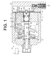
- variable displacement compressor 10 includes a cylinder block 11 and a front housing 12 which is connected to the front end of the cylinder block 11.
- a rear housing 13 is connected to the rear end of the cylinder block 11 through a valve plate 14 and a suction valve forming plate 15.
- the cylinder block 11, the front housing 12 and the rear housing 13 cooperate to form a housing of the variable displacement compressor 10.
- a rotary shaft 16 is rotatably supported by the front housing 12 and the cylinder block 11 through radial- bearings 17, 18, respectively.
- the front housing 12 and the cylinder block 11 cooperate to form a pressure control chamber 121.
- the rotary shaft 16 extends out of the pressure control chamber 121 and is connected to a vehicle engine E that serves as an external drive source for receiving therefrom a driving force.
- a rotary support 19 is fixedly mounted on the rotary shaft 18, and a swash plate 20 that serves as a cam member is supported by the rotary shaft 16 in such a way that it is slidable in the direction of the axis 161 of the rotary shaft 16 and also inclinable relative to the axis 161.
- the rotary shaft 16 is inserted through a hole 201 formed at the center of the swash plate 20 in such a way that the swash plate 20 is slidable along the outer circumferential surface of the rotary shaft 16 through the peripheral wall of the hole 201.
- the swash plate 20 has a support arm 21 formed integrally therewith on the side opposite to the rotary support 19.
- the support arm 21 has a hole 211 extending in the direction perpendicular to the axis 161 of the rotary shaft 16 and a pin 22 is press-fitted in the hole 211.
- the pin 22 has a mid portion 221 which is held and supported by the support arm 21. The swash plate 20 and the support arm 21 cooperate to form a support for the pin 22.
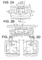
- the pin 22 has guided portions 25, 26 which are formed integral with and on the opposite sides of the mid portion 221, as shown in FIG. 2B.
- the guided portions 25, 26 correspond to first and second ends of the present invention, respectively.
- the guided portion 25 has a guided circumferential surface 251, a conical surface 252 and an end face 253 which are formed in continuity with each other in this order.
- the guided circumferential surface 251 is a convex curved surface that projects outward from the guided portion 25 of the pin 22.
- the boundary between the guided circumferential surface 251 and the conical surface 252 which is designated by numeral 254 is formed by an angled portion in the form of an obtuse angle.
- the guided circumferential surface 251 and the mid portion 221 have formed therebetween an annular recess 223.
- the boundary between the guided circumferential surface 251 and the annular recess 223 which is designated by numeral 255 is formed by an angled portion in the form of an obtuse angle.
- the annular recess 223 facilitates abrasion processing of the guided circumferential surface 251.
- the guided portion 26 has a guided circumferential surface 261, a conical surface 262 and an end face 263 which are formed in continuity with each other in this order.
- the guided circumferential surface 261 is a convex curved surface that projects outward from the guided portion 26 of the pin 22.
- the boundary between the guided circumferential surface 261 and the conical surface 262 which is designated by numeral 264 is formed by an angled portion in the form of an obtuse angle.
- the guided circumferential surface 261 and the mid portion 221 have formed therebetween an annular recess 224.
- the boundary between the guided circumferential surface 261 and the annular recess 224 which is designated by numeral 265 is formed by an angled portion in the form of an obtuse angle.
- the annular recess 224 facilitates abrasion processing of the guided circumferential surface 261.
- the guided circumferential surface 251 extends in the direction of an axis 222 of the pin 22, and besides, the guided circumferential surface 251 is formed by a first convex curve E1 that projects outward from the pin 22.
- the first convex curve E1 is a generatrix of the guided circumferential surface 251.
- the curvature of the first convex curve E1 is set smaller than that of the circle with the same diameter as a diameter of a circle for the guided portion 25 (maximum diameter R1 of circles for the guided circumferential surface 251), and the guided circumferential surface 251 is formed by rotating the generatrix (the first convex curve E1) around the axis 222 of the pin 22.
- the line segment connecting two points on the first convex curve E1 is located inside the guided portion 25.
- FIG. 2D shows an example of the line segment by reference sign L1.
- the guided circumferential surface 261 extends in the direction of the axis 222 of the pin 22, and besides, the guided circumferential surface 261 is formed by a second convex curve E2 that projects outward from the pin 22.
- the second convex curve E2 is a generatrix of the guided circumferential surface 261.
- the curvature of the second convex curve E2 is set smaller than that of the circle with the same diameter as a diameter of a circle for the guided portion 26 (maximum diameter R2 of circles for the guided circumferential surface 261), and the guided circumferential surface 261 is formed by rotating the generatrix (the second convex curve E2) around the axis 222 of the pin 22.
- the line segment connecting two points on the second convex curve E2 is located inside the guided portion 26.
- FIG. 2C shows an example of the line segment by reference sign L2.
- the first convex curve E1 and the second convex curve E2 are arched curve.
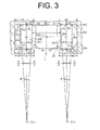
- the guided portion 25 and the guided portion 26 form symmetry of reflection relative to an imaginary plane Y (shown in FIG. 3) which is perpendicular to the axis 222 of the pin 22 in the middle of the axis 222 of the pin 22.
- the radii of curvatures of the first convex curve E1 and the second convex curve E2 are set to be the same, and the diameters R1, R2 of circles for the guided portions 25, 26 are set to be the same.
- the central angle of the first convex curve E1 (the center of the circle for the first convex curve E1 being designated by reference symbol E1 c) is designated by reference symbol ⁇ (whose unit is radian)
- the central angle of the second convex curve E2 (the center of the circle for the second convex curve E2 being designated by reference symbol E2c) is also designated by reference symbol ⁇ .
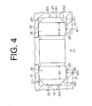
- the rotary support 19 has a pair of guide arms 23, 24 formed integrally therewith on the side opposite to the swash plate 20.
- the guide arms 23, 24 serve as a pair of guide portions of the present invention, respectively.
- the guide arm 23 has a first guide wall 27, a second guide wall 28 and a third guide wall 29 and the guide arm 24 has a fourth guide wall 30, a fifth guide wall 31 and a sixth guide wall 32.
- the first guide wall 27 has a guide plane 271 which is allowed to come in contact with a part of the guided circumferential surface 251 adjacent to the swash plate 20.
- the second guide wall 28 has a guide plane 281 which is allowed to come in contact with a part of the guided circumferential surface 251 adjacent to the rotary support 19.
- the third guide wall 29 has a guide plane 291 which is allowed to come in contact with the end face 253.
- the guide planes 271, 281 are in parallel with each other.
- the guide planes 271, 281, 291 are formed so as to guide the pin 22 in the direction that is perpendicular to the axis 222 of the pin 22 and also in the direction that is inclined from the axis 161 of the rotary shaft 16.
- the third guide wall 29 performs the function of restricting the movement in the direction of the axis 222 of the pin 22.
- the fourth guide wall 30 has a guide plane 301 which is allowed to come in contact with a part of the guided circumferential surface 261 adjacent to the swash plate 20.
- the fifth guide wall 31 has a guide plane 311 which is allowed to come in contact with a part of the guided circumferential surface 261 adjacent to the rotary support 19.
- the sixth guide wall 32 has a guide plane 321 which is allowed to come in contact with the end face 263.
- the guide planes 301, 311, 321 are formed so as to guide the pin 22 in the direction that is perpendicular to the axis 222 of the pin 22 and also in the direction that is inclined from the axis 161 of the rotary shaft 16.
- the sixth guide wall 32 performs the function of restricting the movement in the direction of the axis 222 of the pin 22.
- the guide planes 271, 301 are flush with each other in a plane and the guide planes 281, 311 are flush with each other in a plane which is different from the plane for the guide planes 271, 301.
- the guide planes 271, 301 are in parallel with the guide planes 281, 311.
- the guide arm 23 guides the guided portion 25 and the guide arm 24 guides the guided portion 26.
- the rotary support 19 and the guide arms 23, 24 form a pin guide.
- the length of the width W1 of the guided circumferential surface 251 is set smaller than that of the width W2 of the guide planes 271, 281.
- the width W1 of the guided circumferential surface 251 is incorporated in the width W2 of the guide planes 271, 281.
- the length of the width W3 of the guided circumferential surface 261 is set smaller than that of the width W4 of the guide planes 301, 311.
- the width W3 of the guided circumferential surface 261 is incorporated in the width W4 of the guide planes 301, 311.
- the spacing between the guide plane 271 of the first guide wall 27 and the guide plane 281 of the second guide wall 28 is set larger than the diameter R1 of a circle for the guided circumferential surface 251. That is, there exits a clearance between the guide planes 271, 281 of the first and second guide walls 27, 28 and the guided portion 25.
- the dimension of the minimum clearance C1 (shown in FIG. 3) of this clearance is designated by reference sign Co.
- the spacing between the guide plane 301 of the fourth guide wall 30 and the guide plane 311 of the fifth guide wall 31 is set larger than the diameter R2 of the guided circumferential surface 261. That is, there exits a clearance between the guide planes 301, 311 of the fourth and fifth guide walls 30, 31 and the guided portion 26.
- the dimension of the minimum clearance C2 (shown in FIG. 3),of this clearance is the same as the dimension Co of the minimum clearance C1 (shown in FIG. 3).
- FIG. 3 shows a state of the pin 22 where the guided circumferential surface 251 of the guided portion 25 of the pin 22 indicated by solid line is in contact with the guide plane 281, and besides, the guided circumferential surface 261 of the guided portion 26 of the pin 22 indicated by solid line is in contact with the guide plane 311.
- the state of the pin 22 indicated by solid line in FIG. 3 will be referred to as a non-inclination state of the pin.
- FIG. 3 shows a state of the pin 22 where the guided circumferential surface 251 of the guided portion 25 indicated by chain double-dashed line is in contact with the guide plane 271.
- the guided circumferential surface 261 of the guided portion 26 is in contact with the guide plane 311.
- the pin 22 is inclined by an angle of ⁇ /2. That is, if it is possible to incline the pin 22 counterclockwise by an angle of ⁇ /2 from the non-inclination state of the pin shown in FIG. 3, the point Pe1 (the angled boundary 254) comes in contact with the guide plane 281.
- the pin 22 is inclined by an angle of ⁇ /2. That is, if it is possible to incline the pin 22 clockwise by an angle of ⁇ /2 from the non-inclination state of the pin shown in FIG. 3, the point Pe2 (the angled boundary 264) comes in contact with the guide plane 311.
- Co ⁇ F ⁇ 1 Z + 3 ⁇ W / 2 ⁇ ⁇ / 2 That is, if the angle ⁇ and the dimension Co are set to satisfy the relation of the expression (1), the point P1 does not come in contact with the guide plane 271.
- the angled boundary 264 does not come in edge contact with either of the guide planes 301, 311.
- the torque of the rotary support 19 which is rotatable with the rotary shaft 16 is transmitted to the swash plate 20 through the engagement between the guide plane 291 of the third guide wall 29 of the guide arm 23 and the end face 253 of the guided portion 25 of the pin 22, so that the swash plate 20 is rotated integrally with the rotary shaft 16.
- the guide arms 23, 24, the pin 22 and the support arm 21 cooperate to form a connecting mechanism 39 for connecting the swash plate 20 to the rotary support 19 in such a way that the inclination angle of the swash plate 20 is varied and also that the torque is transmitted from the rotary shaft 16 to the swash plate 20.
- the inclination angle of the swash plate 20 is increased and the maximum inclination angle of the swash plate 20 is regulated by the contact of the swash plate 20 with the rotary support 19.
- the minimum inclination angle of the swash plate 20 is regulated by the contact of the swash plate 20 with a circlip 33 (shown in FIG. 1) mounted on the rotary shaft 16.
- the maximum inclination angle of the swash plate 20 is indicated by solid line and the minimum inclination angle thereof by chain double-dashed line. It is so arranged that the minimum inclination angle of the swash plate 20 is set larger than 0°.
- the cylinder block 11 has formed therethrough a plurality of cylinder bores 111 (only one cylinder bore 111 being shown) and a piston 34 is disposed in each cylinder bore 111.
- the rotary motion of the swash plate 20 is converted into the reciprocating motion of each piston 34 through its corresponding pair of shoes 35 which is engaged with the swash plate 20, and the piston 34 reciprocates in its corresponding cylinder bore 111, accordingly. That is, the piston 34 is operable in conjunction with the rotation of the rotary shaft 16 through the swash plate 20 which is rotated with the rotary shaft 16.
- the rear housing 13 has formed therein a suction chamber 131 and a discharge chamber 132.
- the valve plate 14 has formed therethrough a plurality of suction ports 141 (only one suction port 141 being shown).
- Each of the valve plate 14 and the suction valve forming plate 15 has formed therethrough a plurality of discharge ports 142 (only one discharge port 142 being shown for each).
- the suction valve forming plate 15 has formed thereon a plurality of suction valves 151.
- a discharge valve forming plate 36 is joined to the valve plate 14 and has formed thereon a plurality of discharge valves 361.
- the suction valve 151 is opened and refrigerant gas in the suction chamber 131 is drawn into the corresponding cylinder bore 111.
- the refrigerant gas compressed in the cylinder bore 111 pushes open the discharge valve 361 and is discharged into the discharge chamber 132.
- the opening of the discharge valve 361 is regulated by a retainer 37.
- the discharge chamber 132 and the suction chamber 131 are connected by an external refrigerant circuit (not shown), so that refrigerant discharged from the discharge chamber 132 to the external refrigerant circuit returns to the suction chamber 131.
- the rotary shaft 16 is rotated in the arrow direction Q.
- the swash plate 20 is divided into two halves by an imaginary plane H which extends in the axis 161 of the rotary shaft 16 in perpendicular relation to the axis 222 of the pin 22, one half of the swash plate 20 is located in the region S for the suction stroke and the other half in the region D for the discharge stroke.
- the pistons 34 located in the region S are in the suction stroke and the pistons 34 located in the region D are in the discharge stroke.
- the guided portion 25 of the pin 22 is located in the region S and the guided portion 26 of the pin 22 is located in the region D.
- a thrust bearing 38 is interposed between the rotary support 19 and the front housing 12 for receiving the compressive reaction force which is applied from the refrigerant gas in the cylinder bores 111 to the rotary support 19 through the pistons 34, the shoes 35, the swash plate 20 and the connecting mechanism 39.
- the discharge chamber 132 and the pressure control chamber 121 are connected by a supply passage 40, and the pressure control chamber 121 and the suction chamber 131 are connected by a bleed passage 41. Part of the refrigerant in the discharge chamber 132 is supplied into the pressure control chamber 121 through the supply passage 40 and then flown into the suction chamber 131 through the bleed passage 41.
- An electromagnetically-operated displacement control valve 42 is located in the supply passage 40.
- the amount of refrigerant supplied from the discharge chamber 132 to the pressure control chamber 121 through the supply passage 40 is varied in accordance with the opening of the displacement control valve 42. Since the refrigerant in the pressure control chamber 121 is flown into the suction chamber 131 through the bleed passage 41, the pressure in the pressure control chamber 121 is changed in accordance with the amount of refrigerant supplied from the discharge chamber 132 to the pressure control chamber 121 through the supply passage 40. As the supply of refrigerant increases, the pressure in the pressure control chamber 121 rises. As the supply of refrigerant decreases, the pressure in the pressure control chamber 121 falls. By so controlling the pressure in the pressure control chamber 121, the inclination angle of the swash plate 20 is varied and the displacement of the compressor 10 is varied, accordingly.
- the guided portion 25 is moved along the guide planes 271, 281, 291 and the guided portion 26 along the guide planes 301, 311, 321.
- the first embodiment has the following advantageous effects.
- the middle W31 of the width W3 of the guided circumferential surface 261 is incorporated in the widths of the guide planes 301, 311.
- the guided circumferential surface 251 which faces the angled portion of the end of the guide plane 271 of the guide wall 27 is formed by the convex curved surface, which prevents abrasion caused by edge contact between the guided circumferential surface 251 and the guide plane 271.
- the guided circumferential surface 261 which faces the angled portion of the end of the guide plane 301 of the guide wall 30 is formed by the convex curved surface, which prevents abrasion caused by edge contact between the guided circumferential surface 261 and the guide plane 301.
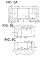
- FIGs. 5A, 5B and 5C The following will describe a third embodiment according to the present invention with reference to FIGs. 5A, 5B and 5C.
- the same reference numerals or symbols of the first embodiment are used for the same parts or elements in the third embodiment.
- the guided portion 25 has a guided circumferential surface 251A in place of the guided circumferential surface 251 of the first embodiment.
- the guided circumferential surface 251A is formed by a first convex curve E3 which includes an arched curve E31, a line segment E32 which is smoothly connected to the arched curve E31, and an arched curve E33 which is smoothly connected to the line segment E32.
- the guided circumferential surface 251A is a convex curved surface formed by rotating the first convex curve E3 around the axis 222 of the pin 22.
- the curvatures of the arched curves E31, E33 are set to be the same, and besides, the curvatures of the arched curves E31, E33 are set smaller than that of the circle with the same diameter as a diameter of a circle for the guided portion 25 (maximum diameter R1 of circles for the guided circumferential surface 251A).
- the line segment connecting one point on the arched curve E31 or E33 and one point on the line segment E32 is located inside the guided portion 25.
- the line segment connecting one point on the arched curve E31 and one point on the arched curve E33 is located inside the guided portion 25.
- the guided portion 26 has a guided circumferential surface 261A in place of the guided circumferential surface 261 of the first embodiment.
- the guided circumferential surface 261A is formed by a second convex curve E4 which includes an arched curve E41, a line segment E42 which is smoothly connected to the arched curve E41, and an arched curve E43 which is smoothly connected to the line segment E42.
- the guided circumferential surface 261A is a convex curved surface formed by rotating the second convex curve E4 around the axis 222 of the pin 22.
- the curvatures of the arched curves E41, E43 are set to be the same, and besides, the curvatures of the arched curves E41, E43 are set smaller than that of the circle with the same diameter as a diameter of a circle for the guided portion 26 (maximum diameter R2 of circles for the guided circumferential surface 261A).
- the line segment connecting one point on the arched curve E41 or E43 and one point on the line segment E42 is located inside the guided portion 26.
- the line segment connecting one point on the arched curve E41 and one point on the arched curve E43 is located inside the guided portion 26.
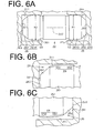
- FIGs. 6A, 6B and 6C The following will describe a fourth embodiment according to the present invention with reference to FIGs. 6A, 6B and 6C.
- the same reference numerals or symbols of the first embodiment are used for the same parts or elements in the fourth embodiment.
- the guided portion 25 has a guided circumferential surface 251 B in place of the guided circumferential surface 251 of the first embodiment.
- the guided circumferential surface 251 B is formed by a first convex curve E5 which includes an arched curve E51 and an arched curve E52 which is smoothly connected to the arched curve E51.
- the curvature of the arched curve E51 is set smaller than that of the arched curve E52, and besides, the curvature of the arched curve E51 is set smaller than that of the circle with the same diameter as a diameter of a circle for the guided portion 25 (maximum diameter R1 of circles for the guided circumferential surface 251B).
- the curvature of the arched curve E52 is set smaller than that of the circle with the same diameter as a diameter of a circle for the guided portion 25 (maximum diameter R1 of circles for the guided circumferential surface 251B).
- the guided circumferential surface 251B is a convex curved surface formed by rotating the first convex curve E5 around the axis 222 of the pin 22.
- the line segment connecting two points on the first convex curve E5 is located inside the guided portion 25.
- the guided portion 26 has a guided circumferential surface 261 B in place of the guided circumferential surface 261 of the first embodiment.
- the guided circumferential surface 261B is formed by a second convex curve E6 which includes an arched curve E61 and an arched curve E62 which is smoothly connected to the arched curve E61.
- the curvature of the arched curve E61 is set smaller than that of the arched curve E62, and besides, the curvature of the arched curve E61 is set smaller than that of the circle with the same diameter as a diameter of a circle for the guided portion 26 (maximum diameter R2 of circles for the guided circumferential surface 261B).
- the curvature of the arched curve E62 is set smaller than that of the circle with the same diameter as a diameter of a circle for the guided portion 26 (maximum diameter R2 of circles for the guided circumferential surface 261B).
- the guided circumferential surface 261B is a convex curved surface formed by rotating the second convex curve E6 around the axis 222 of the pin 22.
- the line segment connecting two points on the second convex curve E6 is located inside the guided portion 26.
- FIGs. 7A and 7B The following will describe a fifth embodiment according to the present invention with reference to FIGs. 7A and 7B.
- the same reference numerals or symbols of the first embodiment are used for the same parts or elements in the fifth embodiment.
- the guided portion 25 has a guided circumferential surface 251D in place of the guided circumferential surface 251 of the first embodiment, which has a cylindrical surface.
- the guided portion 26 has a guided circumferential surface 261D in place of the guided circumferential surface 261 of the first embodiment, which also has a cylindrical surface.
- the first guide wall 27, the second guide wall 28, the fourth guide wall 30 and the fifth guide wall 31 have guide surfaces 272, 282, 302, 312 which are formed by convex curved surface, respectively.
- the guide surface 272 extends in the direction of the axis 222 of the pin 22, and besides, the guide surface 272 is a convex curved surface formed by moving in parallel a convex curve E7 that projects toward the guided portion 25.
- the guide surface 282 extends in the direction of the axis 222 of the pin 22, and besides, the guide surface 282 is a convex curved surface formed by moving in parallel a convex curve E8 that projects toward the guided portion 25.
- the guide surface 302 extends in the direction of the axis 222 of the pin 22, and besides, the guide surface 302 is a convex curved surface formed by moving in parallel a convex curve E9 that projects toward the guided portion 26.
- the guide surface 312 extends in the direction of the axis 222 of the pin 22, and besides, the guide surface 312 is a convex curved surface formed by moving in parallel a convex curve E10 that projects toward the guided portion 26.
- the line segment connecting two points on the convex curve E7 is located inside the first guide wall 27 of the guide arm 23.
- the line segment connecting two points on the convex curve E8 is located inside the second guide wall 28 of the guide arm 23.
- the line segment connecting two points on the convex curve E9 is located inside the fourth guide wall 30 of the guide arm 24.
- the line segment connecting two points on the convex curve E10 is located inside the fifth guide wall 31 of the guide arm 24.
- the guide surfaces 272, 282 prevent edge contact between the guide arm 23 and the pin 22, and besides, the guide surfaces 272, 282 contribute to the reduction of contact pressure in a region of contact between the guided portion 25 and the guide arm 23.
- the guide surfaces 302, 312 prevent edge contact between the guide arm 24 and the pin 22, and besides, the guide surfaces 302, 312 contribute to the reduction of contact pressure in a region of contact between the guided portion 26 and the guide arm 24.
- the swash plate 20 has a pair of guide arms 23C, 24C which are formed integrally therewith.
- the rotary support 19C is formed with an integral support arm 21C.
- the pin 22 is supported by the support arm 21C.
- the guide arm 23C has the first guide wall 27, the second guide wall 28 and the third guide wall 29.
- the guide arm 24C has the fourth guide wall 30, the fifth guide wall 31 and the sixth guide wall 32.
- the guided circumferential surfaces 251, 261 of the guided portions 25, 26 of the pin 22 have the same shape as in the case of the first embodiment.
- the rotary support 19C and the support arm 21C cooperate to form the support for supporting the pin 22.
- the swash plate 20 and the guide arms 23C, 24C cooperate to form the pin guide.
- the guide arms 23C, 24C, the pin 22 and the support arm 21C cooperate to form a connecting mechanism 39C for connecting the swash plate 20 to the rotary support 19C in such a way that the inclination angle of the swash plate 20 is varied and also that the torque is transmitted from the rotary shaft 16 to the swash plate 20.
- the guide surfaces 272, 282, 302, 312 may be formed by using the convex curve of the third embodiment or the convex curve of the fourth embodiment.
- the curvatures of the arched curves E31, E33 may be set larger than that of the circle with the same diameter as a diameter of a circle for the guided portion 25 (maximum diameter R1 of circles for the guided circumferential surface 251A).
Landscapes
- Engineering & Computer Science (AREA)
- Mechanical Engineering (AREA)
- General Engineering & Computer Science (AREA)
- Compressors, Vaccum Pumps And Other Relevant Systems (AREA)
Applications Claiming Priority (1)
| Application Number | Priority Date | Filing Date | Title |
|---|---|---|---|
| JP2006126643A JP2007297978A (ja) | 2006-04-28 | 2006-04-28 | 可変容量型圧縮機 |
Publications (1)
| Publication Number | Publication Date |
|---|---|
| EP1850004A2 true EP1850004A2 (de) | 2007-10-31 |
Family
ID=38328356
Family Applications (1)
| Application Number | Title | Priority Date | Filing Date |
|---|---|---|---|
| EP20070008521 Withdrawn EP1850004A2 (de) | 2006-04-28 | 2007-04-26 | Verdichter mit variabler Verdrängung |
Country Status (2)
| Country | Link |
|---|---|
| EP (1) | EP1850004A2 (de) |
| JP (1) | JP2007297978A (de) |
Cited By (1)
| Publication number | Priority date | Publication date | Assignee | Title |
|---|---|---|---|---|
| CN103016303A (zh) * | 2011-09-21 | 2013-04-03 | 上海三电贝洱汽车空调有限公司 | 变排量斜盘压缩机及其铰链机构的装配方法 |
Families Citing this family (1)
| Publication number | Priority date | Publication date | Assignee | Title |
|---|---|---|---|---|
| JP6079379B2 (ja) * | 2013-03-29 | 2017-02-15 | 株式会社豊田自動織機 | 可変容量型斜板式圧縮機 |
-
2006
- 2006-04-28 JP JP2006126643A patent/JP2007297978A/ja active Pending
-
2007
- 2007-04-26 EP EP20070008521 patent/EP1850004A2/de not_active Withdrawn
Cited By (1)
| Publication number | Priority date | Publication date | Assignee | Title |
|---|---|---|---|---|
| CN103016303A (zh) * | 2011-09-21 | 2013-04-03 | 上海三电贝洱汽车空调有限公司 | 变排量斜盘压缩机及其铰链机构的装配方法 |
Also Published As
| Publication number | Publication date |
|---|---|
| JP2007297978A (ja) | 2007-11-15 |
Similar Documents
| Publication | Publication Date | Title |
|---|---|---|
| EP1323923B1 (de) | Gelenkvorrichtung für einen Taumelscheibenverdichter | |
| EP1850004A2 (de) | Verdichter mit variabler Verdrängung | |
| EP0911522B1 (de) | Schiefscheibenverdichter | |
| US6393964B1 (en) | Compressor having piston rotation restricting structure with lubricating inclined guide surface | |
| JP2000337250A (ja) | 斜板式圧縮機 | |
| EP1850003A2 (de) | Verdichter mit variabler Verdrängung | |
| EP1004769B1 (de) | Taumelscheibenkompressor mit veränderlicher Förderleistung | |
| JP3566125B2 (ja) | 斜板式圧縮機 | |
| JP2024014490A (ja) | 圧縮機 | |
| EP1531266B1 (de) | Kompressor mit veränderlicher Verdrängung | |
| EP1693567A1 (de) | Taumelscheiben-verdichter | |
| JP7028402B2 (ja) | 可変容量圧縮機 | |
| EP1898090A2 (de) | Verdichter mit variabler Verdrängung | |
| US6912948B2 (en) | Swash plate compressor | |
| JP2019218879A (ja) | 往復動式圧縮機の吸入弁構造及び往復動式圧縮機 | |
| CN104334877A (zh) | 容量可变型压缩机 | |
| EP2042731A2 (de) | Taumelscheibenverdichter | |
| US11885319B2 (en) | Swash plate-type compressor | |
| JP2001317453A (ja) | 斜板式圧縮機 | |
| JP2004176652A (ja) | 斜板式圧縮機 | |
| JP3644351B2 (ja) | 可変容量型斜板式圧縮機 | |
| EP1041284A2 (de) | Einlassventil für Kompressor | |
| JP2001132630A (ja) | 容量可変型斜板式圧縮機 | |
| JP2020105950A (ja) | 斜板式液圧回転機械 | |
| JP2006132422A (ja) | 可変容量圧縮機 |
Legal Events
| Date | Code | Title | Description |
|---|---|---|---|
| PUAI | Public reference made under article 153(3) epc to a published international application that has entered the european phase |
Free format text: ORIGINAL CODE: 0009012 |
|
| 17P | Request for examination filed |
Effective date: 20070426 |
|
| AK | Designated contracting states |
Kind code of ref document: A2 Designated state(s): AT BE BG CH CY CZ DE DK EE ES FI FR GB GR HU IE IS IT LI LT LU LV MC MT NL PL PT RO SE SI SK TR |
|
| AX | Request for extension of the european patent |
Extension state: AL BA HR MK YU |
|
| STAA | Information on the status of an ep patent application or granted ep patent |
Free format text: STATUS: THE APPLICATION HAS BEEN WITHDRAWN |
|
| 18W | Application withdrawn |
Effective date: 20120224 |