EP1849940B1 - Dispositif de verrouillage pour une porte coulissante avec des moyens de blocage pour maintenir la porte dans sa position ouverte - Google Patents
Dispositif de verrouillage pour une porte coulissante avec des moyens de blocage pour maintenir la porte dans sa position ouverte Download PDFInfo
- Publication number
- EP1849940B1 EP1849940B1 EP07007966.0A EP07007966A EP1849940B1 EP 1849940 B1 EP1849940 B1 EP 1849940B1 EP 07007966 A EP07007966 A EP 07007966A EP 1849940 B1 EP1849940 B1 EP 1849940B1
- Authority
- EP
- European Patent Office
- Prior art keywords
- lever
- locking device
- pivot axis
- sliding door
- pawl
- Prior art date
- Legal status (The legal status is an assumption and is not a legal conclusion. Google has not performed a legal analysis and makes no representation as to the accuracy of the status listed.)
- Active
Links
- 230000000903 blocking effect Effects 0.000 title 1
- 230000033001 locomotion Effects 0.000 claims description 38
- 238000000034 method Methods 0.000 claims description 13
- 230000009471 action Effects 0.000 claims description 4
- 230000003213 activating effect Effects 0.000 claims description 4
- 230000007246 mechanism Effects 0.000 description 7
- 230000004913 activation Effects 0.000 description 6
- 230000003993 interaction Effects 0.000 description 3
- 230000009849 deactivation Effects 0.000 description 2
- 230000008569 process Effects 0.000 description 2
- 230000008901 benefit Effects 0.000 description 1
- 230000005540 biological transmission Effects 0.000 description 1
- 230000001419 dependent effect Effects 0.000 description 1
- 238000006073 displacement reaction Methods 0.000 description 1
Images


Classifications
-
- E—FIXED CONSTRUCTIONS
- E05—LOCKS; KEYS; WINDOW OR DOOR FITTINGS; SAFES
- E05C—BOLTS OR FASTENING DEVICES FOR WINGS, SPECIALLY FOR DOORS OR WINDOWS
- E05C17/00—Devices for holding wings open; Devices for limiting opening of wings or for holding wings open by a movable member extending between frame and wing; Braking devices, stops or buffers, combined therewith
- E05C17/60—Devices for holding wings open; Devices for limiting opening of wings or for holding wings open by a movable member extending between frame and wing; Braking devices, stops or buffers, combined therewith holding sliding wings open
-
- E—FIXED CONSTRUCTIONS
- E05—LOCKS; KEYS; WINDOW OR DOOR FITTINGS; SAFES
- E05B—LOCKS; ACCESSORIES THEREFOR; HANDCUFFS
- E05B79/00—Mounting or connecting vehicle locks or parts thereof
- E05B79/10—Connections between movable lock parts
- E05B79/20—Connections between movable lock parts using flexible connections, e.g. Bowden cables
-
- E—FIXED CONSTRUCTIONS
- E05—LOCKS; KEYS; WINDOW OR DOOR FITTINGS; SAFES
- E05B—LOCKS; ACCESSORIES THEREFOR; HANDCUFFS
- E05B85/00—Details of vehicle locks not provided for in groups E05B77/00 - E05B83/00
- E05B85/20—Bolts or detents
- E05B85/24—Bolts rotating about an axis
- E05B85/26—Cooperation between bolts and detents
-
- E—FIXED CONSTRUCTIONS
- E05—LOCKS; KEYS; WINDOW OR DOOR FITTINGS; SAFES
- E05C—BOLTS OR FASTENING DEVICES FOR WINGS, SPECIALLY FOR DOORS OR WINDOWS
- E05C17/00—Devices for holding wings open; Devices for limiting opening of wings or for holding wings open by a movable member extending between frame and wing; Braking devices, stops or buffers, combined therewith
- E05C17/02—Devices for holding wings open; Devices for limiting opening of wings or for holding wings open by a movable member extending between frame and wing; Braking devices, stops or buffers, combined therewith by mechanical means
- E05C17/46—Devices for holding wings open; Devices for limiting opening of wings or for holding wings open by a movable member extending between frame and wing; Braking devices, stops or buffers, combined therewith by mechanical means in which the wing or a member fixed thereon is engaged by a movable fastening member in a fixed position; in which a movable fastening member mounted on the wing engages a stationary member
- E05C17/48—Devices for holding wings open; Devices for limiting opening of wings or for holding wings open by a movable member extending between frame and wing; Braking devices, stops or buffers, combined therewith by mechanical means in which the wing or a member fixed thereon is engaged by a movable fastening member in a fixed position; in which a movable fastening member mounted on the wing engages a stationary member comprising a sliding securing member
-
- E—FIXED CONSTRUCTIONS
- E05—LOCKS; KEYS; WINDOW OR DOOR FITTINGS; SAFES
- E05B—LOCKS; ACCESSORIES THEREFOR; HANDCUFFS
- E05B81/00—Power-actuated vehicle locks
- E05B81/12—Power-actuated vehicle locks characterised by the function or purpose of the powered actuators
- E05B81/14—Power-actuated vehicle locks characterised by the function or purpose of the powered actuators operating on bolt detents, e.g. for unlatching the bolt
Definitions
- the present invention relates to locking devices for a sliding door with locking means for fixing the open sliding door and method for actuating locking means for fixing an open sliding door of a motor vehicle.
- the invention finds particular application in automobiles, especially passenger cars and trucks.
- the sliding door of a motor vehicle moves between two end positions, in which a door opening is closed or opened by the sliding door, substantially parallel to the side surface of the motor vehicle.
- a corresponding sliding door is arranged for example between the so-called B-pillar and the so-called C-pillar on at least one side of a motor vehicle and has at least one designated as a main lock lock unit, preferably on the rear in the direction of travel door front wall.
- This is usually a door lock with locking mechanism of the catch and pawl and at least one locking lever, preferably a central locking lever and / or at least one actuating lever, optionally with a release lever, and / or installed on the vehicle body striker or shooting bolt, which after the Falling of the catch when closing the door is covered by this.
- a free movement of the sliding door is to be prevented both in the closed and in the fully open position. While in the closed state, the mobility can be prevented by the door lock, a so-called door lock with the sliding door in the open state cooperate to prevent an independent method of the sliding door.
- Such an independent method of sliding door could without a such door lock z. B. occur when parking the vehicle in parallel to the direction of the vehicle running high angle, which might be in or out of people at risk.
- From the DE 100 00 639 A1 is an actuator for a sliding door, in particular of motor vehicles, with a door lock, a form-locking lockable latching device for holding the sliding door in its open position and a door inside operation with a door inside handle and a door outside operation with an outside door handle, the door lock and the locking device via fasteners mechanically the door handles are actuated and in the door lock, the logical functions for locking / unlocking the sliding door are realized.
- a closing device for a sliding door is to be specified, with which the locking means for fixing the opened sliding door can be actuated particularly comfortably.
- a method is to be specified, with which the safe opening and closing of the sliding door is made possible without the need for a considerably higher power requirement on the part of the operator of the sliding door.
- the closing device mentioned here is, in particular, the door lock of a sliding door with which the sliding door can usually be fixed to the bodywork of a motor vehicle.
- a sliding door usually only has one locking means, but this is not absolutely necessary.
- known door retainers may also be considered as locking means.
- the activation or (de-) activation of this locking means is considered by means of actuating an adapted door lock or an adapted locking device for locking or unlocking the sliding door.
- the locking device initially comprises a rotary latch, which hereby regularly means the component of a locking device which cooperates with the striker or locking bolt.
- the rotary latch regularly defines a plurality of closed states, such as the open state when the latch bolt is released, a so-called pre-latch position and a main latch position when the latch cooperates with the striker, on the one hand, and the pawl, on the other hand.
- This rotary latch is now positioned on a first pivot axis, wherein the rotary latch is in particular so spring loaded that its preferred position is the open position.
- the pawl serves to lock the rotary latch, so that it is fixed with respect to at least one direction of rotation.
- the pawl is positioned on a second pivot axis, which is spaced from the first pivot axis.
- This second pivot axis can be driven by itself, but is preferably the variant in which the second pivot axis is used only for supporting the components positioned there and the pawl directly mechanically (and / or electric motor assisted) can be moved around the second pivot axis.
- the pivot axis or the pawl is connected to a corresponding handling element.
- Such handling elements may be, for example, components and / or drives, which cooperate in particular with handles of the sliding door on the inside and / or the outside.
- This pawl regularly pivots not arbitrarily far but within a predetermined pivoting range, which in particular is only so large that the pawl can be lifted from the catch.
- the actuating lever is advantageously connected to a connecting element of the locking means, for example a linkage and / or a Bowden cable. This creates in particular the possibility that the actual locking mechanism is positioned further away from the locking device. However, the movements performed with the actuating lever to be transmitted to this locking mechanism, for example, the linkage and / or the Bowden cable is helpful.
- the actuating lever is at least partially movable by the catch and at least partially by the pawl and / or a reset lever and wherein the movement of the actuating lever by the catch and the movement of the actuating lever by the pawl and / or the reset lever was done separately ,
- that means that the movement of the actuating lever is at least partially (preferably completely) decoupled, on the one hand, from the rotary latch and, on the other hand, from the pawl and / or the reset lever. It is particularly preferred that the transmitted via the handling element on the pawl movement when Opening and closing the locking device is not affected by the activation or deactivation of the locking means, so for the operator no increased effort is required. This is achieved in particular by the fact that the movement of the actuating lever during opening and closing of the closing device is taken over by the rotary latch, so that the movements of the handling element or the pawl, which are simultaneously accompanied, take place in an almost force-free idle stroke (apart from a few frictional forces which overcome this become).
- the greater proportion of the movement of the actuating lever is controlled by the rotary latch, wherein the time for the movements of the actuating lever by the pawl and / or the locking pin and / or further (in particular electric motor assisted) components of the closing device is determined ,
- the proposed here embodiment of the locking device has the advantage that for activating or deactivating such a door arrester or the locking means on the existing sliding door lock actuation system is easy to handle, with no significant additional operating forces occur by the operating comfort could be affected.
- the actuating lever has a first driver for interacting with a component of the first pivot axis and a second driver for interacting with a component of the second pivot axis.
- the component of the first pivot axis is in particular the already explained rotary latch, which is partially rotatable relative to the actuating lever.
- the actuating lever on a second carrier which with the pawl and / or another, positioned on the second pivot axis component (which is driven in substantially the same manner as the pawl and / or with this partially connected against rotation) cooperates.
- the first driver and the second driver are formed with respect to the first pivot axis on which the actuating lever opposite.
- the actuating lever has substantially three arms, wherein a first arm for the first driver, a second arm for connection to the locking means and a third arm is provided with the second driver. It is very particularly preferred to select the position of the first and second drivers with respect to the first pivot axis such that they are formed at different distances from the pivot axis. In this way, by means of suitable connecting elements, a particularly coordinated introduction of force onto the actuating lever can be realized taking into account the prevailing space conditions.
- a locking device in which the rotary latch is formed with a projection which cooperates with the first catch during part of the rotation of the rotary latch.
- the actuating lever and rotary latch on the first pivot axis are arranged directly above one another. It is advantageous if the projection of the rotary latch extends in the direction of the actuating lever, wherein the driver can be brought at least partially on the periphery of the plant.
- the projection is formed in the manner of a pin, pins and / or stop.
- the first driver preferably abuts against the at least one projection of the rotary latch.
- the reset lever is positioned on the second pivot axis, which cooperates with the second catch during at least part of the rotation of the reset lever.
- the catch and pawl are substantially in one plane, wherein the first driver and the projection and optionally also the second driver and a reset lever are in one plane.
- the reset lever is advantageously driven as well as the pawl on the second pivot axis, wherein, if necessary, a margin between the return lever and the pawl is provided.
- certain forces and / or lever lengths can be set to realize a certain Verschwenkweges the actuating lever.
- the interaction of the second driver with the reset lever takes place in particular during the deactivation of the locking means and / or at the beginning of the closing of the sliding door from the open position.
- the return lever is movable independently of the pawl by means of the handling element.
- the possibility of (partially) separate control of pawl and reset lever is opened at the second pivot axis, so that, if necessary, child locks or similar locks are provided upon actuation of the handling element of the inside or outside.
- a movement of the actuating lever in a direction of rotation is effected by means of a force acting on the first driver and the second driver.
- the rotary latch and the locking means are spring-biased in the same direction in the closed state.
- the movement of the rotary latch from a closed to an open position is assisted by a corresponding spring.
- the first driver is released, so that the locking means are transferred at a corresponding spring bias in the activated or the fixed state, without requiring further effort of the operator of the sliding door.
- a movement of the actuating lever of different magnitude is effected by the action of force on the first driver and the second driver.
- a reset lever With regard to the execution of a reset lever is preferred that this is designed in several parts, wherein a first lever part is positioned on the second pivot axis and cooperates with a second lever part, which is positioned a third pivot axis and is movable with the first lever part, that it is contactable with the second driver.
- a kind of rocker is formed with the second lever part, which is controllable via the first lever part.
- the length of the two members of the second lever part may be adjusted taking into account the required torque transmission. As a result, a rotation of the first lever part can be performed with very low actuating forces, which is transmitted via the second lever part to the second driver of the actuating lever.
- this multi-part return lever reference is made in particular to the description of the figures.
- step a it is preferred that this is initiated when the locking device is unlocked by means of a handling element for the locking pawl.
- the operating chain internal operating lever / external operating lever, optionally electrically opening lever for electrically assisted opening, etc.
- the pawl is lifted off the rotary latch.
- the pawl is pivoted, for example, as a result of a corresponding spring bias in the open position.
- the projection of the rotary latch is removed from the first driver of the actuating lever, so that the first driver is released and the locking means are transferred to an active state.
- the locking means comprise elements which engage non-positively and / or positively with components of the motor vehicle, in particular with a guide rail of the sliding door or other body components of the motor vehicle.
- step c) it is preferred that this is initiated at the beginning of a closing operation of the sliding door by means of a handle element for the pawl.
- a movement of the locking means is caused in particular by the rotation of the pawl or positioned on the same second pivot axis return lever, so that the force and / or positive connection is eliminated.
- the locking means are not transferred into the same state as in the case of the closing device in the closed state (in particular the so-called main catch).
- step c the following aspects are also advantageous for a high degree of operating comfort: Since in this state the pawl is regularly in a (compared to the main catch) deflected position, a Leerhub is initially made when operating the handling element until a movement of the pawl begins. In order to reduce one of the expenditure of force when actuating the handling element, it is now proposed that the movement of a reset lever to release the locking means take place at most until the pawl is moved along. As a result of the avoidance of a simultaneous movement of the return lever and pawl during step c), thus the comfort can be further improved.
- step d) is initiated when the locking device is locked. It is meant in particular that the rotation of the rotary latch when interacting with the striker on the motor vehicle or the so-called B-pillar and / or other body parts of the motor vehicle is largely carried out.
- This actual closing operation can be assisted by an electric motor, for example in which the rotary latch rotates supported by an electric motor, so that the additional forces for deactivating the locking means do not have to be applied via the handling element of the operator.
- the free space for the movements on the components on the second pivot axis can be provided in order to allow a substantially "powerless" lifting of the pawl from the rotary latch.
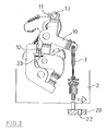
- Fig. 1 illustrates a preferred embodiment of the locking device 1, wherein the movement of the components when unlocking the locking or the activation of the locking means is explained.
- the illustrated rotary latch 4 In the illustrated state of the closure device 1, which is also referred to as the closed state, the illustrated rotary latch 4 is in engagement with a striker (not shown) of a motor vehicle. This state is now changed by mechanically and / or electromotively supported by means of a handling element 8, the pawl 6 is lifted from the rotary latch 4 in the direction of the arrow drawn in black. It must essentially only the frictional forces between the rotary latch 4 and pawl 6 are overcome, the pawl 6 is pivoted about a predetermined pivoting area 9 about the second pivot axis 7 around.
- Fig. 2 Now, the state of the closing device 1 is illustrated, in which, for example, a displacement of the sliding door 2 takes place.
- the locking means 3 are now positioned, for example with respect to the motor vehicle 20 under the body so that they are moved in the process towards an engagement device 22. Now reaches the sliding door 2, the fully open position, the locking means 3 engages in the engagement device 22 a. For this additional movement of the locking means 3 is sufficient space 23 in the region of the first driver 11 and the second driver 12 of the actuating lever 10 is provided. For a secure engagement of the locking means 3 is ensured in the engagement device 22.
- the state of the closing device in the fully open position of the sliding door 2 illustrates the Fig. 3 , wherein the movements indicated by the arrows now show the operations of releasing the locking means 3.
- the locking means 3 are in engagement with the engagement device 22.
- the handling element 8 is now actuated again, the components, which cooperate with the second pivot axis 7, cause the lifting. Accordingly, therefore, the handling element 8 is moved mechanically and / or electromotively supported, so that again the pawl 6 and / or a second pivot axis 7 driven return lever 14 is moved (indicated by a black arrow).
- the reset lever 14 is constructed with a first lever part 17 and a second lever part 18, which is arranged about a third pivot axis 19.
- the movement of the pawl 6 and the first lever part 17 of the reset lever 14 is transmitted via a correspondingly shaped stop on the second lever member 18, which is similar to a rocker now deflected about the third pivot axis 19. It is preferred that the second lever part 18 at the beginning of its movement is already in contact with the second driver 12, so that a small pivoting range leads to a sufficient stroke with respect to the locking means 3.
- the rotation of the actuating lever 10 in the direction of rotation 15 is realized in the rule only over a small extent 16, so that the forces and / or paths required for this purpose are low. Particularly preferably, the extent corresponds to 16 maximum space 23, so that for this movement, the pawl 6, which rests against the rotary latch 4 for this movement, does not have to be moved.
- This movement mechanism is in particular set by operating the door inside and / or outside door handle of the sliding door in the fully open position in motion.
- the activating means 3 are again in an active state, so that again a secure engagement in the engagement means 22 is ensured with a renewed opening.
- the closing operation of the closing device 1 commences, at the same time the locking means 3 being deactivated.
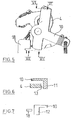
- the corresponding movements are based on Fig. 4 explained.
- a rotation of the rotary latch 4 is again caused, this time counterclockwise, as illustrated by the black arrow.
- the projection 13 of the rotary latch 4 is brought into contact with the first driver 11 of the actuating lever 10, so that the actuating lever 10 is pivoted in the direction of rotation 15.
- the locking means 3 and their point of attack on the operating lever 10 are moved by a further extent 16.
- Fig. 5 shows a further embodiment of the locking device, wherein the contact areas of the actuating lever 10 are modified with the rotary latch 4 and the second lever member 18.
- the actuating lever 10 has a first driver 11, which extends into the plane of the rotary latch 4 extends into and can be brought into contact with a (extending in the circumferential direction) projection 13 of the rotary latch 4 in contact.
- a protruding from the plane of the rotary latch 4 projection 13 of the rotary latch 4 (such as in Fig. 2 shown) omitted. become.
- the actuating lever 10 may additionally be provided with a protruding from the plane of the actuating lever 10 second driver 12 for cooperation with the second lever member 18, for example, as in Fig. 7 is illustrated. Preferably then both drivers of the actuating lever 10 extend in the same direction, but this is not absolutely necessary. This illustrated embodiment of the actuating lever 10 may require lower adjustments of the other components of the locking device, wherein the interaction with these components essentially proceeds as previously shown.
Landscapes
- Engineering & Computer Science (AREA)
- Mechanical Engineering (AREA)
- Lock And Its Accessories (AREA)
Claims (14)
- Dispositif de fermeture (1) pour une porte coulissante (2), avec des moyens de blocage (3) destinés à fixer la porte coulissante (2) ouverte, comportant au moins les composants suivants :- un loquet rotatif (4) qui est positionné sur un premier axe de pivotement (5),- un cliquet d'arrêt (6) qui est positionné sur un deuxième axe de pivotement (7) et qui à l'aide d'un élément de manipulation (8) est mobile dans une plage de pivotement (9) et- un levier de manoeuvre (10) qui est positionné sur le premier axe de pivotement (5) et qui est relié avec le moyen de blocage (3),le levier de manoeuvre (10) étant déplaçable au moins en partie par le loquet rotatif (4) et au moins en partie par le cliquet d'arrêt (6) et/ou par un levier de rappel (14) et le déplacement du levier de manoeuvre (10) par le loquet rotatif (4), ainsi que le déplacement du levier de manoeuvre (10) par le cliquet d'arrêt (6) et/ou le levier de rappel (14) s'effectuant séparément.
- Dispositif de fermeture (1) selon la revendication 1, sur lequel le levier de manoeuvre (10) comporte un premier entraîneur (11) destiné à coopérer avec un composant du premier axe de pivotement (5) et un deuxième entraîneur (12) destiné à coopérer avec un composant du deuxième axe de pivotement (7).
- Dispositif de fermeture (1) selon la revendication 2, sur lequel le loquet rotatif (4) est conçu avec une saillie (13) qui pendant une partie de la rotation du loquet rotatif (4) coopère avec le premier entraîneur (11).
- Dispositif de fermeture (1) selon l'une quelconque des revendications 2 ou 3, sur lequel le levier de rappel (14) est positionné sur le deuxième axe de pivotement (7), le levier de rappel (14) coopérant pendant au moins une partie de la rotation du levier de rappel (14) avec le deuxième entraîneur (12).
- Dispositif de fermeture (1) selon l'une quelconque des revendications 2 à 4, sur lequel par l'action d'une force sur le premier entraîneur (11) et sur le deuxième entraîneur (12), il est provoqué un déplacement du levier de manoeuvre (10) dans une direction de rotation (15).
- Dispositif de fermeture (1) selon l'une quelconque des revendications précédentes, sur lequel en position fermée, le loquet rotatif (4) et les moyens de blocage (3) sont contraints par ressort dans la même direction.
- Dispositif de fermeture (1) selon l'une quelconque des revendications 2 à 5, sur lequel par l'action d'une force sur le premier entraîneur (11) et sur le deuxième entraîneur (12), il est provoqué un déplacement du levier de manoeuvre (10) de différente étendue (16).
- Dispositif de fermeture (1) selon l'une quelconque des revendications 2 à 5 ou 7 précédentes, sur lequel le levier de rappel (14) est conçu en plusieurs parties, une première partie (17) de levier étant positionnée sur le deuxième axe de pivotement (7) et coopérant avec une deuxième partie (18) de levier qui est positionnée sur un troisième axe de pivotement (19) et qui avec la première partie (17) de levier est déplaçable de sorte à pouvoir entrer en contact avec le deuxième entraîneur (12).
- Dispositif de fermeture (1) selon l'une quelconque des revendications 4 à 8, sur lequel le levier de rappel (14) est déplaçable indépendamment du cliquet de blocage (6) au moyen de l'élément de manipulation (8).
- Véhicule automobile (20) comprenant une porte coulissante (2) avec un dispositif de fermeture (1) selon l'une quelconque des revendications 1 à 9.
- Procédé destiné à manoeuvrer des moyens de blocage (3) pour fixer une porte coulissante (2) ouverte d'un véhicule automobile (20), comprenant au moins les étapes suivantes :a) l'activation des moyens de blocage (3) à l'aide d'un levier de manoeuvre (10) positionné sur le premier axe de pivotement (5) suite à une rotation d'un loquet rotatif (4), positionné sur le premier axe de pivotement (5), d'un dispositif de fermeture (1) selon l'une quelconque des revendications 1 à 9 pour la porte coulissante (2),b) la fixation de la porte coulissante (2) sur le véhicule automobile (20) à l'atteinte de la position ouverte avec le moyen de blocage (3) ;c) le détachement des moyens de blocage (3) avec le levier de manoeuvre (10) suite à une rotation d'un cliquet d'arrêt (6) ou d'un composant supplémentaire du dispositif de fermeture (1), est relié avec ce dernier ;d) la désactivation des moyens de blocage (3) suite à une rotation du loquet rotatif (4).
- Procédé selon la revendication 11, lors duquel l'étape a) est initiée lors du déblocage du dispositif de fermeture (1) au moyen d'un élément de manipulation (8) pour le cliquet de blocage (6).
- Procédé selon la revendication 11 ou 12, lors duquel l'étape c) est initiée au début d'un processus de fermeture de la porte coulissante (2) au moyen d'un élément de manipulation (8) pour le cliquet de blocage (6).
- Procédé selon l'une quelconque des revendications 11 à 13, lors duquel l'étape d) est initiée lors du verrouillage du dispositif de fermeture (1).
Applications Claiming Priority (2)
| Application Number | Priority Date | Filing Date | Title |
|---|---|---|---|
| DE102006020284 | 2006-04-27 | ||
| DE102006053133A DE102006053133A1 (de) | 2006-04-27 | 2006-11-10 | Schließvorrichtung für eine Schiebetür mit Arretierungsmitteln sowie Verfahren zum Betätigen von Arretierungsmitteln einer Schiebetür |
Publications (3)
| Publication Number | Publication Date |
|---|---|
| EP1849940A2 EP1849940A2 (fr) | 2007-10-31 |
| EP1849940A3 EP1849940A3 (fr) | 2012-07-18 |
| EP1849940B1 true EP1849940B1 (fr) | 2016-10-12 |
Family
ID=38512127
Family Applications (1)
| Application Number | Title | Priority Date | Filing Date |
|---|---|---|---|
| EP07007966.0A Active EP1849940B1 (fr) | 2006-04-27 | 2007-04-19 | Dispositif de verrouillage pour une porte coulissante avec des moyens de blocage pour maintenir la porte dans sa position ouverte |
Country Status (1)
| Country | Link |
|---|---|
| EP (1) | EP1849940B1 (fr) |
Families Citing this family (3)
| Publication number | Priority date | Publication date | Assignee | Title |
|---|---|---|---|---|
| JP5668468B2 (ja) * | 2010-12-28 | 2015-02-12 | アイシン精機株式会社 | 車両用ドアロック装置 |
| DE102019131179A1 (de) * | 2019-11-19 | 2021-05-20 | Kiekert Aktiengesellschaft | Kraftfahrzeug-Schloss |
| AT523271B1 (de) * | 2019-12-19 | 2021-07-15 | Blum Gmbh Julius | Führungsanordnung zur Führung wenigstens eines bewegbaren Möbelteils |
Family Cites Families (5)
| Publication number | Priority date | Publication date | Assignee | Title |
|---|---|---|---|---|
| DE9302707U1 (de) * | 1993-02-25 | 1994-06-30 | Ed. Scharwächter GmbH + Co KG, 42855 Remscheid | Türschließeinrichtung für Kraftwagentüren |
| FR2793275B1 (fr) * | 1999-05-04 | 2001-06-29 | Valeo Securite Habitacle | Dispositif de fermeture pour une portiere laterale de vehicule automobile et vehicule equipe de ce dispositif |
| DE10000639B4 (de) * | 2000-01-11 | 2005-05-04 | Siemens Ag | Betätigungsvorrichtung für Schiebetür |
| KR100470630B1 (ko) * | 2002-11-02 | 2005-02-21 | 기아자동차주식회사 | 파워 슬라이딩 도어 개폐시스템 |
| DE102004022826A1 (de) * | 2004-05-06 | 2005-12-01 | Iav Gmbh Ingenieurgesellschaft Auto Und Verkehr | Vorrichtung zur Verriegelung einer Fahrzeugschiebetür |
-
2007
- 2007-04-19 EP EP07007966.0A patent/EP1849940B1/fr active Active
Also Published As
| Publication number | Publication date |
|---|---|
| EP1849940A3 (fr) | 2012-07-18 |
| EP1849940A2 (fr) | 2007-10-31 |
Similar Documents
| Publication | Publication Date | Title |
|---|---|---|
| EP3612695B1 (fr) | Serrure de véhicule automobile | |
| EP3221182B1 (fr) | Dispositif de verrouillage, servant en particulier à verrouiller un dossier d'un siège de véhicule comprenant une structure de véhicule | |
| EP3612697B1 (fr) | Serrure pour véhicule à moteur | |
| EP1854945B1 (fr) | Système de verrouillage pour une porte d'un véhicule automobile avec plusieurs éléments de verrouillage et une unité de contrôle commune | |
| EP1724423B1 (fr) | Serrure de véhicule automobile et dispositif de retenue pour un dispositif de sécurité d'un véhicule | |
| DE202006012091U1 (de) | Kraftfahrzeugschloß | |
| DE102008028255B4 (de) | Schließvorrichtung | |
| EP3987136B1 (fr) | Équipement de fermeture pour un véhicule automobile | |
| EP3060735A1 (fr) | Serrure de portière de véhicule automobile | |
| WO2020048653A1 (fr) | Ensemble poignée de porte conçu pour un véhicule automobile | |
| DE102011108438A1 (de) | Kraftfahrzeugschloss | |
| EP1849940B1 (fr) | Dispositif de verrouillage pour une porte coulissante avec des moyens de blocage pour maintenir la porte dans sa position ouverte | |
| DE102004032147A1 (de) | Schloss eines bewegbaren Elements einer Fahrzeugkarosserie | |
| WO2023030982A1 (fr) | Dispositif de fixation pour un battant ou un couvercle d'un véhicule | |
| EP3418478A1 (fr) | Serrure de véhicule automobile | |
| WO2017220078A1 (fr) | Système de fermeture de véhicule | |
| DE102006053133A1 (de) | Schließvorrichtung für eine Schiebetür mit Arretierungsmitteln sowie Verfahren zum Betätigen von Arretierungsmitteln einer Schiebetür | |
| EP3870785B1 (fr) | Serrure de véhicule automobile, en particulier serrure de porte de véhicule automobile | |
| DE102017101703A1 (de) | Schloss mit Zuzieheinrichtung für ein Kraftfahrzeug | |
| EP3059361B1 (fr) | Serrure de véhicule automobile | |
| DE102008021923A1 (de) | Schließsystem für ein B-Säulen-freies Fahrzeug | |
| EP2518244B1 (fr) | Agencement de poignée de porte | |
| DE102009033154B4 (de) | Sperrvorrichtung für ein Fahrzeugtürschloss | |
| DE10362118B4 (de) | Reversiermechanik für eine Vorrichtung zum reversiblen Aufstellen einer Fahrzeug-Tür | |
| DE10301208B4 (de) | Motorhaubenverschluss |
Legal Events
| Date | Code | Title | Description |
|---|---|---|---|
| PUAI | Public reference made under article 153(3) epc to a published international application that has entered the european phase |
Free format text: ORIGINAL CODE: 0009012 |
|
| AK | Designated contracting states |
Kind code of ref document: A2 Designated state(s): AT BE BG CH CY CZ DE DK EE ES FI FR GB GR HU IE IS IT LI LT LU LV MC MT NL PL PT RO SE SI SK TR |
|
| AX | Request for extension of the european patent |
Extension state: AL BA HR MK YU |
|
| RAP1 | Party data changed (applicant data changed or rights of an application transferred) |
Owner name: KIEKERT AKTIENGESELLSCHAFT |
|
| PUAL | Search report despatched |
Free format text: ORIGINAL CODE: 0009013 |
|
| AK | Designated contracting states |
Kind code of ref document: A3 Designated state(s): AT BE BG CH CY CZ DE DK EE ES FI FR GB GR HU IE IS IT LI LT LU LV MC MT NL PL PT RO SE SI SK TR |
|
| AX | Request for extension of the european patent |
Extension state: AL BA HR MK RS |
|
| RIC1 | Information provided on ipc code assigned before grant |
Ipc: E05C 17/48 20060101ALI20120614BHEP Ipc: E05C 17/60 20060101ALI20120614BHEP Ipc: E05B 65/08 20060101AFI20120614BHEP Ipc: E05B 65/20 20060101ALI20120614BHEP |
|
| 17P | Request for examination filed |
Effective date: 20130103 |
|
| AKX | Designation fees paid |
Designated state(s): DE |
|
| 17Q | First examination report despatched |
Effective date: 20130313 |
|
| REG | Reference to a national code |
Ref country code: DE Ref legal event code: R079 Ref document number: 502007015176 Country of ref document: DE Free format text: PREVIOUS MAIN CLASS: E05B0065080000 Ipc: E05B0085260000 |
|
| RIC1 | Information provided on ipc code assigned before grant |
Ipc: E05C 17/60 20060101ALI20160314BHEP Ipc: E05B 85/26 20140101AFI20160314BHEP Ipc: E05B 79/20 20140101ALI20160314BHEP Ipc: E05C 17/48 20060101ALI20160314BHEP Ipc: E05B 81/14 20140101ALN20160314BHEP |
|
| GRAP | Despatch of communication of intention to grant a patent |
Free format text: ORIGINAL CODE: EPIDOSNIGR1 |
|
| INTG | Intention to grant announced |
Effective date: 20160429 |
|
| GRAS | Grant fee paid |
Free format text: ORIGINAL CODE: EPIDOSNIGR3 |
|
| GRAA | (expected) grant |
Free format text: ORIGINAL CODE: 0009210 |
|
| AK | Designated contracting states |
Kind code of ref document: B1 Designated state(s): DE |
|
| REG | Reference to a national code |
Ref country code: DE Ref legal event code: R096 Ref document number: 502007015176 Country of ref document: DE |
|
| REG | Reference to a national code |
Ref country code: DE Ref legal event code: R097 Ref document number: 502007015176 Country of ref document: DE |
|
| PLBE | No opposition filed within time limit |
Free format text: ORIGINAL CODE: 0009261 |
|
| STAA | Information on the status of an ep patent application or granted ep patent |
Free format text: STATUS: NO OPPOSITION FILED WITHIN TIME LIMIT |
|
| 26N | No opposition filed |
Effective date: 20170713 |
|
| P01 | Opt-out of the competence of the unified patent court (upc) registered |
Effective date: 20230529 |
|
| PGFP | Annual fee paid to national office [announced via postgrant information from national office to epo] |
Ref country code: DE Payment date: 20240418 Year of fee payment: 18 |