EP1849583A2 - Vorrichtung zum Bearbeiten von Werkstücken mittels Ultraschall - Google Patents
Vorrichtung zum Bearbeiten von Werkstücken mittels Ultraschall Download PDFInfo
- Publication number
- EP1849583A2 EP1849583A2 EP07001813A EP07001813A EP1849583A2 EP 1849583 A2 EP1849583 A2 EP 1849583A2 EP 07001813 A EP07001813 A EP 07001813A EP 07001813 A EP07001813 A EP 07001813A EP 1849583 A2 EP1849583 A2 EP 1849583A2
- Authority
- EP
- European Patent Office
- Prior art keywords
- recess
- punch
- workpiece
- sonotrode
- plunger
- Prior art date
- Legal status (The legal status is an assumption and is not a legal conclusion. Google has not performed a legal analysis and makes no representation as to the accuracy of the status listed.)
- Granted
Links
- 238000002604 ultrasonography Methods 0.000 title claims abstract description 14
- 238000003754 machining Methods 0.000 title description 7
- 239000012530 fluid Substances 0.000 claims abstract description 11
- 238000004080 punching Methods 0.000 claims description 4
- 238000006073 displacement reaction Methods 0.000 claims 1
- 230000010355 oscillation Effects 0.000 abstract 1
- 230000000284 resting effect Effects 0.000 abstract 1
- 238000013016 damping Methods 0.000 description 5
- 238000003466 welding Methods 0.000 description 2
- 239000000919 ceramic Substances 0.000 description 1
- 230000001419 dependent effect Effects 0.000 description 1
- 230000000694 effects Effects 0.000 description 1
- 238000010438 heat treatment Methods 0.000 description 1
- 239000007788 liquid Substances 0.000 description 1
- 239000000463 material Substances 0.000 description 1
- 239000002184 metal Substances 0.000 description 1
- 238000000465 moulding Methods 0.000 description 1
- 239000004033 plastic Substances 0.000 description 1
- 238000003825 pressing Methods 0.000 description 1
- 230000000717 retained effect Effects 0.000 description 1
- 238000003860 storage Methods 0.000 description 1
Images
Classifications
-
- B—PERFORMING OPERATIONS; TRANSPORTING
- B26—HAND CUTTING TOOLS; CUTTING; SEVERING
- B26D—CUTTING; DETAILS COMMON TO MACHINES FOR PERFORATING, PUNCHING, CUTTING-OUT, STAMPING-OUT OR SEVERING
- B26D7/00—Details of apparatus for cutting, cutting-out, stamping-out, punching, perforating, or severing by means other than cutting
- B26D7/08—Means for treating work or cutting member to facilitate cutting
- B26D7/086—Means for treating work or cutting member to facilitate cutting by vibrating, e.g. ultrasonically
-
- B—PERFORMING OPERATIONS; TRANSPORTING
- B23—MACHINE TOOLS; METAL-WORKING NOT OTHERWISE PROVIDED FOR
- B23K—SOLDERING OR UNSOLDERING; WELDING; CLADDING OR PLATING BY SOLDERING OR WELDING; CUTTING BY APPLYING HEAT LOCALLY, e.g. FLAME CUTTING; WORKING BY LASER BEAM
- B23K20/00—Non-electric welding by applying impact or other pressure, with or without the application of heat, e.g. cladding or plating
- B23K20/10—Non-electric welding by applying impact or other pressure, with or without the application of heat, e.g. cladding or plating making use of vibrations, e.g. ultrasonic welding
- B23K20/106—Features related to sonotrodes
-
- B—PERFORMING OPERATIONS; TRANSPORTING
- B29—WORKING OF PLASTICS; WORKING OF SUBSTANCES IN A PLASTIC STATE IN GENERAL
- B29C—SHAPING OR JOINING OF PLASTICS; SHAPING OF MATERIAL IN A PLASTIC STATE, NOT OTHERWISE PROVIDED FOR; AFTER-TREATMENT OF THE SHAPED PRODUCTS, e.g. REPAIRING
- B29C65/00—Joining or sealing of preformed parts, e.g. welding of plastics materials; Apparatus therefor
- B29C65/02—Joining or sealing of preformed parts, e.g. welding of plastics materials; Apparatus therefor by heating, with or without pressure
- B29C65/08—Joining or sealing of preformed parts, e.g. welding of plastics materials; Apparatus therefor by heating, with or without pressure using ultrasonic vibrations
-
- B—PERFORMING OPERATIONS; TRANSPORTING
- B29—WORKING OF PLASTICS; WORKING OF SUBSTANCES IN A PLASTIC STATE IN GENERAL
- B29C—SHAPING OR JOINING OF PLASTICS; SHAPING OF MATERIAL IN A PLASTIC STATE, NOT OTHERWISE PROVIDED FOR; AFTER-TREATMENT OF THE SHAPED PRODUCTS, e.g. REPAIRING
- B29C65/00—Joining or sealing of preformed parts, e.g. welding of plastics materials; Apparatus therefor
- B29C65/74—Joining or sealing of preformed parts, e.g. welding of plastics materials; Apparatus therefor by welding and severing, or by joining and severing, the severing being performed in the area to be joined, next to the area to be joined, in the joint area or next to the joint area
- B29C65/745—Joining or sealing of preformed parts, e.g. welding of plastics materials; Apparatus therefor by welding and severing, or by joining and severing, the severing being performed in the area to be joined, next to the area to be joined, in the joint area or next to the joint area using a single unit having both a severing tool and a welding tool
- B29C65/7451—Joining or sealing of preformed parts, e.g. welding of plastics materials; Apparatus therefor by welding and severing, or by joining and severing, the severing being performed in the area to be joined, next to the area to be joined, in the joint area or next to the joint area using a single unit having both a severing tool and a welding tool the severing tool and the welding tool being movable with respect to one-another
-
- B—PERFORMING OPERATIONS; TRANSPORTING
- B29—WORKING OF PLASTICS; WORKING OF SUBSTANCES IN A PLASTIC STATE IN GENERAL
- B29C—SHAPING OR JOINING OF PLASTICS; SHAPING OF MATERIAL IN A PLASTIC STATE, NOT OTHERWISE PROVIDED FOR; AFTER-TREATMENT OF THE SHAPED PRODUCTS, e.g. REPAIRING
- B29C65/00—Joining or sealing of preformed parts, e.g. welding of plastics materials; Apparatus therefor
- B29C65/74—Joining or sealing of preformed parts, e.g. welding of plastics materials; Apparatus therefor by welding and severing, or by joining and severing, the severing being performed in the area to be joined, next to the area to be joined, in the joint area or next to the joint area
- B29C65/745—Joining or sealing of preformed parts, e.g. welding of plastics materials; Apparatus therefor by welding and severing, or by joining and severing, the severing being performed in the area to be joined, next to the area to be joined, in the joint area or next to the joint area using a single unit having both a severing tool and a welding tool
- B29C65/7457—Joining or sealing of preformed parts, e.g. welding of plastics materials; Apparatus therefor by welding and severing, or by joining and severing, the severing being performed in the area to be joined, next to the area to be joined, in the joint area or next to the joint area using a single unit having both a severing tool and a welding tool comprising a perforating tool
-
- B—PERFORMING OPERATIONS; TRANSPORTING
- B29—WORKING OF PLASTICS; WORKING OF SUBSTANCES IN A PLASTIC STATE IN GENERAL
- B29C—SHAPING OR JOINING OF PLASTICS; SHAPING OF MATERIAL IN A PLASTIC STATE, NOT OTHERWISE PROVIDED FOR; AFTER-TREATMENT OF THE SHAPED PRODUCTS, e.g. REPAIRING
- B29C65/00—Joining or sealing of preformed parts, e.g. welding of plastics materials; Apparatus therefor
- B29C65/78—Means for handling the parts to be joined, e.g. for making containers or hollow articles, e.g. means for handling sheets, plates, web-like materials, tubular articles, hollow articles or elements to be joined therewith; Means for discharging the joined articles from the joining apparatus
- B29C65/7841—Holding or clamping means for handling purposes
-
- B—PERFORMING OPERATIONS; TRANSPORTING
- B29—WORKING OF PLASTICS; WORKING OF SUBSTANCES IN A PLASTIC STATE IN GENERAL
- B29C—SHAPING OR JOINING OF PLASTICS; SHAPING OF MATERIAL IN A PLASTIC STATE, NOT OTHERWISE PROVIDED FOR; AFTER-TREATMENT OF THE SHAPED PRODUCTS, e.g. REPAIRING
- B29C65/00—Joining or sealing of preformed parts, e.g. welding of plastics materials; Apparatus therefor
- B29C65/78—Means for handling the parts to be joined, e.g. for making containers or hollow articles, e.g. means for handling sheets, plates, web-like materials, tubular articles, hollow articles or elements to be joined therewith; Means for discharging the joined articles from the joining apparatus
- B29C65/7855—Provisory fixing
-
- B—PERFORMING OPERATIONS; TRANSPORTING
- B29—WORKING OF PLASTICS; WORKING OF SUBSTANCES IN A PLASTIC STATE IN GENERAL
- B29C—SHAPING OR JOINING OF PLASTICS; SHAPING OF MATERIAL IN A PLASTIC STATE, NOT OTHERWISE PROVIDED FOR; AFTER-TREATMENT OF THE SHAPED PRODUCTS, e.g. REPAIRING
- B29C66/00—General aspects of processes or apparatus for joining preformed parts
- B29C66/80—General aspects of machine operations or constructions and parts thereof
- B29C66/81—General aspects of the pressing elements, i.e. the elements applying pressure on the parts to be joined in the area to be joined, e.g. the welding jaws or clamps
- B29C66/816—General aspects of the pressing elements, i.e. the elements applying pressure on the parts to be joined in the area to be joined, e.g. the welding jaws or clamps characterised by the mounting of the pressing elements, e.g. of the welding jaws or clamps
- B29C66/8167—Quick change joining tools or surfaces
-
- B—PERFORMING OPERATIONS; TRANSPORTING
- B29—WORKING OF PLASTICS; WORKING OF SUBSTANCES IN A PLASTIC STATE IN GENERAL
- B29C—SHAPING OR JOINING OF PLASTICS; SHAPING OF MATERIAL IN A PLASTIC STATE, NOT OTHERWISE PROVIDED FOR; AFTER-TREATMENT OF THE SHAPED PRODUCTS, e.g. REPAIRING
- B29C66/00—General aspects of processes or apparatus for joining preformed parts
- B29C66/80—General aspects of machine operations or constructions and parts thereof
- B29C66/82—Pressure application arrangements, e.g. transmission or actuating mechanisms for joining tools or clamps
- B29C66/824—Actuating mechanisms
- B29C66/8242—Pneumatic or hydraulic drives
-
- B—PERFORMING OPERATIONS; TRANSPORTING
- B29—WORKING OF PLASTICS; WORKING OF SUBSTANCES IN A PLASTIC STATE IN GENERAL
- B29C—SHAPING OR JOINING OF PLASTICS; SHAPING OF MATERIAL IN A PLASTIC STATE, NOT OTHERWISE PROVIDED FOR; AFTER-TREATMENT OF THE SHAPED PRODUCTS, e.g. REPAIRING
- B29C66/00—General aspects of processes or apparatus for joining preformed parts
- B29C66/80—General aspects of machine operations or constructions and parts thereof
- B29C66/83—General aspects of machine operations or constructions and parts thereof characterised by the movement of the joining or pressing tools
- B29C66/832—Reciprocating joining or pressing tools
- B29C66/8322—Joining or pressing tools reciprocating along one axis
-
- B—PERFORMING OPERATIONS; TRANSPORTING
- B29—WORKING OF PLASTICS; WORKING OF SUBSTANCES IN A PLASTIC STATE IN GENERAL
- B29C—SHAPING OR JOINING OF PLASTICS; SHAPING OF MATERIAL IN A PLASTIC STATE, NOT OTHERWISE PROVIDED FOR; AFTER-TREATMENT OF THE SHAPED PRODUCTS, e.g. REPAIRING
- B29C66/00—General aspects of processes or apparatus for joining preformed parts
- B29C66/90—Measuring or controlling the joining process
- B29C66/92—Measuring or controlling the joining process by measuring or controlling the pressure, the force, the mechanical power or the displacement of the joining tools
- B29C66/922—Measuring or controlling the joining process by measuring or controlling the pressure, the force, the mechanical power or the displacement of the joining tools by measuring the pressure, the force, the mechanical power or the displacement of the joining tools
- B29C66/9221—Measuring or controlling the joining process by measuring or controlling the pressure, the force, the mechanical power or the displacement of the joining tools by measuring the pressure, the force, the mechanical power or the displacement of the joining tools by measuring the pressure, the force or the mechanical power
-
- B—PERFORMING OPERATIONS; TRANSPORTING
- B29—WORKING OF PLASTICS; WORKING OF SUBSTANCES IN A PLASTIC STATE IN GENERAL
- B29C—SHAPING OR JOINING OF PLASTICS; SHAPING OF MATERIAL IN A PLASTIC STATE, NOT OTHERWISE PROVIDED FOR; AFTER-TREATMENT OF THE SHAPED PRODUCTS, e.g. REPAIRING
- B29C66/00—General aspects of processes or apparatus for joining preformed parts
- B29C66/90—Measuring or controlling the joining process
- B29C66/92—Measuring or controlling the joining process by measuring or controlling the pressure, the force, the mechanical power or the displacement of the joining tools
- B29C66/924—Measuring or controlling the joining process by measuring or controlling the pressure, the force, the mechanical power or the displacement of the joining tools by controlling or regulating the pressure, the force, the mechanical power or the displacement of the joining tools
- B29C66/9241—Measuring or controlling the joining process by measuring or controlling the pressure, the force, the mechanical power or the displacement of the joining tools by controlling or regulating the pressure, the force, the mechanical power or the displacement of the joining tools by controlling or regulating the pressure, the force or the mechanical power
- B29C66/92431—Measuring or controlling the joining process by measuring or controlling the pressure, the force, the mechanical power or the displacement of the joining tools by controlling or regulating the pressure, the force, the mechanical power or the displacement of the joining tools by controlling or regulating the pressure, the force or the mechanical power the pressure, the force or the mechanical power being kept constant over time
-
- B—PERFORMING OPERATIONS; TRANSPORTING
- B29—WORKING OF PLASTICS; WORKING OF SUBSTANCES IN A PLASTIC STATE IN GENERAL
- B29C—SHAPING OR JOINING OF PLASTICS; SHAPING OF MATERIAL IN A PLASTIC STATE, NOT OTHERWISE PROVIDED FOR; AFTER-TREATMENT OF THE SHAPED PRODUCTS, e.g. REPAIRING
- B29C66/00—General aspects of processes or apparatus for joining preformed parts
- B29C66/90—Measuring or controlling the joining process
- B29C66/92—Measuring or controlling the joining process by measuring or controlling the pressure, the force, the mechanical power or the displacement of the joining tools
- B29C66/924—Measuring or controlling the joining process by measuring or controlling the pressure, the force, the mechanical power or the displacement of the joining tools by controlling or regulating the pressure, the force, the mechanical power or the displacement of the joining tools
- B29C66/9261—Measuring or controlling the joining process by measuring or controlling the pressure, the force, the mechanical power or the displacement of the joining tools by controlling or regulating the pressure, the force, the mechanical power or the displacement of the joining tools by controlling or regulating the displacement of the joining tools
- B29C66/92651—Measuring or controlling the joining process by measuring or controlling the pressure, the force, the mechanical power or the displacement of the joining tools by controlling or regulating the pressure, the force, the mechanical power or the displacement of the joining tools by controlling or regulating the displacement of the joining tools by using stops
-
- B—PERFORMING OPERATIONS; TRANSPORTING
- B29—WORKING OF PLASTICS; WORKING OF SUBSTANCES IN A PLASTIC STATE IN GENERAL
- B29C—SHAPING OR JOINING OF PLASTICS; SHAPING OF MATERIAL IN A PLASTIC STATE, NOT OTHERWISE PROVIDED FOR; AFTER-TREATMENT OF THE SHAPED PRODUCTS, e.g. REPAIRING
- B29C66/00—General aspects of processes or apparatus for joining preformed parts
- B29C66/004—Preventing sticking together, e.g. of some areas of the parts to be joined
-
- B—PERFORMING OPERATIONS; TRANSPORTING
- B29—WORKING OF PLASTICS; WORKING OF SUBSTANCES IN A PLASTIC STATE IN GENERAL
- B29C—SHAPING OR JOINING OF PLASTICS; SHAPING OF MATERIAL IN A PLASTIC STATE, NOT OTHERWISE PROVIDED FOR; AFTER-TREATMENT OF THE SHAPED PRODUCTS, e.g. REPAIRING
- B29C66/00—General aspects of processes or apparatus for joining preformed parts
- B29C66/01—General aspects dealing with the joint area or with the area to be joined
- B29C66/03—After-treatments in the joint area
- B29C66/032—Mechanical after-treatments
- B29C66/0324—Reforming or reshaping the joint, e.g. folding over
-
- B—PERFORMING OPERATIONS; TRANSPORTING
- B29—WORKING OF PLASTICS; WORKING OF SUBSTANCES IN A PLASTIC STATE IN GENERAL
- B29C—SHAPING OR JOINING OF PLASTICS; SHAPING OF MATERIAL IN A PLASTIC STATE, NOT OTHERWISE PROVIDED FOR; AFTER-TREATMENT OF THE SHAPED PRODUCTS, e.g. REPAIRING
- B29C66/00—General aspects of processes or apparatus for joining preformed parts
- B29C66/40—General aspects of joining substantially flat articles, e.g. plates, sheets or web-like materials; Making flat seams in tubular or hollow articles; Joining single elements to substantially flat surfaces
-
- B—PERFORMING OPERATIONS; TRANSPORTING
- B29—WORKING OF PLASTICS; WORKING OF SUBSTANCES IN A PLASTIC STATE IN GENERAL
- B29C—SHAPING OR JOINING OF PLASTICS; SHAPING OF MATERIAL IN A PLASTIC STATE, NOT OTHERWISE PROVIDED FOR; AFTER-TREATMENT OF THE SHAPED PRODUCTS, e.g. REPAIRING
- B29C66/00—General aspects of processes or apparatus for joining preformed parts
- B29C66/80—General aspects of machine operations or constructions and parts thereof
- B29C66/81—General aspects of the pressing elements, i.e. the elements applying pressure on the parts to be joined in the area to be joined, e.g. the welding jaws or clamps
- B29C66/812—General aspects of the pressing elements, i.e. the elements applying pressure on the parts to be joined in the area to be joined, e.g. the welding jaws or clamps characterised by the composition, by the structure, by the intensive physical properties or by the optical properties of the material constituting the pressing elements, e.g. constituting the welding jaws or clamps
- B29C66/8122—General aspects of the pressing elements, i.e. the elements applying pressure on the parts to be joined in the area to be joined, e.g. the welding jaws or clamps characterised by the composition, by the structure, by the intensive physical properties or by the optical properties of the material constituting the pressing elements, e.g. constituting the welding jaws or clamps characterised by the composition of the material constituting the pressing elements, e.g. constituting the welding jaws or clamps
-
- B—PERFORMING OPERATIONS; TRANSPORTING
- B29—WORKING OF PLASTICS; WORKING OF SUBSTANCES IN A PLASTIC STATE IN GENERAL
- B29K—INDEXING SCHEME ASSOCIATED WITH SUBCLASSES B29B, B29C OR B29D, RELATING TO MOULDING MATERIALS OR TO MATERIALS FOR MOULDS, REINFORCEMENTS, FILLERS OR PREFORMED PARTS, e.g. INSERTS
- B29K2705/00—Use of metals, their alloys or their compounds, for preformed parts, e.g. for inserts
-
- B—PERFORMING OPERATIONS; TRANSPORTING
- B29—WORKING OF PLASTICS; WORKING OF SUBSTANCES IN A PLASTIC STATE IN GENERAL
- B29K—INDEXING SCHEME ASSOCIATED WITH SUBCLASSES B29B, B29C OR B29D, RELATING TO MOULDING MATERIALS OR TO MATERIALS FOR MOULDS, REINFORCEMENTS, FILLERS OR PREFORMED PARTS, e.g. INSERTS
- B29K2901/00—Use of unspecified macromolecular compounds as mould material
-
- B—PERFORMING OPERATIONS; TRANSPORTING
- B29—WORKING OF PLASTICS; WORKING OF SUBSTANCES IN A PLASTIC STATE IN GENERAL
- B29K—INDEXING SCHEME ASSOCIATED WITH SUBCLASSES B29B, B29C OR B29D, RELATING TO MOULDING MATERIALS OR TO MATERIALS FOR MOULDS, REINFORCEMENTS, FILLERS OR PREFORMED PARTS, e.g. INSERTS
- B29K2909/00—Use of inorganic materials not provided for in groups B29K2803/00 - B29K2807/00, as mould material
- B29K2909/02—Ceramics
Definitions
- the invention relates to an apparatus for processing workpieces by means of ultrasound, with an ultrasonic sonotrode and an anvil, wherein a workpiece is machined between the ultrasonic sonotrode and the anvil.
- the spring-biased hold-down is mounted in the node of the ultrasonic sonotrode.
- vibrations are transmitted because an exact storage in the Vibration node is only theoretically possible because the entire screw or attachment of such a hold-down system extends over a larger area that goes beyond the node vibration.
- the consequences are heating, vibrations and an increase in the power loss of the entire system. This results in a shortened life and limited reliability of such systems.
- the invention is therefore based on the object, a device of the type mentioned in such a way that the ultrasonic sonotrode can be provided with a simple and compact design with a hold-down or damping element.
- the ultrasonic sonotrode in the axial direction and in the direction of the workpiece and / or anvil has an open-edged recess that in the recess a stamp is arranged and that the punch between a in the ultrasonic sonotrode retracted rest position and a partially protruding from the sonotrode working position is movable.
- the hold-down or the damping element is designed as a punch, pin or plunger and this stamp is integrated into the ultrasonic sonotrode, the punch can assume a rest position and a working position by being displaced in the recess.
- the function of the stamp can therefore be switched off and on.
- the stamp can also be fixed within the ultrasonic sonotrode, so that he a Part of the vibrating ultrasonic sonotrode forms, and contributes to the machining of the workpiece.
- the recess is a bore, in particular a stepped bore, with a circular or polygonal cross section.
- the stamp can be designed in a simple manner as a cylindrical pin. If the stamp to maintain a certain orientation, it is provided with a polygonal cross-section, so that it can be displaced only in one dimension, namely in its longitudinal direction. If the cylinder pin has a shoulder, then the travel path of the punch can be limited, so that it can only be extended out of the ultrasound sonotrode over a certain amount or delivery path.
- the stamp is fluid-tight, in particular pneumatically sealed in the recess and can be moved by means of a fluid in the manner of a piston.
- the recess forms a pressure chamber and has a connection for a working fluid.
- the punch is moved in the recess and forces can be exerted on the punch.
- the force on the stamp and thus the force of the blank holder or the damping element can be adjusted exactly by the pressure of the fluid.
- connection for the working fluid is located in a vibration node.
- connection via suitable measures, in particular elastic connections, vibration decoupling.
- connection leads to a fluid source and / or a pressure sensor, in particular with a pressure regulator.
- a fluid source and / or a pressure sensor in particular with a pressure regulator.
- the holding force is chosen so that it is smaller than the delivery force of the ultrasonic sonotrode. If the ultrasound sonotrode is placed on the workpiece, the stamp first bears against the workpiece and serves as a hold-down for the workpiece and is then pressed into the ultrasound sonotrode in the direction of the workpiece with further delivery of the ultrasound sonotrode. The holding force remains constant. As soon as the sonotrode rests on the workpiece, the holding force can be reduced to zero or the punch can be pulled completely into the sonotrode.
- the contact surface of the punch can also be structured, so that the workpiece is held with certainty.
- the stamp can be any materials can be selected, such as metal, plastic or ceramic and combinations thereof.
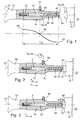
- FIG. 1 shows a device, designated overall by 10, for processing a workpiece 12, wherein a booster or converter 14, an ultrasonic sonotrode 16 and an anvil 18, which is fixed on a machine frame 20 only indicated, can be seen.
- the booster 14, the ultrasonic sonotrode 16, the workpiece 12 and the anvil 18 lie on an axis 22, in particular the longitudinal axis of the ultrasonic sonotrode 16, which also represents the machining direction.
- the ultrasonic sonotrode 16 has an end face 24 which represents the processing surface or welding surface 26. It points in the direction of the workpiece 12.
- the ultrasound sonotrode 16 has a recess designated overall by 28, which, for example, is designed as a bore 30 with a circular cross-section.
- the recess 28 is open on the front side 24, that is, it opens into the open, whereas on the opposite side a screw bolt 32 is screwed, to which in turn the booster 14 is attached.
- the recess 28 also extends in the direction of the axis 22 and is coaxial with this.
- the recess 28 is formed as a stepped bore and has in the region of the end face 24 a constriction 34.
- a punch 36 is slidably mounted in the recess 28 in the direction of the axis 22, wherein the punch 36 in the position shown in Figure 1 its rest position occupies.
- the stamp 36 receiving portion 38 of the recess 28 may have a circular or a polygonal cross-section.
- the punch 36 has a tapered end 40 which is dimensioned such that it can pass through the constriction 34 and emerge from the ultrasonic sonotrode 16, which is shown in FIG.
- the taper 34 serves as an end stop for the punch 36, which then, as shown in Figure 2, assumes its working position.
- a pressure chamber 42 On the opposite side of the punch 36 is a pressure chamber 42 which is provided with a port 44 which opens via a transverse bore 46 in the pressure chamber 42.
- the connection 44 is located in the vibration node 48 of the ultrasound sonotrode 16, wherein the latter has a respective antinode 50 on the end face 24 and on the opposite connection side for the booster 14. This can be clearly seen from the graph of a half wave of ⁇ / 2 shown below the cross section.
- a pressure medium for example a fluid, which may be a liquid or a gas, can be introduced into the pressure space 42 via the connection 44, as a result of which the punch 36 is moved out in the direction of the workpiece 12 and partially out of the ultrasound sonotrode 16. This is shown in FIG. Subsequently, the ultrasound sonotrode 16 is moved together with the booster 14 in the direction of the travel path S until the end 40 of the punch 36 rests against the workpiece 12. In the pressure chamber 42 there is a constant pressure, which is detected by means of a pressure sensor 52, which is also connected to the terminal 44. The workpiece 12 is held by the end 40 of the punch 36, wherein the punch 36 serves as a hold-down.
- a pressure medium for example a fluid, which may be a liquid or a gas
- the ultrasonic sonotrode 16 is further moved by the distance X in the direction of the workpiece 12 until the end face 24 abuts the surface of the workpiece 12, which is shown in FIG.
- the punch 36 is pushed back into the recess 28 against the holding force F I , since the feed force F S of the sonotrode 16 is greater.
- the workpiece 12 is retained due to the pressure P prevailing in the pressure chamber 42. This pressure P remains constant even when the punch 36 is pushed back into the recess 28, which is caused by the pressure sensor 52 is connected to a pressure regulator 54 which keeps the pressure P constant.
- the punch 36 thus serves for fixing the workpiece 12 and for damping ultrasonic vibrations in the region 56 on the workpiece 12.
- the punch 36 may also be formed as a punching tool, so that the workpiece 12 is punched by means of the punch 36 before or after the ultrasonic machining by the pressure P in the pressure chamber 42 is increased.
- the punch 36 is mounted without clearance in the recess 28 and in particular fluid-tight in this displaceable.
Landscapes
- Engineering & Computer Science (AREA)
- Mechanical Engineering (AREA)
- Life Sciences & Earth Sciences (AREA)
- Forests & Forestry (AREA)
- Physics & Mathematics (AREA)
- Fluid Mechanics (AREA)
- Perforating, Stamping-Out Or Severing By Means Other Than Cutting (AREA)
- Apparatuses For Generation Of Mechanical Vibrations (AREA)
Abstract
Description
- Die Erfindung betrifft eine Vorrichtung zum Bearbeiten von Werkstücken mittels Ultraschall, mit einer Ultraschallsonotrode und einem Amboss, wobei zwischen der Ultraschallsonotrode und dem Amboss ein Werkstück bearbeitet wird.
- Mit derartigen Ultraschallbearbeitungsvorrichtungen können Werkstücke gefügt oder miteinander verbunden werden. Mit derartigen Vorrichtungen können Werkstücke auch verschweißt oder getrennt, d.h. geschnitten werden. Ferner kann mit derartigen Vorrichtungen ein erstes Werkstückteil an einem zweiten Werkstückteil in einer bestimmten Lage fixiert werden. Bei der Bearbeitung von Werkstücken mittels Ultraschall besteht oftmals die Forderung, dass bestimmte Werkstückbereiche von der Ultraschalleinwirkung ausgenommen werden. Zum Beispiel müssen bestimmte einzelne Bauteile, die nicht miteinander verschweißt werden dürfen, fixiert, gehalten oder gedämpft werden. Außerdem sollten die Bauteile vor dem Bearbeiten sicher fixiert werden.
- Es ist bekannt, flexible Formteile vorzusehen, die in die Sonotrodenstirnfläche eingeklebt oder an dieser festgeklemmt werden. Damit soll eine Dämpfung bestimmter Bauteilbereiche während des Bearbeitungsvorganges möglich sein. Mit solchen Dämpfungselementen ist es aber nicht möglich, eine exakte Fixierung zu erzielen. Ebenso ist die Standzeit dieser Elemente relativ gering und die Abstimmung der Andruckkraft ist durch die hohe Federkonstante beziehungsweise der geringen Federlänge derartiger Dämpfungsglieder sehr problematisch.
- Zusätzlich zum Stand der Technik gemäß der
DE-A-25 08 175 , derDE-A-10 68 646 und derGB-A- 1 262 534 DE-U 92 12 560 federgelagerte, voreilende Niederhalter bekannt, die außerhalb der Sonotrode gelagert und geführt werden. Das Andrücken auf das zu bearbeitende Werkstück kann dabei außerhalb der Sonotrode erfolgen oder die Niederhalter sind, wie aus derDE-U-87 02 983 bekannt, ins Innere der Sonotrode geführt. Der Nachteil derartiger Ausführungen besteht darin, dass der Aufbau relativ aufwändig ist und dass er relativ viel Platz benötigt. Ferner sind auch diese Systeme mit mechanischen Federn vorgespannt. Somit ist der Anpressdruck nicht konstant und wegabhängig. - Bei anderen Ausführungsformen ist der mittels einer Feder vorgespannte Niederhalter im Schwingungsknoten der Ultraschallsonotrode gelagert. Als problematisch hat sich bei diesen Vorrichtungen herausgestellt, dass dennoch Schwingungen übertragen werden, da eine exakte Lagerung im Schwingungsknoten nur theoretisch möglich ist, da die gesamte Verschraubung beziehungsweise Befestigung eines solchen Niederhaltersystems sich über einen größeren Bereich erstreckt, der über den Schwingungsknoten hinausgeht. Die Folgen sind eine Erwärmung, Vibrationen und eine Erhöhung der Verlustleistung des Gesamtsystems. Dies resultiert in einer verkürzten Lebensdauer und in einer eingeschränkten Zuverlässigkeit derartiger Systeme.
- Der Erfindung liegt daher die Aufgabe zugrunde, eine Vorrichtung der eingangs genannten Art derart weiterzubilden, dass die Ultraschallsonotrode bei einfachem und kompaktem Aufbau mit einem Niederhalter oder Dämpfungselement versehen werden kann.
- Diese Aufgabe wird bei einer Vorrichtung der eingangs genannten Art erfindungsgemäß dadurch gelöst, dass die Ultraschallsonotrode in Achslängsrichtung und in Richtung auf das Werkstück und/oder den Amboss eine randoffene Ausnehmung aufweist, dass in der Ausnehmung ein Stempel angeordnet ist und dass der Stempel zwischen einer in die Ultraschallsonotrode eingefahrenen Ruhelage und einer teilweise aus der Sonotrode herausragenden Arbeitlage verfahrbar ist.
- Die erfindungsgemäße Ausgestaltung sieht demnach vor, dass der Niederhalter beziehungsweise das Dämpfungselement als Stempel, Bolzen oder Stößel ausgebildet ist und dieser Stempel in die Ultraschallsonotrode integriert ist, wobei der Stempel eine Ruhelage und eine Arbeitslage einnehmen kann, indem er in der Ausnehmung verlagert wird. Die Funktion des Stempels kann also aus- und eingeschaltet werden. Bei einer Variante kann der Stempel auch innerhalb der Ultraschallsonotrode fixiert werden, so dass er einen Teil der schwingenden Ultraschallsonotrode bildet, und zur Bearbeitung des Werkstücks beiträgt.
- Bei einer Weiterbildung ist vorgesehen, dass die Ausnehmung eine Bohrung, insbesondere eine Stufenbohrung, mit kreisrundem oder polygonalem Querschnitt ist. Dabei kann der Stempel auf einfache Weise als Zylinderstift ausgebildet sein. Soll der Stempel eine bestimmte Ausrichtung beibehalten, wird dieser mit einem polygonalen Querschnitt versehen, so dass er lediglich in einer Dimension, nämlich in seiner Längsrichtung verlagert werden kann. Besitzt der Zylinderstift eine Schulter, dann kann der Verfahrweg des Stempels begrenzt werden, so dass er nur über einen bestimmten Betrag oder Zustellweg aus der Ultraschallsonotrode ausgefahren werden kann.
- Optimale Schweißergebnisse werden dann erzielt, wenn der Stempel spielfrei oder nahezu spielfrei in der Ausnehmung geführt ist. Zusätzlich liegt der Stempel fluiddicht, insbesondere pneumatisch dicht in der Ausnehmung und kann mittels eines Fluides nach Art eines Kolbens verschoben werden.
- Bei einem Ausführungsbeispiel ist vorgesehen, dass die Ausnehmung einen Druckraum bildet und einen Anschluss für ein Arbeitsfluid aufweist. Mittels des Arbeitsfluides wird der Stempel in der Ausnehmung bewegt und es können Kräfte auf den Stempel ausgeübt werden. Dabei kann die Kraft auf den Stempel und somit die Kraft des Niederhalters beziehungsweise des Dämpfungselements exakt durch den Druck des Fluides eingestellt werden.
- In bevorzugter Weise befindet sich der Anschluss für das Arbeitsfluid in einem Schwingungsknoten. Selbstverständlich ist auch eine andere Position möglich, sofern der Anschluss über geeignete Maßnahmen, insbesondere elastische Verbindungen, schwingungsentkoppelt ist.
- Dabei führt der Anschluss zu einer Fluidquelle und/oder einem Drucksensor, insbesondere mit einem Druckregler. Auf diese Weise kann nicht nur der Stempel von der Ruhelage in die Arbeitslage und zurück verfahren, sondern auch die gewünschte Haltekraft aufgebracht und sogar konstant gehalten werden, und zwar unabhängig von der Position des Stempels in der Ausnehmung.
- Bei einem besonders bevorzugten Ausführungsbeispiel ist die Haltekraft so gewählt, dass sie kleiner ist, als die Zustellkraft der Ultraschallsonotrode. Wird die Ultraschallsonotrode auf das Werkstück aufgesetzt, liegt zunächst der Stempel am Werkstück an und dient als Niederhalter für das Werkstück und wird dann mit weiterer Zustellung der Ultraschallsonotrode in Richtung des Werkstücks in die Ultraschallsonotrode eingedrückt. Dabei bleibt die Haltekraft konstant. Sobald die Sonotrode am Werkstück anliegt, kann die Haltekraft auf Null reduziert beziehungsweise der Stempel vollständig in die Sonotrode eingezogen werden.
- Es besteht aber auch die Möglichkeit, dass während oder nach der Bearbeitung des Werkstücks mittels der Ultraschallsonotrode der Stempel wieder ausgefahren wird und dabei einen Stanzvorgang ausführt. Der Stempel ist dann nicht nur ein Niederhalter, sondern auch gleichzeitig ein Stanzwerkzeug.
- Bevorzugt kann die Kontaktfläche des Stempels auch strukturiert sein, so dass das Werkstück mit Sicherheit gehalten wird. Für den Stempel können beliebige Materialien gewählt werden, wie Metall, Kunststoff oder Keramik sowie Kombinationen hiervon.
- Weitere Vorteile, Merkmale und Einzelheiten der Erfindung ergeben sich aus der nachfolgenden Beschreibung, in der unter Bezugnahme auf die Zeichnung ein besonders bevorzugtes Ausführungsbeispiel im Einzelnen beschrieben ist. Dabei können die in der Zeichnung dargestellten sowie in den Ansprüchen und in der Beschreibung erwähnten Merkmale jeweils einzeln für sich oder in beliebiger Kombination erfindungswesentlich sein.
- In der Zeichnung zeigen:
- Figur 1
- einen Längsschnitt durch die erfindungsgemäße Vorrichtung vor dem Aufsetzen auf ein Werkstück;
- Figur 2
- die Vorrichtung gemäß Figur 1 beim Aufsetzen auf das Werkstück; und
- Figur 3
- die Vorrichtung gemäß Figur 1 beim Bearbeiten des Werkstücks.
- Die Figur 1 zeigt eine insgesamt mit 10 bezeichnete Vorrichtung zum Bearbeiten eines Werkstücks 12, wobei ein Booster oder Konverter 14, eine Ultraschallsonotrode 16 und ein Amboss 18, der an einem nur angedeuteten Maschinengestell 20 fixiert ist, erkennbar sind. Der Booster 14, die Ultraschallsonotrode 16, das Werkstück 12 und der Amboss 18 liegen auf einer Achse 22, insbesondere der Längsachse der Ultraschallsonotrode 16, die auch die Bearbeitungsrichtung darstellt. Die Ultraschallsonotrode 16 besitzt eine Stirnseite 24, die die Bearbeitungsfläche oder Schweißfläche 26 darstellt. Sie zeigt in Richtung auf das Werkstück 12.
- Die Ultraschallsonotrode 16 besitzt eine insgesamt mit 28 bezeichnete Ausnehmung, die zum Beispiel als Bohrung 30 mit einem kreisrunden Querschnitt ausgeführt ist. Die Ausnehmung 28 ist an der Stirnseite 24 randoffen, das heißt sie mündet ins Freie, wohingegen auf der gegenüberliegenden Seite ein Schraubbolzen 32 eingeschraubt ist, an welchem wiederum der Booster 14 befestigt ist.
- Die Ausnehmung 28 erstreckt sich ebenfalls in Richtung der Achse 22 und liegt koaxial zu dieser. Außerdem ist die Ausnehmung 28 als Stufenbohrung ausgebildet und besitzt im Bereich der Stirnseite 24 eine Einschnürung 34. Ferner ist in der Ausnehmung 28 ein Stempel 36 in Richtung der Achse 22 verschieblich gelagert, wobei der Stempel 36 in der in der Figur 1 dargestellten Stellung seine Ruhelage einnimmt. Dabei kann der den Stempel 36 aufnehmende Bereich 38 der Ausnehmung 28 einen kreisrunden oder einen polygonen Querschnitt aufweisen. Weiterhin ist erkennbar, dass der Stempel 36 ein verjüngtes Ende 40 aufweist, welches so bemessen ist, dass es die Einschnürung 34 durchgreifen und aus der Ultraschallsonotrode 16 heraustreten kann, was in der Figur 2 dargestellt ist. Dabei dient die Verjüngung 34 als Endanschlag für den Stempel 36, der dann, wie in der Figur 2 dargestellt, seine Arbeitsposition einnimmt.
- Auf der gegenüberliegenden Seite des Stempels 36 befindet sich ein Druckraum 42, der mit einem Anschluss 44 versehen ist, der über eine Querbohrung 46 in den Druckraum 42 mündet. Der Anschluss 44 liegt im Schwingungsknoten 48 der Ultraschallsonotrode 16, wobei diese an der Stirnseite 24 sowie an der gegenüberliegenden Anschlussseite für den Booster 14 jeweils einen Schwingungsbauch 50 aufweist. Dies ist deutlich aus dem unterhalb des Querschnitts gezeigten Schaubilds einer Halbwelle von λ/2 erkennbar.
- Über den Anschluss 44 kann ein Druckmedium, zum Beispiel ein Fluid, was eine Flüssigkeit oder ein Gas sein kann, in den Druckraum 42 eingeleitet werden, wodurch der Stempel 36 in Richtung auf das Werkstück 12 und teilweise aus der Ultraschallsonotrode 16 herausbewegt wird. Dies ist in der Figur 2 dargestellt. Anschließend wird die Ultraschallsonotrode 16 zusammen mit dem Booster 14 in Richtung des Verfahrweges S bewegt, bis das Ende 40 des Stempels 36 am Werkstück 12 anliegt. Im Druckraum 42 herrscht ein konstanter Druck, der mittels eines Drucksensors 52, der ebenfalls am Anschluss 44 angeschlossen ist, erfasst wird. Das Werkstück 12 wird vom Ende 40 des Stempels 36 festgehalten, wobei der Stempel 36 als Niederhalter dient.
- Sodann wird die Ultraschallsonotrode 16 weiter um die Wegstrecke X in Richtung auf das Werkstück 12 bewegt, bis die Stirnseite 24 an der Oberfläche des Werkstücks 12 anliegt, was in der Figur 3 dargestellt ist. Dabei wird der Stempel 36 in die Ausnehmung 28 entgegen der Haltekraft FI zurückgeschoben, da die Zustellkraft FS der Sonotrode 16 größer ist. Das Werkstück 12 wird jedoch aufgrund des im Druckraum 42 herrschenden Drucks P festgehalten. Dieser Druck P bleibt konstant, auch wenn der Stempel 36 in die Ausnehmung 28 zurückgeschoben wird, was dadurch bewirkt wird, dass der Drucksensor 52 an einen Druckregler 54 angeschlossen ist, der den Druck P konstant hält.
- Sobald die Stirnseite 24 auf dem Werkstück 12 aufsitzt, wird dieses bearbeitet. Der vom Ende 40 des Stempels 36 abgedeckte Bereich des Werkstücks 12 wird nicht bearbeitet, da der Stempel 36 den Ultraschallschwingungen der Ultraschallsonotrode 16 nicht folgt. Dieser Bereich ist am Werkstück 12 mit 56 bezeichnet.
- Der Stempel 36 dient also zur Fixierung des Werkstücks 12 sowie zur Dämpfung von Ultraschallschwingungen im Bereich 56 auf dem Werkstück 12. Dabei kann der Stempel 36 auch als Stanzwerkzeug ausgebildet sein, so dass vor oder nach der Ultraschallbearbeitung das Werkstück 12 mittels des Stempels 36 gestanzt wird, indem im Druckraum 42 der Druck P erhöht wird. Der Stempel 36 ist spielfrei in der Ausnehmung 28 und insbesondere fluiddicht in dieser verschieblich gelagert.
Claims (13)
- Vorrichtung (10) zum Bearbeiten von Werkstücken (12) mittels Ultraschall, mit einer Ultraschallsonotrode (16) und einem Amboss (18), wobei zwischen der Ultraschallsonotrode (16) und dem Amboss (18) ein Werkstück (12) bearbeitet wird, dadurch gekennzeichnet, dass die Ultraschallsonotrode (16) in Achsrichtung (22) und in Richtung auf das Werkstück (12) und/oder den Amboss (18) eine randoffene Ausnehmung (28) aufweist, dass in der Ausnehmung (28) ein Stempel (36) angeordnet ist und dass der Stempel (36) zwischen einer in die Ultraschallsonotrode (16) eingefahrenen Ruhelage und einer teilweise aus der Ultraschallsonotrode (16) herausragenden Arbeitlage verfahrbar ist.
- Vorrichtung nach Anspruch 1, dadurch gekennzeichnet, dass die Ausnehmung (28) eine Bohrung, insbesondere eine Stufenbohrung ist.
- Vorrichtung nach Anspruch 1 oder 2, dadurch gekennzeichnet, dass der Stempel (36) einen den Verschiebeweg begrenzenden Anschlag aufweist.
- Vorrichtung nach einem der vorhergehenden Ansprüche, dadurch gekennzeichnet, dass die Ausnehmung (28) einen kreisrunden oder einen polygonalen Querschnitt aufweist.
- Vorrichtung nach einem der vorhergehenden Ansprüche, dadurch gekennzeichnet, dass der Stempel (36) spielfrei oder nahezu spielfrei in der Ausnehmung (28) geführt ist.
- Vorrichtung nach einem der vorhergehenden Ansprüche, dadurch gekennzeichnet, dass der Stempel (36) fluiddicht, insbesondere pneumatisch dicht, in der Ausnehmung (28) gelagert ist.
- Vorrichtung nach einem der vorhergehenden Ansprüche, dadurch gekennzeichnet, dass die Ausnehmung (28) einen Druckraum (42) bildet und einen Anschluss (44) für ein Fluid aufweist.
- Vorrichtung nach Anspruch 7, dadurch gekennzeichnet, dass der Anschluss (44) in einem Schwingungsknoten (48) liegt.
- Vorrichtung nach Anspruch 7 oder 8, dadurch gekennzeichnet, dass der Anschluss (44) zu einer Fluidquelle und/oder einem Drucksensor (52) führt.
- Vorrichtung nach Anspruch 9, dadurch gekennzeichnet, dass der Drucksensor (52) mit einem Druckregler (54) verbunden ist.
- Vorrichtung nach einem der vorhergehenden Ansprüche, dadurch gekennzeichnet, dass die Zustellkraft (Fs) der Ultraschallsonotrode (16) größer ist als die Kraft (FI), mit der der Stempel (36) aus der Ausnehmung (28) gedrückt wird.
- Vorrichtung nach einem der vorhergehenden Ansprüche, dadurch gekennzeichnet, dass die das Werkstück (12) kontaktierende Fläche des Stempels (36) strukturiert ist.
- Vorrichtung nach einem der vorhergehenden Ansprüche, dadurch gekennzeichnet, dass der Stempel (36) als Stanzwerkzeug ausgebildet ist.
Applications Claiming Priority (1)
| Application Number | Priority Date | Filing Date | Title |
|---|---|---|---|
| DE102006020418A DE102006020418A1 (de) | 2006-04-26 | 2006-04-26 | Vorrichtung zum Bearbeiten von Werkstücken mittels Ultraschall |
Publications (3)
| Publication Number | Publication Date |
|---|---|
| EP1849583A2 true EP1849583A2 (de) | 2007-10-31 |
| EP1849583A3 EP1849583A3 (de) | 2009-08-05 |
| EP1849583B1 EP1849583B1 (de) | 2014-08-06 |
Family
ID=38222297
Family Applications (1)
| Application Number | Title | Priority Date | Filing Date |
|---|---|---|---|
| EP07001813.0A Active EP1849583B1 (de) | 2006-04-26 | 2007-01-27 | Vorrichtung zum Bearbeiten von Werkstücken mittels Ultraschall |
Country Status (4)
| Country | Link |
|---|---|
| US (1) | US7959054B2 (de) |
| EP (1) | EP1849583B1 (de) |
| DE (1) | DE102006020418A1 (de) |
| HK (1) | HK1105393A1 (de) |
Cited By (5)
| Publication number | Priority date | Publication date | Assignee | Title |
|---|---|---|---|---|
| CN101823179A (zh) * | 2009-03-05 | 2010-09-08 | 必能信超声公司 | 零件感测焊头 |
| EP2873512A1 (de) * | 2013-11-15 | 2015-05-20 | MS Spaichingen GmbH | Verfahren und Vorrichtung zum Stanzen und Verbinden von Kunststoffteilen |
| WO2016023823A1 (de) * | 2014-08-14 | 2016-02-18 | Herrmann Ultraschalltechnik Gmbh & Co. Kg | Schwingungselement mit entkoppeltem bauteil |
| CN105992656A (zh) * | 2014-02-13 | 2016-10-05 | 海尔曼超声波技术两合有限公司 | 具有加厚部的超声焊极 |
| WO2020126836A3 (de) * | 2018-12-19 | 2020-08-13 | Herrmann Ultraschalltechnik Gmbh & Co. Kg | Ultraschallschweissanlage mit formschlüssiger verbindung |
Families Citing this family (12)
| Publication number | Priority date | Publication date | Assignee | Title |
|---|---|---|---|---|
| DE102011084157B3 (de) * | 2011-10-07 | 2013-01-03 | Continental Automotive Gmbh | Ultraschallschweißvorrichtung und Verfahren zum Verschweißen von Werkstücken |
| US9854833B2 (en) | 2012-02-16 | 2018-01-02 | R. J. Reynolds Tobacco Company | Apparatus and associated method for forming a filter component of a smoking article |
| DE102013202766A1 (de) | 2013-02-20 | 2014-08-21 | Ms Spaichingen Gmbh | Rundsonotrode |
| US9931684B2 (en) | 2014-04-18 | 2018-04-03 | Honda Motor Co., Ltd. | Forming die and method of using the same |
| EP3037235B1 (de) * | 2014-12-23 | 2017-09-27 | Ultrasion, Sl | Vorrichtung und Verfahren für geschmolzene Kunststoffmaterialzufuhr zu einem Formhohlraum |
| DE102015106265A1 (de) * | 2015-02-06 | 2016-08-11 | Auto-Kabel Management Gmbh | Ultraschallschweißvorrichtung sowie Verfahren zum Ultraschallschweißen |
| DE102016107958A1 (de) | 2016-04-28 | 2017-11-02 | Herrmann Ultraschalltechnik Gmbh & Co. Kg | Stanz-Siegeleinheit und Ultraschallbearbeitungsvorrichtung mit einer solchen |
| JP6596707B2 (ja) * | 2016-07-25 | 2019-10-30 | 信越ポリマー株式会社 | キャリアテープの製造方法 |
| DE102017127826A1 (de) * | 2017-11-24 | 2019-05-29 | Herrmann Ultraschalltechnik Gmbh & Co. Kg | Ultraschallschwingeinheit mit Dämpfung |
| DE102019128745A1 (de) * | 2019-10-24 | 2021-04-29 | Bayerische Motoren Werke Aktiengesellschaft | Ultraschallschweißvorrichtung und Verfahren zum Ultraschallverschweißen von mindestens zwei Bauteilen |
| DE102019134778A1 (de) * | 2019-12-17 | 2021-06-17 | Auto-Kabel Management Gmbh | Ultraschallschweißvorrichtung sowie Verfahren zum Ultraschallschweißen |
| DE102020115036A1 (de) * | 2020-06-05 | 2021-12-09 | Syntegon Technology Gmbh | Schweißvorrichtung sowie Verfahren zum Schweißen eines Auslasselements an ein Verpackungsmaterial |
Citations (8)
| Publication number | Priority date | Publication date | Assignee | Title |
|---|---|---|---|---|
| DE1068646B (de) | 1959-11-12 | HAUHINCO Maschinenfabrik G. Hausherr Jochums ix Co., Essen | An einem Abbauhammer angeordnete Vorrichtung zum Verspritzen von Druckwasser auf die Arbeitsstelle | |
| GB1262534A (en) | 1968-11-20 | 1972-02-02 | Branson Instr | Sonic or ultrasonic horns for use in piezoelectric and other transducers |
| US3697357A (en) | 1970-07-17 | 1972-10-10 | Branson Instr | Ultrasonic sealing apparatus |
| DE2508175A1 (de) | 1974-03-19 | 1975-10-09 | Cavitron Corp | Ultraschallvorrichtung und verfahren zur verwendung eines stroemenden mediums in einer ultraschallvorrichtung und in einem arbeitsbereich um das vorstehende werkzeug der vorrichtung herum |
| DE8702983U1 (de) | 1987-02-26 | 1988-06-23 | Siemens Ag, 1000 Berlin Und 8000 Muenchen, De | |
| DE9212560U1 (de) | 1992-09-17 | 1993-03-18 | Branson Ultraschall Niederlassung Der Emerson Technologies Gmbh & Co, 6057 Dietzenbach, De | |
| GB2320906A (en) | 1997-01-03 | 1998-07-08 | Staples Group Plc | Ultrasonic cutting machine |
| EP1468794A1 (de) | 2003-04-15 | 2004-10-20 | Telsonic Holding AG | Vorrichtung und Verfahren zum Anbringen von Öffnungen in Formteilen mit einer Ultraschallquelle |
Family Cites Families (13)
| Publication number | Priority date | Publication date | Assignee | Title |
|---|---|---|---|---|
| US3038358A (en) * | 1957-12-30 | 1962-06-12 | Aeroprojects Inc | Ultrasonic devices |
| US3464102A (en) * | 1967-03-10 | 1969-09-02 | Branson Instr | Solid acoustic horn with suction means |
| NL6802279A (de) * | 1968-02-16 | 1969-08-19 | ||
| US3526554A (en) * | 1968-10-31 | 1970-09-01 | Branson Instr | Method for producing a fillet type weld on thermoplastic material using ultrasonic energy |
| DE3603627A1 (de) * | 1985-10-23 | 1987-04-23 | Kln Ultraschall Gmbh | Verfahren und vorrichtung zum einarbeiten von oeffnungen in behaelter aus thermoplastischen kunststoffen |
| JPH0248153A (ja) * | 1988-08-04 | 1990-02-16 | Mitsubishi Electric Corp | 超音波振動体の支持装置 |
| FR2643303B3 (fr) * | 1989-02-21 | 1991-10-11 | Mecasonic Sa | Procede de decoupage en secteurs de produits circulaires, notamment alimentaires |
| US5427301A (en) * | 1994-05-06 | 1995-06-27 | Ford Motor Company | Ultrasonic flip chip process and apparatus |
| GB9805176D0 (en) * | 1998-03-12 | 1998-05-06 | Rosslyn Precision Ltd | Ultrasonic seam bonding method and apparatus |
| US6309490B1 (en) * | 2000-05-10 | 2001-10-30 | Branson Ultrasonics Corporation | Air actuated ultrasonic tool |
| KR100773170B1 (ko) * | 2000-09-12 | 2007-11-02 | 언액시스 인터내셔널 트레이딩 엘티디 | 반도체 칩을 장착하는 방법 및 장치 |
| US6616031B2 (en) * | 2001-07-17 | 2003-09-09 | Asm Assembly Automation Limited | Apparatus and method for bond force control |
| US7748590B2 (en) * | 2005-05-16 | 2010-07-06 | Ford Global Technologies, Llc | Ultrasonic welding apparatus |
-
2006
- 2006-04-26 DE DE102006020418A patent/DE102006020418A1/de not_active Withdrawn
-
2007
- 2007-01-27 EP EP07001813.0A patent/EP1849583B1/de active Active
- 2007-03-19 US US11/723,214 patent/US7959054B2/en active Active
- 2007-12-19 HK HK07113901.4A patent/HK1105393A1/xx unknown
Patent Citations (8)
| Publication number | Priority date | Publication date | Assignee | Title |
|---|---|---|---|---|
| DE1068646B (de) | 1959-11-12 | HAUHINCO Maschinenfabrik G. Hausherr Jochums ix Co., Essen | An einem Abbauhammer angeordnete Vorrichtung zum Verspritzen von Druckwasser auf die Arbeitsstelle | |
| GB1262534A (en) | 1968-11-20 | 1972-02-02 | Branson Instr | Sonic or ultrasonic horns for use in piezoelectric and other transducers |
| US3697357A (en) | 1970-07-17 | 1972-10-10 | Branson Instr | Ultrasonic sealing apparatus |
| DE2508175A1 (de) | 1974-03-19 | 1975-10-09 | Cavitron Corp | Ultraschallvorrichtung und verfahren zur verwendung eines stroemenden mediums in einer ultraschallvorrichtung und in einem arbeitsbereich um das vorstehende werkzeug der vorrichtung herum |
| DE8702983U1 (de) | 1987-02-26 | 1988-06-23 | Siemens Ag, 1000 Berlin Und 8000 Muenchen, De | |
| DE9212560U1 (de) | 1992-09-17 | 1993-03-18 | Branson Ultraschall Niederlassung Der Emerson Technologies Gmbh & Co, 6057 Dietzenbach, De | |
| GB2320906A (en) | 1997-01-03 | 1998-07-08 | Staples Group Plc | Ultrasonic cutting machine |
| EP1468794A1 (de) | 2003-04-15 | 2004-10-20 | Telsonic Holding AG | Vorrichtung und Verfahren zum Anbringen von Öffnungen in Formteilen mit einer Ultraschallquelle |
Cited By (8)
| Publication number | Priority date | Publication date | Assignee | Title |
|---|---|---|---|---|
| CN101823179A (zh) * | 2009-03-05 | 2010-09-08 | 必能信超声公司 | 零件感测焊头 |
| EP2873512A1 (de) * | 2013-11-15 | 2015-05-20 | MS Spaichingen GmbH | Verfahren und Vorrichtung zum Stanzen und Verbinden von Kunststoffteilen |
| US9630361B2 (en) | 2013-11-15 | 2017-04-25 | Ms Ultraschall Technologie Gmbh | Method and apparatus for punching and connecting plastic parts |
| CN105992656A (zh) * | 2014-02-13 | 2016-10-05 | 海尔曼超声波技术两合有限公司 | 具有加厚部的超声焊极 |
| US9908286B2 (en) | 2014-02-13 | 2018-03-06 | Herrmann Ultraschalltechnik Gmbh & Co. Kg | Sonotrode with thickened portion |
| WO2016023823A1 (de) * | 2014-08-14 | 2016-02-18 | Herrmann Ultraschalltechnik Gmbh & Co. Kg | Schwingungselement mit entkoppeltem bauteil |
| US10974278B2 (en) | 2014-08-14 | 2021-04-13 | Herrmann Ultraschalltechnik Gmbh & Co. Kg | Vibration element with decoupled component |
| WO2020126836A3 (de) * | 2018-12-19 | 2020-08-13 | Herrmann Ultraschalltechnik Gmbh & Co. Kg | Ultraschallschweissanlage mit formschlüssiger verbindung |
Also Published As
| Publication number | Publication date |
|---|---|
| US20070251978A1 (en) | 2007-11-01 |
| US7959054B2 (en) | 2011-06-14 |
| HK1105393A1 (en) | 2008-02-15 |
| EP1849583A3 (de) | 2009-08-05 |
| DE102006020418A1 (de) | 2007-10-31 |
| EP1849583B1 (de) | 2014-08-06 |
Similar Documents
| Publication | Publication Date | Title |
|---|---|---|
| EP1849583B1 (de) | Vorrichtung zum Bearbeiten von Werkstücken mittels Ultraschall | |
| DE69317303T3 (de) | Selbststanzende nieten | |
| EP1910029B1 (de) | Spannvorrichtung | |
| DE2718766C3 (de) | Stempel-Abstreifer-Anordnung | |
| DE2924707C2 (de) | ||
| AT507131A2 (de) | Spanneinrichtung | |
| EP3505270B1 (de) | Setzeinheit für eine stanznietvorrichtung, stanznietvorrichtung und verfahren zum herstellen einer solchen | |
| EP3362212A1 (de) | Spanabhebendes werkzeug | |
| DE102010008187A1 (de) | Werkzeug zur spanenden Materialbearbeitung sowie Verfahren zum Ausrichten von Schneideinsätzen in einem solchen Werkzeug | |
| DE19917146A1 (de) | Nullpunktspannsystem | |
| DE102005034476A1 (de) | Hydraulische Spannvorrichtung zum radialen und axialen Spannen | |
| EP3569354B1 (de) | Vorrichtung zur fixierung von werkstücken und bearbeitungsanlage. | |
| DE102006053223B3 (de) | Loch- und Durchzugsstempel | |
| EP0362753B1 (de) | Einspannvorrichtung | |
| EP3484659B1 (de) | Spannvorrichtung | |
| DE202008003866U1 (de) | Zerspanungswerkzeug | |
| EP2177296B1 (de) | Dehnspanneinrichtung | |
| EP3158209B1 (de) | Verfahren zum verpressen einer kugel mit einem ersten bauteil | |
| DE19512594C2 (de) | Transportable Lochstanze mit Andrückkolben | |
| DE102016202243A1 (de) | Stanznietvorrichtung und stanznietverfahren zum stanznieten mit ultraschall | |
| DE102013010493A1 (de) | Vorrichtung und Verfahren zur automatisierten Ausbildung einer Fügeverbindung | |
| DE102012017289A1 (de) | Einprägeelement insbesondere für das Widerstandsschweißen | |
| DE102019135273B4 (de) | Verfahren zum Detektieren von Verbindungselementen, insbesondere Fließlochschrauben, bei mechanischen Füge- und Umformprozessen in welchem ein Fehlerfall des Prozesses erkannt wurde | |
| EP3095552B1 (de) | Kalibrierwerkzeug | |
| DE102008006262A1 (de) | Zerspanungswerkzeug |
Legal Events
| Date | Code | Title | Description |
|---|---|---|---|
| PUAI | Public reference made under article 153(3) epc to a published international application that has entered the european phase |
Free format text: ORIGINAL CODE: 0009012 |
|
| AK | Designated contracting states |
Kind code of ref document: A2 Designated state(s): AT BE BG CH CY CZ DE DK EE ES FI FR GB GR HU IE IS IT LI LT LU LV MC NL PL PT RO SE SI SK TR |
|
| AX | Request for extension of the european patent |
Extension state: AL BA HR MK YU |
|
| REG | Reference to a national code |
Ref country code: HK Ref legal event code: DE Ref document number: 1105393 Country of ref document: HK |
|
| PUAL | Search report despatched |
Free format text: ORIGINAL CODE: 0009013 |
|
| AK | Designated contracting states |
Kind code of ref document: A3 Designated state(s): AT BE BG CH CY CZ DE DK EE ES FI FR GB GR HU IE IS IT LI LT LU LV MC NL PL PT RO SE SI SK TR |
|
| AX | Request for extension of the european patent |
Extension state: AL BA HR MK RS |
|
| 17P | Request for examination filed |
Effective date: 20091105 |
|
| 17Q | First examination report despatched |
Effective date: 20091130 |
|
| AKX | Designation fees paid |
Designated state(s): CH DE FR GB IT LI |
|
| GRAP | Despatch of communication of intention to grant a patent |
Free format text: ORIGINAL CODE: EPIDOSNIGR1 |
|
| INTG | Intention to grant announced |
Effective date: 20140204 |
|
| GRAP | Despatch of communication of intention to grant a patent |
Free format text: ORIGINAL CODE: EPIDOSNIGR1 |
|
| INTG | Intention to grant announced |
Effective date: 20140326 |
|
| GRAS | Grant fee paid |
Free format text: ORIGINAL CODE: EPIDOSNIGR3 |
|
| GRAA | (expected) grant |
Free format text: ORIGINAL CODE: 0009210 |
|
| AK | Designated contracting states |
Kind code of ref document: B1 Designated state(s): CH DE FR GB IT LI |
|
| REG | Reference to a national code |
Ref country code: GB Ref legal event code: FG4D Free format text: NOT ENGLISH |
|
| REG | Reference to a national code |
Ref country code: CH Ref legal event code: EP Ref country code: CH Ref legal event code: NV Representative=s name: DREISS PATENTANWAELTE PARTG MBB, DE |
|
| REG | Reference to a national code |
Ref country code: DE Ref legal event code: R096 Ref document number: 502007013332 Country of ref document: DE Effective date: 20140918 |
|
| REG | Reference to a national code |
Ref country code: CH Ref legal event code: PCAR Free format text: NEW ADDRESS: FRIEDERICHSTR. 6, 70174 STUTTGART (DE) |
|
| REG | Reference to a national code |
Ref country code: CH Ref legal event code: PCAR Free format text: NEW ADDRESS: FRIEDRICHSTR. 6, 70174 STUTTGART (DE) |
|
| REG | Reference to a national code |
Ref country code: DE Ref legal event code: R097 Ref document number: 502007013332 Country of ref document: DE |
|
| PLBE | No opposition filed within time limit |
Free format text: ORIGINAL CODE: 0009261 |
|
| REG | Reference to a national code |
Ref country code: HK Ref legal event code: GR Ref document number: 1105393 Country of ref document: HK |
|
| STAA | Information on the status of an ep patent application or granted ep patent |
Free format text: STATUS: NO OPPOSITION FILED WITHIN TIME LIMIT |
|
| 26N | No opposition filed |
Effective date: 20150507 |
|
| REG | Reference to a national code |
Ref country code: FR Ref legal event code: PLFP Year of fee payment: 10 |
|
| REG | Reference to a national code |
Ref country code: FR Ref legal event code: PLFP Year of fee payment: 11 |
|
| REG | Reference to a national code |
Ref country code: FR Ref legal event code: PLFP Year of fee payment: 12 |
|
| PGFP | Annual fee paid to national office [announced via postgrant information from national office to epo] |
Ref country code: FR Payment date: 20230123 Year of fee payment: 17 |
|
| PGFP | Annual fee paid to national office [announced via postgrant information from national office to epo] |
Ref country code: IT Payment date: 20230131 Year of fee payment: 17 Ref country code: GB Payment date: 20230117 Year of fee payment: 17 |
|
| PGFP | Annual fee paid to national office [announced via postgrant information from national office to epo] |
Ref country code: DE Payment date: 20240318 Year of fee payment: 18 Ref country code: CH Payment date: 20240202 Year of fee payment: 18 |