EP1847227B1 - Elektrisches Marknagelsystem - Google Patents
Elektrisches Marknagelsystem Download PDFInfo
- Publication number
- EP1847227B1 EP1847227B1 EP07006869A EP07006869A EP1847227B1 EP 1847227 B1 EP1847227 B1 EP 1847227B1 EP 07006869 A EP07006869 A EP 07006869A EP 07006869 A EP07006869 A EP 07006869A EP 1847227 B1 EP1847227 B1 EP 1847227B1
- Authority
- EP
- European Patent Office
- Prior art keywords
- set forth
- end cap
- intramedullary nail
- nail
- nail system
- Prior art date
- Legal status (The legal status is an assumption and is not a legal conclusion. Google has not performed a legal analysis and makes no representation as to the accuracy of the status listed.)
- Active
Links
- 230000006835 compression Effects 0.000 claims description 14
- 238000007906 compression Methods 0.000 claims description 14
- 238000000576 coating method Methods 0.000 claims description 13
- 239000011248 coating agent Substances 0.000 claims description 12
- 230000000149 penetrating effect Effects 0.000 claims description 7
- 239000012799 electrically-conductive coating Substances 0.000 claims description 6
- 229910052709 silver Inorganic materials 0.000 claims description 6
- 239000004332 silver Substances 0.000 claims description 6
- 208000034309 Bacterial disease carrier Diseases 0.000 claims 1
- 239000011229 interlayer Substances 0.000 claims 1
- 239000010410 layer Substances 0.000 claims 1
- 210000000988 bone and bone Anatomy 0.000 description 17
- 210000001519 tissue Anatomy 0.000 description 16
- 206010017076 Fracture Diseases 0.000 description 8
- 230000005684 electric field Effects 0.000 description 8
- 230000035876 healing Effects 0.000 description 8
- 208000010392 Bone Fractures Diseases 0.000 description 7
- 239000007943 implant Substances 0.000 description 7
- 238000009413 insulation Methods 0.000 description 7
- 230000000694 effects Effects 0.000 description 6
- 230000011164 ossification Effects 0.000 description 6
- BQCADISMDOOEFD-UHFFFAOYSA-N Silver Chemical compound [Ag] BQCADISMDOOEFD-UHFFFAOYSA-N 0.000 description 5
- 230000001965 increasing effect Effects 0.000 description 5
- 239000000696 magnetic material Substances 0.000 description 5
- 238000000034 method Methods 0.000 description 5
- 230000000844 anti-bacterial effect Effects 0.000 description 4
- 239000012634 fragment Substances 0.000 description 4
- 238000002513 implantation Methods 0.000 description 4
- 229910052751 metal Inorganic materials 0.000 description 4
- 239000002184 metal Substances 0.000 description 4
- 230000006641 stabilisation Effects 0.000 description 4
- 238000011105 stabilization Methods 0.000 description 4
- 241000894006 Bacteria Species 0.000 description 3
- 208000003076 Osteolysis Diseases 0.000 description 3
- 230000008468 bone growth Effects 0.000 description 3
- 230000001939 inductive effect Effects 0.000 description 3
- 208000015181 infectious disease Diseases 0.000 description 3
- 208000029791 lytic metastatic bone lesion Diseases 0.000 description 3
- 239000000463 material Substances 0.000 description 3
- 230000001097 osteosynthetic effect Effects 0.000 description 3
- 239000002245 particle Substances 0.000 description 3
- 239000004033 plastic Substances 0.000 description 3
- 229920003023 plastic Polymers 0.000 description 3
- 239000004698 Polyethylene Substances 0.000 description 2
- 241000191967 Staphylococcus aureus Species 0.000 description 2
- 229910001069 Ti alloy Inorganic materials 0.000 description 2
- 230000004071 biological effect Effects 0.000 description 2
- 230000005540 biological transmission Effects 0.000 description 2
- 210000001124 body fluid Anatomy 0.000 description 2
- 239000010839 body fluid Substances 0.000 description 2
- 239000000919 ceramic Substances 0.000 description 2
- 239000003795 chemical substances by application Substances 0.000 description 2
- 238000004519 manufacturing process Methods 0.000 description 2
- -1 polyethylene Polymers 0.000 description 2
- 229920000573 polyethylene Polymers 0.000 description 2
- 230000001737 promoting effect Effects 0.000 description 2
- 230000009467 reduction Effects 0.000 description 2
- 230000002787 reinforcement Effects 0.000 description 2
- 238000001356 surgical procedure Methods 0.000 description 2
- 210000002303 tibia Anatomy 0.000 description 2
- 210000000689 upper leg Anatomy 0.000 description 2
- 0 *C(N1CC1)=C Chemical compound *C(N1CC1)=C 0.000 description 1
- 229910000851 Alloy steel Inorganic materials 0.000 description 1
- 206010061728 Bone lesion Diseases 0.000 description 1
- XEEYBQQBJWHFJM-UHFFFAOYSA-N Iron Chemical group [Fe] XEEYBQQBJWHFJM-UHFFFAOYSA-N 0.000 description 1
- 206010027476 Metastases Diseases 0.000 description 1
- 206010028980 Neoplasm Diseases 0.000 description 1
- 230000009471 action Effects 0.000 description 1
- 230000004913 activation Effects 0.000 description 1
- 230000001464 adherent effect Effects 0.000 description 1
- 238000004026 adhesive bonding Methods 0.000 description 1
- 239000003242 anti bacterial agent Substances 0.000 description 1
- 229940088710 antibiotic agent Drugs 0.000 description 1
- 230000001580 bacterial effect Effects 0.000 description 1
- 230000009286 beneficial effect Effects 0.000 description 1
- 230000003115 biocidal effect Effects 0.000 description 1
- 230000017531 blood circulation Effects 0.000 description 1
- 210000004204 blood vessel Anatomy 0.000 description 1
- 210000000746 body region Anatomy 0.000 description 1
- 210000001185 bone marrow Anatomy 0.000 description 1
- 230000001684 chronic effect Effects 0.000 description 1
- 239000004020 conductor Substances 0.000 description 1
- 210000002808 connective tissue Anatomy 0.000 description 1
- 208000031513 cyst Diseases 0.000 description 1
- 230000007423 decrease Effects 0.000 description 1
- 230000003247 decreasing effect Effects 0.000 description 1
- 230000007547 defect Effects 0.000 description 1
- 230000001419 dependent effect Effects 0.000 description 1
- 230000003292 diminished effect Effects 0.000 description 1
- 238000006073 displacement reaction Methods 0.000 description 1
- 230000009977 dual effect Effects 0.000 description 1
- 239000012777 electrically insulating material Substances 0.000 description 1
- 230000005672 electromagnetic field Effects 0.000 description 1
- 239000000839 emulsion Substances 0.000 description 1
- 239000003822 epoxy resin Substances 0.000 description 1
- 230000002349 favourable effect Effects 0.000 description 1
- 230000004907 flux Effects 0.000 description 1
- 150000004676 glycans Chemical class 0.000 description 1
- 210000002758 humerus Anatomy 0.000 description 1
- 230000003100 immobilizing effect Effects 0.000 description 1
- 230000028993 immune response Effects 0.000 description 1
- 230000001976 improved effect Effects 0.000 description 1
- 238000003780 insertion Methods 0.000 description 1
- 230000037431 insertion Effects 0.000 description 1
- 239000011810 insulating material Substances 0.000 description 1
- 239000007788 liquid Substances 0.000 description 1
- 230000004807 localization Effects 0.000 description 1
- 230000005415 magnetization Effects 0.000 description 1
- 150000002739 metals Chemical class 0.000 description 1
- 210000003097 mucus Anatomy 0.000 description 1
- 210000005036 nerve Anatomy 0.000 description 1
- 230000000399 orthopedic effect Effects 0.000 description 1
- 201000008482 osteoarthritis Diseases 0.000 description 1
- 230000035515 penetration Effects 0.000 description 1
- 239000011505 plaster Substances 0.000 description 1
- 229920000647 polyepoxide Polymers 0.000 description 1
- 229920001282 polysaccharide Polymers 0.000 description 1
- 239000005017 polysaccharide Substances 0.000 description 1
- 239000011148 porous material Substances 0.000 description 1
- 238000011084 recovery Methods 0.000 description 1
- 230000003014 reinforcing effect Effects 0.000 description 1
- 229920006395 saturated elastomer Polymers 0.000 description 1
- 238000004544 sputter deposition Methods 0.000 description 1
- 230000000087 stabilizing effect Effects 0.000 description 1
- 239000010935 stainless steel Substances 0.000 description 1
- 229910001256 stainless steel alloy Inorganic materials 0.000 description 1
- 230000003068 static effect Effects 0.000 description 1
- 239000010959 steel Substances 0.000 description 1
- 238000003860 storage Methods 0.000 description 1
- 230000008093 supporting effect Effects 0.000 description 1
- 230000001225 therapeutic effect Effects 0.000 description 1
- 238000002560 therapeutic procedure Methods 0.000 description 1
- 230000007704 transition Effects 0.000 description 1
- 229910000859 α-Fe Inorganic materials 0.000 description 1
Images


Classifications
-
- A—HUMAN NECESSITIES
- A61—MEDICAL OR VETERINARY SCIENCE; HYGIENE
- A61B—DIAGNOSIS; SURGERY; IDENTIFICATION
- A61B17/00—Surgical instruments, devices or methods
- A61B17/56—Surgical instruments or methods for treatment of bones or joints; Devices specially adapted therefor
- A61B17/58—Surgical instruments or methods for treatment of bones or joints; Devices specially adapted therefor for osteosynthesis, e.g. bone plates, screws or setting implements
- A61B17/68—Internal fixation devices, including fasteners and spinal fixators, even if a part thereof projects from the skin
- A61B17/72—Intramedullary devices, e.g. pins or nails
-
- A—HUMAN NECESSITIES
- A61—MEDICAL OR VETERINARY SCIENCE; HYGIENE
- A61N—ELECTROTHERAPY; MAGNETOTHERAPY; RADIATION THERAPY; ULTRASOUND THERAPY
- A61N1/00—Electrotherapy; Circuits therefor
- A61N1/18—Applying electric currents by contact electrodes
- A61N1/32—Applying electric currents by contact electrodes alternating or intermittent currents
- A61N1/326—Applying electric currents by contact electrodes alternating or intermittent currents for promoting growth of cells, e.g. bone cells
-
- A—HUMAN NECESSITIES
- A61—MEDICAL OR VETERINARY SCIENCE; HYGIENE
- A61N—ELECTROTHERAPY; MAGNETOTHERAPY; RADIATION THERAPY; ULTRASOUND THERAPY
- A61N1/00—Electrotherapy; Circuits therefor
- A61N1/40—Applying electric fields by inductive or capacitive coupling ; Applying radio-frequency signals
-
- A—HUMAN NECESSITIES
- A61—MEDICAL OR VETERINARY SCIENCE; HYGIENE
- A61N—ELECTROTHERAPY; MAGNETOTHERAPY; RADIATION THERAPY; ULTRASOUND THERAPY
- A61N2/00—Magnetotherapy
- A61N2/02—Magnetotherapy using magnetic fields produced by coils, including single turn loops or electromagnets
-
- A—HUMAN NECESSITIES
- A61—MEDICAL OR VETERINARY SCIENCE; HYGIENE
- A61N—ELECTROTHERAPY; MAGNETOTHERAPY; RADIATION THERAPY; ULTRASOUND THERAPY
- A61N2/00—Magnetotherapy
- A61N2/06—Magnetotherapy using magnetic fields produced by permanent magnets
Definitions
- the invention relates to an intramedullary nail system having an elongate, cavity-containing, at least partially electrically conductive nail body, a coil arrangement, a first electrode connected to a first pole of the coil assembly and a second electrode connected to a second pole of the coil assembly second electrode.
- osteosynthesis serves to load-stable fixation of the fragments of a broken or diseased bone in its uninjured, natural form by implanted screws, support plates, wires, bone marrow nails and the like, which are generally made of stainless steel or titanium alloys.
- implanted screws, support plates, wires, bone marrow nails and the like which are generally made of stainless steel or titanium alloys.
- These osteosynthetic agents allow for rapid mobilization of the patient while immobilizing the damaged bone, which is an essential prerequisite for its healing.
- MRSA multi-resistant Staphylococcus aureus
- the technique of transmission works according to the transformer principle:
- the injured or diseased body region is characterized by an extremely low frequency sinusoidal magnetic field having a frequency of about 1 to 100 Hz - preferably from 4 to 20 Hz - and a magnetic flux density of 0.5 to 5
- Flooded mT (5 to 50 gauss), which is generated by a functional current generator in one or more - primary - outer current coils, in which the provided with the osteosynthetic body part is introduced.
- These extremely low frequency electromagnetic fields penetrate the tissue largely lossless, including any clothing and a plaster cast, as well as the non-magnetic (austenitic) support metals of osteosynthesis.
- the so-called transformer implanted.
- the induced in the transmitter electro-potentials are thus brought into action in the area of the bone lesion and generally in the tissue adjacent to the osteosynthetic agents.
- the invention has for its object a generic intramedullary nail system, in particular with regard to its handling and flexible usability during surgery to improve its stability, its biological activity, its therapeutic efficacy and its efficiency.
- the invention is based on the generic intramedullary nail system in that the coil arrangement is provided in an end cap arrangement releasably connected proximally to the nail body with an at least partially electrically conductive outer contact surface, that the contact surface is electrically insulated from the nail body, that at least a portion of the contact surface forms the first electrode and that at least a portion of the nail body forms the second electrode.
- the transducer While in generic intramedullary nail systems the transducer is located within the nail body cavity, the present invention selects another arrangement, namely in a housing an end cap which is finally connected to the nail body during implantation. As a result, the nail body can be implanted uninfluenced by the electrical components.
- a guide spike is not obstructed or even made impossible by components arranged in the nail body cavity.
- the guide spike is inserted in a conventional manner into the broken bone, for example the tibia, and the intramedullary nail can be easily tracked. Thereafter, the guide spike is removed and distal and / or proximal locking screws can be applied which penetrate the nail through opposing apertures for additional rotational stability.
- the end cap whose housing contacts one pole of the coil arrangement, is connected to the nail body. In particular, an electrical contact between the other pole of the coil assembly and the nail body is made, so that the contact surface of the Endkappenan angel and the nail body form a pair of electrodes.
- the nail body is not weakened by any recesses for receiving electrical components, for example recesses. Consequently, the nail body retains the stability that it would have in the conventional "non-electric" case, resulting in a significant reduction in nail breakage probability. This reduction is further increased by the fact that due to the beneficial effect of the electrical potentials of the healing process is shortened.
- the end cap thus receives a dual function. First, it prevents the ingrowth of connective tissue and bone in the nail body, which would complicate the explantation of the nail body. On the other hand, the end cap accommodates the components that impart the electrical properties to the intramedullary nail system.
- the end cap assembly has an electrically conductive end cap housing whose surface forms the contact surface.
- the end cap housing may be made of the same material as the nail body.
- the electrical components arranged in the end cap housing are preferably surrounded by a castable electrically insulating plastic, for example epoxy resin.
- the proximal end of the Endkappengeophss can be closed by an e-lekrtisch conductive or insulating lid. It is not necessary to realize the entire surface of the electrically conductive end cap housing as an electrode.
- a surrounding the cylinder jacket ring electrode may be provided, which is connected via an insulating layer with the non-acting as an electrode part of the Endkappengeophuses.
- the ring electrode may be recessed into the end cap housing to provide a smooth outer surface.
- the end cap assembly and the nail body are threadedly connected through an insulating layer.
- the end cap can thus be made including a threaded portion of a uniform electrically conductive material, which facilitates the production and ensures a stable connection between the nail body and end cap by the use of metal threads.
- the required insulation between end cap and nail body is provided by an insulating layer, which is either firmly connected to the nail body or fixed to the end cap. It is also possible to introduce the insulating layer as a separate element before placing the end cap.
- the end cap arrangement has an electrically insulating end cap housing and an electrically conductive lid which closes the end cap housing and whose surface forms the contact surface.
- end cap housing for example, polyethylene comes into question, such as in the way it is used for joint sockets in the field of endoprosthetics.
- the invention is developed in a particularly advantageous manner in that the second pole of the coil is connected via an elastic electrical contact with an arranged in the cavity of the nail body, electrically conductive insert member which is electrically connected to the nail body.
- the elastic electrical contact via, for example, a coil spring, a leaf spring or the like, a good electrical conductivity is ensured in the contact area.
- an electrically conductive insert element is inserted into the nail body.
- the end cap is screwed on, and by a resilient electrical contact, which is preferably arranged centrally at the distal end of the end cap, the contacting of the second pole of the coil assembly is made with the nail body.
- the insert body is fastened in the nail body such that at least one axial displacement in the distal direction is impeded. In this way, the insert body provides the necessary counterforce for the electrical contacting favoring deformation of the elastic contact.
- the insert element is a compression screw, via which a two opposing slots in the nail body penetrating shaft screw with an axially directed force can be acted upon.
- the compression screw presses against a shaft screw placed in the oblong holes, whereby the bone fragments in the area of the fracture gap are pressed against one another.
- Axially stable fractures result in a biomechanically favorable, active, circumscribed compression of the fracture fragments.
- the axial load is transmitted to the bone, so that the nail body is relieved.
- the compression screw receives a double function.
- the compression screw becomes part of the electrical system, namely by making contact between the second pole of the coil arrangement and the electrode body acting as a nail body.
- the invention is further developed in a particularly advantageous manner in that the coil arrangement is connected to the contact surface via an electrical rectifier in such a way that the first electrode formed by the contact surface has at least predominantly positive polarity.
- the magnetically induced osteogenesis is concentrated on the stabilization region of the intramedullary nail system, ie the nail body, since the osteogenesis depends on the polarity of the respective electrodes, namely favored at the cathode and obstructed at the anode. Consequently, bone formation in the vicinity of the end cap is hindered, avoided, and / or osteolysis is effected, while in the area of the fracture bone formation is desirably enhanced.
- the surgical method of converting a static locking of the healing bone into a dynamic locking by removing the proximal locking screws at an earlier time can be done. This also applies to the time of removal of the entire intramedullary nail system.
- an ohmic resistance is provided in parallel to the rectifier. It can also be provided that a capacitive resistor is provided in parallel to the rectifier.
- the coil arrangement has a coil core.
- a core such as a soft magnetic ferrite core
- the electrical power at a given external magnetic field strength increase. While maintaining the electrical power can be worked with lower magnetic field strengths and / or smaller components in the end cap.
- At least one elongated soft magnetic element is inserted into the nail body.
- the arrangement of soft magnetic material in the nail body, the externally applied magnetic field is amplified.
- This reinforcement also has an effect in the region of the end cap, so that higher electrical powers are available for a given transformer size. For a given alternating magnetic field thus a desired electrical power can be provided using a smaller transformer, so that less space is required for the transformer.
- the intramedullary nail system according to the invention can therefore be realized with small end caps.
- At least one elongated, unsaturated permanent magnetic element is inserted into the nail body.
- the electrical fields generated by the surface electrodes on the nail body and on the end cap have only a very small penetration depth into the surrounding tissue, which is usually only a few cell diameters.
- a magnetic field is also generated in further tissue regions removed from the implant, which decreases with increasing radial distance from the permanent magnetic element. Due to the presence of this gradient magnetic field due to the movement of the tissue electric fields in the Tissue can be induced, and with a significantly greater distance from the implant than is possible on the basis of the surface electrodes. Consequently, the healing process can be promoted even at a greater distance from the implant.
- the permanent magnetic element is magnetically unsaturated, so that its magnetization can partially follow the alternating field applied from the outside. This ensures that no unwanted full concentration of the externally applied magnetic field takes place on the area around the permanent magnetic element. Rather, a sufficient magnetic field can be provided in the region of the transformer in the end cap.
- the unsaturated permanent magnetic element can thus also be advantageously inserted in combination with a soft magnetic element.
- the at least one elongated element is surrounded by an insulating jacket.
- This can be formed for example by a shrink tube, which envelops the element liquid and gas-tight.
- a plurality of elongate elements are surrounded by the same insulating jacket.
- a plurality of elongate elements are surrounded by the same insulating jacket.
- soft magnetic elements inserted or more unsaturated permanent magnetic elements or combinations thereof, so they can be summarized immediately in a single insulating jacket. The insertion is therefore accomplished during the operation with a single operation.
- the invention is further developed particularly useful in that the outer surface of the nail body is at least partially provided with an increasing the surface of the nail body and the addition of bacteria avoiding, electrically conductive coating.
- Bactericidal coatings are known. If one chooses an electrically conductive bactericidal coating which increases the surface of the nail body, then there is an increase in the bactericidal effect, namely due to the increased surface area for transmission of the electric field to the surrounding tissue.
- the coating comprises silver.
- a silver coating can be applied directly to implants of steel or titanium alloys by means of a sputtering technique.
- a porous intermediate layer is provided between the surface of the nail body and the coating.
- the electrically conductive connection of the coating to the surface of the nail body underlying the intermediate layer is provided by the surrounding body fluid and / or by direct contact of the silver particles with the surface.
- the porous intermediate layer consists for example of ceramic or plastic.
- a nail body is described that is suitable for use together with an intramedullary nail system according to the invention.
- an end cap assembly is shown which is suitable to be used together with the intramedullary nail system according to the invention.
- FIG. 1 shows a side view of an intramedullary nail system according to the invention
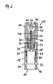
- FIG. 2 shows a guided in the axial direction section through the proximal end portion of a first embodiment of an intramedullary nail system according to the invention.
- An intramedullary nail system is shown for the stabilization and rest of fragments of a fractured bone, such as the tibial bone (tibia), the femur (femur) or the humerus.
- the intramedullary nail system comprises an approximately cylindrical nail body 12 and an opening of the nail body 12 at its proximal end 54 closing substantially axisymmetric end cap assembly 20.
- the nail body 12 has at its distal end 56 also has an opening, not shown.
- the openings at the proximal end 54 and at the distal end 56 are connected to each other via a cavity 10 in the nail body 12.
- One group of locking apertures 58, 60 is located at distal end 56, while the other group of locking apertures 62, 64 is provided at proximal end 54.
- a diametrically opposite slot pair 32, 34 is provided at the proximal end 54 of the nail body 12 .
- FIG. 1 shown intramedullary nail system is used in the context of osteosynthesis as follows.
- a guide spike (not shown) is inserted into the cavity of a fractured tubular bone beyond the fracture gap.
- the nail body 12 is guided over the guide spit in the long bones.
- the guide spike can be removed.
- one or more locking screws penetrating the bone shaft can be used, which give the bone stabilized by the nail body 12 additional rotational stability.
- Another shaft screw can be passed through the slots 32.
- the end cap assembly 20 includes a coil assembly 14, and in the screwed-on state of the end cap assembly 20 itself acts as an electrode, while the nail body 12 forms the counter electrode.
- the coil assembly 14 is disposed in a free volume of the end cap housing 22.
- the coil assembly 14 surrounds a soft iron core, which is provided for amplifying the externally supplied alternating magnetic field.
- One pole of the coil assembly 14 contacts a pad 76 of the end cap housing 22 via a parallel circuit of diode 36, ohmic resistor 42, and capacitive resistor 44.
- the rectifier circuit implemented by the diode 36 may have an advantageous effect on the localization of bone growth.
- the surface of the end cap housing 22 becomes the anode where bone growth is inhibited, or even osteolysis occurs, while the nail body 12 becomes the cathode, promoting bone growth particularly in the fracture area.
- the parallel to the diode 36 components that is, the resistor 42 and the capacitive resistor 44 are optional. It shifts the voltage profile in the direction of positive polarity in comparison to the non-rectified voltage in such a way that there is an incomplete rectification.
- the diode is dispensable, so that the first pole of the coil arrangement 14 can contact the end cap housing 22 directly.
- the other pole of the coil assembly 14 is located via a contact point 74 with a coil spring 28 in electrical contact.
- a electrical line 72 passed through a distal portion of the end cap housing, wherein an insulation 70 prevents an electrical short circuit of the coil assembly.
- the distal portion of the end cap assembly 20, which is tapered from the proximal portion, carries a thread.
- a threaded portion 26 the end cap assembly 20 is screwed into the nail body 12, wherein a short circuit of the coil assembly preventing insulating layer 24 is provided.
- This insulating layer 24 is advantageously continued in the proximal direction, for example until the insulation 66 at the transition between the proximal to the distal region of the end cap assembly 20.
- a compression screw 30 is further screwed over a threaded portion 68.
- this compression screw 30 serves to apply force to a shaft screw penetrating the elongated holes 32, 34 in the axial direction so that compression in the area of the fracture gap can take place.
- the compression screw 30 also serves to electrically contact the coil spring 28, which is supported at its proximal end to the insulation 24 and at its distal end to the compression screw 30.
- the electrical contact between the coil arrangement 14, that is to say in particular the contact point 74, and the nail body 12 is produced via the threaded region 68 and optionally via the oblong holes 32, 34 penetrating the shaft screw (not illustrated).
- the electrical components inside the end cap housing 22 are surrounded by a biocompatible Epoxidg discernharzmasse electrically insulating and mechanically stabilizing.
- FIG. 3 shows a guided in the axial direction section through the proximal end portion of a second embodiment of an intramedullary nail system according to the invention.
- an end cap housing 22 made of electrically insulating material, such as biocompatible polyethylene used.
- the contact surface is formed by an electrically conductive lid 90 which closes the end cap housing 22 at its proximal end.
- the lid 90 may be connected to the end cap housing by gluing, screwing, clipping or the like.
- a pouring of the housing interior is unnecessary, although still possible, for example, for the mechanical stabilization of the electrical components and connections.
- the related to FIG. 2 described insulation 24, 26, 70 of the end cap housing 22 against the nail body are in electrically insulating end cap housing 22 according to FIG. 3 dispensable.
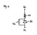
- FIGS. 4 and 5 show two embodiments of an applicable in connection with the invention rectifier circuit.
- the circuit in FIG. 4 is essentially the same as already based on FIG. 2 described circuit, although there is no capacitive resistance.
- the parallel connection of an ohmic resistor 62 may be dispensable depending on the application.
- FIG. 4 a half-wave rectifier circuit is in FIG. 5 a full-wave rectification shown.
- the coil assembly 14 has a center tap 78 from which it has an ohmic resistance 82 with a contact point 74th on nail body 12 and the coil spring 28 leading circuit node 80 is connected.
- the center tap 78 is further connected directly to the pad 76 on the end cap housing.
- two diodes 38, 40 are connected, which contact the two end points of the coil assembly.
- two diodes 38, 40 are connected, which contact the two end points of the coil assembly.
- FIG. 5 illustrated two-way rectifier circuit can be modified by the AC behavior of the circuit influencing resistors.
- FIG. 6 shows a radial section through a nail body of an intramedullary nail system according to the invention with magnetic rods arranged therein.
- the nail body 12 has a plurality of recesses 84 extending along its circumference and extending in the axial direction, which provide rotational stabilization of the nail body 12 in the bone.
- an insulating jacket 52 is provided with four bars 48, 50 arranged therein.
- Other variants are possible, namely a variation of the number of rods, an exclusive provision of soft magnetic material or an exclusive provision of unsaturated permanent magnetic material.
- the soft magnetic rods 48 bundle the externally supplied alternating magnetic field, so that there is a local reinforcement, which acts up to the area of the end cap assembly 20 provided in the coil assembly 14. Consequently, the soft magnetic rods 48 have a reinforcing Effect on the electrical power provided via the tissue electrodes.
- the unsaturated permanent magnetic rod 50 can partially follow the externally supplied alternating magnetic field, so that, unlike a saturated permanent magnetic rod, a "short circuit" of the magnetic field is prevented.
- the special effect of the permanent magnetic element comes into play in the absence of an external magnetic field, namely by the provision of a radially outwardly decreasing magnetic gradient field penetrating into the tissue region surrounding the nail body 12.
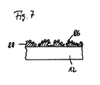
- FIG. 7 shows a section through the surface of a nail body of an intramedullary nail system according to the invention with a surface-enlarging coating.
- the outer surface of the nail body 12 is provided with a surface-increasing and the addition of bacteria-avoiding electrically conductive coating, preferably made of colloidal silver particles 26.
- the coating of the surface is made by a porous Intermediate layer 68 mediates, which consists for example of plastic or ceramic. It is also possible that the silver particles are additionally or alternatively incorporated in the intermediate layer. This can be realized by applying a ceramic-silver emulsion.
- the electrical contact between the surface of the nail body 12 and the electrically conductive coating 86 is provided via body fluid or by direct contact of the surface of the nail body 12 with the coating 86 in the region of the pores of the porous surface 88. Due to the bactericidal coating 86, the attachment of bacteria is hindered even without electrical potentials made available via the nail surface. This effect is enhanced in the context of the present invention by the induced electric fields. Furthermore, the effect of the induced electric field on the surrounding tissue is favored, since the electrically conductive coating 86 increases the contact surface between tissue and electrode. As a result, the positive biological effects can be improved thereby, or simpler and smaller devices can be used while maintaining a given quality, which relates in particular to the coil arrangement and the equipment generating the external alternating magnetic field.
Landscapes
- Health & Medical Sciences (AREA)
- Life Sciences & Earth Sciences (AREA)
- Orthopedic Medicine & Surgery (AREA)
- General Health & Medical Sciences (AREA)
- Nuclear Medicine, Radiotherapy & Molecular Imaging (AREA)
- Engineering & Computer Science (AREA)
- Biomedical Technology (AREA)
- Veterinary Medicine (AREA)
- Public Health (AREA)
- Animal Behavior & Ethology (AREA)
- Radiology & Medical Imaging (AREA)
- Surgery (AREA)
- Molecular Biology (AREA)
- Medical Informatics (AREA)
- Heart & Thoracic Surgery (AREA)
- Cell Biology (AREA)
- Neurology (AREA)
- Surgical Instruments (AREA)
- Magnetic Treatment Devices (AREA)
- Mechanical Pencils And Projecting And Retracting Systems Therefor, And Multi-System Writing Instruments (AREA)
- Electrotherapy Devices (AREA)
Applications Claiming Priority (1)
| Application Number | Priority Date | Filing Date | Title |
|---|---|---|---|
| DE102006018191A DE102006018191B4 (de) | 2006-04-19 | 2006-04-19 | Elektrisches Marknagelsystem |
Publications (2)
| Publication Number | Publication Date |
|---|---|
| EP1847227A1 EP1847227A1 (de) | 2007-10-24 |
| EP1847227B1 true EP1847227B1 (de) | 2008-11-12 |
Family
ID=38222709
Family Applications (1)
| Application Number | Title | Priority Date | Filing Date |
|---|---|---|---|
| EP07006869A Active EP1847227B1 (de) | 2006-04-19 | 2007-04-02 | Elektrisches Marknagelsystem |
Country Status (10)
| Country | Link |
|---|---|
| US (1) | US9439694B2 (enExample) |
| EP (1) | EP1847227B1 (enExample) |
| JP (1) | JP4162051B2 (enExample) |
| CN (1) | CN101431956B (enExample) |
| AT (1) | ATE413847T1 (enExample) |
| AU (1) | AU2007201642B2 (enExample) |
| CA (1) | CA2585220C (enExample) |
| DE (2) | DE102006018191B4 (enExample) |
| ES (1) | ES2316112T3 (enExample) |
| WO (1) | WO2007118457A1 (enExample) |
Cited By (1)
| Publication number | Priority date | Publication date | Assignee | Title |
|---|---|---|---|---|
| US11457934B2 (en) | 2018-07-24 | 2022-10-04 | DePuy Synthes Products, Inc. | Intramedullary nail with wire or magnet for targeting of a bone-anchor locking hole |
Families Citing this family (28)
| Publication number | Priority date | Publication date | Assignee | Title |
|---|---|---|---|---|
| DE102006018191B4 (de) | 2006-04-19 | 2008-08-07 | Neue Magnetodyn Gmbh | Elektrisches Marknagelsystem |
| DE102007063027A1 (de) * | 2007-12-28 | 2009-07-09 | Neue Magnetodyn Gmbh | Kontaktvorrichtung für die Osteosynthese |
| DE102008020193B4 (de) * | 2008-04-16 | 2017-07-06 | Aesculap Ag | Tibianagel |
| DE102008021574A1 (de) * | 2008-04-30 | 2009-11-05 | Neue Magnetodyn Gmbh | Vorrichtung zum Stimulieren eines Heilungsprozesses im Bereich eines Implantats |
| EP2282689B1 (en) * | 2008-05-07 | 2013-02-13 | Tornier | Apparatus for proximal humeral fracture repair |
| DE102008033805A1 (de) * | 2008-07-18 | 2010-01-21 | Neue Magnetodyn Gmbh | System zum Erfassen von Messwerten in oder an einem Organismus und Verfahren zum Herstellen einer Komponente dieses Systems |
| US10251757B2 (en) * | 2008-09-17 | 2019-04-09 | Skeletal Dynamics Llc | Grooved slot allowing adjustment of the position of a bone fixation device for osteosynthesis |
| EP2429444B1 (en) | 2009-05-11 | 2024-02-28 | TriAgenics, Inc. | Therapeutic tooth bud ablation |
| US10022202B2 (en) | 2013-03-15 | 2018-07-17 | Triagenics, Llc | Therapeutic tooth bud ablation |
| WO2014143014A1 (en) | 2013-03-15 | 2014-09-18 | Triagenics, Llc | Therapeutic tooth bud ablation |
| DE102009049175A1 (de) | 2009-10-13 | 2011-04-21 | Bjarne Geiges | Vorrichtung zum Verabreichen von Arzneimitteln und zum Beeinflussen von Arzneimittelwirkungen |
| US8556896B2 (en) * | 2010-01-27 | 2013-10-15 | Zimmer, Inc. | Distal relief for a surgical device |
| USD638126S1 (en) * | 2010-04-13 | 2011-05-17 | Zimmer, Gmbh | Intramedullary nail |
| USD638125S1 (en) * | 2010-04-13 | 2011-05-17 | Zimmer, Gmbh | Intramedullary nail |
| FR2962047B1 (fr) * | 2010-07-05 | 2013-11-29 | Oreal | Dispositif de traitement magnetoelectrique |
| US20130165733A1 (en) * | 2011-12-27 | 2013-06-27 | Richard A. Rogachefsky | Orthopedic fixation device with magnetic field generator |
| US9438264B1 (en) | 2015-09-10 | 2016-09-06 | Realtek Semiconductor Corp. | High-speed capacitive digital-to-analog converter and method thereof |
| US10335282B2 (en) | 2016-02-09 | 2019-07-02 | Richard A. Rogachefsky | Magnetic joint replacement |
| US10751527B2 (en) | 2016-10-03 | 2020-08-25 | II Erich W. Wolf | Device and method for percutaneous placement and anchoring of stimulating electrodes in spine |
| CN106621074A (zh) * | 2016-11-08 | 2017-05-10 | 武汉瑞祥安精密制造有限责任公司 | 一种绝缘绝热伽马刀立体定位框架头钉 |
| WO2019075119A1 (en) | 2017-10-11 | 2019-04-18 | Tornier, Inc. | HUMERAL FIXATION PLATE GUIDES |
| EP3773280A1 (en) | 2018-04-10 | 2021-02-17 | DePuy Synthes Products, Inc. | Bipolar bone anchor with connection for electrostimulation |
| WO2020008309A1 (en) * | 2018-07-01 | 2020-01-09 | Petric Zoran Lee | A bone implant |
| US11596803B2 (en) | 2018-08-02 | 2023-03-07 | Richard A. Rogachefsky | Orthopedic treatment device with electromagnetic field generator |
| EP3924044B1 (en) * | 2019-02-13 | 2024-10-23 | Pulsar Medtech Ltd. | Implantable electromagnetic field generator for orthopedic therapy |
| EP4413935A3 (en) | 2019-06-06 | 2024-09-18 | TriAgenics, Inc. | Ablation probe systems |
| DE102019122354A1 (de) * | 2019-08-20 | 2021-02-25 | Orthofix Srl | Marknagel für eine Distraktion eines Röhrenknochens |
| US20230067388A1 (en) * | 2021-08-24 | 2023-03-02 | Intelligent Implants Limited | System for a dynamic electrically stimulating rod-like orthopedic implant |
Family Cites Families (24)
| Publication number | Priority date | Publication date | Assignee | Title |
|---|---|---|---|---|
| CA244914A (en) | 1924-12-02 | H. Rogers Frank | Gate operating mechanism | |
| DE2636818C2 (de) * | 1976-08-16 | 1987-01-15 | Werner Dipl.-Ing. 8000 München Kraus | Elektro-Marknagel |
| DE2742741A1 (de) * | 1977-09-22 | 1979-04-05 | Kraus Werner | Zusatzvorrichtung zum anbringen von einer aufnehmerspule und elektrodenanschluessen an einem osteosyntheseimplantat |
| CH618610A5 (en) * | 1978-01-17 | 1980-08-15 | Ivanov Mihail Tzvetkov | Implant for the stimulation of callus formation |
| US5030236A (en) * | 1989-06-19 | 1991-07-09 | Intermedics Orthopedics, Inc. | Apparatus for enhancing biointegration of bony and endoprosthesis structures |
| DE4318150C2 (de) * | 1993-06-01 | 1996-08-01 | Endocare Ag | Osteosynthese-Hilfsmittel zur Versorgung subtrochanterer und pertrochanterer Frakturen sowie von Schenkelhalsfrakturen |
| US5292252A (en) * | 1992-12-14 | 1994-03-08 | Impla-Med, Inc. | Stimulator healing cap |
| DE19544750A1 (de) * | 1995-11-30 | 1997-06-05 | Christoph Rehberg | Implantierbare Vorrichtung mit Innenelektrode zur Förderung des Gewebewachstums |
| US5725377A (en) * | 1996-03-29 | 1998-03-10 | Lemler; Jeffrey Richard | Dental implant apparatus |
| DE19709514C1 (de) * | 1996-12-18 | 1998-11-12 | Eska Implants Gmbh & Co | Prophylaxe-Implantat gegen Frakturen osteoporotisch befallener Knochensegmente |
| US6139552A (en) * | 1998-05-13 | 2000-10-31 | K. K. Hollyx | Bone jointer and a bone jointer fixing tool |
| DE19906423A1 (de) * | 1999-02-16 | 2000-08-17 | Wittenstein Gmbh & Co Kg | Aktiver Marknagel zur Distraktion von Knochenteilen |
| DE19928449C1 (de) * | 1999-06-23 | 2001-03-08 | Geot Ges Fuer Elektro Oseto Th | Knochenschraube mit Vorrichtung zur Elektrostimulation |
| DE10055519A1 (de) * | 2000-11-09 | 2002-06-06 | Wittenstein Gmbh & Co Kg | Distraktionsvorrichtung |
| US6610096B2 (en) * | 2001-08-22 | 2003-08-26 | Macdonald Stuart G. | Prosthetic implants having enhanced utility |
| CN2525953Y (zh) * | 2002-03-04 | 2002-12-18 | 陈唯宁 | 髓内钉 |
| US7615070B2 (en) * | 2002-10-11 | 2009-11-10 | Spineco, Inc. | Electro-stimulation and medical delivery device |
| US20040073221A1 (en) * | 2002-10-11 | 2004-04-15 | Spineco, Inc., A Corporation Of Ohio | Electro-stimulation and medical delivery device |
| US20050055024A1 (en) * | 2003-09-08 | 2005-03-10 | James Anthony H. | Orthopaedic implant and screw assembly |
| US8070785B2 (en) * | 2003-09-16 | 2011-12-06 | Spineco, Inc. | Bone anchor prosthesis and system |
| US7389140B1 (en) * | 2004-06-16 | 2008-06-17 | Kroll Mark W | Adjustment of stimulation current path |
| US20060004431A1 (en) * | 2004-07-01 | 2006-01-05 | Fuller Thomas A | Prophylactic bactericidal implant |
| DE102006018191B4 (de) | 2006-04-19 | 2008-08-07 | Neue Magnetodyn Gmbh | Elektrisches Marknagelsystem |
| US8380319B2 (en) * | 2007-04-11 | 2013-02-19 | J. Lee Berger | Electrical screw |
-
2006
- 2006-04-19 DE DE102006018191A patent/DE102006018191B4/de not_active Expired - Fee Related
-
2007
- 2007-04-02 ES ES07006869T patent/ES2316112T3/es active Active
- 2007-04-02 AT AT07006869T patent/ATE413847T1/de not_active IP Right Cessation
- 2007-04-02 DE DE502007000228T patent/DE502007000228D1/de active Active
- 2007-04-02 EP EP07006869A patent/EP1847227B1/de active Active
- 2007-04-12 WO PCT/DE2007/000640 patent/WO2007118457A1/de not_active Ceased
- 2007-04-12 CN CN2007800140096A patent/CN101431956B/zh not_active Expired - Fee Related
- 2007-04-13 AU AU2007201642A patent/AU2007201642B2/en not_active Ceased
- 2007-04-17 US US11/736,173 patent/US9439694B2/en not_active Expired - Fee Related
- 2007-04-18 CA CA002585220A patent/CA2585220C/en not_active Expired - Fee Related
- 2007-04-19 JP JP2007110806A patent/JP4162051B2/ja not_active Expired - Fee Related
Cited By (2)
| Publication number | Priority date | Publication date | Assignee | Title |
|---|---|---|---|---|
| US11457934B2 (en) | 2018-07-24 | 2022-10-04 | DePuy Synthes Products, Inc. | Intramedullary nail with wire or magnet for targeting of a bone-anchor locking hole |
| US12167859B2 (en) | 2018-07-24 | 2024-12-17 | DePuy Synthes Products, Inc. | Intramedullary nail with wire or magnet for targeting of a bone-anchor locking hole |
Also Published As
| Publication number | Publication date |
|---|---|
| CA2585220A1 (en) | 2007-10-19 |
| WO2007118457A1 (de) | 2007-10-25 |
| AU2007201642B2 (en) | 2008-12-18 |
| JP4162051B2 (ja) | 2008-10-08 |
| CN101431956B (zh) | 2011-05-04 |
| ATE413847T1 (de) | 2008-11-15 |
| DE102006018191A1 (de) | 2007-10-25 |
| DE502007000228D1 (de) | 2008-12-24 |
| ES2316112T3 (es) | 2009-04-01 |
| CN101431956A (zh) | 2009-05-13 |
| EP1847227A1 (de) | 2007-10-24 |
| JP2007283110A (ja) | 2007-11-01 |
| US9439694B2 (en) | 2016-09-13 |
| DE102006018191B4 (de) | 2008-08-07 |
| CA2585220C (en) | 2009-12-08 |
| AU2007201642A1 (en) | 2007-11-08 |
| US20070265628A1 (en) | 2007-11-15 |
Similar Documents
| Publication | Publication Date | Title |
|---|---|---|
| EP1847227B1 (de) | Elektrisches Marknagelsystem | |
| EP2012869B1 (de) | Stimulationsvorrichtung für die osteosynthese und die endoprothetik | |
| EP2467190B1 (de) | Polarisationsvorrichtung und implantationssystem | |
| WO2009083086A2 (de) | Kontaktvorrichtung für die osteosynthese | |
| EP1408857B1 (de) | Knochenschraube mit vorrichtung zur elektrostimulation | |
| EP2050482B1 (de) | Implantierbare Vorrichtung, System zum Erzeugen lokalisierter elektromagnetischer Felder im Bereich eines Implantats und Spulenanordnung | |
| EP2130566B1 (de) | Langgestrecktes Implantat mit externer Energieeinkopplung | |
| DE2314573A1 (de) | Geraet zur foerderung von heilungsprozessen | |
| EP2124783B1 (de) | Implantat zur frakturversorgung | |
| WO2014023281A2 (de) | Elektrodenanordnung für eine plasmabehandlung und vorrichtung zur herstellung einer transkutanen verbindung | |
| DE102004055866A1 (de) | Gerät zur Zerstörung von Tumorgewebe | |
| EP1607066A1 (de) | Hüftkopfkappenimplantat mit Vorrichtung zur elektrischen Gewebestimulation | |
| AT520250B1 (de) | Knochenschraube | |
| EP2421475B1 (de) | Elektrische hüftgelenkprothese | |
| EP2377574A2 (de) | Implantat und Applikator | |
| EP3148464B1 (de) | Vorrichtung zur biologischen dekontamination von perkutanen zugängen und verfahren hierzu | |
| WO2001072233A1 (de) | Interferenzschraube aus knochenmaterial | |
| DE10009830A1 (de) | Temporäre Herzschrittmacher-Leitung | |
| WO2014029033A1 (de) | Klemmelement und vorrichtung zur stabilisierung von knochen | |
| WO2016150695A1 (de) | Implantierbare vorrichtung zum ausbilden einer permanenten hautdurchführung |
Legal Events
| Date | Code | Title | Description |
|---|---|---|---|
| PUAI | Public reference made under article 153(3) epc to a published international application that has entered the european phase |
Free format text: ORIGINAL CODE: 0009012 |
|
| AK | Designated contracting states |
Kind code of ref document: A1 Designated state(s): AT BE BG CH CY CZ DE DK EE ES FI FR GB GR HU IE IS IT LI LT LU LV MC MT NL PL PT RO SE SI SK TR |
|
| AX | Request for extension of the european patent |
Extension state: AL BA HR MK YU |
|
| 17P | Request for examination filed |
Effective date: 20080226 |
|
| GRAP | Despatch of communication of intention to grant a patent |
Free format text: ORIGINAL CODE: EPIDOSNIGR1 |
|
| AKX | Designation fees paid |
Designated state(s): AT BE BG CH CY CZ DE DK EE ES FI FR GB GR HU IE IS IT LI LT LU LV MC MT NL PL PT RO SE SI SK TR |
|
| GRAS | Grant fee paid |
Free format text: ORIGINAL CODE: EPIDOSNIGR3 |
|
| GRAA | (expected) grant |
Free format text: ORIGINAL CODE: 0009210 |
|
| AK | Designated contracting states |
Kind code of ref document: B1 Designated state(s): AT BE BG CH CY CZ DE DK EE ES FI FR GB GR HU IE IS IT LI LT LU LV MC MT NL PL PT RO SE SI SK TR |
|
| REG | Reference to a national code |
Ref country code: GB Ref legal event code: FG4D Free format text: NOT ENGLISH |
|
| REG | Reference to a national code |
Ref country code: CH Ref legal event code: EP |
|
| REG | Reference to a national code |
Ref country code: IE Ref legal event code: FG4D Free format text: LANGUAGE OF EP DOCUMENT: GERMAN |
|
| REF | Corresponds to: |
Ref document number: 502007000228 Country of ref document: DE Date of ref document: 20081224 Kind code of ref document: P |
|
| REG | Reference to a national code |
Ref country code: CH Ref legal event code: NV Representative=s name: R. A. EGLI & CO. PATENTANWAELTE |
|
| REG | Reference to a national code |
Ref country code: ES Ref legal event code: FG2A Ref document number: 2316112 Country of ref document: ES Kind code of ref document: T3 |
|
| LTIE | Lt: invalidation of european patent or patent extension |
Effective date: 20081112 |
|
| PG25 | Lapsed in a contracting state [announced via postgrant information from national office to epo] |
Ref country code: LT Free format text: LAPSE BECAUSE OF FAILURE TO SUBMIT A TRANSLATION OF THE DESCRIPTION OR TO PAY THE FEE WITHIN THE PRESCRIBED TIME-LIMIT Effective date: 20081112 |
|
| NLV1 | Nl: lapsed or annulled due to failure to fulfill the requirements of art. 29p and 29m of the patents act | ||
| PG25 | Lapsed in a contracting state [announced via postgrant information from national office to epo] |
Ref country code: LV Free format text: LAPSE BECAUSE OF FAILURE TO SUBMIT A TRANSLATION OF THE DESCRIPTION OR TO PAY THE FEE WITHIN THE PRESCRIBED TIME-LIMIT Effective date: 20081112 Ref country code: NL Free format text: LAPSE BECAUSE OF FAILURE TO SUBMIT A TRANSLATION OF THE DESCRIPTION OR TO PAY THE FEE WITHIN THE PRESCRIBED TIME-LIMIT Effective date: 20081112 Ref country code: SI Free format text: LAPSE BECAUSE OF FAILURE TO SUBMIT A TRANSLATION OF THE DESCRIPTION OR TO PAY THE FEE WITHIN THE PRESCRIBED TIME-LIMIT Effective date: 20081112 Ref country code: IS Free format text: LAPSE BECAUSE OF FAILURE TO SUBMIT A TRANSLATION OF THE DESCRIPTION OR TO PAY THE FEE WITHIN THE PRESCRIBED TIME-LIMIT Effective date: 20090312 Ref country code: FI Free format text: LAPSE BECAUSE OF FAILURE TO SUBMIT A TRANSLATION OF THE DESCRIPTION OR TO PAY THE FEE WITHIN THE PRESCRIBED TIME-LIMIT Effective date: 20081112 Ref country code: PL Free format text: LAPSE BECAUSE OF FAILURE TO SUBMIT A TRANSLATION OF THE DESCRIPTION OR TO PAY THE FEE WITHIN THE PRESCRIBED TIME-LIMIT Effective date: 20081112 |
|
| REG | Reference to a national code |
Ref country code: IE Ref legal event code: FD4D |
|
| PG25 | Lapsed in a contracting state [announced via postgrant information from national office to epo] |
Ref country code: EE Free format text: LAPSE BECAUSE OF FAILURE TO SUBMIT A TRANSLATION OF THE DESCRIPTION OR TO PAY THE FEE WITHIN THE PRESCRIBED TIME-LIMIT Effective date: 20081112 Ref country code: DK Free format text: LAPSE BECAUSE OF FAILURE TO SUBMIT A TRANSLATION OF THE DESCRIPTION OR TO PAY THE FEE WITHIN THE PRESCRIBED TIME-LIMIT Effective date: 20081112 Ref country code: RO Free format text: LAPSE BECAUSE OF FAILURE TO SUBMIT A TRANSLATION OF THE DESCRIPTION OR TO PAY THE FEE WITHIN THE PRESCRIBED TIME-LIMIT Effective date: 20081112 Ref country code: IE Free format text: LAPSE BECAUSE OF FAILURE TO SUBMIT A TRANSLATION OF THE DESCRIPTION OR TO PAY THE FEE WITHIN THE PRESCRIBED TIME-LIMIT Effective date: 20081112 Ref country code: BG Free format text: LAPSE BECAUSE OF FAILURE TO SUBMIT A TRANSLATION OF THE DESCRIPTION OR TO PAY THE FEE WITHIN THE PRESCRIBED TIME-LIMIT Effective date: 20090212 |
|
| PG25 | Lapsed in a contracting state [announced via postgrant information from national office to epo] |
Ref country code: PT Free format text: LAPSE BECAUSE OF FAILURE TO SUBMIT A TRANSLATION OF THE DESCRIPTION OR TO PAY THE FEE WITHIN THE PRESCRIBED TIME-LIMIT Effective date: 20090413 Ref country code: CZ Free format text: LAPSE BECAUSE OF FAILURE TO SUBMIT A TRANSLATION OF THE DESCRIPTION OR TO PAY THE FEE WITHIN THE PRESCRIBED TIME-LIMIT Effective date: 20081112 Ref country code: SE Free format text: LAPSE BECAUSE OF FAILURE TO SUBMIT A TRANSLATION OF THE DESCRIPTION OR TO PAY THE FEE WITHIN THE PRESCRIBED TIME-LIMIT Effective date: 20090212 |
|
| PLBE | No opposition filed within time limit |
Free format text: ORIGINAL CODE: 0009261 |
|
| STAA | Information on the status of an ep patent application or granted ep patent |
Free format text: STATUS: NO OPPOSITION FILED WITHIN TIME LIMIT |
|
| PG25 | Lapsed in a contracting state [announced via postgrant information from national office to epo] |
Ref country code: SK Free format text: LAPSE BECAUSE OF FAILURE TO SUBMIT A TRANSLATION OF THE DESCRIPTION OR TO PAY THE FEE WITHIN THE PRESCRIBED TIME-LIMIT Effective date: 20081112 |
|
| 26N | No opposition filed |
Effective date: 20090813 |
|
| BERE | Be: lapsed |
Owner name: NEUE MAGNETODYN G.M.B.H. Effective date: 20090430 |
|
| PG25 | Lapsed in a contracting state [announced via postgrant information from national office to epo] |
Ref country code: MC Free format text: LAPSE BECAUSE OF NON-PAYMENT OF DUE FEES Effective date: 20090430 |
|
| PG25 | Lapsed in a contracting state [announced via postgrant information from national office to epo] |
Ref country code: BE Free format text: LAPSE BECAUSE OF NON-PAYMENT OF DUE FEES Effective date: 20090430 |
|
| PG25 | Lapsed in a contracting state [announced via postgrant information from national office to epo] |
Ref country code: AT Free format text: LAPSE BECAUSE OF NON-PAYMENT OF DUE FEES Effective date: 20090402 |
|
| PG25 | Lapsed in a contracting state [announced via postgrant information from national office to epo] |
Ref country code: GR Free format text: LAPSE BECAUSE OF FAILURE TO SUBMIT A TRANSLATION OF THE DESCRIPTION OR TO PAY THE FEE WITHIN THE PRESCRIBED TIME-LIMIT Effective date: 20090213 |
|
| PG25 | Lapsed in a contracting state [announced via postgrant information from national office to epo] |
Ref country code: IT Free format text: LAPSE BECAUSE OF NON-PAYMENT OF DUE FEES Effective date: 20100402 |
|
| PG25 | Lapsed in a contracting state [announced via postgrant information from national office to epo] |
Ref country code: LU Free format text: LAPSE BECAUSE OF NON-PAYMENT OF DUE FEES Effective date: 20090402 |
|
| PG25 | Lapsed in a contracting state [announced via postgrant information from national office to epo] |
Ref country code: HU Free format text: LAPSE BECAUSE OF FAILURE TO SUBMIT A TRANSLATION OF THE DESCRIPTION OR TO PAY THE FEE WITHIN THE PRESCRIBED TIME-LIMIT Effective date: 20090513 |
|
| PG25 | Lapsed in a contracting state [announced via postgrant information from national office to epo] |
Ref country code: TR Free format text: LAPSE BECAUSE OF FAILURE TO SUBMIT A TRANSLATION OF THE DESCRIPTION OR TO PAY THE FEE WITHIN THE PRESCRIBED TIME-LIMIT Effective date: 20081112 |
|
| PG25 | Lapsed in a contracting state [announced via postgrant information from national office to epo] |
Ref country code: CY Free format text: LAPSE BECAUSE OF FAILURE TO SUBMIT A TRANSLATION OF THE DESCRIPTION OR TO PAY THE FEE WITHIN THE PRESCRIBED TIME-LIMIT Effective date: 20081112 |
|
| PGFP | Annual fee paid to national office [announced via postgrant information from national office to epo] |
Ref country code: CH Payment date: 20110726 Year of fee payment: 5 |
|
| PGFP | Annual fee paid to national office [announced via postgrant information from national office to epo] |
Ref country code: IT Payment date: 20120427 Year of fee payment: 6 |
|
| PGFP | Annual fee paid to national office [announced via postgrant information from national office to epo] |
Ref country code: ES Payment date: 20120524 Year of fee payment: 6 |
|
| REG | Reference to a national code |
Ref country code: CH Ref legal event code: PL |
|
| PG25 | Lapsed in a contracting state [announced via postgrant information from national office to epo] |
Ref country code: LI Free format text: LAPSE BECAUSE OF NON-PAYMENT OF DUE FEES Effective date: 20130430 Ref country code: CH Free format text: LAPSE BECAUSE OF NON-PAYMENT OF DUE FEES Effective date: 20130430 |
|
| PG25 | Lapsed in a contracting state [announced via postgrant information from national office to epo] |
Ref country code: IT Free format text: LAPSE BECAUSE OF NON-PAYMENT OF DUE FEES Effective date: 20130402 |
|
| REG | Reference to a national code |
Ref country code: ES Ref legal event code: FD2A Effective date: 20140611 |
|
| PG25 | Lapsed in a contracting state [announced via postgrant information from national office to epo] |
Ref country code: ES Free format text: LAPSE BECAUSE OF NON-PAYMENT OF DUE FEES Effective date: 20130403 |
|
| REG | Reference to a national code |
Ref country code: FR Ref legal event code: PLFP Year of fee payment: 9 |
|
| REG | Reference to a national code |
Ref country code: FR Ref legal event code: PLFP Year of fee payment: 10 |
|
| REG | Reference to a national code |
Ref country code: FR Ref legal event code: PLFP Year of fee payment: 11 |
|
| REG | Reference to a national code |
Ref country code: FR Ref legal event code: PLFP Year of fee payment: 12 |
|
| PGFP | Annual fee paid to national office [announced via postgrant information from national office to epo] |
Ref country code: DE Payment date: 20200423 Year of fee payment: 14 |
|
| REG | Reference to a national code |
Ref country code: DE Ref legal event code: R119 Ref document number: 502007000228 Country of ref document: DE |
|
| PG25 | Lapsed in a contracting state [announced via postgrant information from national office to epo] |
Ref country code: DE Free format text: LAPSE BECAUSE OF NON-PAYMENT OF DUE FEES Effective date: 20211103 |
|
| PGFP | Annual fee paid to national office [announced via postgrant information from national office to epo] |
Ref country code: FR Payment date: 20221027 Year of fee payment: 16 |
|
| PGFP | Annual fee paid to national office [announced via postgrant information from national office to epo] |
Ref country code: GB Payment date: 20221027 Year of fee payment: 16 |
|
| GBPC | Gb: european patent ceased through non-payment of renewal fee |
Effective date: 20230402 |
|
| PG25 | Lapsed in a contracting state [announced via postgrant information from national office to epo] |
Ref country code: GB Free format text: LAPSE BECAUSE OF NON-PAYMENT OF DUE FEES Effective date: 20230402 |
|
| PG25 | Lapsed in a contracting state [announced via postgrant information from national office to epo] |
Ref country code: GB Free format text: LAPSE BECAUSE OF NON-PAYMENT OF DUE FEES Effective date: 20230402 Ref country code: FR Free format text: LAPSE BECAUSE OF NON-PAYMENT OF DUE FEES Effective date: 20230430 |