EP1846279B1 - Vehicle front-part structure - Google Patents
Vehicle front-part structure Download PDFInfo
- Publication number
- EP1846279B1 EP1846279B1 EP06713246A EP06713246A EP1846279B1 EP 1846279 B1 EP1846279 B1 EP 1846279B1 EP 06713246 A EP06713246 A EP 06713246A EP 06713246 A EP06713246 A EP 06713246A EP 1846279 B1 EP1846279 B1 EP 1846279B1
- Authority
- EP
- European Patent Office
- Prior art keywords
- vehicle
- framework
- hood
- radiator support
- face
- Prior art date
- Legal status (The legal status is an assumption and is not a legal conclusion. Google has not performed a legal analysis and makes no representation as to the accuracy of the status listed.)
- Expired - Lifetime
Links
Images


Classifications
-
- B—PERFORMING OPERATIONS; TRANSPORTING
- B62—LAND VEHICLES FOR TRAVELLING OTHERWISE THAN ON RAILS
- B62D—MOTOR VEHICLES; TRAILERS
- B62D21/00—Understructures, i.e. chassis frame on which a vehicle body may be mounted
- B62D21/15—Understructures, i.e. chassis frame on which a vehicle body may be mounted having impact absorbing means, e.g. a frame designed to permanently or temporarily change shape or dimension upon impact with another body
- B62D21/152—Front or rear frames
Definitions
- the present invention relates to a vehicle front-part structure.
- a radiator support upper that supports the upper portion of the radiator has the structure in which the crash load cannot sufficiently be received, and a member which receives the crash load does not exist in an upper portion of a vehicle front. Therefore, a distribution of the crash load acting on the vehicle front-part is biased in a lower portion of the vehicle front where the front bumper reinforcement and the like are located, and load uniformity is lost in the vehicle front in the front crash.
- one object of the present invention is to provide a vehicle front-part structure which can receive the crash load in the crash even in the upper portion of the vehicle front.
- a vehicle front-part structure comprising: a radiator support upper which extends in a vehicle width direction in a vehicle front; a vehicle upper frameworkmember which is coupled to an apron upper member provided on a side in the vehicle width direction and extending in a vehicle lengthwise direction, and which is located to rearward of the vehicle further than the radiator support upper; and a hood framework which constitutes a part of the hood framework member, the hood framework extending in the vehicle lengthwise direction, the hood framework being disposed between the radiator support upper and the vehicle upper framework member such that at least a part of a front end-face faces the radiator support upper and at least a part of a rear end-face faces the vehicle upper framework member.
- the crash load when in the front crash of the vehicle, the crash load is transmitted from the radiator support upper to the vehicle upper framework member through the hood framework. Then, the crash load is transmitted from the vehicle upper framework member to the apron upper member and is further transmitted to rearward of the vehicle. Therefore, the crash load applied to the vehicle upper portion can be efficiently transmitted to rearward of the vehicle. Furthermore, in the case that an engine room is opened by operating a hood, the hood framework moves to the upside of the vehicle along with the hood, so that the hood framework does not obstruct maintenance of the engine or the like.
- the whole of the front end-face of the hood framework may face the radiator support upper, and the whole of the rear end-face of the hood framework may face the vehicle upper framework member.
- the crash load can be transmitted more securely when compared with the mode in which a part of the front end-face faces the radiator support upper and a part of the rear end-face faces the vehicle upper framework member.
- the end face of the hood framework there is included not only the mode in which the material exists in all the end face (for example, the end face formed by a solid-core member) but also the mode in which the material does not exist in all the end face (for example, the end face made of H-shaped or C-shaped steel, and the end face formed by a hollow member such as a pipe). Accordingly, it is sufficient that the material facing the radiator support upper and the vehicle upper framework member exist in the hood framework.
- any member may be employed as the vehicle upper framework member that receives the crash load through the hood framework, as long as the member is coupled to the apron upper member with a predetermined strength.
- the vehicle upper framework member may be a cowl extending in the vehicle width direction at a lower end of a wind shield, or may be a suspension tower.
- the crash load is transmitted from the radiator support upper to the cowl or the suspension tower through the hood framework, so that the crash load applied to the vehicle upper portion can be efficiently transmitted to rearward of the vehicle.
- the vehicle upper frameworkmember may be a dash panel which partitions the engine room and the cabin.
- a load transmission member may be provided between the suspension tower and a cowl extending in the vehicle width direction at a lower end of a wind shield. If the distance between the radiator support upper and the cowl is lengthened, a length of the member disposed between the radiator support upper and the cowl is increased, thereby raising the possibility that the bending moment is generated. If the bending moment is generated in the member, transmission efficiency of the crash load becomes worsened. According to the above embodiment, the crash load transmitted in the hood framework is transmitted to the cowl through the suspension tower and further thorough the load transmission member.
- the hood framework can be shortenedwhen compared with the case in which the hood framework is disposed between the radiator support upper and the cowl, so that the generation of the bending moment is suppressed to thereby efficiently transmit the crash load to rearward of the vehicle.
- the vehicle front-part structure may comprise a front-part constraint device which has: a projection which is provided on one of the front end-face of the hood framework and the radiator support upper; and a recess which is provided on the other of the front end-face of the hood framework and the radiator support upper, and the hood framework and the radiator support upper may be able to constrain each other by accommodating the projection in the recess.
- the hood framework and the radiator support upper are constrained by the front-part constraint device, so that occurrence, in which relative position displacement is generated between the hood framework and the radiator support upper and these members miss each other so as to obstruct the load transmission, can be avoided when in the front crash of the vehicle.
- timing at which the hood framework and the radiator support upper are constrained by the front-part constraint device it is sufficient that these members are constrained at the time of crash, and those members may also be constrained during the time except for the crash.
- the vehicle front-part structure may comprise a rear-part constraint device which has: a projection which is provided on one of the rear end-face of the hood framework and the vehicle upper framework member; and a recess which is provided on the other of the rear end-face of the hood framework and the vehicle upper framework member, and the hood framework and the vehicle upper framework member may be able to constrain each other by accommodating the projection in the recess.
- the hood framework and the vehicle upper framework member are constrained by the rear-part constraint device, so that occurrence, in which relative position displacement is generated between the hood framework and the vehicle upper frameworkmember and these members miss each other to obstruct the load transmission, can be avoided when in the front crash of the vehicle.
- timing at which the hood framework and the vehicle upper framework member are constrained by the rear-part constraint device it is sufficient that these members are constrained at the time of crash, and these members may also be constrained during the time except for the crash.
- the vehicle front-part structure may comprise a coupling device which has a retaining member provided on one of an intermediate portion of the hood framework and the suspension tower, and the hood framework and the suspension tower may be able to be coupled to each other by engaging the retaining member with the other of the intermediate portion of the hood framework and the suspension tower.
- a connection point is formed between the suspension tower and the intermediate portion of the hood framework by the retainingmember. Therefore, the number of connection points between the vehicle and the hood (including hood framework) is increased, so that the generation of the bending moment can be suppressed in the hood and the hood framework to thereby efficiently transmit the crash load in the front crash.
- the hood framework of which at least a part of the front end-face faces the radiator support upper while at least a part of the rear end-face faces the vehicle upper framework member is included, the crash load when in the crash can be received even in the upper portion of the vehicle front.
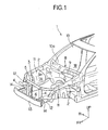
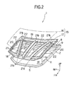
- FIGS. 1 and 2 show a vehicle front-part structure according to the first embodiment of the present invention
- FIG. 1 shows the vehicle front-part structure of which the hood is taken out
- FIG. 2 schematically shows the vehicle front-part structure in order to facilitate understanding the same.
- the sign UP denotes an upward direction of the vehicle
- the sign FR denotes a frontward direction of the vehicle
- the sign IN denotes an inward direction of the vehicle (the same holds in the following drawings).
- a vehicle 1 includes a pair of apron upper members 2 and 2 which are provided on both sides in the vehicle width direction and which extend in a vehicle lengthwise direction.
- a radiator support apparatus 3 including a pair of radiator support sides 4 and 4 which support a radiator (not shown) from the both sides thereof, a radiator support upper 5 which supports an upper side of the radiator, and a radiator support lower 6 which supports a lower side of the radiator.
- the radiator support sides 4 and 4, the radiator support upper 5, and the radiator support lower 6 are combined with each other by fastening means such as bolts (not shown) to support the radiator.
- the radiator support sides 4 are connected to the apron upper members 2, respectively.
- a dash panel 8 which partitions an engine room 1A and a cabin 1B of the vehicle 1 is provided to the rearward of the vehicle further than the radiator support upper 5, and both sides of the dash panel 8 in the vehicle width direction are joined to the apron upper members 2 and 2 by joining means such as welding.
- a cowl 9 which extends in the vehicle width direction in a lower end 10a of a wind shield 10 is provided forward of the vehicle further than the dash panel 8, and both sides of the cowl 9 are joined to the apron upper members 2 and 2 by the joining means such as the welding such that the cowl 9 and the dash panel 8 are arranged side by side in the vehicle lengthwise direction.
- a suspension tower 11 which supports the suspension (not shown) is coupled to each apron upper member 2 in an integrally molding manner.
- the vehicle 1 has a pair of front side members 12 and 12, which is of a vehicle constituting member, inside the pair of apron upper members 2 and 2 in the vehicle width direction, and a bumper reinforcement 13 is attached to the front ends of the front side members 12 and 12 through a pair of crash boxes 14 and 14.
- a hood 15 which opens and closes the engine room 1A is provided in the vehicle 1.
- the hood 15 includes a hood outer panel 16 on a surface side of the vehicle 1 and a hood inner panel 17 which is combined with the hood outer panel 16 to thereby form a framework member of the hood 15.
- the hood inner panel 17 includes a front portion 18 which is located on the front side of the vehicle, a rear portion 19 which is located to rearward of the vehicle, and a pair of side portions 20 and 20, each of which couples the both ends of the front portion 18 and the rear portion 19.
- hood frameworks 21 three hood frameworks in FIG.
- the front portion 18, the rear portion 19, each of the side portions 20 and 20, and each of the hood frameworks 21 and 21 are formed so as to be protruded toward the downward direction of the vehicle by press working of one plate-shaped member such as a steel plate.
- Areas surrounded by the front portion 18, the rear portion 19, each of the side portions 20, and each of the hood frameworks 21 form die-cut openings 22. However, the areas may not be subjected to die-cut and thus the openings 22 may not be provided.
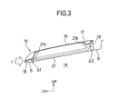
- FIG. 3 is a sectional view explaining a positional relationship between each of the radiator support upper 5 and the cowl 9 and each of the components 18 to 21 of the hood inner panel 17 with the engine room 1A being closed by the hood 15.
- the hood framework 21 is formed while protruded onto the side of the engine room 1A further than each of the front portion 18 and the rear portion 19 of the hood inner panel 17.
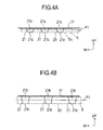
- the hood frameworks 21 are disposed between the radiator support upper 5 and the cowl 9 such that a front end-face 21a of each hood framework 21 and a rear end-face 21b thereof face the radiator support upper 5 and the cowl 9, respectively.
- a lower-side side-face 21c of each hood framework 21 is aligned with lower-side side-faces 5c and 9c of the radiator support upper 5 and the cowl 9, all the front end-faces 21a face the radiator support upper 5, and all the rear end-faces 21b face the cowl 9, however, the lower-side side-face 21c of each hood framework 21 may be offset to a position shown by two-dot chain lines P1 in FIGS.
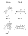
- the vehicle 1 Since the vehicle 1 has the above front-part structure, when the crash load is applied to the vehicle front part due to the front crash of the vehicle 1, as shown by an arrow F in FIG. 3 , the crash load is transmitted onto the side of the cabin 1B (vehicle rearward side) through the radiator support upper 5, each hood framework 21, and the cowl 9. Further, as shown in FIGS. 5A to 5D , in the vehicle 1, the number of supports of the radiator support upper 5 is increased from the conventional two-point support by the apron uppers 2 to the five-point support by three points with the hood frameworks 21. Therefore, as shown by support models of FIGS.
- a distance L' between support points of the radiator support upper 5 is shortened when compared with the conventional example L, so that bending moment applied to the radiator support upper 5 is decreased. Accordingly, rigidity of the radiator support upper 5 can be increased to thereby generate high reaction force in the radiator support upper 5.
- FIGS. 6 and 7 show the second embodiment according to the present invention.
- the same component as that in the first embodiment is denoted by the same reference numeral, and the description thereof will be omitted.
- hood frameworks 121 are provided so as to be suspended from a hood inner panel 117.
- a front portion 118, a rear portion 119, and side portions (not shown) of the hood inner panel 117 are integrally formed by the press working, and each hood framework 121 is joined to the hood inner panel 171 through hanging members 122 by the joining means such as the welding.
- each hood framework 121 is provided in the above embodiment, a degree of freedom is increased in design of each hood framework with no influence of the restriction in the press working, end faces 121a and 121b of each hood framework 121 can be projected toward the outside in the vehicle lengthwise direction. Accordingly, the gaps G1 and G2 (see FIG. 3 ) to be generated between the radiator support upper 5 and the cowl 9 in the first embodiment can be decreased. Therefore, the load transmission through each hood framework 121 becomes faster and more securely when in the front crash of the vehicle.
- hood frameworks 221 may be joined to a hood inner panel 217, in which a front portion 218, a rear portion 219, and side portions 220 are integrally formed, by the joining means such as the welding without using the hanging members 122.
- the same effect as that in the embodiment of FIGS. 6 and 7 is exerted.
- the reference numeral 221a denotes a front end-face
- the reference numeral 221b denotes a rear end-face.
- FIGS. 10 and 11 show the third embodiment according to the present invention.
- the same component as that in the first embodiment is denoted by the same reference numeral, and the description thereof will be omitted.
- rear end-faces 321b of hood frameworks 321 (only one side is shown in FIGS. 10 and 11 ) on the both sides in the vehicle width direction are disposed so as to face the suspension towers 11, each of which is of the upper vehicle framework member.
- the arrow F in FIG. 11 when in the front crash of the vehicle 1, the crash load is transmitted from the radiator support upper 5 to each suspension tower 11 through each hood framework 321.
- a load transmission member 322 may be provided between each suspension tower 11 and the cowl 9.
- each hood framework 321 may be joined to a hood inner panel 317, in which a front portion 318, a rear portion 319, and side portions 320 are integrally formed, by the joining means such as the welding.
- the front portion 318, the rear portion 319, the side portions 320, and the hood frameworks 321 may be integrally formed by the press working.
- FIGS. 12 and 13 show the fourth embodiment according to the present invention.
- the same component as that in the first embodiment is denoted by the same reference numeral, and the description thereof will be omitted.
- front-side pins (projections) 41 are provided on the radiator support upper 5, and a front-side hole (recess) 42 corresponding to each of the front-side pins 41 is provided on the front end-face 21a of each hood framework 21.
- Rear-side pins (projections) 43 are provided in the cowl 9, and a rear-side hole (recess) 44 corresponding to each of the rear-side pins 43 is provided on the rear end-face 21b of each hood framework 21.
- each hood framework 21 and the radiator support upper 5 are constrained with each other, each hood framework 21 and the cowl 9 are constrained with each other, and thus, the pins 41 and 43 and the holes 42 and 44 serve as the front-part constraint device (or means) and the rear-part constraint device (or means) of the present invention, respectively.
- a hook (retaining device) 45 is provided on each suspension tower 11.
- the hook 45 is engaged with the intermediate portion of each hood framework 21 to thereby couple each hood framework 21 and each suspension tower 11, and thus, the hook 45 serves as the joining device or means of the present invention.
- a connection point is formed between the intermediate portion of each hood framework 21 and each suspension tower 11 by the hook 45 to thereby increase the number of connection points between the vehicle 1 and the hood 15 (including each hood framework 21), so that, when in the front crash, the generation of the bending moment in the hood 15 and each hood framework 21 is to be suppressed, and thus, the crash load can efficiently be transmitted.
- Each of the front-side pins 41 may be provided on the front end-face 21a of each hood framework 21, and each of the rear-side pins 43 may be provided on the rear end-face 21b of each hood framework 21.
- the front-side holes 42 and the rear-side holes 44 may be provided on the radiator support upper 5 and the cowl 9, respectively.
- the rear-side pin 43 or the rear-side hole 44 may be provided on each suspension tower 11. The constraint of the members is not limited to a time at which the vehicle 1 crashes, but the members may be constrained during the engine room 1A is closed with the hood 15.
Landscapes
- Engineering & Computer Science (AREA)
- Chemical & Material Sciences (AREA)
- Combustion & Propulsion (AREA)
- Transportation (AREA)
- Mechanical Engineering (AREA)
- Body Structure For Vehicles (AREA)
- Superstructure Of Vehicle (AREA)
Description
- The present invention relates to a vehicle front-part structure.
- Conventionally, in some of the vehicle front-part structures, projection portions projected toward the outside in a vehicle width direction are provided on a radiator support sides that support both sides of a radiator, a front bumper reinforcement is attached through crash boxes onto vehicle front sides of the projection portions, and front side members are coupled onto vehicle rear sides of the projection portions. When in a slight degree of crash, a crash load is absorbed by the front bumper reinforcement and the crash boxes (Japanese Patent Application Laid-Open No.
2001-219869 DE 411 7 233 - In the above vehicle front-part structure, a radiator support upper that supports the upper portion of the radiator has the structure in which the crash load cannot sufficiently be received, and a member which receives the crash load does not exist in an upper portion of a vehicle front. Therefore, a distribution of the crash load acting on the vehicle front-part is biased in a lower portion of the vehicle front where the front bumper reinforcement and the like are located, and load uniformity is lost in the vehicle front in the front crash.
- In view of the foregoing, one object of the present invention is to provide a vehicle front-part structure which can receive the crash load in the crash even in the upper portion of the vehicle front.
- To attain the above object, according to one aspect of the present invention, there is provided a vehicle front-part structure comprising: a radiator support upper which extends in a vehicle width direction in a vehicle front; a vehicle upper frameworkmember which is coupled to an apron upper member provided on a side in the vehicle width direction and extending in a vehicle lengthwise direction, and which is located to rearward of the vehicle further than the radiator support upper; and a hood framework which constitutes a part of the hood framework member, the hood framework extending in the vehicle lengthwise direction, the hood framework being disposed between the radiator support upper and the vehicle upper framework member such that at least a part of a front end-face faces the radiator support upper and at least a part of a rear end-face faces the vehicle upper framework member.
- According to the above vehicle front-part structure, when in the front crash of the vehicle, the crash load is transmitted from the radiator support upper to the vehicle upper framework member through the hood framework. Then, the crash load is transmitted from the vehicle upper framework member to the apron upper member and is further transmitted to rearward of the vehicle. Therefore, the crash load applied to the vehicle upper portion can be efficiently transmitted to rearward of the vehicle. Furthermore, in the case that an engine room is opened by operating a hood, the hood framework moves to the upside of the vehicle along with the hood, so that the hood framework does not obstruct maintenance of the engine or the like. The whole of the front end-face of the hood framework may face the radiator support upper, and the whole of the rear end-face of the hood framework may face the vehicle upper framework member. In this case, the crash load can be transmitted more securely when compared with the mode in which a part of the front end-face faces the radiator support upper and a part of the rear end-face faces the vehicle upper framework member. In the concept of the end face of the hood framework according to the present invention, there is included not only the mode in which the material exists in all the end face (for example, the end face formed by a solid-core member) but also the mode in which the material does not exist in all the end face (for example, the end face made of H-shaped or C-shaped steel, and the end face formed by a hollow member such as a pipe). Accordingly, it is sufficient that the material facing the radiator support upper and the vehicle upper framework member exist in the hood framework.
- In one embodiment of the vehicle front-part structure according to the present invention, any member may be employed as the vehicle upper framework member that receives the crash load through the hood framework, as long as the member is coupled to the apron upper member with a predetermined strength. For example, the vehicle upper framework member may be a cowl extending in the vehicle width direction at a lower end of a wind shield, or may be a suspension tower. According to these embodiments, the crash load is transmitted from the radiator support upper to the cowl or the suspension tower through the hood framework, so that the crash load applied to the vehicle upper portion can be efficiently transmitted to rearward of the vehicle. The vehicle upper frameworkmember may be a dash panel which partitions the engine room and the cabin.
- In the case that the vehicle upper framework member is the suspension tower, a load transmission member may be provided between the suspension tower and a cowl extending in the vehicle width direction at a lower end of a wind shield. If the distance between the radiator support upper and the cowl is lengthened, a length of the member disposed between the radiator support upper and the cowl is increased, thereby raising the possibility that the bending moment is generated. If the bending moment is generated in the member, transmission efficiency of the crash load becomes worsened. According to the above embodiment, the crash load transmitted in the hood framework is transmitted to the cowl through the suspension tower and further thorough the load transmission member. Accordingly, the hood framework can be shortenedwhen compared with the case in which the hood framework is disposed between the radiator support upper and the cowl, so that the generation of the bending moment is suppressed to thereby efficiently transmit the crash load to rearward of the vehicle.
- In one embodiment according to the present invention, the vehicle front-part structuremay comprise a front-part constraint device which has: a projection which is provided on one of the front end-face of the hood framework and the radiator support upper; and a recess which is provided on the other of the front end-face of the hood framework and the radiator support upper, and the hood framework and the radiator support upper may be able to constrain each other by accommodating the projection in the recess. According to this embodiment, the hood framework and the radiator support upper are constrained by the front-part constraint device, so that occurrence, in which relative position displacement is generated between the hood framework and the radiator support upper and these members miss each other so as to obstruct the load transmission, can be avoided when in the front crash of the vehicle. With respect to timing at which the hood framework and the radiator support upper are constrained by the front-part constraint device, it is sufficient that these members are constrained at the time of crash, and those members may also be constrained during the time except for the crash.
- In one embodiment according to the present invention, the vehicle front-part structure may comprise a rear-part constraint device which has: a projection which is provided on one of the rear end-face of the hood framework and the vehicle upper framework member; and a recess which is provided on the other of the rear end-face of the hood framework and the vehicle upper framework member, and the hood framework and the vehicle upper framework member may be able to constrain each other by accommodating the projection in the recess. According to this embodiment, the hood framework and the vehicle upper framework member are constrained by the rear-part constraint device, so that occurrence, in which relative position displacement is generated between the hood framework and the vehicle upper frameworkmember and these members miss each other to obstruct the load transmission, can be avoided when in the front crash of the vehicle. With respect to timing at which the hood framework and the vehicle upper framework member are constrained by the rear-part constraint device, it is sufficient that these members are constrained at the time of crash, and these members may also be constrained during the time except for the crash.
- In one embodiment according to the present invention, the vehicle front-part structure may comprise a coupling device which has a retaining member provided on one of an intermediate portion of the hood framework and the suspension tower, and the hood framework and the suspension tower may be able to be coupled to each other by engaging the retaining member with the other of the intermediate portion of the hood framework and the suspension tower. According to this embodiment, a connection point is formed between the suspension tower and the intermediate portion of the hood framework by the retainingmember. Therefore, the number of connection points between the vehicle and the hood (including hood framework) is increased, so that the generation of the bending moment can be suppressed in the hood and the hood framework to thereby efficiently transmit the crash load in the front crash.
- As described above, according to the present invention, since the hood framework of which at least a part of the front end-face faces the radiator support upper while at least a part of the rear end-face faces the vehicle upper framework member is included, the crash load when in the crash can be received even in the upper portion of the vehicle front.
-
-
FIG. 1 is a view showing a vehicle front-part structure according to a first embodiment of the present invention while a hood is taken out; -
FIG. 2 is a view showing the vehicle front-part structure ofFIG. 1 ; -
FIG. 3 is a sectional view explaining a positional relationship between each of a radiator support upper and a cowl and each component of a hood inner panel while an engine room is closed with the hood; -
FIG. 4A is explanatory view showing a positional relationship between a front end-face of a hood framework and a radiator support upper; -
FIG. 4B is explanatory view showing a positional relationship between a rear end-face and a cowl; -
FIGS. 5A to 5D are explanatory views explaining a support structure of a radiator support upper in contrast with the conventional example, whereinFIG. 5A shows a front-part structure according to a conventional example,FIG. 5B shows a support model thereof,FIG. 5C shows the first embodiment according to the present invention andFIG. 5D shows a support model thereof; -
FIG. 6 is a view showing a vehicle front-part structure according to a second embodiment; -
FIG. 7 is a sectional view showing the front-part structure ofFIG. 6 ; -
FIG. 8 is a view showing a modification of the second embodiment; -
FIG. 9 is a sectional view showing the front-part structure ofFIG. 8 ; -
FIG. 10 is a view showing a vehicle front-part structure according to a third embodiment; -
FIG. 11 is a plan view showing the front-part structure ofFIG. 10 ; -
FIG. 12 is a view showing a vehicle front-part structure according to a fourth embodiment; and -
FIG. 13 is a sectional view showing the front-part structure ofFIG. 12 . -
FIGS. 1 and2 show a vehicle front-part structure according to the first embodiment of the present invention,FIG. 1 shows the vehicle front-part structure of which the hood is taken out, andFIG. 2 schematically shows the vehicle front-part structure in order to facilitate understanding the same. In these figures, the sign UP denotes an upward direction of the vehicle, the sign FR denotes a frontward direction of the vehicle, and the sign IN denotes an inward direction of the vehicle (the same holds in the following drawings). As shown inFIG. 1 , a vehicle 1 includes a pair of apronupper members radiator support apparatus 3 including a pair ofradiator support sides radiator support sides - The
radiator support sides 4 are connected to the apronupper members 2, respectively. Adash panel 8 which partitions anengine room 1A and acabin 1B of the vehicle 1 is provided to the rearward of the vehicle further than the radiator support upper 5, and both sides of thedash panel 8 in the vehicle width direction are joined to the apronupper members cowl 9 which extends in the vehicle width direction in a lower end 10a of awind shield 10 is provided forward of the vehicle further than thedash panel 8, and both sides of thecowl 9 are joined to the apronupper members cowl 9 and thedash panel 8 are arranged side by side in the vehicle lengthwise direction. Asuspension tower 11 which supports the suspension (not shown) is coupled to each apronupper member 2 in an integrally molding manner. - The vehicle 1 has a pair of
front side members upper members bumper reinforcement 13 is attached to the front ends of thefront side members crash boxes - As shown in
FIG. 2 , ahood 15 which opens and closes theengine room 1A is provided in the vehicle 1. Thehood 15 includes a hoodouter panel 16 on a surface side of the vehicle 1 and a hoodinner panel 17 which is combined with the hoodouter panel 16 to thereby form a framework member of thehood 15. The hoodinner panel 17 includes afront portion 18 which is located on the front side of the vehicle, arear portion 19 which is located to rearward of the vehicle, and a pair ofside portions front portion 18 and therear portion 19. Inside theside portions FIG. 2 ) in the vehicle lengthwise direction to couple thefront portion 18 and therear portion 19 with each other. In the embodiment ofFIG. 2 , thefront portion 18, therear portion 19, each of theside portions hood frameworks front portion 18, therear portion 19, each of theside portions 20, and each of thehood frameworks 21 form die-cut openings 22. However, the areas may not be subjected to die-cut and thus theopenings 22 may not be provided. -
FIG. 3 is a sectional view explaining a positional relationship between each of the radiator support upper 5 and thecowl 9 and each of thecomponents 18 to 21 of the hoodinner panel 17 with theengine room 1A being closed by thehood 15. As shown in this figure, thehood framework 21 is formed while protruded onto the side of theengine room 1A further than each of thefront portion 18 and therear portion 19 of the hoodinner panel 17. - As also shown in
FIGS. 4A and 4B , thehood frameworks 21 are disposed between the radiator support upper 5 and thecowl 9 such that a front end-face 21a of eachhood framework 21 and a rear end-face 21b thereof face the radiator support upper 5 and thecowl 9, respectively. In the first embodiment, a lower-side side-face 21c of eachhood framework 21 is aligned with lower-side side-faces 5c and 9c of the radiator support upper 5 and thecowl 9, all the front end-faces 21a face the radiator support upper 5, and all the rear end-faces 21b face thecowl 9, however, the lower-side side-face 21c of eachhood framework 21 may be offset to a position shown by two-dot chain lines P1 inFIGS. 4A and 4B in the upward direction of the vehicle. That is, it is sufficient that at least a part of the front end-face 21a and at least a part of the rear end-face 21b face the radiator support upper 5 and thecowl 9, respectively. In other words, when in the front crash of the vehicle 1, the radiator support upper 5 and the front end-face 21a of eachhood framework 21 abut on each other, and the rear end-face 21b of eachhood framework 21 and thecowl 9 abut on each other, thereby forming a transmission path of a crash load between the radiator support upper 5 and thecowl 9 through thehood frameworks 21. As shown inFIG. 3 , due to restriction of the press working, it is difficult to make the end faces 21a and 21b be projected toward the outside in the vehicle lengthwise direction, so that gaps G1 and G2 are formed between the front end-face 21a of eachhood framework 21 and the radiator support upper 5 and between the rear end-face 21b and thecowl 9, respectively. - Since the vehicle 1 has the above front-part structure, when the crash load is applied to the vehicle front part due to the front crash of the vehicle 1, as shown by an arrow F in
FIG. 3 , the crash load is transmitted onto the side of thecabin 1B (vehicle rearward side) through the radiator support upper 5, eachhood framework 21, and thecowl 9. Further, as shown inFIGS. 5A to 5D , in the vehicle 1, the number of supports of the radiator support upper 5 is increased from the conventional two-point support by theapron uppers 2 to the five-point support by three points with thehood frameworks 21. Therefore, as shown by support models ofFIGS. 5B and 5D , a distance L' between support points of the radiator support upper 5 is shortened when compared with the conventional example L, so that bending moment applied to the radiator support upper 5 is decreased. Accordingly, rigidity of the radiator support upper 5 can be increased to thereby generate high reaction force in the radiator support upper 5. - Further, as shown in
FIG. 1 , in the lower front of the vehicle, since the crash load is transmitted onto the side of thecabin 1B through thebumper reinforcement 13, thecrash boxes 14, and thefront side members 12, load uniformity is improved when in the front crash. -
FIGS. 6 and 7 show the second embodiment according to the present invention. In these figures, the same component as that in the first embodiment is denoted by the same reference numeral, and the description thereof will be omitted. In this embodiment,hood frameworks 121 are provided so as to be suspended from a hoodinner panel 117. Afront portion 118, arear portion 119, and side portions (not shown) of the hoodinner panel 117 are integrally formed by the press working, and eachhood framework 121 is joined to the hood inner panel 171 through hangingmembers 122 by the joining means such as the welding. Since eachhood framework 121 is provided in the above embodiment, a degree of freedom is increased in design of each hood framework with no influence of the restriction in the press working, end faces 121a and 121b of eachhood framework 121 can be projected toward the outside in the vehicle lengthwise direction. Accordingly, the gaps G1 and G2 (seeFIG. 3 ) to be generated between the radiator support upper 5 and thecowl 9 in the first embodiment can be decreased. Therefore, the load transmission through eachhood framework 121 becomes faster and more securely when in the front crash of the vehicle. In a modification of the second embodiment, as shown inFIGS. 8 and 9 ,hood frameworks 221 may be joined to a hoodinner panel 217, in which afront portion 218, arear portion 219, andside portions 220 are integrally formed, by the joining means such as the welding without using the hangingmembers 122. In this modification, the same effect as that in the embodiment ofFIGS. 6 and 7 is exerted. InFIGS. 8 and 9 , thereference numeral 221a denotes a front end-face, and thereference numeral 221b denotes a rear end-face. -
FIGS. 10 and 11 show the third embodiment according to the present invention. In these figures, the same component as that in the first embodiment is denoted by the same reference numeral, and the description thereof will be omitted. In this embodiment, rear end-faces 321b of hood frameworks 321 (only one side is shown inFIGS. 10 and 11 ) on the both sides in the vehicle width direction are disposed so as to face the suspension towers 11, each of which is of the upper vehicle framework member. In this case, as shown by the arrow F inFIG. 11 , when in the front crash of the vehicle 1, the crash load is transmitted from the radiator support upper 5 to eachsuspension tower 11 through eachhood framework 321. Further in this embodiment, aload transmission member 322 may be provided between eachsuspension tower 11 and thecowl 9. In this case, the crash load to be transmitted through eachhood framework 321 is transmitted to thecowl 9 through eachsuspension tower 11 and eachload transmission member 322. Accordingly, eachhood framework 321 can be shortened when compared with the case in which one hood framework is disposed between the radiator support upper 5 and thecowl 9. Therefore, generation of the bending moment in eachhood framework 321 can be suppressed to thereby efficiently transmit the crash load onto the side of thecabin 1B. In the embodiment ofFIG. 10 , eachhood framework 321 may be joined to a hoodinner panel 317, in which afront portion 318, arear portion 319, andside portions 320 are integrally formed, by the joining means such as the welding. However, thefront portion 318, therear portion 319, theside portions 320, and thehood frameworks 321 may be integrally formed by the press working. -
FIGS. 12 and 13 show the fourth embodiment according to the present invention. In these figures, the same component as that in the first embodiment is denoted by the same reference numeral, and the description thereof will be omitted. As shown inFIGS. 12 and 13 , in the fourth embodiment, front-side pins (projections) 41 are provided on the radiator support upper 5, and a front-side hole (recess) 42 corresponding to each of the front-side pins 41 is provided on the front end-face 21a of eachhood framework 21. Rear-side pins (projections) 43 are provided in thecowl 9, and a rear-side hole (recess) 44 corresponding to each of the rear-side pins 43 is provided on the rear end-face 21b of eachhood framework 21. When in the front crash of the vehicle 1, a relative distance between the front end-face 21a of eachhood framework 21 and the radiator support upper 5 and a relative distance between the rear end-face 21b of eachhood framework 21 and thecowl 9 are decreased, and the front-side pins 41 and the rear-side pins 43 are received by the front-side holes 42 and the rear-side holes 44, respectively. Therefore, eachhood framework 21 and the radiator support upper 5 are constrained with each other, eachhood framework 21 and thecowl 9 are constrained with each other, and thus, thepins holes - A hook (retaining device) 45 is provided on each
suspension tower 11. When theengine room 1A is closed with thehood 15, thehook 45 is engaged with the intermediate portion of eachhood framework 21 to thereby couple eachhood framework 21 and eachsuspension tower 11, and thus, thehook 45 serves as the joining device or means of the present invention. - As described above, when in the front crash of the vehicle 1, the relative position displacement between each
hood framework 21 and the radiator support upper 5 and the relative position displacement between eachhood framework 21 and thecowl 9 are prevented, respectively, so that the state in which these members miss one another so as to obstruct the load transmission can be avoided. A connection point is formed between the intermediate portion of eachhood framework 21 and eachsuspension tower 11 by thehook 45 to thereby increase the number of connection points between the vehicle 1 and the hood 15 (including each hood framework 21), so that, when in the front crash, the generation of the bending moment in thehood 15 and eachhood framework 21 is to be suppressed, and thus, the crash load can efficiently be transmitted. - Each of the front-
side pins 41 may be provided on the front end-face 21a of eachhood framework 21, and each of the rear-side pins 43 may be provided on the rear end-face 21b of eachhood framework 21. Correspondingly, the front-side holes 42 and the rear-side holes 44 may be provided on the radiator support upper 5 and thecowl 9, respectively. In the embodiment ofFIG. 10 (the third embodiment), the rear-side pin 43 or the rear-side hole 44 may be provided on eachsuspension tower 11. The constraint of the members is not limited to a time at which the vehicle 1 crashes, but the members may be constrained during theengine room 1A is closed with thehood 15.
Claims (10)
- A vehicle front-part structure comprising:a radiator support upper (5) which extends in a vehicle width direction in a vehicle front;a vehicle upper framework member (9) which is coupled to an apron upper member (2) provided on a side in the vehicle width direction and extending in a vehicle lengthwise direction, and which is located to rearward of the vehicle further than the radiator support upper; anda hood framework (22) which constitutes a part of the hood framework member, the hood framework extending in the vehicle lengthwise direction characterised by the hood framework being disposed between the radiator support upper and the vehicle upper framework member such that at least a part of a front end-face faces the radiator support upper (5) and at least a part of a rear end-face faces the vehicle upper framework member (9).
- The vehicle front-part structure according to claim 1, wherein the vehicle upper framework member is a cowl extending in the vehicle width direction at a lower end of a wind shield.
- The vehicle front-part structure according to claim 1, wherein the vehicle upper framework member is a suspension tower.
- The vehicle front-part structure according to claim 3, wherein a load transmission member is provided between the suspension tower and a cowl extending in the vehicle width direction at a lower end of a wind shield.
- The vehicle front-part structure according to any one of claims 1 to 3, comprising a front-part constraint device which has:a projection which is provided on one of the front end-face of the hood framework and the radiator support upper; anda recess which is provided on the other of the front end-face of the hood framework and the radiator support upper,wherein the hood framework and the radiator support upper are able to constrain each other by accommodating the projection in the recess.
- The vehicle front-part structure according to any one of claims 1 to 3, comprising a rear-part constraint device which has:a projection which is provided on one of the rear end-face of the hood framework and the vehicle upper framework member; anda recess which is provided on the other of the rear end-face of the hood framework and the vehicle upper framework member,wherein the hood framework and the vehicle upper framework member are able to constrain each other by accommodating the projection in the recess.
- The vehicle front-part structure according to any one of claims 1 to 3, comprising a coupling device which has a retaining member provided on one of an intermediate portion of the hood framework and the suspension tower, wherein the hood framework and the suspension tower are able to be coupled to each other by engaging the retaining member with the other of the intermediate portion of the hood framework and the suspension tower.
- The vehicle front-part structure according to claim 1, wherein the vehicle upper structure is a member which is extending in the vehicle width direction and is coupled to both aprons.
- The vehicle front-part structure according to claim 1, wherein the hood framework comprises a member which is extending along the vehicle lengthwise direction.
- The vehicle front-part structure according to claim 1, wherein the part of the rear end-face of the hood framework faces the vehicle upper framework member at a position remote from the apron upper member, which is provided on an end in the width direction.
Applications Claiming Priority (2)
| Application Number | Priority Date | Filing Date | Title |
|---|---|---|---|
| JP2005029674A JP4270135B2 (en) | 2005-02-04 | 2005-02-04 | Vehicle front structure |
| PCT/JP2006/302103 WO2006082991A1 (en) | 2005-02-04 | 2006-02-01 | Vehicle front-part structure |
Publications (2)
| Publication Number | Publication Date |
|---|---|
| EP1846279A1 EP1846279A1 (en) | 2007-10-24 |
| EP1846279B1 true EP1846279B1 (en) | 2009-12-09 |
Family
ID=36441997
Family Applications (1)
| Application Number | Title | Priority Date | Filing Date |
|---|---|---|---|
| EP06713246A Expired - Lifetime EP1846279B1 (en) | 2005-02-04 | 2006-02-01 | Vehicle front-part structure |
Country Status (5)
| Country | Link |
|---|---|
| EP (1) | EP1846279B1 (en) |
| JP (1) | JP4270135B2 (en) |
| CN (1) | CN100537327C (en) |
| DE (1) | DE602006010973D1 (en) |
| WO (1) | WO2006082991A1 (en) |
Families Citing this family (3)
| Publication number | Priority date | Publication date | Assignee | Title |
|---|---|---|---|---|
| JP5200606B2 (en) * | 2008-03-21 | 2013-06-05 | トヨタ自動車株式会社 | Body front structure |
| JP5092849B2 (en) * | 2008-04-03 | 2012-12-05 | 日産自動車株式会社 | Opening and closing structure of vehicle |
| CN106064643B (en) * | 2016-06-01 | 2018-09-11 | 北京长城华冠汽车科技股份有限公司 | On a kind of front on frame and the application front frame automobile |
Family Cites Families (7)
| Publication number | Priority date | Publication date | Assignee | Title |
|---|---|---|---|---|
| US3709316A (en) * | 1971-10-26 | 1973-01-09 | Ford Motor Co | Cam action safety hood |
| JPS58211974A (en) * | 1982-06-02 | 1983-12-09 | Nissan Motor Co Ltd | Hood stopper structure |
| DE4117233A1 (en) * | 1990-06-08 | 1991-12-12 | Volkswagen Ag | Safety latch for bonnet of motor vehicle - has retainer on upper end of housing of suspension spring strut |
| EP0561822B1 (en) * | 1990-12-20 | 1994-08-10 | Audi Ag | Bearer joint for vehicle bodywork, especially longitudinal bearer joint, and process for replacing an aluminium bearer |
| JP2002544057A (en) * | 1999-05-17 | 2002-12-24 | エドシャ・アクチェンゲゼルシャフト | Front bonnet structure |
| JP2001219869A (en) | 2000-02-09 | 2001-08-14 | Toyota Motor Corp | Front-end module |
| FR2813848B1 (en) * | 2000-09-13 | 2003-02-14 | Peguform France | MOTOR VEHICLE COMPRISING BODY PARTS ASSOCIATED WITH A REDUCED GAME |
-
2005
- 2005-02-04 JP JP2005029674A patent/JP4270135B2/en not_active Expired - Fee Related
-
2006
- 2006-02-01 EP EP06713246A patent/EP1846279B1/en not_active Expired - Lifetime
- 2006-02-01 DE DE602006010973T patent/DE602006010973D1/en not_active Expired - Lifetime
- 2006-02-01 WO PCT/JP2006/302103 patent/WO2006082991A1/en not_active Ceased
- 2006-02-01 CN CNB2006800035767A patent/CN100537327C/en not_active Expired - Fee Related
Also Published As
| Publication number | Publication date |
|---|---|
| JP2006213244A (en) | 2006-08-17 |
| JP4270135B2 (en) | 2009-05-27 |
| WO2006082991A1 (en) | 2006-08-10 |
| CN101111424A (en) | 2008-01-23 |
| DE602006010973D1 (en) | 2010-01-21 |
| EP1846279A1 (en) | 2007-10-24 |
| CN100537327C (en) | 2009-09-09 |
Similar Documents
| Publication | Publication Date | Title |
|---|---|---|
| US10421500B2 (en) | Vehicle framework structure | |
| CN108791522B (en) | vehicle substructure | |
| US9027987B2 (en) | Vehicle hood structure | |
| US20130249245A1 (en) | Front vehicle body structure | |
| US20170113729A1 (en) | Vehicle floor portion structure | |
| JP6557290B2 (en) | Body front structure | |
| CN110816675B (en) | Vehicle front structure | |
| JP6584457B2 (en) | Body front structure | |
| CN103998328B (en) | Vehicle front body structure | |
| US8096611B2 (en) | Vehicle front-part structure | |
| JP5007580B2 (en) | Body front structure | |
| JP6020530B2 (en) | Vehicle skeleton structure | |
| US12612113B2 (en) | Vehicle rear component | |
| CN112298366A (en) | Cross member structure of vehicle body | |
| JP6136845B2 (en) | Vehicle front structure | |
| JP6579131B2 (en) | Front body structure of the vehicle | |
| WO2006082991A1 (en) | Vehicle front-part structure | |
| JP2009041760A (en) | Vibration control device | |
| JP5234324B2 (en) | Vehicle body structure | |
| CN211731585U (en) | Front wall plate reinforcing structure | |
| KR101762267B1 (en) | Structure of front body and manufacturing method threrof | |
| CN115107875B (en) | Front body structure | |
| KR100422836B1 (en) | Roof reinforcing assembly | |
| JP2010120402A (en) | Front body structure of automobile | |
| JP6787284B2 (en) | Vehicle front structure |
Legal Events
| Date | Code | Title | Description |
|---|---|---|---|
| PUAI | Public reference made under article 153(3) epc to a published international application that has entered the european phase |
Free format text: ORIGINAL CODE: 0009012 |
|
| 17P | Request for examination filed |
Effective date: 20070823 |
|
| AK | Designated contracting states |
Kind code of ref document: A1 Designated state(s): DE FR GB IT |
|
| DAX | Request for extension of the european patent (deleted) | ||
| RBV | Designated contracting states (corrected) |
Designated state(s): DE FR GB IT |
|
| 17Q | First examination report despatched |
Effective date: 20080915 |
|
| GRAP | Despatch of communication of intention to grant a patent |
Free format text: ORIGINAL CODE: EPIDOSNIGR1 |
|
| GRAS | Grant fee paid |
Free format text: ORIGINAL CODE: EPIDOSNIGR3 |
|
| GRAA | (expected) grant |
Free format text: ORIGINAL CODE: 0009210 |
|
| AK | Designated contracting states |
Kind code of ref document: B1 Designated state(s): DE FR GB IT |
|
| REG | Reference to a national code |
Ref country code: GB Ref legal event code: FG4D |
|
| REF | Corresponds to: |
Ref document number: 602006010973 Country of ref document: DE Date of ref document: 20100121 Kind code of ref document: P |
|
| PLBE | No opposition filed within time limit |
Free format text: ORIGINAL CODE: 0009261 |
|
| STAA | Information on the status of an ep patent application or granted ep patent |
Free format text: STATUS: NO OPPOSITION FILED WITHIN TIME LIMIT |
|
| 26N | No opposition filed |
Effective date: 20100910 |
|
| REG | Reference to a national code |
Ref country code: GB Ref legal event code: 746 Effective date: 20121112 |
|
| REG | Reference to a national code |
Ref country code: DE Ref legal event code: R084 Ref document number: 602006010973 Country of ref document: DE Effective date: 20121115 |
|
| PGFP | Annual fee paid to national office [announced via postgrant information from national office to epo] |
Ref country code: DE Payment date: 20140129 Year of fee payment: 9 |
|
| PGFP | Annual fee paid to national office [announced via postgrant information from national office to epo] |
Ref country code: IT Payment date: 20140220 Year of fee payment: 9 Ref country code: FR Payment date: 20140211 Year of fee payment: 9 |
|
| PGFP | Annual fee paid to national office [announced via postgrant information from national office to epo] |
Ref country code: GB Payment date: 20140129 Year of fee payment: 9 |
|
| REG | Reference to a national code |
Ref country code: DE Ref legal event code: R119 Ref document number: 602006010973 Country of ref document: DE |
|
| GBPC | Gb: european patent ceased through non-payment of renewal fee |
Effective date: 20150201 |
|
| REG | Reference to a national code |
Ref country code: FR Ref legal event code: ST Effective date: 20151030 |
|
| PG25 | Lapsed in a contracting state [announced via postgrant information from national office to epo] |
Ref country code: IT Free format text: LAPSE BECAUSE OF NON-PAYMENT OF DUE FEES Effective date: 20150201 |
|
| PG25 | Lapsed in a contracting state [announced via postgrant information from national office to epo] |
Ref country code: DE Free format text: LAPSE BECAUSE OF NON-PAYMENT OF DUE FEES Effective date: 20150901 Ref country code: GB Free format text: LAPSE BECAUSE OF NON-PAYMENT OF DUE FEES Effective date: 20150201 |
|
| PG25 | Lapsed in a contracting state [announced via postgrant information from national office to epo] |
Ref country code: FR Free format text: LAPSE BECAUSE OF NON-PAYMENT OF DUE FEES Effective date: 20150302 |