EP1845552A1 - Transportation system and transportation method - Google Patents
Transportation system and transportation method Download PDFInfo
- Publication number
- EP1845552A1 EP1845552A1 EP07007643A EP07007643A EP1845552A1 EP 1845552 A1 EP1845552 A1 EP 1845552A1 EP 07007643 A EP07007643 A EP 07007643A EP 07007643 A EP07007643 A EP 07007643A EP 1845552 A1 EP1845552 A1 EP 1845552A1
- Authority
- EP
- European Patent Office
- Prior art keywords
- transportation system
- transportation
- small article
- conveyor
- container
- Prior art date
- Legal status (The legal status is an assumption and is not a legal conclusion. Google has not performed a legal analysis and makes no representation as to the accuracy of the status listed.)
- Granted
Links
Images

Classifications
-
- B—PERFORMING OPERATIONS; TRANSPORTING
- B65—CONVEYING; PACKING; STORING; HANDLING THIN OR FILAMENTARY MATERIAL
- B65G—TRANSPORT OR STORAGE DEVICES, e.g. CONVEYORS FOR LOADING OR TIPPING, SHOP CONVEYOR SYSTEMS OR PNEUMATIC TUBE CONVEYORS
- B65G47/00—Article or material-handling devices associated with conveyors; Methods employing such devices
- B65G47/52—Devices for transferring articles or materials between conveyors i.e. discharging or feeding devices
-
- H—ELECTRICITY
- H01—ELECTRIC ELEMENTS
- H01L—SEMICONDUCTOR DEVICES NOT COVERED BY CLASS H10
- H01L21/00—Processes or apparatus adapted for the manufacture or treatment of semiconductor or solid state devices or of parts thereof
- H01L21/67—Apparatus specially adapted for handling semiconductor or electric solid state devices during manufacture or treatment thereof; Apparatus specially adapted for handling wafers during manufacture or treatment of semiconductor or electric solid state devices or components ; Apparatus not specifically provided for elsewhere
- H01L21/67005—Apparatus not specifically provided for elsewhere
- H01L21/67242—Apparatus for monitoring, sorting or marking
- H01L21/67276—Production flow monitoring, e.g. for increasing throughput
-
- H—ELECTRICITY
- H01—ELECTRIC ELEMENTS
- H01L—SEMICONDUCTOR DEVICES NOT COVERED BY CLASS H10
- H01L21/00—Processes or apparatus adapted for the manufacture or treatment of semiconductor or solid state devices or of parts thereof
- H01L21/67—Apparatus specially adapted for handling semiconductor or electric solid state devices during manufacture or treatment thereof; Apparatus specially adapted for handling wafers during manufacture or treatment of semiconductor or electric solid state devices or components ; Apparatus not specifically provided for elsewhere
- H01L21/677—Apparatus specially adapted for handling semiconductor or electric solid state devices during manufacture or treatment thereof; Apparatus specially adapted for handling wafers during manufacture or treatment of semiconductor or electric solid state devices or components ; Apparatus not specifically provided for elsewhere for conveying, e.g. between different workstations
- H01L21/67703—Apparatus specially adapted for handling semiconductor or electric solid state devices during manufacture or treatment thereof; Apparatus specially adapted for handling wafers during manufacture or treatment of semiconductor or electric solid state devices or components ; Apparatus not specifically provided for elsewhere for conveying, e.g. between different workstations between different workstations
- H01L21/6773—Conveying cassettes, containers or carriers
-
- H—ELECTRICITY
- H01—ELECTRIC ELEMENTS
- H01L—SEMICONDUCTOR DEVICES NOT COVERED BY CLASS H10
- H01L21/00—Processes or apparatus adapted for the manufacture or treatment of semiconductor or solid state devices or of parts thereof
- H01L21/67—Apparatus specially adapted for handling semiconductor or electric solid state devices during manufacture or treatment thereof; Apparatus specially adapted for handling wafers during manufacture or treatment of semiconductor or electric solid state devices or components ; Apparatus not specifically provided for elsewhere
- H01L21/677—Apparatus specially adapted for handling semiconductor or electric solid state devices during manufacture or treatment thereof; Apparatus specially adapted for handling wafers during manufacture or treatment of semiconductor or electric solid state devices or components ; Apparatus not specifically provided for elsewhere for conveying, e.g. between different workstations
- H01L21/67703—Apparatus specially adapted for handling semiconductor or electric solid state devices during manufacture or treatment thereof; Apparatus specially adapted for handling wafers during manufacture or treatment of semiconductor or electric solid state devices or components ; Apparatus not specifically provided for elsewhere for conveying, e.g. between different workstations between different workstations
- H01L21/67733—Overhead conveying
-
- H—ELECTRICITY
- H01—ELECTRIC ELEMENTS
- H01L—SEMICONDUCTOR DEVICES NOT COVERED BY CLASS H10
- H01L21/00—Processes or apparatus adapted for the manufacture or treatment of semiconductor or solid state devices or of parts thereof
- H01L21/67—Apparatus specially adapted for handling semiconductor or electric solid state devices during manufacture or treatment thereof; Apparatus specially adapted for handling wafers during manufacture or treatment of semiconductor or electric solid state devices or components ; Apparatus not specifically provided for elsewhere
- H01L21/677—Apparatus specially adapted for handling semiconductor or electric solid state devices during manufacture or treatment thereof; Apparatus specially adapted for handling wafers during manufacture or treatment of semiconductor or electric solid state devices or components ; Apparatus not specifically provided for elsewhere for conveying, e.g. between different workstations
- H01L21/67703—Apparatus specially adapted for handling semiconductor or electric solid state devices during manufacture or treatment thereof; Apparatus specially adapted for handling wafers during manufacture or treatment of semiconductor or electric solid state devices or components ; Apparatus not specifically provided for elsewhere for conveying, e.g. between different workstations between different workstations
- H01L21/67736—Loading to or unloading from a conveyor
-
- Y—GENERAL TAGGING OF NEW TECHNOLOGICAL DEVELOPMENTS; GENERAL TAGGING OF CROSS-SECTIONAL TECHNOLOGIES SPANNING OVER SEVERAL SECTIONS OF THE IPC; TECHNICAL SUBJECTS COVERED BY FORMER USPC CROSS-REFERENCE ART COLLECTIONS [XRACs] AND DIGESTS
- Y10—TECHNICAL SUBJECTS COVERED BY FORMER USPC
- Y10S—TECHNICAL SUBJECTS COVERED BY FORMER USPC CROSS-REFERENCE ART COLLECTIONS [XRACs] AND DIGESTS
- Y10S414/00—Material or article handling
- Y10S414/135—Associated with semiconductor wafer handling
- Y10S414/137—Associated with semiconductor wafer handling including means for charging or discharging wafer cassette
Definitions
- the present invention relates a system for transporting small articles such as reticle cassettes using a transportation system for large articles such as semiconductor cassettes (FOUPs).
- FOUPs semiconductor cassettes
- the reticle is a mask for light exposure.
- the reticle is transported between a reticle magazine and an exposure apparatus.
- the reticle needs to be transported, e.g., manually. This is because, in comparison with the transportation system for FOUPs, in the transportation system for reticle cassettes, the transportation amount is small, the travel route is limited in a bay or the like, and long distance transportation is not possible.
- An object of the present invention is to transport small articles between a transportation system for large articles and a transportation system for small articles. Another object of the present invention is to make it possible to transfer a small article between a container and a conveyor through a relatively small opening without changing the orientation of the small article. Still another object of the present invention is to reduce the wait time of a transportation system for small articles.
- a system for transporting a small article between a first transportation system for transportation of small articles and a second transportation system for transportation of large articles comprises a container which can store the small article, and which can be transported by the second transportation system, the container having an opening for allowing the small article to move into and out of the container; a conveyor for transporting the small article between the first transportation system and the second transportation system; a station capable of transferring the container from/to the second transportation system; and transfer means for transferring the small article between the container at the station and the conveyor.
- the transfer means comprises elevation means for lifting up the small article and moving means for moving the lifted up small article between the container at the station and the conveyor through the opening.
- a transportation method for transporting a small article between a first transportation system for transportation of small articles and a second transportation system for transportation of large articles comprises the steps of: providing a conveyor for transporting the small article between the first transportation system and the second transportation system; providing a station for supporting a container which can be transported by the second transportation system, between the second transportation system and the conveyor; and providing transfer means for transferring the small article between the container at the station and the conveyor.
- the container can store the small article, and has an opening for allowing the small article to move into and out of the container;
- the transfer means comprises elevation means and moving means;
- the conveyor transports the small article between the first transportation system and the transfer means;
- the transfer means lifts up the small article; and the lifted up small article is transferred between the container at the station and the conveyor through the opening by the moving means.
- the opening is provided on a side surface of the container and the transfer means comprises a cart guided along a rail as the moving means, and an elevation frame as the elevation means.
- the conveyor is used as a buffer for the small article as well.
- the small article is transferred by the transfer means between the container and the conveyor through the opening of the container.
- the small article is lifted up. Therefore, in comparison with the case of pushing the small article using a pusher or the like, the article can be transferred smoothly.
- the small article can be transferred between the transfer means and the transportation system for small articles.
- the small article is placed in the container, and the container can be transported by the transportation system for large articles (second transportation system). Therefore, the transportation system for large articles can be utilized for transportation in segments where the article cannot be transported by the transportation system for small articles (first transportation system).
- the container has an opening on its side surface
- the transfer means comprises a cart guided along a rail, and an elevation frame.
- the small article is lifted up by the elevation frame.
- the small article moves between the container and the conveyor through the opening on the side surface of the container. Therefore, in comparison with the case of using a SCARA arm or the like, the small article can be transferred through the relatively small opening.
- the cart is used for moving the small article, in comparison with the case of using a slide fork or the like, the small article can be accurately placed in the container, or accurately placed on the conveyor.
- the conveyor can be used as a buffer of the small article as well, the wait time of the transportation system for small articles is reduced. For example, if the small article is transported by the transportation system for small articles, the small article can be stored in the buffer, and if there is any delay in the transportation system for small articles, the small article can wait in the buffer.
- FIG. 1 to 7 shows a transportation system 2 according to an embodiment.
- a reference numeral 4 denotes a conveyor.
- the conveyor 4 includes three kinds of units, i.e., a reticle side station 6, a conveyor unit 7, and a FOUP side unit 8. These units 6 to 8 are operated independently, and each of the units 6 to 8 functions as a buffer for storing reticle cassettes (articles) 18 one by one.
- a station 10 is connected to the FOUP side unit 8 of the conveyor 4.
- a reference numeral 12 denotes a groove formed in the station 10.
- a rail vehicle 14 travels along the groove 12.
- the rail vehicle 14 includes a cart 15 and a lifter 16.
- the rail vehicle 14 is guided along a travel rail 34 shown in FIG. 4.
- the rail vehicle 14 may be equipped with a motor to travel by itself. Alternatively, the rail vehicle 14 may be towed by a chain or the like.
- the lifter 16 is elevated or lowered by an elevation arm 17. In the embodiment, the elevation arm 17 is provided at the center in the travel direction of the lifter 16. Alternatively, the elevation arm 17 may be provided near the conveyor 4 opposite to the station 10.
- the reticle cassette 18 is a cassette storing a reticle for exposure of semiconductors or liquid crystal display panels.
- the small article as the target of transportation is not limited to the reticle cassette, and may be a cassette as a target of spattering.
- a flange 20 is provided at an upper portion of the reticle cassette 18 for allowing an overhead traveling vehicle 42 shown in FIG. 4 to chuck the flange 20 for transportation of the reticle cassette 18.
- a reference numeral 22 denotes a dummy FOUP.
- the dummy FOUP 22 is placed on the station 10.
- An overhead traveling vehicle 52 shown in FIG. 4 chucks a flange 24 of the dummy FOUP 22 for transportation of the dummy FOUP 22.
- the outer shape of the dummy FOUP 22 is similar to that of a normal FOUP for transportation of semiconductor wafers.
- the normal FOUP for transportation of semiconductor wafers is an example of a large article as stated in the claims, and the dummy FOUP 22 is an example of a container containing a small article for transportation.
- the respective conveyor units 6 to 8 and the rail vehicle 14 of the transportation system 2 are controlled by a control unit 26.
- the control unit 26 communicates with an upper level controller 30 through a communication unit 28.
- the upper level controller 30 communicates with a reticle transportation vehicle controller 32 as a controller in a first transportation system and a FOUP transportation vehicle controller 33 as a controller in a second transportation system.
- the control unit 26 communicates with the controllers 32, 33 through the communication unit 28 and the upper level controller 30.
- communication units for communication with the overhead traveling vehicles 42, 52 shown in FIG. 4 may be provided in the reticle side station 6 and the station 10 for allowing the overhead traveling vehicles 42, 52 to directly communicate with the stations 6, 10.
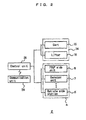
- FIG. 2 shows a control system of the transportation system 2.
- the rail vehicle 14 includes the cart 15 and the lifter 16.
- the conveyor 4 includes the FOUP side unit 8 and a plurality of the conveyor units 7, and the reticle side station 6.
- the units 7, 8, and the station 6 are operated independently to function as an accumulation conveyor.
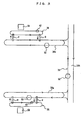
- FIG. 3 shows the usage environment of the transportation system 2 according to the embodiment.
- a reference numeral 38 denotes a FOUP transportation system.
- the FOUP transportation system 38 is an example of a second transportation system for transportation of large articles.
- the FOUP transportation system 38 uses the overhead traveling vehicle 52 shown in FIG. 4, and includes a plurality of intra-bay routes 38a, and an inter-bay route 38b connecting the intra-bay routes 38a.
- the overhead traveling vehicle 52 travels in a direction indicated by an arrow in FIG. 3.
- the reticle transportation system 36 is a system for transporting a reticle cassette storing a reticle between a reticle magazine 39 and an exposure apparatus (not shown) in one bay.
- the reticle transportation system 36 is an example of the first transportation system for transporting small articles in the claims.
- the reticle transportation system 36 uses the overhead traveling vehicle 42 shown in FIG. 4.
- the overhead traveling vehicle 42 travels around the bay in a direction indicated by an arrow in FIG. 3, and transports the reticle cassette between the different bays using the transportation system 2 and the FOUP transportation system 38.
- at least a pair of the transportation systems 2 according to the embodiment are provided between the transportation systems 36, 38, and the transportation systems 2 have different directions of transporting the reticle cassettes.
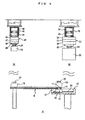
- reference numerals 40, 50 denote travel rails.
- the travel rails 40, 50 are supported by support columns 41,51, e.g., in a clean room of a building.
- the overhead traveling vehicle 42 for reticle transportation includes a travel cart 44, a power receiving cart 45 for receiving electricity from the travel rail 40, and a lateral feed unit 46 for laterally feeding a ⁇ drive 47 and portion below the ⁇ drive 47 relative to the travel rail 40.
- the ⁇ drive 47 rotates an elevation drive unit 48 in a horizontal plane and controls the orientation of the reticle cassette 18.
- the elevation drive unit 48 elevates/lowers the elevation frame 49 chucking the reticle cassette 18 for transferring the reticle cassette 18 to/from the exposure apparatus, the station of the reticle magazine, or the reticle side station 6.
- the lateral feed unit 46 and the ⁇ drive 47 may not be provided.
- a travel cart 54 travels inside the travel rail 50.
- a power receiving cart 55 receives electricity, and a lateral feed unit 56 laterally feeds a ⁇ drive 57, and portion below the ⁇ drive 57 relative to the travel rail 50.
- the ⁇ drive 57 rotates an elevation drive unit 58 and portion below the elevation unit 58 in a horizontal plane.
- An elevation frame 59 chucks the dummy FOUP or the normal FOUP storing a dummy FOUP 22 and a semiconductor cassette at the flange 24.
- the elevation frame 59 is elevated/lowered by the elevation drive unit 58. In this manner, the dummy FOUP 22 is transferred to/from the station 10.
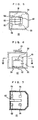
- FIGS. 5 to 7 show a shape of the dummy FOUP 22.
- the shape of the dummy FOUP 22 is similar to that of the FOUP for transportation of semiconductor wafers.
- the dummy FOUP 22 has an opening 60 on a side surface, and has a hole 62 at the bottom.
- the reticle cassettes 18 are placed on tables 64, e.g. provided at four positions in the dummy FOUP 22. Gaps between the tables 64 is larger than the width of the lifter.
- the elevation arm 17 is elevated to lift up the lifter 16, thereby lifting up the reticle cassette 18 on the conveyor or in the dummy FOUP 22.
- the elevation arm 17 passes through the hole 62, and the lifter and the reticle cassette 18 pass through the opening 60 to move the reticle cassette 18 toward the inside or outside of the dummy FOUP 22.
- the elevation arm 17 in FIG. 4 is positioned at the center in the traveling direction of the lifter 16. Therefore, the dummy FOUP 22 needs to have the hole 62. However, if the elevation arm 17 is provided on a side of the lifter 16 near the conveyor 4, the hole 62 is not required, or the length of the hole 62 can be reduced.
- the rail vehicle 14 is provided below the conveyor 4. Alternatively, the travel rail 34 and the rail vehicle 14 may be provided above the conveyor 4. In this case, the flange 20 is chucked and lifted up, and the reticle cassette 18 is laterally moved toward the inside or outside of the dummy FOUP 22.
- a SCARA arm or a slide fork may be used to transfer the reticle cassette 18.
- the SCARA arm or the slide fork is attached to a lifter (not shown), the flange 20 is chucked by the SCARA arm or the slide fork and the reticle cassette 18 is moved laterally.
- the opening 60 of the dummy FOUP 22 needs to be large so that the arm can pass through the opening 60.
- the position of transferring the reticle cassette 18 tends to be inaccurate in comparison with the case of using the rail vehicle 14 or the SCARA arm.
- the dummy FOUP 22 storing the reticle cassette is unloaded from the overhead traveling vehicle 52 to the station 10. Then, the rail vehicle 14 travels to the right side in FIG. 4, the elevation arm 17 passes through the hole 62 of the bottom surface of the dummy FOUP 22, the lifter 16 passes through the opening 60, and the lifter 16 moves into the dummy FOUP 22. By lifting up the lifter 16, the reticle cassette 18 is transferred from the table 64 to the lifter 16. Thereafter, the rail vehicle 14 moves backwardly, and the lifter 16 is lowered.
- the reticle cassette 18 is transferred to the FOUP side unit 8 of the conveyor 4.
- the conveyor 4 includes a plurality of units 7.
- the units 7 are used as the buffers.
- the cassette 18 waits on the conveyor 4 until the cassette 18 is transferred to the overhead traveling vehicle 42 of the reticle transportation system 36.
- the units 7 of the conveyor 4 is used as the buffers so that the reticle cassette 18 can wait on the conveyor 4 until an empty dummy FOUP 22 arrives at the station 10.
- the lifter 16 is lifted up to pick up the reticle cassette 18.
- the rail vehicles 14 travels to the right side in FIG. 4, and the lifter 16 is lowered to unload the reticle cassette 18 onto the table 64 of the dummy FOUP 22.
- the reticle cassette 18 is shown as an example of the small article, and the FOUP is shown as an example of the large article.
- the present invention is not limited in this respect.
- the types of the reticle transportation system 36 and the FOUP transportation system 38 can be selected arbitrarily. Instead of using the system of overhead traveling vehicles, a system of rail vehicles, a system of long-distance conveyors, or a system of stacker cranes may be used.
Abstract
Description
- The present invention relates a system for transporting small articles such as reticle cassettes using a transportation system for large articles such as semiconductor cassettes (FOUPs).
- In semiconductor factories or the like, transportation systems for large articles such as FOUPs and transportation systems for small articles such as reticle cassettes are often provided separately. The reticle is a mask for light exposure. For example, the reticle is transported between a reticle magazine and an exposure apparatus. In occasions such as when model types are changed, and it becomes necessary to use a reticle which is not present in the reticle magazine, the reticle needs to be transported, e.g., manually. This is because, in comparison with the transportation system for FOUPs, in the transportation system for reticle cassettes, the transportation amount is small, the travel route is limited in a bay or the like, and long distance transportation is not possible.
- An object of the present invention is to transport small articles between a transportation system for large articles and a transportation system for small articles.
Another object of the present invention is to make it possible to transfer a small article between a container and a conveyor through a relatively small opening without changing the orientation of the small article.
Still another object of the present invention is to reduce the wait time of a transportation system for small articles. - According to the present invention, a system for transporting a small article between a first transportation system for transportation of small articles and a second transportation system for transportation of large articles comprises a container which can store the small article, and which can be transported by the second transportation system, the container having an opening for allowing the small article to move into and out of the container; a conveyor for transporting the small article between the first transportation system and the second transportation system; a station capable of transferring the container from/to the second transportation system; and transfer means for transferring the small article between the container at the station and the conveyor. The transfer means comprises elevation means for lifting up the small article and moving means for moving the lifted up small article between the container at the station and the conveyor through the opening.
- According to the present invention, a transportation method for transporting a small article between a first transportation system for transportation of small articles and a second transportation system for transportation of large articles comprises the steps of: providing a conveyor for transporting the small article between the first transportation system and the second transportation system; providing a station for supporting a container which can be transported by the second transportation system, between the second transportation system and the conveyor; and providing transfer means for transferring the small article between the container at the station and the conveyor. The container can store the small article, and has an opening for allowing the small article to move into and out of the container; the transfer means comprises elevation means and moving means; the conveyor transports the small article between the first transportation system and the transfer means; the transfer means lifts up the small article; and the lifted up small article is transferred between the container at the station and the conveyor through the opening by the moving means.
- Preferably, the opening is provided on a side surface of the container and the transfer means comprises a cart guided along a rail as the moving means, and an elevation frame as the elevation means.
Further, preferably, the conveyor is used as a buffer for the small article as well. - In the present invention, the small article is transferred by the transfer means between the container and the conveyor through the opening of the container. In the present invention, at the time of moving the small article, the small article is lifted up. Therefore, in comparison with the case of pushing the small article using a pusher or the like, the article can be transferred smoothly. The small article can be transferred between the transfer means and the transportation system for small articles. In the present invention, the small article is placed in the container, and the container can be transported by the transportation system for large articles (second transportation system). Therefore, the transportation system for large articles can be utilized for transportation in segments where the article cannot be transported by the transportation system for small articles (first transportation system).
- Preferably, the container has an opening on its side surface, and the transfer means comprises a cart guided along a rail, and an elevation frame. The small article is lifted up by the elevation frame. By movement of the cart, the small article moves between the container and the conveyor through the opening on the side surface of the container. Therefore, in comparison with the case of using a SCARA arm or the like, the small article can be transferred through the relatively small opening. Further, since the cart is used for moving the small article, in comparison with the case of using a slide fork or the like, the small article can be accurately placed in the container, or accurately placed on the conveyor.
- Further, preferably, since the conveyor can be used as a buffer of the small article as well, the wait time of the transportation system for small articles is reduced. For example, if the small article is transported by the transportation system for small articles, the small article can be stored in the buffer, and if there is any delay in the transportation system for small articles, the small article can wait in the buffer.
-
- FIG. 1 is a plan view schematically showing the layout of a transportation system according to an embodiment.
- FIG. 2 is a block diagram showing the transportation system according to the embodiment from an aspect of control.
- FIG. 3 is a plan view schematically showing the usage environment of the transportation system according to the embodiment.
- FIG. 4 is a front view with cutaway on the side of a FOUP station, showing the transportation system according to the embodiment.
- FIG. 5 is a plan view showing a dummy FOUP for reticle transportation used in the embodiment.
- FIG. 6 is a front view showing the dummy FOUP in FIG. 5.
- FIG. 7 is a cross sectional view taken along a line VII-VII in FIG. 6.
-
- 2
- transportation system
- 4
- conveyor
- 6
- reticle side station
- 7
- conveyor unit
- 8
- FOUP side unit
- 10
- station
- 12
- groove
- 14
- rail vehicle
- 15
- cart
- 16
- lifter
- 17
- elevation arm
- 18
- reticle cassette
- 20, 24
- flange
- 22
- dummy FOUP
- 26
- control unit
- 28
- communication unit
- 30
- upper level controller
- 32
- reticle transportation vehicle controller
- 33
- FOUP transportation vehicle controller
- 34
- travel rail
- 36
- reticle transportation system
- 38
- FOUP transportation system
- 39
- reticle magazine
- 40, 50
- travel rail
- 51
- support column
- 42, 52
- overhead traveling vehicle
- 44, 54
- travel cart
- 45, 55
- power receiving cart
- 46, 56
- lateral feed unit
- 47,57
- θ drive
- 48, 58
- elevation drive unit
- 49, 59
- elevation frame
- 60
- opening
- 62
- hole
- 64
- table
- FIG. 1 to 7 shows a
transportation system 2 according to an embodiment. In the drawings, areference numeral 4 denotes a conveyor. Theconveyor 4 includes three kinds of units, i.e., areticle side station 6, aconveyor unit 7, and aFOUP side unit 8. Theseunits 6 to 8 are operated independently, and each of theunits 6 to 8 functions as a buffer for storing reticle cassettes (articles) 18 one by one. Astation 10 is connected to theFOUP side unit 8 of theconveyor 4. Areference numeral 12 denotes a groove formed in thestation 10. Arail vehicle 14 travels along thegroove 12. Therail vehicle 14 includes acart 15 and alifter 16. Therail vehicle 14 is guided along atravel rail 34 shown in FIG. 4. Therail vehicle 14 may be equipped with a motor to travel by itself. Alternatively, therail vehicle 14 may be towed by a chain or the like. Thelifter 16 is elevated or lowered by anelevation arm 17. In the embodiment, theelevation arm 17 is provided at the center in the travel direction of thelifter 16. Alternatively, theelevation arm 17 may be provided near theconveyor 4 opposite to thestation 10. - The
reticle cassette 18 is a cassette storing a reticle for exposure of semiconductors or liquid crystal display panels. The small article as the target of transportation is not limited to the reticle cassette, and may be a cassette as a target of spattering. Aflange 20 is provided at an upper portion of thereticle cassette 18 for allowing anoverhead traveling vehicle 42 shown in FIG. 4 to chuck theflange 20 for transportation of thereticle cassette 18. Areference numeral 22 denotes a dummy FOUP. Thedummy FOUP 22 is placed on thestation 10. Anoverhead traveling vehicle 52 shown in FIG. 4 chucks aflange 24 of thedummy FOUP 22 for transportation of thedummy FOUP 22. The outer shape of thedummy FOUP 22 is similar to that of a normal FOUP for transportation of semiconductor wafers. The normal FOUP for transportation of semiconductor wafers is an example of a large article as stated in the claims, and thedummy FOUP 22 is an example of a container containing a small article for transportation. - The
respective conveyor units 6 to 8 and therail vehicle 14 of thetransportation system 2 are controlled by acontrol unit 26. Thecontrol unit 26 communicates with anupper level controller 30 through acommunication unit 28. Theupper level controller 30 communicates with a reticletransportation vehicle controller 32 as a controller in a first transportation system and a FOUPtransportation vehicle controller 33 as a controller in a second transportation system. Thecontrol unit 26 communicates with thecontrollers communication unit 28 and theupper level controller 30. Additionally, communication units for communication with theoverhead traveling vehicles reticle side station 6 and thestation 10 for allowing theoverhead traveling vehicles stations - FIG. 2 shows a control system of the
transportation system 2. Therail vehicle 14 includes thecart 15 and thelifter 16. Theconveyor 4 includes theFOUP side unit 8 and a plurality of theconveyor units 7, and thereticle side station 6. Theunits station 6 are operated independently to function as an accumulation conveyor. - FIG. 3 shows the usage environment of the
transportation system 2 according to the embodiment. Areference numeral 38 denotes a FOUP transportation system. TheFOUP transportation system 38 is an example of a second transportation system for transportation of large articles. TheFOUP transportation system 38 uses theoverhead traveling vehicle 52 shown in FIG. 4, and includes a plurality ofintra-bay routes 38a, and aninter-bay route 38b connecting theintra-bay routes 38a. Theoverhead traveling vehicle 52 travels in a direction indicated by an arrow in FIG. 3. Thereticle transportation system 36 is a system for transporting a reticle cassette storing a reticle between areticle magazine 39 and an exposure apparatus (not shown) in one bay. Thereticle transportation system 36 is an example of the first transportation system for transporting small articles in the claims. Thereticle transportation system 36 uses theoverhead traveling vehicle 42 shown in FIG. 4. Theoverhead traveling vehicle 42 travels around the bay in a direction indicated by an arrow in FIG. 3, and transports the reticle cassette between the different bays using thetransportation system 2 and theFOUP transportation system 38. Preferably, at least a pair of thetransportation systems 2 according to the embodiment are provided between thetransportation systems transportation systems 2 have different directions of transporting the reticle cassettes. - Referring to FIG. 4,
reference numerals support columns 41,51, e.g., in a clean room of a building. Theoverhead traveling vehicle 42 for reticle transportation includes atravel cart 44, apower receiving cart 45 for receiving electricity from thetravel rail 40, and alateral feed unit 46 for laterally feeding aθ drive 47 and portion below the θ drive 47 relative to thetravel rail 40. The θ drive 47 rotates anelevation drive unit 48 in a horizontal plane and controls the orientation of thereticle cassette 18. Theelevation drive unit 48 elevates/lowers theelevation frame 49 chucking thereticle cassette 18 for transferring thereticle cassette 18 to/from the exposure apparatus, the station of the reticle magazine, or thereticle side station 6. Thelateral feed unit 46 and the θ drive 47 may not be provided. - In the case of the
overhead traveling vehicle 52 for FOUP transportation, atravel cart 54 travels inside thetravel rail 50. Apower receiving cart 55 receives electricity, and alateral feed unit 56 laterally feeds aθ drive 57, and portion below the θ drive 57 relative to thetravel rail 50. The θ drive 57 rotates anelevation drive unit 58 and portion below theelevation unit 58 in a horizontal plane. Anelevation frame 59 chucks the dummy FOUP or the normal FOUP storing adummy FOUP 22 and a semiconductor cassette at theflange 24. Theelevation frame 59 is elevated/lowered by theelevation drive unit 58. In this manner, thedummy FOUP 22 is transferred to/from thestation 10. - FIGS. 5 to 7 show a shape of the
dummy FOUP 22. The shape of thedummy FOUP 22 is similar to that of the FOUP for transportation of semiconductor wafers. Thedummy FOUP 22 has anopening 60 on a side surface, and has ahole 62 at the bottom. The reticle cassettes 18 are placed on tables 64, e.g. provided at four positions in thedummy FOUP 22. Gaps between the tables 64 is larger than the width of the lifter. - In the case of transferring the
reticle cassette 18 by a rail vehicle between thedummy FOUP 22 and the conveyor, theelevation arm 17 is elevated to lift up thelifter 16, thereby lifting up thereticle cassette 18 on the conveyor or in thedummy FOUP 22. Theelevation arm 17 passes through thehole 62, and the lifter and thereticle cassette 18 pass through theopening 60 to move thereticle cassette 18 toward the inside or outside of thedummy FOUP 22. - In the embodiment, the
elevation arm 17 in FIG. 4 is positioned at the center in the traveling direction of thelifter 16. Therefore, thedummy FOUP 22 needs to have thehole 62. However, if theelevation arm 17 is provided on a side of thelifter 16 near theconveyor 4, thehole 62 is not required, or the length of thehole 62 can be reduced. In the embodiment, therail vehicle 14 is provided below theconveyor 4. Alternatively, thetravel rail 34 and therail vehicle 14 may be provided above theconveyor 4. In this case, theflange 20 is chucked and lifted up, and thereticle cassette 18 is laterally moved toward the inside or outside of thedummy FOUP 22. Further, instead of using therail vehicle 14, a SCARA arm or a slide fork may be used to transfer thereticle cassette 18. Also in this case, the SCARA arm or the slide fork is attached to a lifter (not shown), theflange 20 is chucked by the SCARA arm or the slide fork and thereticle cassette 18 is moved laterally. In the case using the SCARA arm, theopening 60 of thedummy FOUP 22 needs to be large so that the arm can pass through theopening 60. Further, in the case of using the slide fork, the position of transferring thereticle cassette 18 tends to be inaccurate in comparison with the case of using therail vehicle 14 or the SCARA arm. - Operation of the embodiment will be described. In the case of transporting the
reticle cassette 18 from the FOURtransportation system 38 to thereticle transportation system 36, thedummy FOUP 22 storing the reticle cassette is unloaded from theoverhead traveling vehicle 52 to thestation 10. Then, therail vehicle 14 travels to the right side in FIG. 4, theelevation arm 17 passes through thehole 62 of the bottom surface of thedummy FOUP 22, thelifter 16 passes through theopening 60, and thelifter 16 moves into thedummy FOUP 22. By lifting up thelifter 16, thereticle cassette 18 is transferred from the table 64 to thelifter 16. Thereafter, therail vehicle 14 moves backwardly, and thelifter 16 is lowered. In this manner, thereticle cassette 18 is transferred to theFOUP side unit 8 of theconveyor 4. Theconveyor 4 includes a plurality ofunits 7. Theunits 7 are used as the buffers. Thecassette 18 waits on theconveyor 4 until thecassette 18 is transferred to theoverhead traveling vehicle 42 of thereticle transportation system 36. - In the case of transporting the
reticle cassette 18 from thereticle transportation system 36 to theFOUP transportation system 38, theunits 7 of theconveyor 4 is used as the buffers so that thereticle cassette 18 can wait on theconveyor 4 until anempty dummy FOUP 22 arrives at thestation 10. On theFOUP side unit 8, thelifter 16 is lifted up to pick up thereticle cassette 18. Therail vehicles 14 travels to the right side in FIG. 4, and thelifter 16 is lowered to unload thereticle cassette 18 onto the table 64 of thedummy FOUP 22. - In the embodiment, the following advantages can be obtained.
- (1) It is possible to transport the
reticle cassette 18 using theFOUP transportation systems 38 between thereticle transportation systems 36. - (2) Using the
rail vehicle 14, it is possible to simply and correctly transfer thereticle cassette 18 through the relativelysmall opening 60 of thedummy FOUP 22. - (3) It is possible to utilize the
conveyor 4 as a buffer of thereticle cassette 18. - In the embodiment, the
reticle cassette 18 is shown as an example of the small article, and the FOUP is shown as an example of the large article. However, the present invention is not limited in this respect. The types of thereticle transportation system 36 and theFOUP transportation system 38 can be selected arbitrarily. Instead of using the system of overhead traveling vehicles, a system of rail vehicles, a system of long-distance conveyors, or a system of stacker cranes may be used.
Claims (4)
- A system for transporting a small article between a first transportation system for transportation of small articles and a second transportation system for transportation of large articles, comprising:a container which can store the small article, and which can be transported by the second transportation system, the container having an opening for allowing the small article to move into and out of the container;a conveyor for transporting the small article between the first transportation system and the second transportation system;a station capable of transferring the container from/to the second transportation system; andtransfer means for transferring the small article between the container at the station and the conveyor, whereinthe transfer means comprises elevation means for lifting up the small article and moving means for moving the lifted up small article between the container at the station and the conveyor through the opening.
- The transportation system according to claim 1, wherein the opening is provided on a side surface of the container and the transfer means comprises a cart guided along a rail as the moving means, and an elevation frame as the elevation means.
- The transportation system according to claim 1, wherein the conveyor is used as a buffer for the small article as well.
- A transportation method for transporting a small article between a first transportation system for transportation of small articles and a second transportation system for transportation of large articles, comprising steps of:providing a conveyor for transporting the small article between the first transportation system and the second transportation system;providing a station for supporting a container which can be transported by the second transportation system, between the second transportation system and the conveyor; andproviding transfer means for transferring the small article between the container at the station and the conveyor,wherein the container can store the small article, and has an opening for allowing the small article to move into and out of the container;
the transfer means comprises elevation means and moving means;
the conveyor transports the small article between the first transportation system and the transfer means;
the transfer means lifts up the small article; and
the lifted up small article is transferred between the container at the station and the conveyor through the opening by the moving means.
Applications Claiming Priority (1)
| Application Number | Priority Date | Filing Date | Title |
|---|---|---|---|
| JP2006112401A JP4200387B2 (en) | 2006-04-14 | 2006-04-14 | Transport system |
Publications (2)
| Publication Number | Publication Date |
|---|---|
| EP1845552A1 true EP1845552A1 (en) | 2007-10-17 |
| EP1845552B1 EP1845552B1 (en) | 2009-03-11 |
Family
ID=38283907
Family Applications (1)
| Application Number | Title | Priority Date | Filing Date |
|---|---|---|---|
| EP07007643A Active EP1845552B1 (en) | 2006-04-14 | 2007-04-13 | Transportation system and transportation method |
Country Status (5)
| Country | Link |
|---|---|
| US (1) | US7806648B2 (en) |
| EP (1) | EP1845552B1 (en) |
| JP (1) | JP4200387B2 (en) |
| DE (1) | DE602007000656D1 (en) |
| TW (1) | TW200807490A (en) |
Cited By (1)
| Publication number | Priority date | Publication date | Assignee | Title |
|---|---|---|---|---|
| CN105593141A (en) * | 2013-09-30 | 2016-05-18 | 村田机械株式会社 | Storage warehouse |
Families Citing this family (7)
| Publication number | Priority date | Publication date | Assignee | Title |
|---|---|---|---|---|
| US7591624B2 (en) * | 2006-01-09 | 2009-09-22 | International Business Machines Corporation | Reticle storage pod (RSP) transport system utilizing FOUP adapter plate |
| DE112008001754T5 (en) * | 2007-07-09 | 2010-05-20 | Middlesex General Industries, Inc., Woburn | System and method for improving throughput and vehicle utilization of monorail factory transport systems |
| US8977387B2 (en) | 2009-10-29 | 2015-03-10 | Taiwan Semiconductor Manufacturing Company, Ltd. | System and method for overhead cross-system transportation |
| CN102514920B (en) * | 2011-12-16 | 2013-11-20 | 乌毡帽酒业有限公司 | Positioning structure |
| WO2015045583A1 (en) | 2013-09-27 | 2015-04-02 | 村田機械株式会社 | Article support device and method for placing two types of articles on support device |
| JP6493339B2 (en) * | 2016-08-26 | 2019-04-03 | 村田機械株式会社 | Transport container and method for transferring contents |
| CN114649250B (en) * | 2022-05-20 | 2022-08-05 | 弥费实业(上海)有限公司 | Transportation device for storage warehouse and OHT exchange wafer box, overhead crane window and storage warehouse |
Citations (1)
| Publication number | Priority date | Publication date | Assignee | Title |
|---|---|---|---|---|
| US6979168B2 (en) | 2002-03-26 | 2005-12-27 | Hitachi High-Technologies Corporation | Method and apparatus for transferring substrate |
Family Cites Families (11)
| Publication number | Priority date | Publication date | Assignee | Title |
|---|---|---|---|---|
| JPS6467932A (en) | 1987-09-08 | 1989-03-14 | Mitsubishi Electric Corp | Semiconductor wafer cassette conveyor |
| US5668056A (en) * | 1990-12-17 | 1997-09-16 | United Microelectronics Corporation | Single semiconductor wafer transfer method and manufacturing system |
| JPH0637227U (en) | 1992-10-23 | 1994-05-17 | 村田機械株式会社 | Transport system |
| US5855465A (en) * | 1996-04-16 | 1999-01-05 | Gasonics International | Semiconductor wafer processing carousel |
| JP3682170B2 (en) | 1998-09-09 | 2005-08-10 | 株式会社東芝 | Cassette transport system, semiconductor exposure apparatus, and reticle transport method |
| US6568896B2 (en) * | 2001-03-21 | 2003-05-27 | Applied Materials, Inc. | Transfer chamber with side wall port |
| JP3734432B2 (en) | 2001-06-07 | 2006-01-11 | 三星電子株式会社 | Mask transfer device, mask transfer system, and mask transfer method |
| JP4019675B2 (en) | 2001-10-01 | 2007-12-12 | 神鋼電機株式会社 | Transport device |
| JP2003188229A (en) * | 2001-12-18 | 2003-07-04 | Hitachi Kasado Eng Co Ltd | System and method for manufacturing wafer |
| US6848882B2 (en) * | 2003-03-31 | 2005-02-01 | Taiwan Semiconductor Manufacturing Co., Ltd | Apparatus and method for positioning a cassette pod onto a loadport by an overhead hoist transport system |
| JP2005136294A (en) | 2003-10-31 | 2005-05-26 | Murata Mach Ltd | Transfer apparatus |
-
2006
- 2006-04-14 JP JP2006112401A patent/JP4200387B2/en active Active
-
2007
- 2007-02-12 TW TW096105091A patent/TW200807490A/en unknown
- 2007-04-09 US US11/783,323 patent/US7806648B2/en active Active
- 2007-04-13 EP EP07007643A patent/EP1845552B1/en active Active
- 2007-04-13 DE DE602007000656T patent/DE602007000656D1/en active Active
Patent Citations (1)
| Publication number | Priority date | Publication date | Assignee | Title |
|---|---|---|---|---|
| US6979168B2 (en) | 2002-03-26 | 2005-12-27 | Hitachi High-Technologies Corporation | Method and apparatus for transferring substrate |
Cited By (1)
| Publication number | Priority date | Publication date | Assignee | Title |
|---|---|---|---|---|
| CN105593141A (en) * | 2013-09-30 | 2016-05-18 | 村田机械株式会社 | Storage warehouse |
Also Published As
| Publication number | Publication date |
|---|---|
| TW200807490A (en) | 2008-02-01 |
| EP1845552B1 (en) | 2009-03-11 |
| DE602007000656D1 (en) | 2009-04-23 |
| JP4200387B2 (en) | 2008-12-24 |
| US7806648B2 (en) | 2010-10-05 |
| US20070284217A1 (en) | 2007-12-13 |
| JP2007287877A (en) | 2007-11-01 |
Similar Documents
| Publication | Publication Date | Title |
|---|---|---|
| KR101363836B1 (en) | Stocker | |
| US7806648B2 (en) | Transportation system and transportation method | |
| JP5088468B2 (en) | Conveying system using a suspended conveying cart | |
| WO2017150005A1 (en) | Conveyance system | |
| US9548230B2 (en) | Temporary storage device, transport system, and temporary storage method | |
| EP3476772B1 (en) | Conveyance system | |
| US20080240892A1 (en) | Storage buffer device for automated material handling systems | |
| KR20080072817A (en) | Method and apparatus for transferring and receiving article by overhead hoist transport carrier | |
| KR101414530B1 (en) | Transporting vehicle system | |
| WO2011083525A1 (en) | Transfer vehicle system | |
| CN108290687B (en) | Storage device and transport system | |
| KR100288852B1 (en) | semiconductor accomodating jig, handling method production system | |
| JP2008019017A (en) | Article storage device | |
| JP2010241547A (en) | Traveling vehicle system | |
| KR20110097598A (en) | Transporting vehicle system | |
| JP2005136294A (en) | Transfer apparatus | |
| JP7173291B2 (en) | carrier system | |
| JP2003309163A (en) | Unmanned carrier system | |
| JP2013165177A (en) | Stocker device | |
| KR20230096788A (en) | Stocker and article transport facility | |
| CN116364615A (en) | Interlayer conveying device and logistics conveying system comprising same | |
| JP2008162795A (en) | Automated warehouse system | |
| JP2009035413A (en) | Conveying system between processing steps | |
| JP2007005503A (en) | Container transfer equipment and transferring method |
Legal Events
| Date | Code | Title | Description |
|---|---|---|---|
| PUAI | Public reference made under article 153(3) epc to a published international application that has entered the european phase |
Free format text: ORIGINAL CODE: 0009012 |
|
| AK | Designated contracting states |
Kind code of ref document: A1 Designated state(s): AT BE BG CH CY CZ DE DK EE ES FI FR GB GR HU IE IS IT LI LT LU LV MC MT NL PL PT RO SE SI SK TR |
|
| AX | Request for extension of the european patent |
Extension state: AL BA HR MK YU |
|
| 17P | Request for examination filed |
Effective date: 20080314 |
|
| AKX | Designation fees paid |
Designated state(s): DE FR |
|
| GRAP | Despatch of communication of intention to grant a patent |
Free format text: ORIGINAL CODE: EPIDOSNIGR1 |
|
| GRAS | Grant fee paid |
Free format text: ORIGINAL CODE: EPIDOSNIGR3 |
|
| GRAA | (expected) grant |
Free format text: ORIGINAL CODE: 0009210 |
|
| AK | Designated contracting states |
Kind code of ref document: B1 Designated state(s): DE FR |
|
| REF | Corresponds to: |
Ref document number: 602007000656 Country of ref document: DE Date of ref document: 20090423 Kind code of ref document: P |
|
| PLBE | No opposition filed within time limit |
Free format text: ORIGINAL CODE: 0009261 |
|
| STAA | Information on the status of an ep patent application or granted ep patent |
Free format text: STATUS: NO OPPOSITION FILED WITHIN TIME LIMIT |
|
| 26N | No opposition filed |
Effective date: 20091214 |
|
| REG | Reference to a national code |
Ref country code: FR Ref legal event code: PLFP Year of fee payment: 9 |
|
| PGFP | Annual fee paid to national office [announced via postgrant information from national office to epo] |
Ref country code: FR Payment date: 20150421 Year of fee payment: 9 |
|
| REG | Reference to a national code |
Ref country code: FR Ref legal event code: ST Effective date: 20161230 |
|
| PG25 | Lapsed in a contracting state [announced via postgrant information from national office to epo] |
Ref country code: FR Free format text: LAPSE BECAUSE OF NON-PAYMENT OF DUE FEES Effective date: 20160502 |
|
| PGFP | Annual fee paid to national office [announced via postgrant information from national office to epo] |
Ref country code: DE Payment date: 20230420 Year of fee payment: 17 |