EP1845172A2 - Verfahren und Vorrichtung zum Erzielen der maximalen Menge bei der elektrolytischen Herstellung von Hydriden der Gruppen IV und V - Google Patents
Verfahren und Vorrichtung zum Erzielen der maximalen Menge bei der elektrolytischen Herstellung von Hydriden der Gruppen IV und V Download PDFInfo
- Publication number
- EP1845172A2 EP1845172A2 EP07251583A EP07251583A EP1845172A2 EP 1845172 A2 EP1845172 A2 EP 1845172A2 EP 07251583 A EP07251583 A EP 07251583A EP 07251583 A EP07251583 A EP 07251583A EP 1845172 A2 EP1845172 A2 EP 1845172A2
- Authority
- EP
- European Patent Office
- Prior art keywords
- metal
- anode
- concentration
- electrolyte solution
- cathode
- Prior art date
- Legal status (The legal status is an assumption and is not a legal conclusion. Google has not performed a legal analysis and makes no representation as to the accuracy of the status listed.)
- Granted
Links
Images


Classifications
-
- C—CHEMISTRY; METALLURGY
- C25—ELECTROLYTIC OR ELECTROPHORETIC PROCESSES; APPARATUS THEREFOR
- C25B—ELECTROLYTIC OR ELECTROPHORETIC PROCESSES FOR THE PRODUCTION OF COMPOUNDS OR NON-METALS; APPARATUS THEREFOR
- C25B1/00—Electrolytic production of inorganic compounds or non-metals
- C25B1/01—Products
- C25B1/02—Hydrogen or oxygen
-
- C—CHEMISTRY; METALLURGY
- C25—ELECTROLYTIC OR ELECTROPHORETIC PROCESSES; APPARATUS THEREFOR
- C25B—ELECTROLYTIC OR ELECTROPHORETIC PROCESSES FOR THE PRODUCTION OF COMPOUNDS OR NON-METALS; APPARATUS THEREFOR
- C25B1/00—Electrolytic production of inorganic compounds or non-metals
-
- C—CHEMISTRY; METALLURGY
- C23—COATING METALLIC MATERIAL; COATING MATERIAL WITH METALLIC MATERIAL; CHEMICAL SURFACE TREATMENT; DIFFUSION TREATMENT OF METALLIC MATERIAL; COATING BY VACUUM EVAPORATION, BY SPUTTERING, BY ION IMPLANTATION OR BY CHEMICAL VAPOUR DEPOSITION, IN GENERAL; INHIBITING CORROSION OF METALLIC MATERIAL OR INCRUSTATION IN GENERAL
- C23C—COATING METALLIC MATERIAL; COATING MATERIAL WITH METALLIC MATERIAL; SURFACE TREATMENT OF METALLIC MATERIAL BY DIFFUSION INTO THE SURFACE, BY CHEMICAL CONVERSION OR SUBSTITUTION; COATING BY VACUUM EVAPORATION, BY SPUTTERING, BY ION IMPLANTATION OR BY CHEMICAL VAPOUR DEPOSITION, IN GENERAL
- C23C16/00—Chemical coating by decomposition of gaseous compounds, without leaving reaction products of surface material in the coating, i.e. chemical vapour deposition [CVD] processes
- C23C16/44—Chemical coating by decomposition of gaseous compounds, without leaving reaction products of surface material in the coating, i.e. chemical vapour deposition [CVD] processes characterised by the method of coating
- C23C16/448—Chemical coating by decomposition of gaseous compounds, without leaving reaction products of surface material in the coating, i.e. chemical vapour deposition [CVD] processes characterised by the method of coating characterised by the method used for generating reactive gas streams, e.g. by evaporation or sublimation of precursor materials
- C23C16/4488—Chemical coating by decomposition of gaseous compounds, without leaving reaction products of surface material in the coating, i.e. chemical vapour deposition [CVD] processes characterised by the method of coating characterised by the method used for generating reactive gas streams, e.g. by evaporation or sublimation of precursor materials by in situ generation of reactive gas by chemical or electrochemical reaction
-
- C—CHEMISTRY; METALLURGY
- C25—ELECTROLYTIC OR ELECTROPHORETIC PROCESSES; APPARATUS THEREFOR
- C25B—ELECTROLYTIC OR ELECTROPHORETIC PROCESSES FOR THE PRODUCTION OF COMPOUNDS OR NON-METALS; APPARATUS THEREFOR
- C25B15/00—Operating or servicing cells
- C25B15/08—Supplying or removing reactants or electrolytes; Regeneration of electrolytes
Definitions
- This invention is in the field of electrochemical processes and apparatus. More specifically, the present invention is directed to the electrochemical synthesis and production of Group IV and V volatile hydrides, and a reactor for carrying out the synthesis. The synthesis and the reactor are designed to more efficiently produce high purity hydrides.
- Porter in U.S. Pat. No. 4,178,224 , discloses an electrochemical method for the synthesis of arsine gas that utilizes a dissolved arsenic salt with an oxygen evolving anode. With this method, however, the arsine concentration was limited to less than 25%. Another limitation of Porter's method was the need to balance pressures and liquid levels in the divided anode and cathode sections of the electrochemical cell. This requires an inert gas supply to the cell.
- the present invention satisfies this need by providing a method for generating a hydride gas of metal M 1 in an electrochemical cell comprising a cathode comprising metal M 1 ; a sacrificial anode comprising metal M 2 ; an initial concentration of aqueous electrolyte solution comprising a metal hydroxide, M 3 OH, wherein the sacrificial metal anode electrochemically oxidizes in the presence of the aqueous electrolyte solution comprising M 3 OH to form a metal salt, and the hydride gas of metal M 1 is formed by reducing the metal M 1 of the cathode, the method comprising the steps of: determining a solubility profile curve of the metal salt as the M 3 OH is consumed and the metal oxide is formed by the oxidation reaction at various concentrations of M 3 OH; determining a maximum concentration of M 3 OH that, as it is consumed, does not yield a concentration of metal salt that precipitates out of the electrolyte solution;
- the present invention provides a method for the production of very high purity gases such as, for example, hydride gases and the feed of gas product streams including such gases at constant composition over extended periods of time.
- the present invention provides a method for generating a hydride gas of metal M 1 in an electrochemical cell comprising a cathode comprising metal M 1 ,a sacrificial anode comprising metal M 2 , and an initial concentration of aqueous electrolyte solution comprising a metal hydroxide M 3 OH, wherein the sacrificial metal anode electrochemically oxidizes in the presence of the aqueous electrolyte solution comprising M 3 OH to form a metal salt, and the hydride gas of metal M 1 is formed by reducing the metal M 1 of the cathode.
- the method comprises the steps of determining solubility profile curves of the metal salt as the M 3 OH is consumed and the metal oxide is formed by the oxidation reaction at various concentrations of M 3 OH; determining a maximum concentration of M 3 OH that, as it is consumed, does not yield a concentration of metal salt that precipitates out of the electrolyte solution; and choosing a concentration of M 3 OH that is at and within 5% less than the maximum concentration of M 3 OH to be the initial concentration of M 3 OH.
- FIG. 1 shows an electrochemical reactor used for the present invention (not a part of this invention). The details of the electrochemical reactor are discussed in US patent: US 5,158,656 .
- the electrochemical reactor comprises a pressure vessel 1. Pressure vessel 1 is preferably lined with an unreactive material like Teflon TM . Inside the reactor is an electrolytic cell having a cathode 2 comprising metal M 1 and sacrificial anode 3 comprising metal M 2 .
- the pressure vessel is connected through port 4 and manifold 5 to the inlet of CVR (Chemical Vapor Reactor) 6, in which hydride gases of metal M 1 are used, for example, to manufacture, and for doping, semiconductors.
- CVR Chemical Vapor Reactor
- Suitable cathode materials, M 1 for use in the invention include, for instance, those which contain Sb, As, Se (to make hydrogen selenide), P, Ge, Zn, Pb, Cd and alloys thereof such as, for example, lead arsenic.
- Suitable anode materials, M 2 include, for example, those containing molybdenum, tungsten, vanadium, cadmium, lead, nickel hydroxide, chromium, antimony, arsenic and alloys thereof and generally hydrogen oxidation anodes.
- a redox anode material may also be used, for example including MnO 2 /MnO 3 , Fe(OH) 2 /Fe 3 O 4 , Ag 2 O/Ag 2 O 2 , or Co(OH) 3 /Co(OH) 2 .
- soluble, oxidizible ionic species with an oxidation potential less than 0.4 volts versus an Hg/HgO reference electrode can be used as anodes in embodiments of the present invention as disclosed herein.
- Illustrative aqueous electrolytes comprising M 3 OH that can be used in the present invention are those in which M 3 OH is selected from alkali or alkaline earth metal hydroxides.
- aqueous electrolytes comprising M 3 OH include, e.g., NaOH, KOH, LiOH, CsOH, NH 4 OH and combinations thereof.
- Water, deuterated water (D 2 O) and mixtures thereof may be used in the electrolytes.
- a product of the electrochemical reaction at the sacrificial anode is the formation of a metal salt of the metal M 2 from which the anode is made.
- metal salts may include metal oxide salts, metal halide salts, metal nitrate salts, metal sulfate salts or mixtures thereof, depending upon the composition of the anode and the electrolyte.
- arsine a hydride of arsenic metal
- arsine is produced by employing a cathode comprising arsenic and a sacrificial anode comprising molybdenum in an electrolyte solution comprising potassium hydroxide.
- the following electrochemical oxidation reaction occurs: Mo + 2 KOH + 2 H 2 O ⁇ 6 e - + K 2 MoO 4 + 6 H +
- arsine occurs according to the following electrochemical reduction reaction at the arsenic cathode, 2 As + 6 H 2 O + 6e- ⁇ 2 AsH 3 + 6 OH -
- yield and purity of the generated hydride gas are surprisingly higher and operating voltages are stable under operating conditions where a high concentration of hydroxide electrolyte is used so that the reaction products of the anode oxidation process are soluble and do not form solids that precipitate in the electrolyte.
- the method of the present invention comprises the steps of 401 determining a solubility profile curve of the metal salt as the M 3 OH is consumed and the metal oxide is formed by the oxidation reaction at various concentrations of M 3 OH; 402 determining a maximum concentration of M 3 OH that, as it is consumed, does not yield a concentration of metal salt that precipitates out of the electrolyte solution; and 403 choosing a concentration of M 3 OH that is in the range of at and within 5% less than the maximum concentration of M 3 OH to be the initial concentration of M 3 OH.
- Step 401 determining a solubility profile curve of the metal salt as the M 3 OH is consumed and the metal oxide is formed by the oxidation reaction at various concentrations of M 3 OH, is preferably carried out by preparing a solubility profile curve for the metal salt comprising the metal, M 2 , from the anode.
- a solubility profile curve it is preferred that a series of solubility studies is conducted to simulate the compositions of the electrolyte during various stages of electrolysis.
- the solubility studies are preferably guided by the following three fundamental electrochemical reactions that describe the observed behavior of the electrochemical generation of hydrides.
- the reactions can involve a sacrificial anode, M 2 , and an arsenic cathode in a KOH electrolyte:
- a series of aqueous solutions at 25°C were prepared using KOH, water and K 2 MoO 4 to simulate compositions of the electrolyte corresponding to the electrochemical reactions listed above.
- the KOH, water and K 2 MoO 4 were combined and mixed using a magnetic stir-bar and a magnetic stirrer in a sealed polyethylene bottle for 24 hours at 25°C.
- the liquid phase was separated from the solid phase by filtration.
- the liquid phase was weighed and the compositions of the liquid and solid phases were determined using Inductively-Coupled-Plasma-Atomic-Emission-Spectroscopy, ICP-AES.
- the compositions and results are illustrated in Table 1 and Table 2, for KOH concentrations of 45% and 38%, respectively.
- Figure 3 graphically depicts the solubility profile curves that represent the data provided by Table 1.
- the percent of the metal salt in solution is plotted as a function of the decreasing amount of KOH when the initial concentration of KOH was 45%.
- Table 2 confirms that, at an initial KOH concentration of 38%, metal salt precipitate was avoided.
- Different systems with different electrodes and electrolytes can be examined using the same methodology to identify regions where solids will not precipitate.
- Step 402 i.e., determining a maximum concentration of M 3 OH that, as it is consumed, does not yield a concentration of metal salt that precipitates out of the electrolyte solution, is preferably performed after the solubility profile curve (step 401) is determined because the solubility profile curve preferably serves as a guide in determining the maximum concentration of M 3 OH.
- step 402 is accomplished by determining operating lines on the solubility profile curve.
- an electrochemical test cell is constructed with a sacrificial anode of choice, metal or metal alloy M 2 and the cathode metal or metal alloy M 1 .
- the anode and the cathode are separated by 1 to 10 cm in a vertical orientation.
- the electrolysis cell is sealed and the gas evolved at the cathode is allowed to vent though an opening in the lid of the cell, through a gas mass flow meter, to monitor the quantity of gas evolved, and into an analytical instrument which can characterize the gas composition.
- Typical gas analysis instruments suitable for this are infrared analyzers, mass spectrometers and time-of-flight analyzers.
- a known quantity and concentration of KOH electrolyte is added to the test cell.
- the test cell is electrically connected to a direct current, DC, constant current power supply with the anode and cathode attached to the positive and negative terminal respectively, of the power supply.
- Electrolysis is initiated by setting the constant current supply while the quantity of gas and the net charge passed through the system are monitored. At various points during the electrolysis process the current from the power supply is terminated stopping the electrolysis processes.
- the electrolyte in the cell is mixed or circulated to ensure uniformity and both the liquid phase and solid phase are sampled.
- the solid phase is filtered to remove liquid and the sample is analyzed for composition using typical analytical methods such as atomic absorption, AA, or Inductively coupled plasma Atomic Emission Spectroscopy, ICP-AES. From the composition analysis of the solid and liquid phases and knowledge of the initial electrolyte composition a solubility diagram demarking the solid and solution phase regions can be produced. Likewise the cell operating line can be determined from the overall mass balance.
- the initial composition of the electrolyte can be changed and the process repeated to find a composition where solids do not appear, relative to the solubility profile curve of the metal oxide. This is the maximum.
- operating lines are shown for a cell having an initial concentration of 45% KOH and for a cell having an initial concentration of 38% KOH. As predicted in the experimental design of Table 2, precipitate was not observed during operation of the cell.
- Step 403 of the method is choosing a concentration of M 3 OH that is in the range of at and within 5% less than the maximum concentration of M 3 OH to be the initial concentration of M 3 OH.
- This range typically allows for the most efficient operation of the electrochemical cell, i.e., the highest yield and purity of hydride gas such as, for example, arsine, is generated.
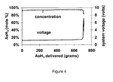
- the mole % of arsine produced by the method of the present invention is at least 90%, more preferably at least 92%, even more preferably at least 94%, and most preferably at least 95%.
- the % purity of the hydride gas generated over the life of the electrochemical cell according to the present invention is at least 99%, more preferably at least 99.9%, and most preferably at least 99.999%.
- the anode 3 consisted of four molybdenum plates (99%) with dimensions 1/8" x 1.5" x 7.5" (3.2mm x 3.8cm x 19cm). They were placed in a vertical-lengthwise, symmetric square-pattern (2" x 2"; 5cm x 5cm) around the central cathode rod and connected via a common electrical conducting stainless steel frame. They had a nominal mass of 1000 grams. The conducting frame was located above the electrolyte solution.
- the cathode 2 consisted of a single arsenic rod, 1.5" (3.8cm) diameter x 6" (15.2cm) height, was mounted vertically and placed in the center of the square pattern formed by the molybdenum plates. A single 1/8" (3.2mm) stainless steel rod was centered within the arsenic rod and extended beyond the top of the arsenic rod to facilitate electrical contact.
- the cathode had a nominal mass of 1000 grams.
- the anodes 3 and cathode 2 were placed in a cylindrical stainless vessel 1 and isolated from the electrically conducting surfaces using polyethylene and Teflon TM liners and spacers.
- the cell was filled with an aqueous solution of potassium hydroxide. The cell was then sealed and electrical contact was made through electrically isolated connections. A single outlet 4 for the gas of the cell was directed to a gas analyzer. A constant current of 2.5 amps was supplied to the electrochemical cell from an external constant current power supply. Gas analysis with a Balzers Pfeiffer QMA-430 Quadrapole Mass Spectrometer confirmed that the principle gases formed in the cell were arsine and hydrogen. The gas formed was also analyzed for composition, using a Lorex Gas Analyzer, Model number PZN-SS-003-4 The mass of arsine produced was confirmed gravimetrically by weighing the electrochemical cell.
- An electrochemical cell was constructed and operated according to the conditions described above. Examples 1 and 2 illustrated in Table 3 were operated with a high concentration of potassium hydroxide (45%). Under these conditions the yield of arsine was 65.7% and 50.0% based on the limiting reagent potassium hydroxide. Inspection of the cell revealed the formation of a large amount of crystals, which substantially filled the space between the anode and cathode.
- Example 1 the purity of the arsenic rod was 99% and the arsine purity was limited to 85% with 15% hydrogen. Increasing the purity of the arsenic to 99.999% increased the gas purity 90% in Example 2.
- Example 1 An electrochemical cell was constructed and operated according to the conditions in Example 1. Examples 3, 4 and 5 were operated at high concentrations of potassium hydroxide (39%) which, based on calculations, were just below the saturation curve. Example 6 was operated at high concentrations of potassium hydroxide (38%) which, based on calculations, was just below the saturation curve. Under these conditions the yield of arsine ranged between 71.4% and 77.8% based on the limiting reagent potassium hydroxide compared to Examples 1 and 2. Inspection of the cell revealed that there were no crystals formed.
- Tables 4 (detailed) and 5 (key results from Table 4) illustrate two important results for a generator which has a limited electrolyte volume of 1 liter.
- the gas quality is improved with lower KOH.
- an optimum in the yield of Arsine occurs at 39% KOH.
- the amount of arsine is limited to the low levels of KOH no matter how efficient the process is.
- the yield in grams is low because the solids formed in the process interfere with the process.
- An undivided temperature controlled electrochemical cell made of Teflon TM will be constructed with an internal volume of 10 cm 3 of liquid.
- a molybdenum anode (99% purity) with a surface area of 2.8 cm 2 will be positioned 3.8 cm from an antimony cathode (>99% purity) with a surface area of 2.8 cm 2 .
- An aqueous electrolyte containing 35% potassium hydroxide will be charged to the cell.
- An electrical potential of 5.0 V will be applied to the cell while the aqueous electrolyte temperature will be maintained at 0°C using an external cooling bath.
- Stibine along with hydrogen will be evolved from the cell.
- a current ranging from 0.6 to 0.8 amps and a stibine production rate of 0.7 mg/min will be obtained.
- An undivided temperature controlled electrochemical cell made of Teflon TM will be constructed with an internal volume of 10 cm 3 of liquid.
- a molybdenum anode (99% purity) with a surface area of 2.8 cm 2 will be positioned 3.8 cm from an antimony cathode (>99% purity) with a surface area of 2.8 cm 2 .
- An aqueous electrolyte containing 35% potassium hydroxide saturated with potassium molybdate, K 2 MoO 4 , and containing free potassium molybdate solids will be charged to the cell.
- An electrical potential of 5.0 V will be applied to the cell while the aqueous electrolyte temperature will be maintained at 0°C using an external cooling bath. Stibine along with hydrogen will be evolved from the cell.
- a current ranging from 0.05 to 0.10 amps and a stibine production rate of 0.08 mg/min will be obtained.
- An undivided temperature controlled electrochemical cell made of Teflon TM will be constructed with an internal volume of 10 cm 3 of liquid.
- a tungsten anode (99% purity) with a surface area of 2.8 cm 2 will be positioned 3.8 cm from an arsenic cathode (>99% purity) with a surface area of 2.8 cm 2 .
- An aqueous electrolyte containing 35% sodium hydroxide will be charged to the cell.
- An electrical potential of 5.0 V will be applied to the cell while the aqueous electrolyte temperature will be maintained at 21 °C using an external cooling bath.
- Arsine along with hydrogen will be evolved from the cell.
- a current ranging from 1.0 to 1.2 amps and an arsine production rate of 16.0 mg/min will be obtained.
- An undivided temperature controlled electrochemical cell made of Teflon TM will be constructed with an internal volume of 10 cm 3 of liquid.
- a tungsten anode (99% purity) with a surface area of 2.8 cm 2 will be positioned 3.8 cm from an arsenic cathode (>99% purity) with a surface area of 2.8 cm 2 .
- An aqueous electrolyte containing 35% sodium hydroxide saturated with potassium tungstate, NaWO 4 , and containing free potassium tungstate solids will be charged to the cell.
- An electrical potential of 5.0 V will be applied to the cell while the aqueous electrolyte temperature will be maintained at 21 °C using an external cooling bath.
- Arsine along with hydrogen will be evolved from the cell.
- a current ranging from 0.15 to 0.2 amps and an arsine production rate of 2.5 mg/min will be obtained.
- An undivided temperature controlled electrochemical cell made of Teflon TM will be constructed with an internal volume of 10 cm 3 of liquid.
- a tungsten anode (99% purity) with a surface area of 2.8 cm 2 will be positioned 3.8 cm from a black phosphorous cathode (>99% purity) with a surface area of 2.8 cm 2 .
- An aqueous electrolyte containing 35% potassium hydroxide will be charged to the cell.
- An electrical potential of 5.0 V will be applied to the cell while the aqueous electrolyte temperature will be maintained at 21 °C using an external cooling bath.
- Phosphine along with hydrogen will be evolved from the cell.
- a current ranging from 1.0 to 1.2 amps and a phosphine production rate of 2.0 mg/min will be obtained.
- An undivided temperature controlled electrochemical cell made of Teflon TM will be constructed with an internal volume of 10 cm 3 of liquid.
- a tungsten anode (99% purity) with a surface area of 2.8 cm 2 will be positioned 3.8 cm from a black phosphorous cathode (>99% purity) with a surface area of 2.8 cm 2 .
- An aqueous electrolyte containing 35% potassium hydroxide saturated with potassium tungstate, K 2 WO 4 , and containing free potassium tungstate solids will be charged to the cell.
- An electrical potential of 5.0 V will be applied to the cell while the aqueous electrolyte temperature will be maintained at 21 °C using an external cooling bath.
- Phosphine along with hydrogen will be evolved from the cell.
- a current ranging from 0.15 to 0.2 amps and a phosphine production rate of 0.3 mg/min will be obtained.
- An undivided temperature controlled electrochemical cell made of Teflon TM will be constructed with an internal volume of 10 cm 3 of liquid.
- a molybdenum anode (99% purity) with a surface area of 2.8 cm 2 will be positioned 3.8 cm from a germanium, Ge, cathode (>99% purity) with a surface area of 2.8 cm 2 .
- An aqueous electrolyte containing 35% potassium hydroxide will be charged to the cell.
- An electrical potential of 5.0 V will be applied to the cell while the aqueous electrolyte temperature will be maintained at 21 °C using an external cooling bath.
- Germane, GeH 4 along with hydrogen will be evolved from the cell.
- a current ranging from 1.0 to 1.2 amps and a germane production rate of 0.5 mg/min will be obtained.
- An undivided temperature controlled electrochemical cell made of Teflon TM will be constructed with an internal volume of 10 cm 3 of liquid.
- a molybdenum anode (99% purity) with a surface area of 2.8 cm 2 will be positioned 3.8 cm from a germanium cathode (>99% purity) with a surface area of 2.8 cm 2 .
- An aqueous electrolyte containing 35% potassium hydroxide saturated with potassium molybdate, K 2 MoO 4 , and containing free potassium molybdate solids will be charged to the cell.
- An electrical potential of 5.0 V will be applied to the cell while the aqueous electrolyte temperature will be maintained at 21 °C using an external cooling bath.
- Germane, GeH 4 along with hydrogen will be evolved from the cell.
- a current ranging from 0.15 to 0.2 amps and a germane production rate of 0.08 mg/min will be obtained.
- Examples 7-14 illustrate that a cell operated with an electrolyte with excess of solids from the anode reaction leads to a lower production rates of the hydride gas compared to operation with an electrolyte which will be not saturated with solids.
Landscapes
- Chemical & Material Sciences (AREA)
- Engineering & Computer Science (AREA)
- Chemical Kinetics & Catalysis (AREA)
- Electrochemistry (AREA)
- Materials Engineering (AREA)
- Metallurgy (AREA)
- Organic Chemistry (AREA)
- General Chemical & Material Sciences (AREA)
- Inorganic Chemistry (AREA)
- Mechanical Engineering (AREA)
- Electrolytic Production Of Non-Metals, Compounds, Apparatuses Therefor (AREA)
- Electrodes For Compound Or Non-Metal Manufacture (AREA)
Applications Claiming Priority (2)
| Application Number | Priority Date | Filing Date | Title |
|---|---|---|---|
| US79184006P | 2006-04-13 | 2006-04-13 | |
| US11/687,947 US8021536B2 (en) | 2006-04-13 | 2007-03-19 | Method and apparatus for achieving maximum yield in the electrolytic preparation of group IV and V hydrides |
Publications (3)
| Publication Number | Publication Date |
|---|---|
| EP1845172A2 true EP1845172A2 (de) | 2007-10-17 |
| EP1845172A3 EP1845172A3 (de) | 2009-04-15 |
| EP1845172B1 EP1845172B1 (de) | 2010-07-14 |
Family
ID=38330803
Family Applications (1)
| Application Number | Title | Priority Date | Filing Date |
|---|---|---|---|
| EP07251583A Not-in-force EP1845172B1 (de) | 2006-04-13 | 2007-04-13 | Verfahren und Vorrichtung zum Erzielen der maximalen Menge bei der elektrolytischen Herstellung von Hydriden der Gruppen IV und V |
Country Status (8)
| Country | Link |
|---|---|
| US (2) | US8021536B2 (de) |
| EP (1) | EP1845172B1 (de) |
| JP (2) | JP4842878B2 (de) |
| KR (1) | KR100870161B1 (de) |
| CN (1) | CN101104938B (de) |
| AT (1) | ATE474075T1 (de) |
| DE (1) | DE602007007684D1 (de) |
| TW (1) | TWI363106B (de) |
Families Citing this family (11)
| Publication number | Priority date | Publication date | Assignee | Title |
|---|---|---|---|---|
| US20090159454A1 (en) * | 2007-12-20 | 2009-06-25 | Air Products And Chemicals, Inc. | Divided electrochemical cell and low cost high purity hydride gas production process |
| CN106207203B (zh) * | 2016-07-28 | 2018-09-14 | 华南理工大学 | 一种纳米片状Ni(OH)2催化剂及其制备方法和应用 |
| JP7030115B2 (ja) * | 2017-05-19 | 2022-03-04 | 昭和電工株式会社 | 電気化学的にゲルマンを製造する方法 |
| JP7030114B2 (ja) * | 2017-05-19 | 2022-03-04 | 昭和電工株式会社 | 電気化学的にゲルマンを製造する方法 |
| WO2018212007A1 (ja) * | 2017-05-19 | 2018-11-22 | 昭和電工株式会社 | 電気化学的にゲルマンを製造する方法 |
| CN108760435A (zh) * | 2018-07-18 | 2018-11-06 | 天津师范大学 | 一种用来制备元素氢化物的电化学装置及用途 |
| WO2020113089A1 (en) * | 2018-11-28 | 2020-06-04 | Ayers Group, LLC | Method and apparatus for energy efficient electrochemical production of hydride gases |
| CN111378979B (zh) * | 2018-12-29 | 2022-03-15 | 紫石能源有限公司 | 砷纳米颗粒及其制备方法、电解制砷烷的系统和方法 |
| CN111979558B (zh) * | 2019-05-21 | 2023-08-01 | 紫石能源有限公司 | 电解法制备硒化氢的方法和设备 |
| WO2022118934A1 (ja) * | 2020-12-04 | 2022-06-09 | Eneos株式会社 | 有機ハイドライド製造システム、有機ハイドライド製造システムの制御装置および有機ハイドライド製造システムの制御方法 |
| WO2022189676A1 (en) * | 2021-03-12 | 2022-09-15 | Friedrich-Schiller-Universität Jena | In-situ electrochemical cell with simultaneous thermal analysis |
Family Cites Families (13)
| Publication number | Priority date | Publication date | Assignee | Title |
|---|---|---|---|---|
| US4178224A (en) | 1978-01-19 | 1979-12-11 | Texas Instruments Incorporated | Apparatus for generation and control of dopant and reactive gases |
| JPH01139781A (ja) | 1987-11-26 | 1989-06-01 | Seitetsu Kagaku Co Ltd | ホスフィンの製造方法 |
| US5474659A (en) | 1989-04-18 | 1995-12-12 | At&T Corp. | Process and apparatus for generating precursor gases used in the manufacture of semiconductor devices |
| CA2010482C (en) | 1989-04-18 | 1998-08-25 | Gardy Cadet | Process for the fabrication of devices; utilizing electrochemically generated gases |
| US5158656A (en) | 1991-03-22 | 1992-10-27 | Electron Transfer Technologies, Inc. | Method and apparatus for the electrolytic preparation of group IV and V hydrides |
| FR2710043B1 (fr) | 1993-09-17 | 1995-10-13 | Air Liquide | Procédé et dispositif de génération d'arsine par voie électrolytique. |
| US5630933A (en) | 1995-07-14 | 1997-05-20 | Lucent Technologies Inc. | Processes involving metal hydrides |
| US5925232A (en) | 1995-12-06 | 1999-07-20 | Electron Tranfer Technologies | Method and apparatus for constant composition delivery of hydride gases for semiconductor processing |
| JPH108280A (ja) | 1996-06-21 | 1998-01-13 | Furukawa Battery Co Ltd:The | 化合物の製造方法 |
| US6080297A (en) | 1996-12-06 | 2000-06-27 | Electron Transfer Technologies, Inc. | Method and apparatus for constant composition delivery of hydride gases for semiconductor processing |
| CN1239748C (zh) * | 2002-08-10 | 2006-02-01 | 太原理工大学 | 电解法制备硼氢化物的工艺 |
| RU2230830C1 (ru) | 2003-07-08 | 2004-06-20 | Общество с ограниченной ответственностью "Фирма "ХОРСТ" | Способ получения высокочистого гидрида германия (варианты) |
| CA2503297C (en) * | 2004-04-13 | 2009-10-20 | Rohm And Haas Company | Electrolytic method for producing borohydride |
-
2007
- 2007-03-19 US US11/687,947 patent/US8021536B2/en active Active
- 2007-04-10 TW TW096112613A patent/TWI363106B/zh not_active IP Right Cessation
- 2007-04-12 JP JP2007105115A patent/JP4842878B2/ja not_active Expired - Fee Related
- 2007-04-13 DE DE602007007684T patent/DE602007007684D1/de active Active
- 2007-04-13 AT AT07251583T patent/ATE474075T1/de not_active IP Right Cessation
- 2007-04-13 CN CN2007101053487A patent/CN101104938B/zh not_active Expired - Fee Related
- 2007-04-13 EP EP07251583A patent/EP1845172B1/de not_active Not-in-force
- 2007-04-13 KR KR1020070036471A patent/KR100870161B1/ko not_active Expired - Fee Related
-
2011
- 2011-03-15 JP JP2011056443A patent/JP2011137241A/ja active Pending
- 2011-08-12 US US13/208,418 patent/US8591720B2/en not_active Expired - Fee Related
Also Published As
| Publication number | Publication date |
|---|---|
| EP1845172B1 (de) | 2010-07-14 |
| US20120205252A1 (en) | 2012-08-16 |
| KR20070101815A (ko) | 2007-10-17 |
| US8021536B2 (en) | 2011-09-20 |
| JP2007284790A (ja) | 2007-11-01 |
| ATE474075T1 (de) | 2010-07-15 |
| TWI363106B (en) | 2012-05-01 |
| US8591720B2 (en) | 2013-11-26 |
| JP2011137241A (ja) | 2011-07-14 |
| CN101104938A (zh) | 2008-01-16 |
| US20070240997A1 (en) | 2007-10-18 |
| CN101104938B (zh) | 2011-08-03 |
| DE602007007684D1 (de) | 2010-08-26 |
| TW200738910A (en) | 2007-10-16 |
| JP4842878B2 (ja) | 2011-12-21 |
| KR100870161B1 (ko) | 2008-11-24 |
| EP1845172A3 (de) | 2009-04-15 |
Similar Documents
| Publication | Publication Date | Title |
|---|---|---|
| EP1845172B1 (de) | Verfahren und Vorrichtung zum Erzielen der maximalen Menge bei der elektrolytischen Herstellung von Hydriden der Gruppen IV und V | |
| US6080297A (en) | Method and apparatus for constant composition delivery of hydride gases for semiconductor processing | |
| EP2072640B1 (de) | Geteilte elektrochemische Zelle und Herstellungsverfahren von hochreinem Metallhydridgas | |
| Jeong et al. | Electrolytic production of metallic uranium from U3O8 in a 20-kg batch scale reactor | |
| Ling et al. | Strain induced rich planar defects in heterogeneous WS 2/WO 2 enable efficient nitrogen fixation at low overpotential | |
| US10988847B2 (en) | Apparatus and method of preparing carbonate and/or formate from carbon dioxide | |
| US20200115806A1 (en) | Hydrogen generator | |
| JP2009149987A5 (de) | ||
| JP3889813B2 (ja) | 半導体加工用の水素化物ガスを一定組成で供給するための方法と装置 | |
| US5158656A (en) | Method and apparatus for the electrolytic preparation of group IV and V hydrides | |
| Wang et al. | A Self‐Recycling Ruthenium Incorporated CuFe2O4 Electrocatalyst for Efficient Neutral Ammonia Electrosynthesis | |
| Sulaiman et al. | Phase transition and electrocatalytic properties of a 1-dimensional NiMo amorphous-crystalline alloy for the alkaline hydrogen evolution reaction | |
| EP4136277B1 (de) | Material auf kupfer- und antimonbasis und elektrode zur selektiven umwandlung von kohlendioxid in kohlenmonoxid | |
| US12540410B2 (en) | Method and apparatus for energy efficient electrochemical production of hydride gases | |
| Jiang | Theory-guided design of nanoporous CuMn alloy for efficient electrocatalytic nitrogen reduction to ammonia | |
| EP4700864A1 (de) | Lithiummetallverbundoxidpulver, positivelektrodenaktivmaterial für eine feststoffsekundärbatterie, positivelektrode für eine feststoffsekundärbatterie und feststoffsekundärbatterie |
Legal Events
| Date | Code | Title | Description |
|---|---|---|---|
| PUAI | Public reference made under article 153(3) epc to a published international application that has entered the european phase |
Free format text: ORIGINAL CODE: 0009012 |
|
| AK | Designated contracting states |
Kind code of ref document: A2 Designated state(s): AT BE BG CH CY CZ DE DK EE ES FI FR GB GR HU IE IS IT LI LT LU LV MC MT NL PL PT RO SE SI SK TR |
|
| AX | Request for extension of the european patent |
Extension state: AL BA HR MK YU |
|
| PUAL | Search report despatched |
Free format text: ORIGINAL CODE: 0009013 |
|
| AK | Designated contracting states |
Kind code of ref document: A3 Designated state(s): AT BE BG CH CY CZ DE DK EE ES FI FR GB GR HU IE IS IT LI LT LU LV MC MT NL PL PT RO SE SI SK TR |
|
| AX | Request for extension of the european patent |
Extension state: AL BA HR MK RS |
|
| 17P | Request for examination filed |
Effective date: 20090911 |
|
| AKX | Designation fees paid |
Designated state(s): AT BE BG CH CY CZ DE DK EE ES FI FR GB GR HU IE IS IT LI LT LU LV MC MT NL PL PT RO SE SI SK TR |
|
| GRAP | Despatch of communication of intention to grant a patent |
Free format text: ORIGINAL CODE: EPIDOSNIGR1 |
|
| GRAS | Grant fee paid |
Free format text: ORIGINAL CODE: EPIDOSNIGR3 |
|
| GRAA | (expected) grant |
Free format text: ORIGINAL CODE: 0009210 |
|
| AK | Designated contracting states |
Kind code of ref document: B1 Designated state(s): AT BE BG CH CY CZ DE DK EE ES FI FR GB GR HU IE IS IT LI LT LU LV MC MT NL PL PT RO SE SI SK TR |
|
| REG | Reference to a national code |
Ref country code: GB Ref legal event code: FG4D |
|
| REG | Reference to a national code |
Ref country code: CH Ref legal event code: EP |
|
| REG | Reference to a national code |
Ref country code: IE Ref legal event code: FG4D |
|
| REF | Corresponds to: |
Ref document number: 602007007684 Country of ref document: DE Date of ref document: 20100826 Kind code of ref document: P |
|
| REG | Reference to a national code |
Ref country code: NL Ref legal event code: VDEP Effective date: 20100714 |
|
| LTIE | Lt: invalidation of european patent or patent extension |
Effective date: 20100714 |
|
| PG25 | Lapsed in a contracting state [announced via postgrant information from national office to epo] |
Ref country code: NL Free format text: LAPSE BECAUSE OF FAILURE TO SUBMIT A TRANSLATION OF THE DESCRIPTION OR TO PAY THE FEE WITHIN THE PRESCRIBED TIME-LIMIT Effective date: 20100714 Ref country code: AT Free format text: LAPSE BECAUSE OF FAILURE TO SUBMIT A TRANSLATION OF THE DESCRIPTION OR TO PAY THE FEE WITHIN THE PRESCRIBED TIME-LIMIT Effective date: 20100714 Ref country code: FI Free format text: LAPSE BECAUSE OF FAILURE TO SUBMIT A TRANSLATION OF THE DESCRIPTION OR TO PAY THE FEE WITHIN THE PRESCRIBED TIME-LIMIT Effective date: 20100714 Ref country code: LT Free format text: LAPSE BECAUSE OF FAILURE TO SUBMIT A TRANSLATION OF THE DESCRIPTION OR TO PAY THE FEE WITHIN THE PRESCRIBED TIME-LIMIT Effective date: 20100714 |
|
| PG25 | Lapsed in a contracting state [announced via postgrant information from national office to epo] |
Ref country code: SI Free format text: LAPSE BECAUSE OF FAILURE TO SUBMIT A TRANSLATION OF THE DESCRIPTION OR TO PAY THE FEE WITHIN THE PRESCRIBED TIME-LIMIT Effective date: 20100714 Ref country code: BG Free format text: LAPSE BECAUSE OF FAILURE TO SUBMIT A TRANSLATION OF THE DESCRIPTION OR TO PAY THE FEE WITHIN THE PRESCRIBED TIME-LIMIT Effective date: 20101014 Ref country code: CY Free format text: LAPSE BECAUSE OF FAILURE TO SUBMIT A TRANSLATION OF THE DESCRIPTION OR TO PAY THE FEE WITHIN THE PRESCRIBED TIME-LIMIT Effective date: 20100714 Ref country code: IS Free format text: LAPSE BECAUSE OF FAILURE TO SUBMIT A TRANSLATION OF THE DESCRIPTION OR TO PAY THE FEE WITHIN THE PRESCRIBED TIME-LIMIT Effective date: 20101114 Ref country code: PL Free format text: LAPSE BECAUSE OF FAILURE TO SUBMIT A TRANSLATION OF THE DESCRIPTION OR TO PAY THE FEE WITHIN THE PRESCRIBED TIME-LIMIT Effective date: 20100714 Ref country code: PT Free format text: LAPSE BECAUSE OF FAILURE TO SUBMIT A TRANSLATION OF THE DESCRIPTION OR TO PAY THE FEE WITHIN THE PRESCRIBED TIME-LIMIT Effective date: 20101115 |
|
| PG25 | Lapsed in a contracting state [announced via postgrant information from national office to epo] |
Ref country code: GR Free format text: LAPSE BECAUSE OF FAILURE TO SUBMIT A TRANSLATION OF THE DESCRIPTION OR TO PAY THE FEE WITHIN THE PRESCRIBED TIME-LIMIT Effective date: 20101015 Ref country code: LV Free format text: LAPSE BECAUSE OF FAILURE TO SUBMIT A TRANSLATION OF THE DESCRIPTION OR TO PAY THE FEE WITHIN THE PRESCRIBED TIME-LIMIT Effective date: 20100714 Ref country code: SE Free format text: LAPSE BECAUSE OF FAILURE TO SUBMIT A TRANSLATION OF THE DESCRIPTION OR TO PAY THE FEE WITHIN THE PRESCRIBED TIME-LIMIT Effective date: 20100714 Ref country code: BE Free format text: LAPSE BECAUSE OF FAILURE TO SUBMIT A TRANSLATION OF THE DESCRIPTION OR TO PAY THE FEE WITHIN THE PRESCRIBED TIME-LIMIT Effective date: 20100714 |
|
| PG25 | Lapsed in a contracting state [announced via postgrant information from national office to epo] |
Ref country code: DK Free format text: LAPSE BECAUSE OF FAILURE TO SUBMIT A TRANSLATION OF THE DESCRIPTION OR TO PAY THE FEE WITHIN THE PRESCRIBED TIME-LIMIT Effective date: 20100714 |
|
| PLBE | No opposition filed within time limit |
Free format text: ORIGINAL CODE: 0009261 |
|
| STAA | Information on the status of an ep patent application or granted ep patent |
Free format text: STATUS: NO OPPOSITION FILED WITHIN TIME LIMIT |
|
| PG25 | Lapsed in a contracting state [announced via postgrant information from national office to epo] |
Ref country code: RO Free format text: LAPSE BECAUSE OF FAILURE TO SUBMIT A TRANSLATION OF THE DESCRIPTION OR TO PAY THE FEE WITHIN THE PRESCRIBED TIME-LIMIT Effective date: 20100714 Ref country code: EE Free format text: LAPSE BECAUSE OF FAILURE TO SUBMIT A TRANSLATION OF THE DESCRIPTION OR TO PAY THE FEE WITHIN THE PRESCRIBED TIME-LIMIT Effective date: 20100714 Ref country code: CZ Free format text: LAPSE BECAUSE OF FAILURE TO SUBMIT A TRANSLATION OF THE DESCRIPTION OR TO PAY THE FEE WITHIN THE PRESCRIBED TIME-LIMIT Effective date: 20100714 Ref country code: SK Free format text: LAPSE BECAUSE OF FAILURE TO SUBMIT A TRANSLATION OF THE DESCRIPTION OR TO PAY THE FEE WITHIN THE PRESCRIBED TIME-LIMIT Effective date: 20100714 |
|
| 26N | No opposition filed |
Effective date: 20110415 |
|
| PG25 | Lapsed in a contracting state [announced via postgrant information from national office to epo] |
Ref country code: ES Free format text: LAPSE BECAUSE OF FAILURE TO SUBMIT A TRANSLATION OF THE DESCRIPTION OR TO PAY THE FEE WITHIN THE PRESCRIBED TIME-LIMIT Effective date: 20101025 |
|
| REG | Reference to a national code |
Ref country code: DE Ref legal event code: R097 Ref document number: 602007007684 Country of ref document: DE Effective date: 20110415 |
|
| PG25 | Lapsed in a contracting state [announced via postgrant information from national office to epo] |
Ref country code: MC Free format text: LAPSE BECAUSE OF NON-PAYMENT OF DUE FEES Effective date: 20110430 |
|
| REG | Reference to a national code |
Ref country code: CH Ref legal event code: PL |
|
| PG25 | Lapsed in a contracting state [announced via postgrant information from national office to epo] |
Ref country code: MT Free format text: LAPSE BECAUSE OF FAILURE TO SUBMIT A TRANSLATION OF THE DESCRIPTION OR TO PAY THE FEE WITHIN THE PRESCRIBED TIME-LIMIT Effective date: 20100714 |
|
| PG25 | Lapsed in a contracting state [announced via postgrant information from national office to epo] |
Ref country code: LI Free format text: LAPSE BECAUSE OF NON-PAYMENT OF DUE FEES Effective date: 20110430 Ref country code: CH Free format text: LAPSE BECAUSE OF NON-PAYMENT OF DUE FEES Effective date: 20110430 |
|
| REG | Reference to a national code |
Ref country code: IE Ref legal event code: MM4A |
|
| PG25 | Lapsed in a contracting state [announced via postgrant information from national office to epo] |
Ref country code: IE Free format text: LAPSE BECAUSE OF NON-PAYMENT OF DUE FEES Effective date: 20110413 |
|
| PG25 | Lapsed in a contracting state [announced via postgrant information from national office to epo] |
Ref country code: LU Free format text: LAPSE BECAUSE OF NON-PAYMENT OF DUE FEES Effective date: 20110413 |
|
| PG25 | Lapsed in a contracting state [announced via postgrant information from national office to epo] |
Ref country code: TR Free format text: LAPSE BECAUSE OF FAILURE TO SUBMIT A TRANSLATION OF THE DESCRIPTION OR TO PAY THE FEE WITHIN THE PRESCRIBED TIME-LIMIT Effective date: 20100714 |
|
| PG25 | Lapsed in a contracting state [announced via postgrant information from national office to epo] |
Ref country code: HU Free format text: LAPSE BECAUSE OF FAILURE TO SUBMIT A TRANSLATION OF THE DESCRIPTION OR TO PAY THE FEE WITHIN THE PRESCRIBED TIME-LIMIT Effective date: 20100714 |
|
| REG | Reference to a national code |
Ref country code: FR Ref legal event code: PLFP Year of fee payment: 9 |
|
| REG | Reference to a national code |
Ref country code: FR Ref legal event code: PLFP Year of fee payment: 10 |
|
| REG | Reference to a national code |
Ref country code: FR Ref legal event code: PLFP Year of fee payment: 11 |
|
| REG | Reference to a national code |
Ref country code: GB Ref legal event code: 732E Free format text: REGISTERED BETWEEN 20171123 AND 20171129 |
|
| REG | Reference to a national code |
Ref country code: FR Ref legal event code: PLFP Year of fee payment: 12 |
|
| P01 | Opt-out of the competence of the unified patent court (upc) registered |
Effective date: 20230602 |
|
| PGFP | Annual fee paid to national office [announced via postgrant information from national office to epo] |
Ref country code: GB Payment date: 20240307 Year of fee payment: 18 |
|
| PGFP | Annual fee paid to national office [announced via postgrant information from national office to epo] |
Ref country code: IT Payment date: 20240313 Year of fee payment: 18 Ref country code: FR Payment date: 20240308 Year of fee payment: 18 |
|
| PGFP | Annual fee paid to national office [announced via postgrant information from national office to epo] |
Ref country code: DE Payment date: 20240306 Year of fee payment: 18 |
|
| REG | Reference to a national code |
Ref country code: DE Ref legal event code: R119 Ref document number: 602007007684 Country of ref document: DE |
|
| GBPC | Gb: european patent ceased through non-payment of renewal fee |
Effective date: 20250413 |
|
| PG25 | Lapsed in a contracting state [announced via postgrant information from national office to epo] |
Ref country code: DE Free format text: LAPSE BECAUSE OF NON-PAYMENT OF DUE FEES Effective date: 20251104 |
|
| PG25 | Lapsed in a contracting state [announced via postgrant information from national office to epo] |
Ref country code: GB Free format text: LAPSE BECAUSE OF NON-PAYMENT OF DUE FEES Effective date: 20250413 |
|
| PG25 | Lapsed in a contracting state [announced via postgrant information from national office to epo] |
Ref country code: FR Free format text: LAPSE BECAUSE OF NON-PAYMENT OF DUE FEES Effective date: 20250430 |
|
| PG25 | Lapsed in a contracting state [announced via postgrant information from national office to epo] |
Ref country code: IT Free format text: LAPSE BECAUSE OF NON-PAYMENT OF DUE FEES Effective date: 20250413 |