EP1843195A2 - Display apparatus - Google Patents
Display apparatus Download PDFInfo
- Publication number
- EP1843195A2 EP1843195A2 EP07006154A EP07006154A EP1843195A2 EP 1843195 A2 EP1843195 A2 EP 1843195A2 EP 07006154 A EP07006154 A EP 07006154A EP 07006154 A EP07006154 A EP 07006154A EP 1843195 A2 EP1843195 A2 EP 1843195A2
- Authority
- EP
- European Patent Office
- Prior art keywords
- pixel
- sub
- electrode
- main
- pixel electrode
- Prior art date
- Legal status (The legal status is an assumption and is not a legal conclusion. Google has not performed a legal analysis and makes no representation as to the accuracy of the status listed.)
- Granted
Links
- 239000000758 substrate Substances 0.000 claims abstract description 44
- 239000010409 thin film Substances 0.000 claims description 35
- 239000012044 organic layer Substances 0.000 claims description 12
- 239000004973 liquid crystal related substance Substances 0.000 description 63
- 239000010410 layer Substances 0.000 description 24
- 230000005684 electric field Effects 0.000 description 18
- 239000000463 material Substances 0.000 description 9
- 239000011241 protective layer Substances 0.000 description 8
- 230000003287 optical effect Effects 0.000 description 7
- 230000000903 blocking effect Effects 0.000 description 6
- 229910052751 metal Inorganic materials 0.000 description 6
- 239000002184 metal Substances 0.000 description 6
- 239000003990 capacitor Substances 0.000 description 5
- 239000004065 semiconductor Substances 0.000 description 5
- 238000002834 transmittance Methods 0.000 description 4
- 229910021417 amorphous silicon Inorganic materials 0.000 description 3
- RYGMFSIKBFXOCR-UHFFFAOYSA-N Copper Chemical compound [Cu] RYGMFSIKBFXOCR-UHFFFAOYSA-N 0.000 description 2
- 229910052581 Si3N4 Inorganic materials 0.000 description 2
- 229910052782 aluminium Inorganic materials 0.000 description 2
- XAGFODPZIPBFFR-UHFFFAOYSA-N aluminium Chemical compound [Al] XAGFODPZIPBFFR-UHFFFAOYSA-N 0.000 description 2
- 229910052802 copper Inorganic materials 0.000 description 2
- 239000010949 copper Substances 0.000 description 2
- 230000008878 coupling Effects 0.000 description 2
- 238000010168 coupling process Methods 0.000 description 2
- 238000005859 coupling reaction Methods 0.000 description 2
- 150000002739 metals Chemical class 0.000 description 2
- 238000000059 patterning Methods 0.000 description 2
- 230000000704 physical effect Effects 0.000 description 2
- HQVNEWCFYHHQES-UHFFFAOYSA-N silicon nitride Chemical compound N12[Si]34N5[Si]62N3[Si]51N64 HQVNEWCFYHHQES-UHFFFAOYSA-N 0.000 description 2
- 239000002356 single layer Substances 0.000 description 2
- VYZAMTAEIAYCRO-UHFFFAOYSA-N Chromium Chemical compound [Cr] VYZAMTAEIAYCRO-UHFFFAOYSA-N 0.000 description 1
- ZOKXTWBITQBERF-UHFFFAOYSA-N Molybdenum Chemical compound [Mo] ZOKXTWBITQBERF-UHFFFAOYSA-N 0.000 description 1
- BQCADISMDOOEFD-UHFFFAOYSA-N Silver Chemical compound [Ag] BQCADISMDOOEFD-UHFFFAOYSA-N 0.000 description 1
- RTAQQCXQSZGOHL-UHFFFAOYSA-N Titanium Chemical compound [Ti] RTAQQCXQSZGOHL-UHFFFAOYSA-N 0.000 description 1
- 230000015556 catabolic process Effects 0.000 description 1
- 230000008859 change Effects 0.000 description 1
- 239000003086 colorant Substances 0.000 description 1
- 239000013078 crystal Substances 0.000 description 1
- 238000006731 degradation reaction Methods 0.000 description 1
- 238000000151 deposition Methods 0.000 description 1
- 239000002355 dual-layer Substances 0.000 description 1
- 230000000694 effects Effects 0.000 description 1
- 239000012535 impurity Substances 0.000 description 1
- AMGQUBHHOARCQH-UHFFFAOYSA-N indium;oxotin Chemical compound [In].[Sn]=O AMGQUBHHOARCQH-UHFFFAOYSA-N 0.000 description 1
- 150000002500 ions Chemical class 0.000 description 1
- 230000004048 modification Effects 0.000 description 1
- 238000012986 modification Methods 0.000 description 1
- 229910052750 molybdenum Inorganic materials 0.000 description 1
- 239000011733 molybdenum Substances 0.000 description 1
- 230000004044 response Effects 0.000 description 1
- 229910052709 silver Inorganic materials 0.000 description 1
- 239000004332 silver Substances 0.000 description 1
- 229910052715 tantalum Inorganic materials 0.000 description 1
- GUVRBAGPIYLISA-UHFFFAOYSA-N tantalum atom Chemical compound [Ta] GUVRBAGPIYLISA-UHFFFAOYSA-N 0.000 description 1
- 229910052719 titanium Inorganic materials 0.000 description 1
- 239000010936 titanium Substances 0.000 description 1
- 239000012780 transparent material Substances 0.000 description 1
- YVTHLONGBIQYBO-UHFFFAOYSA-N zinc indium(3+) oxygen(2-) Chemical compound [O--].[Zn++].[In+3] YVTHLONGBIQYBO-UHFFFAOYSA-N 0.000 description 1
Images


Classifications
-
- G—PHYSICS
- G02—OPTICS
- G02F—OPTICAL DEVICES OR ARRANGEMENTS FOR THE CONTROL OF LIGHT BY MODIFICATION OF THE OPTICAL PROPERTIES OF THE MEDIA OF THE ELEMENTS INVOLVED THEREIN; NON-LINEAR OPTICS; FREQUENCY-CHANGING OF LIGHT; OPTICAL LOGIC ELEMENTS; OPTICAL ANALOGUE/DIGITAL CONVERTERS
- G02F1/00—Devices or arrangements for the control of the intensity, colour, phase, polarisation or direction of light arriving from an independent light source, e.g. switching, gating or modulating; Non-linear optics
- G02F1/01—Devices or arrangements for the control of the intensity, colour, phase, polarisation or direction of light arriving from an independent light source, e.g. switching, gating or modulating; Non-linear optics for the control of the intensity, phase, polarisation or colour
- G02F1/13—Devices or arrangements for the control of the intensity, colour, phase, polarisation or direction of light arriving from an independent light source, e.g. switching, gating or modulating; Non-linear optics for the control of the intensity, phase, polarisation or colour based on liquid crystals, e.g. single liquid crystal display cells
- G02F1/133—Constructional arrangements; Operation of liquid crystal cells; Circuit arrangements
- G02F1/1333—Constructional arrangements; Manufacturing methods
- G02F1/1343—Electrodes
- G02F1/134309—Electrodes characterised by their geometrical arrangement
-
- G—PHYSICS
- G02—OPTICS
- G02F—OPTICAL DEVICES OR ARRANGEMENTS FOR THE CONTROL OF LIGHT BY MODIFICATION OF THE OPTICAL PROPERTIES OF THE MEDIA OF THE ELEMENTS INVOLVED THEREIN; NON-LINEAR OPTICS; FREQUENCY-CHANGING OF LIGHT; OPTICAL LOGIC ELEMENTS; OPTICAL ANALOGUE/DIGITAL CONVERTERS
- G02F1/00—Devices or arrangements for the control of the intensity, colour, phase, polarisation or direction of light arriving from an independent light source, e.g. switching, gating or modulating; Non-linear optics
- G02F1/01—Devices or arrangements for the control of the intensity, colour, phase, polarisation or direction of light arriving from an independent light source, e.g. switching, gating or modulating; Non-linear optics for the control of the intensity, phase, polarisation or colour
- G02F1/13—Devices or arrangements for the control of the intensity, colour, phase, polarisation or direction of light arriving from an independent light source, e.g. switching, gating or modulating; Non-linear optics for the control of the intensity, phase, polarisation or colour based on liquid crystals, e.g. single liquid crystal display cells
- G02F1/133—Constructional arrangements; Operation of liquid crystal cells; Circuit arrangements
- G02F1/1333—Constructional arrangements; Manufacturing methods
- G02F1/1343—Electrodes
-
- G—PHYSICS
- G02—OPTICS
- G02F—OPTICAL DEVICES OR ARRANGEMENTS FOR THE CONTROL OF LIGHT BY MODIFICATION OF THE OPTICAL PROPERTIES OF THE MEDIA OF THE ELEMENTS INVOLVED THEREIN; NON-LINEAR OPTICS; FREQUENCY-CHANGING OF LIGHT; OPTICAL LOGIC ELEMENTS; OPTICAL ANALOGUE/DIGITAL CONVERTERS
- G02F1/00—Devices or arrangements for the control of the intensity, colour, phase, polarisation or direction of light arriving from an independent light source, e.g. switching, gating or modulating; Non-linear optics
- G02F1/01—Devices or arrangements for the control of the intensity, colour, phase, polarisation or direction of light arriving from an independent light source, e.g. switching, gating or modulating; Non-linear optics for the control of the intensity, phase, polarisation or colour
- G02F1/13—Devices or arrangements for the control of the intensity, colour, phase, polarisation or direction of light arriving from an independent light source, e.g. switching, gating or modulating; Non-linear optics for the control of the intensity, phase, polarisation or colour based on liquid crystals, e.g. single liquid crystal display cells
- G02F1/133—Constructional arrangements; Operation of liquid crystal cells; Circuit arrangements
- G02F1/1333—Constructional arrangements; Manufacturing methods
- G02F1/1337—Surface-induced orientation of the liquid crystal molecules, e.g. by alignment layers
- G02F1/133707—Structures for producing distorted electric fields, e.g. bumps, protrusions, recesses, slits in pixel electrodes
-
- G—PHYSICS
- G09—EDUCATION; CRYPTOGRAPHY; DISPLAY; ADVERTISING; SEALS
- G09G—ARRANGEMENTS OR CIRCUITS FOR CONTROL OF INDICATING DEVICES USING STATIC MEANS TO PRESENT VARIABLE INFORMATION
- G09G3/00—Control arrangements or circuits, of interest only in connection with visual indicators other than cathode-ray tubes
- G09G3/20—Control arrangements or circuits, of interest only in connection with visual indicators other than cathode-ray tubes for presentation of an assembly of a number of characters, e.g. a page, by composing the assembly by combination of individual elements arranged in a matrix no fixed position being assigned to or needed to be assigned to the individual characters or partial characters
- G09G3/34—Control arrangements or circuits, of interest only in connection with visual indicators other than cathode-ray tubes for presentation of an assembly of a number of characters, e.g. a page, by composing the assembly by combination of individual elements arranged in a matrix no fixed position being assigned to or needed to be assigned to the individual characters or partial characters by control of light from an independent source
- G09G3/36—Control arrangements or circuits, of interest only in connection with visual indicators other than cathode-ray tubes for presentation of an assembly of a number of characters, e.g. a page, by composing the assembly by combination of individual elements arranged in a matrix no fixed position being assigned to or needed to be assigned to the individual characters or partial characters by control of light from an independent source using liquid crystals
- G09G3/3611—Control of matrices with row and column drivers
- G09G3/3648—Control of matrices with row and column drivers using an active matrix
-
- G—PHYSICS
- G02—OPTICS
- G02F—OPTICAL DEVICES OR ARRANGEMENTS FOR THE CONTROL OF LIGHT BY MODIFICATION OF THE OPTICAL PROPERTIES OF THE MEDIA OF THE ELEMENTS INVOLVED THEREIN; NON-LINEAR OPTICS; FREQUENCY-CHANGING OF LIGHT; OPTICAL LOGIC ELEMENTS; OPTICAL ANALOGUE/DIGITAL CONVERTERS
- G02F1/00—Devices or arrangements for the control of the intensity, colour, phase, polarisation or direction of light arriving from an independent light source, e.g. switching, gating or modulating; Non-linear optics
- G02F1/01—Devices or arrangements for the control of the intensity, colour, phase, polarisation or direction of light arriving from an independent light source, e.g. switching, gating or modulating; Non-linear optics for the control of the intensity, phase, polarisation or colour
- G02F1/13—Devices or arrangements for the control of the intensity, colour, phase, polarisation or direction of light arriving from an independent light source, e.g. switching, gating or modulating; Non-linear optics for the control of the intensity, phase, polarisation or colour based on liquid crystals, e.g. single liquid crystal display cells
- G02F1/133—Constructional arrangements; Operation of liquid crystal cells; Circuit arrangements
- G02F1/1333—Constructional arrangements; Manufacturing methods
- G02F1/1343—Electrodes
- G02F1/134309—Electrodes characterised by their geometrical arrangement
- G02F1/134345—Subdivided pixels, e.g. for grey scale or redundancy
-
- G—PHYSICS
- G02—OPTICS
- G02F—OPTICAL DEVICES OR ARRANGEMENTS FOR THE CONTROL OF LIGHT BY MODIFICATION OF THE OPTICAL PROPERTIES OF THE MEDIA OF THE ELEMENTS INVOLVED THEREIN; NON-LINEAR OPTICS; FREQUENCY-CHANGING OF LIGHT; OPTICAL LOGIC ELEMENTS; OPTICAL ANALOGUE/DIGITAL CONVERTERS
- G02F1/00—Devices or arrangements for the control of the intensity, colour, phase, polarisation or direction of light arriving from an independent light source, e.g. switching, gating or modulating; Non-linear optics
- G02F1/01—Devices or arrangements for the control of the intensity, colour, phase, polarisation or direction of light arriving from an independent light source, e.g. switching, gating or modulating; Non-linear optics for the control of the intensity, phase, polarisation or colour
- G02F1/13—Devices or arrangements for the control of the intensity, colour, phase, polarisation or direction of light arriving from an independent light source, e.g. switching, gating or modulating; Non-linear optics for the control of the intensity, phase, polarisation or colour based on liquid crystals, e.g. single liquid crystal display cells
- G02F1/133—Constructional arrangements; Operation of liquid crystal cells; Circuit arrangements
- G02F1/1333—Constructional arrangements; Manufacturing methods
- G02F1/1343—Electrodes
- G02F1/134309—Electrodes characterised by their geometrical arrangement
- G02F1/134381—Hybrid switching mode, i.e. for applying an electric field with components parallel and orthogonal to the substrates
-
- G—PHYSICS
- G09—EDUCATION; CRYPTOGRAPHY; DISPLAY; ADVERTISING; SEALS
- G09G—ARRANGEMENTS OR CIRCUITS FOR CONTROL OF INDICATING DEVICES USING STATIC MEANS TO PRESENT VARIABLE INFORMATION
- G09G2300/00—Aspects of the constitution of display devices
- G09G2300/04—Structural and physical details of display devices
- G09G2300/0439—Pixel structures
- G09G2300/0443—Pixel structures with several sub-pixels for the same colour in a pixel, not specifically used to display gradations
- G09G2300/0447—Pixel structures with several sub-pixels for the same colour in a pixel, not specifically used to display gradations for multi-domain technique to improve the viewing angle in a liquid crystal display, such as multi-vertical alignment [MVA]
-
- G—PHYSICS
- G09—EDUCATION; CRYPTOGRAPHY; DISPLAY; ADVERTISING; SEALS
- G09G—ARRANGEMENTS OR CIRCUITS FOR CONTROL OF INDICATING DEVICES USING STATIC MEANS TO PRESENT VARIABLE INFORMATION
- G09G2320/00—Control of display operating conditions
- G09G2320/02—Improving the quality of display appearance
- G09G2320/0252—Improving the response speed
-
- G—PHYSICS
- G09—EDUCATION; CRYPTOGRAPHY; DISPLAY; ADVERTISING; SEALS
- G09G—ARRANGEMENTS OR CIRCUITS FOR CONTROL OF INDICATING DEVICES USING STATIC MEANS TO PRESENT VARIABLE INFORMATION
- G09G2320/00—Control of display operating conditions
- G09G2320/02—Improving the quality of display appearance
- G09G2320/028—Improving the quality of display appearance by changing the viewing angle properties, e.g. widening the viewing angle, adapting the viewing angle to the view direction
-
- G—PHYSICS
- G09—EDUCATION; CRYPTOGRAPHY; DISPLAY; ADVERTISING; SEALS
- G09G—ARRANGEMENTS OR CIRCUITS FOR CONTROL OF INDICATING DEVICES USING STATIC MEANS TO PRESENT VARIABLE INFORMATION
- G09G2320/00—Control of display operating conditions
- G09G2320/06—Adjustment of display parameters
- G09G2320/0673—Adjustment of display parameters for control of gamma adjustment, e.g. selecting another gamma curve
Definitions
- the present invention relates to a display apparatus having a wide viewing angle and improved operating speed.
- Liquid crystal display devices employ liquid crystals having dielectric and refractive index anisotropy so that the alignment direction of the liquid crystal and the amount of light transmittance is changed in accordance with the applied electric field.
- the image may be distorted when a user views the image from the lateral side of the liquid crystal display device even if the image is properly displayed when the user views the image at the front of the liquid crystal display device.
- viewing angle represents the range of angle allowing a user to properly view a displayed image.
- the liquid crystal display device is generally characterized by a narrow viewing angle compared to CRT displays. It would be advantageous to provide a Liquid crystal display apparatus having a wider viewing angle and better speed of response
- a display apparatus includes adjacent first and second pixel areas defined in a first substrate having a first pixel electrode formed in the first pixel area that includes a first main pixel electrode and a first sub-pixel electrode.
- the second pixel electrode is formed in the second pixel area and includes a second main pixel electrode and a second sub-pixel electrode.
- Adjacent outer contour parts of the first and second pixel electrodes, which face each other, have shapes different from and corresponding to each other, while the area ratio of the first main pixel electrode to the first sub-pixel electrode is identical to the area ratio of the second main pixel electrode to the second sub-pixel electrode.
- a data voltage corresponding to image information is applied to the first and second pixel electrodes.
- a higher voltage is applied to first sub-pixel electrode than is applied to the first main pixel electrode.
- a voltage that is higher than the voltage applied to the second main pixel electrode is applied to the second sub-pixel electrode.
- the optical characteristics of the device are compensated by the application of the high and low voltages so as to widen the viewing angle.
- the size of areas in the first and second pixel electrodes receiving the high voltage is identical to the size of areas receiving the low voltage, the first and second pixel electrodes display images having superior quality.
- the liquid crystal display apparatus includes a first substrate 100, on which pixel areas PA1 and PA2 are defined, and pixel electrodes 160 and 170 formed on substrate 100.
- a second substrate (not shown) facing substrate 100 is prepared and a liquid crystal layer (not shown) having liquid crystals is interposed between substrate 100 and the second substrate.
- the pixel electrodes 160 and 170 include a first pixel electrode 160 and a second pixel electrode 1 70 having different shapes.
- Pixel areas PA1 and PA2 are basic areas that represent an image and have rectangular shapes with length and breadth in a ratio of 1 :3.
- First and second pixel electrodes 160 and 170 constitute a group and a plurality of pixel electrode groups are repeatedly formed on the first substrate.
- Each of the first and second pixel electrodes 160 and 170 are divided into two parts, respectively, in which one part having a larger size is called a main pixel electrode 161 and 171 and the other part having a smaller size is called a sub-pixel electrode 162 and 172.
- the first pixel electrode 160 is divided into the first main pixel electrode 161 and the first sub-pixel electrode 162
- the second pixel electrode 170 is divided into the second main pixel electrode 1 71 and the second sub-pixel electrode 172.
- Main pixel electrodes 161 and 171 are separated from sub-pixel electrodes 162 and 172 while being electrically insulated from sub-pixel electrodes 162 and 1 72, so main pixel electrodes 161 and 1 71 and sub-pixel electrodes 162 and 172 can be individually operated.
- voltages having various levels can be individually applied to main pixel electrodes 161 and 1 71 and sub-pixel electrodes 162 and 172.
- the alignment direction of the liquid crystal aligned on pixel electrodes 160 and 170 is changed according to the voltage applied to these pixel electrodes.
- the refractive index and light transmittance of the liquid crystal molecules are also changed, thereby representing various optical characteristics.
- the voltage applied to the first main pixel electrode 161 and the first sub-pixel electrode 162 of the first pixel area PA1 is adjusted to compensate optical properties between pixel electrode 161 and sub-pixel electrode 162 to improve viewing the angle of the liquid crystal display device in the first pixel area PA.
- the viewing angle of the liquid crystal display device can be widened at the high gray scale by applying different voltages to the first main pixel electrode 161 and the first sub-pixel electrode 162 based on the voltage-transmittance characteristics of the first main pixel electrode 161 and the first sub-pixel electrode 162. Such an increase of the viewing angle is also applicable for the second pixel electrode 170.
- a first area divider 163 is formed in the first main pixel electrode 161 to divide pixel electrode 161 into a plurality of areas.
- the first area divider 163 includes notches which are obtained by cutting predetermined portions of the first main pixel electrode 161. In the same way, a boundary area can be formed between pixel electrode 161 and sub-pixel electrode 162 by cutting a predetermined portion of the first pixel electrode 160. If the number of the areas obtained by dividing the first main pixel electrode 161 is N, the first pixel electrode 160 including the first sub-pixel electrode 162 is divided into (N+1) areas.
- a second area divider 173 is formed in the second main pixel electrode 1 71, so that the second pixel electrode 1 71 includes a plurality of areas, which are obtained by dividing the second main pixel electrode 171, and the second sub-pixel electrode 172.
- FIG. 2 is a sectional view taken along a line I-I' shown in FIG. 1.
- pixel electrode 160 including main pixel electrode 161 and sub-pixel electrode 162 is formed on substrate 100.
- a data voltage is applied to the first pixel electrode 160 according to display information, and a predetermined common voltage is applied to a second substrate 200 (dotted line) facing substrate 100.
- An electric field (E) is generated due to the potential difference between the data voltage and the common voltage.
- the electric field (E) is applied to liquid crystals 310 aligned between the first and second substrates 100 and 200.
- the electric field (E) is created vertically to main pixel electrode 161 and sub-pixel electrode 162.
- the electric field (E) is tilted in the boundary area between pixel electrode 161 and sub-pixel electrode 162. If the liquid crystals 310 have negative dielectric anisotropy, the liquid crystals 310 are tilted vertically to the direction of the electric field (E).
- the liquid crystals 310 are tilted in different directions according to the electric field (E).
- the liquid crystals 310 are also tilted in different directions at boundaries between areas defined by area divider 173.
- the optical characteristics of each area may vary depending on the alignment direction of the liquid crystals 310. If the liquid crystals 310 are properly aligned to compensate for the optical characteristics between the areas, the operational characteristics of the liquid crystal display device can be improved. Such an effect is also applicable for the second pixel electrode 1 70.
- FIG. 3 is an enlarged view of "A" shown in FIG. 1.
- the first and second pixel electrodes 160 and 1 70 are adjacent to each other and outer contour parts thereof have a saw-tooth configuration.
- the saw-tooth shaped outer contour parts are asymmetrically formed and consist of long lateral sides inclined to the right and short lateral sides inclined to the left.
- the saw-tooth shaped outer contour parts of the first and second pixel electrodes 160 and 170 engage with each other, so that the long and short lateral sides of the first pixel electrode 160 may face the long and short lateral sides of the second pixel electrode 170, respectively.
- the operational characteristics of the liquid crystal display device can be improved as follows:
- An inverse driving scheme can be employed when the voltage is applied to the first and second pixel electrodes 160 and 170 so that voltages having different polarities can be applied to the first and second pixel electrodes 160 and 170, respectively. That is, if a positive voltage is applied to the first pixel electrode 160 and a negative voltage is applied to the second pixel electrode 170 during a specific frame, the polarity of the voltages are reversed during the next frame.
- the alignment direction of the liquid crystals 310 is changed in the left or right direction as the frame is changed. That is, the liquid crystals 310 are prevented from being continuously aligned in the same direction, thereby preventing performance degradation of the liquid crystal display. Even if the inverse driving scheme is not employed, different voltages can be applied to the first and second pixel electrodes 160 and 1 70 when image information to be displayed on the first pixel area PA1 is different from image information to be displayed on the second pixel area PA2.
- the electric field is generated between the first and second pixel electrodes 160 and 170.
- the electric field (Ef) generated between the first and second pixel electrodes 160 and 170 will be referred to as a "lateral electric field” in order to distinguish the electric field (Ef) from the electric field (F) generated between the first and second substrates 100 and 200.
- the direction of the lateral electric field (Ef) is changed according to the shape of the first and second pixel electrodes 160 and 170. If the shape of the first pixel electrode 160 corresponds to the shape of the second pixel electrode 160, the direction of the lateral electric field (Ef) may match with the direction of the electric field applied to the liquid crystals 310 in the first or second pixel electrode 160 or 170.
- the length direction of the notches in the first pixel electrode 160 may match with the extension direction of the saw-tooth shaped long lateral sides of the first and second pixel electrodes 160 and 170.
- the crystals located at the outer contour part of the first pixel electrode 160 are rapidly aligned in the direction identical to the alignment direction of the liquid crystals controlled by the middle of the first pixel electrode 160,thereby improving operational speed.
- the liquid crystals existing at the outer contour part of the second pixel electrode 170 can be rapidly aligned when the electric field is applied thereto, so that the operational speed of the liquid crystal display device may be further improved.
- the outer contour parts that have other first and second pixel electrodes interposed between them may have engaging saw-tooth shapes.
- the operational speed may improve due to the saw-tooth shaped outer contour parts of the adjacent first and second pixel electrodes 160 and 170.
- the operational speed may improve if all outer contour parts of the first and second pixel electrodes 160 and 170 have the saw-tooth shapes, even if the saw-tooth shaped outer contour parts of the first and second pixel electrodes 160 and 170 are not adjacent to each other.
- the shape of the first pixel electrode 160 is different from that of the second pixel electrode 170.
- the shape of the first main pixel electrode 161 is different from that of the second main pixel electrode 1 71 and the shape of the first sub-pixel electrode 162 is different from that of the second sub-pixel electrode 172.
- the area ratio of the main pixel electrode 161 to the sub-pixel electrode 162 in the first pixel electrode 160 is equal to or approximate to the area ratio of the main pixel electrode 1 71 to the sub-pixel electrode 1 72 in the second pixel electrode 170.
- the optical compensation between the first main pixel electrode 161 and the first sub-pixel electrode 162 of the first pixel electrode 160 is identical to the optical compensation between the second main pixel electrode 1 71 and the second sub-pixel electrode 1 72 of the second pixel electrode 170. Accordingly, the first and second pixel electrodes 160 and 1 70 can display images having superior quality.
- the area ratio is within a range between 1:1 and 3:1. More preferably; the area ratio is 2:1.
- the area ratio may vary depending on the alignment between main pixel electrodes 161 and 171 and sub-pixel electrodes 162 and 172 and the size of each area defined in main pixel electrodes 161 and 1 71.
- FIG. 1 shows the structure enabling the area ratio of 2:1.
- the first sub-pixel electrode 162 has a size larger than that of any area defined in the first main pixel electrode 161.
- the first sub-pixel electrode 162 is inclined from one edge of one long lateral side of the first pixel area PA1 to the center of the other long lateral side of the first pixel area PA1 having a rectangular shape.
- the divided areas constituting the first main pixel electrode 161 are separately aligned while interposing the first sub-pixel electrode 162 therebetween, in such a manner that the divided areas can be connected to each other at a bridge 10 formed in the longitudinal direction.
- the second sub-pixel electrode 172 is inclined from one edge of one long lateral side of the second pixel area PA2 to the center of the other long lateral side of the second pixel area PA2 having a rectangular shape.
- the divided areas constituting the second main pixel electrode 171 are separately aligned while interposing the second sub-pixel electrode 1 72 therebetween.
- the first sub-pixel electrode 162 and the first area divider 163 are offset from the second sub-pixel electrode 1 72 and the second area divider 173 in such a manner that adjacent outer contour parts of the first and second pixel electrodes have the saw-tooth shape.
- FIG. 4 is a plan view illustrating a liquid crystal display apparatus according to another embodiment of the present invention.
- gate lines 111 and 112 and data lines 131 and 132 are formed on substrate 100 such that gate lines 111 and 112 are insulated from data lines 131 and 132 while crossing the data lines.
- Gate lines 111 and 112 include a main gate line 111 and a sub-gate line 112, and data lines 131 and 132 include a first data line 131 and a second data line 132.
- the main gate line 111, the sub-gate line 112 and the first data line 131 may define the first pixel area PA1, and the main gate line 111, the sub-gate line 112 and the second data line 132 may define the second pixel area PA2.
- the first and second pixel areas PA1 and PA2 constitute the pixel areas PA1 and PA2. Although a plurality of pixel areas PA1 and PA2 are repeatedly defined in substrate 100 by means of gate lines 111 and 112 and data lines 131 and 132, the following description will be made in relation to the single pixel areas PA1 and PA2 for the purpose of convenience.
- the first pixel electrode 160 is formed in the first pixel area PA1 and the second pixel electrode 170 is formed in the second pixel area PA2.
- the first pixel electrode 160 includes main pixel electrode 161 and sub-pixel electrode 162, and the second pixel electrode 170 includes main pixel electrode 171 and sub-pixel electrode 172.
- Pixel electrode 160 is provided with a main thin film transistor 151 and a sub-thin film transistor 152
- the second pixel electrode 170 is provided with a main thin film transistor 153 and a sub-thin film transistor 1 54.
- the thin film transistors 1 51 to 1 54 include a gate electrode 110g, a source electrode 130s, and a drain electrode 130d, respectively.
- the gate electrode 110g branches from the main gate line 111
- the source electrode 130s branches from the first data line 131
- the drain electrode 130d is electrically connected to the first main pixel electrode 161.
- the gate electrode 110g branches from the sub-gate line 112
- the source electrode 130s branches from the first data line 131
- the drain electrode 130d is electrically connected to the first sub-pixel electrode 162.
- a gate-on signal is applied to the main gate line 111 and the sub-gate line 112, so that the first main thin film transistor 151 and the first sub-thin film transistor 152 are turned on.
- a data signal corresponding to image information is applied to the first data line 131, and the data voltage is applied to the first main pixel electrode 161 and the first sub-pixel electrode 162.
- different gate-on signals are applied to first main thin film transistor 151 and the first sub-thin film transistor 152, respectively, so that a low voltage is applied to the first main pixel electrode 161 and a high voltage is applied to the first sub-pixel electrode 162.
- the gate electrode 110g branches from the main gate line 111, the source electrode 130s branches from the second data line 132, and the drain electrode 130d is electrically connected to the second main pixel electrode 171.
- the gate electrode 110g branches from the sub-gate line 112, the source electrode 1 30s branches from the second data line 132, and the drain electrode 130d is electrically connected to the second sub-pixel electrode 172.
- the second pixel electrode 1 70 also operates in the same manner as the first pixel electrode 160.
- FIG. 5 is a sectional view taken along a line II-II' shown in FIG. 4.
- gate electrode 110g is formed on substrate 100.
- Gate electrode 110g may be prepared in the form of a single layer pattern including any one selected from the group consisting of aluminum based metal, silver based metal, copper based metal, molybdenum based metal, chrome, titanium and tantalum.
- gate electrode 110g may be in the form of a multi-layer pattern including plural materials, which are selected from the above metals having physical properties different from each other.
- a gate insulating layer 121 is formed on the gate electrode 110g such that the gate insulating layer 121 covers the entire surface of substrate 100.
- the gate insulating layer 121 includes a transparent inorganic layer having a silicon nitride material and insulates the gate electrode 110g from the source electrode 130s and the drain electrode 1 30d.
- a semiconductor pattern 1 22 is formed on the gate insulating layer 121 such that the semiconductor pattern 122 can be overlapped with the gate electrode 110g.
- the semiconductor pattern 122 is a dual-layer pattern consisting of an active pattern 123 and an ohmic contact pattern 124 and is obtained by depositing a hydrogenated amorphous silicon layer on the entire surface of substrate 100 and then patterning the hydrogenated amorphous silicon layer.
- a channel is formed in the active pattern 123 during the operation of the liquid crystal display device.
- the ohmic contact pattern 124 includes a hydrogenated amorphous silicon layer pattern doped with n-type impurity ions and is divided into two parts, which face each other on the gate electrode 110g.
- the source electrode 1 30s and the drain electrode 130d are formed on the semiconductor pattern 122.
- the source electrode 130s is spaced apart from the drain electrode 130d in such a manner that the source electrode 130s faces the drain electrode 130d on the gate electrode 110g.
- the source electrode 130s and the drain electrode 130d are prepared in the form of single layer patterns including one selected from various metals or multi-layer patterns including plural materials having physical properties different from each other.
- a protective layer 141 is formed on the source electrode 130s and the drain electrode 130d.
- the protective layer 141 includes a transparent inorganic layer having silicon nitride and an organic layer 146 is formed on the protective layer 141.
- the organic layer 146 includes a transparent material having a low dielectric constant and is formed with a large thickness.
- the protective layer 141 and the organic layer 146 are formed with a contact hole 145h, which exposes a predetermined region of the drain electrode 130d.
- the pixel electrodes 160 and 170 are formed on the organic layer 146.
- the pixel electrodes 160 and 170 are obtained by patterning a transparent conductive layer, such as indium tin oxide (ITO) or indium zinc oxide (IZO).
- ITO indium tin oxide
- IZO indium zinc oxide
- the first pixel electrode 160 electrically connected to the drain electrode 130d through the contact hole 145h.
- the second data line 132 is formed on the gate insulating layer 121 in such a manner that the second data line 132 can be overlapped with the first and second pixel electrodes 160 and 170.
- the first and second pixel electrodes 160 and 170 are aligned on the second data line 132 such that the first pixel electrode 160 is adjacent to the second pixel electrode 1 70 as close as possible.
- This is advantageous in that a strong fringe field can be generated between the first and second pixel electrodes 160 and 1 70.
- the second data line 132 is strongly coupled with the first and second pixel electrodes 160 and 1 70 when the data signal is transmitted to the second data line 132.
- strong coupling between the second data line and the pixel electrodes can be prevented by a thick organic layer 146 having low dielectric constant permitting first pixel electrode 160 to be positioned closely adjacent to the second pixel electrode 1 70.
- FIG. 6 is a plan view illustrating a liquid crystal display apparatus according to still another embodiment of the present.
- gate lines 110 and data lines 133 and 136 are formed on substrate 100 such that the gate lines 110 are insulated from the data lines 1 33 and 136 while crossing the data lines 1 33 and 136.
- the data lines 133 and 136 include a first data line 133 and a second data line 136.
- the first data line 1 33 includes a first main data line 134 and a first sub-data line 1 35
- the second data line 1 36 includes a second main data line 137 and a second sub-data line 138.
- the gate line 110, the first main data line 134 and the first sub-data line 135 may define the first pixel area PAI.
- the gate line 110, a second main data line 137 and the second sub-data line 138 may define the second pixel area PA2.
- the first and second pixel areas PA1 and PA2 constitute the pixel areas PA1 and PA2. Although a plurality of pixel areas PA1 and PA2 are repeatedly defined in substrate 100 by means of the gate lines 110 and data lines 133 and 136, the following description will be made in relation to the single pixel areas PA1 and PA2 for the purpose of convenience.
- the first pixel electrode 160 is formed in the first pixel area PA1 and the second pixel electrode 170 is formed in the second pixel area PA2.
- the first pixel electrode 160 includes the first main pixel electrode 161 and the first sub-pixel electrode 162, and the second pixel electrode 170 includes the second main pixel electrode 1 71 and the second sub-pixel electrode 172.
- the first pixel electrode 160 is provided with a first main thin film transistor 156 and a first sub-thin film transistor 157
- the second pixel electrode 170 is provided with a second main thin film transistor 158 and a second sub-thin film transistor 1 59.
- the thin film transistors 156 to 1 59 include a gate electrode 110g, a source electrode 130s, and a drain electrode 130d, respectively.
- the gate electrode 110g branches from the main gate line 110
- the source electrode 130s branches from the first main data line 134
- the drain electrode 130d is electrically connected to the first main pixel electrode 161.
- the gate electrode 110g branches from the gate line 110
- the source electrode 130s branches from the first sub-data line 135, and the drain electrode 1 30d is electrically connected to the first sub-pixel electrode 162.
- a gate-on signal is transmitted to the gate line 110, so that the first main thin film transistor 1 56 and the first sub-thin film transistor 1 57 are turned on. Then, a data signal corresponding to image information is transmitted to the first data line 133.
- a low voltage is applied to the first main pixel electrode 161 through the first main data line 134, and a high voltage is applied to the first sub-pixel electrode 162 through the first sub-data line 135.
- the gate electrode 110g branches from the main gate line 110, the source electrode 130s branches from the second main data line 137, and the drain electrode 130d is electrically connected to the second main pixel electrode 171.
- the gate electrode 110g branches from the gate line 110, the source electrode 130s branches from the second sub-data line 138, and the drain electrode 130d is electrically connected to the second sub-pixel electrode 172.
- the second pixel electrode 1 70 also operates in the same manner as the first pixel electrode 160.
- FIG. 7 is a sectional view taken along a line III-III' shown in FIG. 6.
- the gate electrode 110g, the source electrode 1 30s and the drain electrode 1 30d of the first main thin film transistor 156 are formed on a predetermined area of substrate 100.
- the drain electrode 130d of the first sub-thin film transistor 157 is formed while being spaced apart from the first main thin film transistor 1 56.
- the first sub-data line 1 35 is aligned in parallel to the second main data line 137.
- the first pixel electrode 160 is formed on the first sub-data line 135 and the second pixel electrode 170 is formed on the second main data line 137.
- FIG. 8A is a plan view illustrating a liquid crystal display apparatus according to still yet another embodiment of the present invention.
- the liquid crystal display apparatus shown in FIG. 8A is similar to the liquid crystal display device shown in FIG. 4, so the following description will be focused on the different parts therebetween in order to avoid redundancy.
- a first storage electrode 114 is formed between substrate 100 and the first pixel electrode 160, and a second storage electrode 117 is formed between substrate 100 and the second pixel electrode 1 70.
- the first storage electrode 114 is partially overlapped with the first main pixel electrode 161 and the first sub-pixel electrode 162.
- first main storage electrode 115 the part of the first storage electrode 114, which overlap the first main pixel electrode 161
- first sub-storage electrode 116 the part of the first storage electrode 114 which overlaps the first sub-pixel electrode 162
- the first storage electrode 114 overlaps the first pixel electrode 160, thereby forming a first storage capacitor.
- the first storage capacitor maintains the data signal applied to the first pixel electrode 160 for a predetermined period of time.
- the first storage electrode 114 includes a light blocking material, such as copper or aluminum, which is identical to a material of the gate electrode 1 10g, and is formed simultaneously with the gate electrode 110g. The rest of the first pixel electrode 160 area not covered by the light blocking material serves to display an image.
- the structure, function and material of the first storage electrode 114 are substantially similar to those of the second storage electrode 117.
- the aperture ratio of main pixel electrodes 161 and 171 may be different from the aperture ratio of sub-pixel electrodes 162 and 172 depending on the shape of the first and second storage electrodes 114 and 117. Even if the area ratio of main pixel electrodes 161 and 1 71 to sub-pixel electrodes 162 and 172 are fixedly set in the first and second pixel electrodes 160 and 170. According to the present invention, the aperture ratio of main pixel electrodes 161 and 171 can be set identically to the aperture ratio of sub-pixel electrodes 162 and 172, which will be described below.
- the first main storage electrode 115 and the second main storage electrode 118 are provided along the virtual line with rectangular shapes.
- the first main pixel electrode 161 has an area larger than that of the second main pixel electrode 171 when viewed in the lengthwise direction of the virtual line. Accordingly, if the first main storage electrode 115 has a width smaller than that of the second main storage electrode 118 in the direction vertical to the lengthwise direction of the virtual line, the first main storage electrode 115 has an area identical to that of the second main storage electrode 118.
- a second sub-storage electrode 119 is formed along the virtual line with a rectangular shape.
- the first sub-pixel electrode 162 has a very small area when viewed in the lengthwise direction of the virtual line. Therefore, the first sub-storage electrode 116 may not have sufficient area corresponding to the area of the second sub-storage electrode 119. Accordingly, the first sub-storage electrode 116 must branch from the first main storage electrode 115 in both directions vertical to the virtual line. The length of the branch part of the first sub-storage electrode 116 is properly adjusted in such a manner that the first sub-storage electrode 116 has an area identical to that of the second sub-storage electrode 119.
- the aperture ratios of the first main pixel electrode 161 and the first sub-pixel electrode 162 become the same as the aperture ratios of the second main pixel electrode 171 and the second sub-pixel electrode 172.
- FIG. 8B is a plan view illustrating a liquid crystal display apparatus according to still yet another embodiment of the present invention.
- the liquid crystal display apparatus shown in FIG. 8B is partially identical to the liquid crystal display device shown in FIG. 8A, so the following description will be focused on the different parts therebetween in order to avoid redundancy.
- the first sub-storage electrode 116 primarily branches from the first main storage electrode 11 5 in a direction vertical to the first main storage electrode 115. In this state, both end portions of the first sub-storage electrode 116 secondarily extend lengthwise along the first main storage electrode 115. Such a dual-branch structure of the first sub-storage electrode 116 is necessary when the first sub-storage electrode 116, which branches from the first main storage electrode 115, has no sufficient area corresponding to the second sub-storage electrode 119.
- various shapes or configurations can be provided in order to allow the first storage electrode 114 to have an area ratio identical to that of the second storage electrode 117.
- description will be made in relation to the sectional structure of the liquid crystal display device having the first and second storage electrode 114 and 117.
- the sectional structure of the liquid crystal display device shown in FIG. 8A will be described below, it should be noted that the liquid crystal display device shown in FIG. 8B also has a similar sectional structure.
- FIG. 9 is a sectional view taken along a line IV-IV' shown in FIG. 8A.
- the gate electrode 110g and the first storage electrode 114 which is spaced apart from the gate electrode 110g, are formed on substrate 100.
- the gate electrode 110g and the first storage electrode 114 are covered with the gate insulating layer 121.
- the semiconductor pattern 122, the source electrode 130s and the drain electrode 130d are formed on the insulating layer 121 covering the gate electrode 110g.
- the protective layer and the organic layer 146 are formed on the source electrode 1 30s and the drain electrode 130d.
- the first storage electrode 114 vertically faces the first pixel electrode 160, and the gate insulating layer 121, the protective layer 141 and the organic layer 146 are interposed between the first storage electrode 114 and the first pixel electrode 160. As a result, the first storage capacitor is formed.
- the capacitance of the first storage capacitor may vary depending on the distance between the first storage electrode 114 and the first pixel electrode 160 and the dielectric constant of the gate insulating layer 121, the protective layer 141 and the organic layer 146 interposed between the first storage electrode 114 and the first pixel electrode 160.
- a predetermined area of the organic layer 146 is opened and the first pixel electrode 160 is inserted into the opening section of the organic layer 146.
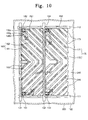
- FIG. 10 is a plan view illustrating a liquid crystal display apparatus according to still yet another embodiment of the present.
- the liquid crystal display apparatus shown in FIG. 10 is similar to the liquid crystal display device shown in FIG. 4, so the following description will be focused on the different parts therebetween in order to avoid redundancy.
- the liquid crystal display apparatus includes substrate 100 and the second substrate 200.
- the pixel areas PA1 and PA2 are defined in substrate 100 and first and second pixel electrodes 160 and 170 are formed in the pixel areas PA1 and PA2.
- the first pixel electrode 160 includes the first main pixel electrode 161 and the first sub-pixel electrode 162
- the second pixel electrode 170 includes the second main pixel electrode 171 and the second sub-pixel electrode 172.
- the second substrate 200 is formed with the common electrode 240 which faces the first and second pixel electrodes 160 and 170.
- the first main pixel electrode 161 is formed with the first area divider 163, and the second main pixel electrode 171 is formed with the second area divider 1 73.
- a third area divider 245 is formed in the common electrode 240. The third area divider 245 is spaced apart from the first and second area dividers 163 and 173 and interacts with the first and second area dividers 163 and 1 73, thereby dividing the pixel areas PA1 and PA2 into a plurality of areas.
- the first, second and third area dividers 163, 173 and 245 can be obtained by cutting predetermined portions of the first and second pixel electrodes 160 and 170 and the common electrode 240, respectively. Such cutting portions may change the electric field between the first and second pixel electrodes 160 and 170 and the common electrode 240, thereby widening the viewing angle of the liquid crystal display device.
- the first, second and third area dividers 163, 173 and 245 can be prepared in the form of protrusions provided on the first and second pixel electrodes 160 and 1 70 and the common electrode 240, respectively.
- FIGS. 11A and 11B are sectional views taken along a line V-V' shown in FIG. 10.
- the liquid crystal layer 300 including liquid crystals is interposed between the first and second substrates 100 and 200.
- the second data line 132 is formed on the gate insulating layer 121 of substrate 100 near the boundary area between the first and second pixel electrodes 160 and 170.
- a light blocking pattern 210 is formed on the second substrate 200 at a position corresponding to the boundary area between the first and second pixel electrodes 160 and 1 70 in order to shield light, except for light introduced into the first and second pixel electrodes 160 and 170.
- the light blocking pattern 210 is formed thereon with a color filter 220, which filters white light having a specific wavelength band so as to provide color images.
- the color filter 220 includes a red filter R, a green filter G and a blue filter (not shown), which are alternately aligned and correspond to three primary colors of light.
- An overcoat layer 230 is formed on the color filter 220 so as to planarize the surface of the second substrate 200 and to protect the color filter 220.
- the common electrode 240 is formed on the overcoat layer 230.
- the common electrode 240 includes a material identical to a material of the pixel electrodes 160 and 170. Predetermined portions of the common electrode 240 are cut so as to form the third area divider 245 to widen the viewing angle of the liquid
- the protective layer 141 and a color filter 148 are formed on the second data line 132 of substrate 100.
- the color filter 148 is used to represent color images.
- the color filter 148 restricts coupling between the second data line 132 and the pixel electrodes 160 and 170, in lieu of the organic layer 146. If the color filter 148 is formed on substrate 100 where the pixel areas PA1 and PA2 are defined, the color filter 148 can be prevented from being misaligned with respect to the pixel areas PA1 and PA2 when fabricating the liquid crystal display device.
- the light blocking pattern 210 is formed on the second substrate 200 and the overcoat layer 230 is formed on the light blocking pattern 210.
- the common electrode 240 is formed on the overcoat layer 230 and protrusions are formed on the common electrode 240 as the third area divider 245 to widen the viewing angle of the liquid crystal display device.
- the viewing angle of the liquid crystal display device can be widened and the operational speed of the liquid crystal display device can be improved.
Landscapes
- Physics & Mathematics (AREA)
- Nonlinear Science (AREA)
- General Physics & Mathematics (AREA)
- Chemical & Material Sciences (AREA)
- Crystallography & Structural Chemistry (AREA)
- Optics & Photonics (AREA)
- Mathematical Physics (AREA)
- Engineering & Computer Science (AREA)
- Spectroscopy & Molecular Physics (AREA)
- Geometry (AREA)
- Computer Hardware Design (AREA)
- Theoretical Computer Science (AREA)
- Liquid Crystal (AREA)
- Electroluminescent Light Sources (AREA)
Abstract
Description
- This application relies for priority upon
Korean Patent Application No. 2006-30646 filed on April 4, 2006 - The present invention relates to a display apparatus having a wide viewing angle and improved operating speed.
- Liquid crystal display devices employ liquid crystals having dielectric and refractive index anisotropy so that the alignment direction of the liquid crystal and the amount of light transmittance is changed in accordance with the applied electric field. However, the image may be distorted when a user views the image from the lateral side of the liquid crystal display device even if the image is properly displayed when the user views the image at the front of the liquid crystal display device. The term "viewing angle" represents the range of angle allowing a user to properly view a displayed image. The liquid crystal display device is generally characterized by a narrow viewing angle compared to CRT displays. It would be advantageous to provide a Liquid crystal display apparatus having a wider viewing angle and better speed of response
- In one aspect of the present invention, a display apparatus includes adjacent first and second pixel areas defined in a first substrate having a first pixel electrode formed in the first pixel area that includes a first main pixel electrode and a first sub-pixel electrode. The second pixel electrode is formed in the second pixel area and includes a second main pixel electrode and a second sub-pixel electrode.
- Adjacent outer contour parts of the first and second pixel electrodes, which face each other, have shapes different from and corresponding to each other, while the area ratio of the first main pixel electrode to the first sub-pixel electrode is identical to the area ratio of the second main pixel electrode to the second sub-pixel electrode.
- A data voltage corresponding to image information is applied to the first and second pixel electrodes. A higher voltage is applied to first sub-pixel electrode than is applied to the first main pixel electrode. A voltage that is higher than the voltage applied to the second main pixel electrode is applied to the second sub-pixel electrode. The optical characteristics of the device are compensated by the application of the high and low voltages so as to widen the viewing angle. In addition, the size of areas in the first and second pixel electrodes receiving the high voltage is identical to the size of areas receiving the low voltage, the first and second pixel electrodes display images having superior quality.
- The foregoing and other objects, features and advantages of the present invention will become readily apparent from a reading of the ensuing description together with the drawing, in which:
- FIG. 1 is a plan view illustrating a liquid crystal display apparatus according to an exemplary embodiment of the present invention;
- FIG. 2 is a sectional view taken along a line I-I' shown in FIG. 1;
- FIG. 3 is an enlarged view of "A" shown in FIG. 1;
- FIG. 4 is a plan view illustrating a liquid crystal display apparatus according to another embodiment of the present invention;
- FIG. 5 is a sectional view taken along a line II-II' shown in FIG. 4;
- FIG. 6 is a plan view illustrating a liquid crystal display apparatus according to still another embodiment of the present;
- FIG. 7 is a sectional view taken along a line III-III' shown in FIG. 6;
- FIGS. 8A and 8B are plan views illustrating liquid crystal display apparatuses according to still yet another embodiment of the present invention;
- FIG. 9 is a sectional view taken along a line IV-IV' shown in FIG. 8A;
- FIG. 10 is a plan view illustrating a liquid crystal display apparatus according to still yet another embodiment of the present; and
- FIGS. 11A and 11B are sectional views taken along a line V-V' shown in FIG. 10.
- Referring to FIG. 1, the liquid crystal display apparatus includes a
first substrate 100, on which pixel areas PA1 and PA2 are defined, andpixel electrodes substrate 100. In addition, a second substrate (not shown) facingsubstrate 100 is prepared and a liquid crystal layer (not shown) having liquid crystals is interposed betweensubstrate 100 and the second substrate. Thepixel electrodes first pixel electrode 160 and asecond pixel electrode 1 70 having different shapes. Pixel areas PA1 and PA2 are basic areas that represent an image and have rectangular shapes with length and breadth in a ratio of 1 :3. - First and
second pixel electrodes second pixel electrodes main pixel electrode sub-pixel electrode first pixel electrode 160 is divided into the firstmain pixel electrode 161 and thefirst sub-pixel electrode 162, and thesecond pixel electrode 170 is divided into the secondmain pixel electrode 1 71 and thesecond sub-pixel electrode 172.Main pixel electrodes sub-pixel electrodes sub-pixel electrodes main pixel electrodes sub-pixel electrodes - For instance, voltages having various levels can be individually applied to
main pixel electrodes sub-pixel electrodes pixel electrodes main pixel electrode 161 and thefirst sub-pixel electrode 162 of the first pixel area PA1 is adjusted to compensate optical properties betweenpixel electrode 161 andsub-pixel electrode 162 to improve viewing the angle of the liquid crystal display device in the first pixel area PA. - At the high gray scale, light transmittance is gradually reduced from the center to the lateral side of the liquid crystal display device thereby narrowing the viewing angle. However, the viewing angle of the liquid crystal display device can be widened at the high gray scale by applying different voltages to the first
main pixel electrode 161 and thefirst sub-pixel electrode 162 based on the voltage-transmittance characteristics of the firstmain pixel electrode 161 and thefirst sub-pixel electrode 162. Such an increase of the viewing angle is also applicable for thesecond pixel electrode 170. - A
first area divider 163 is formed in the firstmain pixel electrode 161 to dividepixel electrode 161 into a plurality of areas. Thefirst area divider 163 includes notches which are obtained by cutting predetermined portions of the firstmain pixel electrode 161. In the same way, a boundary area can be formed betweenpixel electrode 161 andsub-pixel electrode 162 by cutting a predetermined portion of thefirst pixel electrode 160. If the number of the areas obtained by dividing the firstmain pixel electrode 161 is N, thefirst pixel electrode 160 including thefirst sub-pixel electrode 162 is divided into (N+1) areas. Similarly, asecond area divider 173 is formed in the secondmain pixel electrode 1 71, so that thesecond pixel electrode 1 71 includes a plurality of areas, which are obtained by dividing the secondmain pixel electrode 171, and thesecond sub-pixel electrode 172. - FIG. 2 is a sectional view taken along a line I-I' shown in FIG. 1. Referring to FIG. 2,
pixel electrode 160 includingmain pixel electrode 161 andsub-pixel electrode 162 is formed onsubstrate 100. A data voltage is applied to thefirst pixel electrode 160 according to display information, and a predetermined common voltage is applied to a second substrate 200 (dotted line) facingsubstrate 100. An electric field (E) is generated due to the potential difference between the data voltage and the common voltage. The electric field (E) is applied toliquid crystals 310 aligned between the first andsecond substrates - The electric field (E) is created vertically to
main pixel electrode 161 andsub-pixel electrode 162. The electric field (E) is tilted in the boundary area betweenpixel electrode 161 andsub-pixel electrode 162. If theliquid crystals 310 have negative dielectric anisotropy, theliquid crystals 310 are tilted vertically to the direction of the electric field (E). - As shown in FIG. 2, at the boundary area between the first
main pixel electrode 161 and the firstsub-pixel electrode 162 theliquid crystals 310 are tilted in different directions according to the electric field (E). Theliquid crystals 310 are also tilted in different directions at boundaries between areas defined byarea divider 173. The optical characteristics of each area may vary depending on the alignment direction of theliquid crystals 310. If theliquid crystals 310 are properly aligned to compensate for the optical characteristics between the areas, the operational characteristics of the liquid crystal display device can be improved. Such an effect is also applicable for thesecond pixel electrode 1 70. - FIG. 3 is an enlarged view of "A" shown in FIG. 1. Referring to FIG. 3, the first and
second pixel electrodes second pixel electrodes first pixel electrode 160 may face the long and short lateral sides of thesecond pixel electrode 170, respectively. In this case, the operational characteristics of the liquid crystal display device can be improved as follows: - An inverse driving scheme can be employed when the voltage is applied to the first and
second pixel electrodes second pixel electrodes first pixel electrode 160 and a negative voltage is applied to thesecond pixel electrode 170 during a specific frame, the polarity of the voltages are reversed during the next frame. According to the inverse driving scheme, the alignment direction of theliquid crystals 310 is changed in the left or right direction as the frame is changed. That is, theliquid crystals 310 are prevented from being continuously aligned in the same direction, thereby preventing performance degradation of the liquid crystal display. Even if the inverse driving scheme is not employed, different voltages can be applied to the first andsecond pixel electrodes - In this manner, when the different voltages are applied to the first and
second pixel electrodes second pixel electrodes second pixel electrodes second substrates - The direction of the lateral electric field (Ef) is changed according to the shape of the first and
second pixel electrodes first pixel electrode 160 corresponds to the shape of thesecond pixel electrode 160, the direction of the lateral electric field (Ef) may match with the direction of the electric field applied to theliquid crystals 310 in the first orsecond pixel electrode - For instance, the length direction of the notches in the
first pixel electrode 160 may match with the extension direction of the saw-tooth shaped long lateral sides of the first andsecond pixel electrodes liquid crystals 310, the crystals located at the outer contour part of thefirst pixel electrode 160 are rapidly aligned in the direction identical to the alignment direction of the liquid crystals controlled by the middle of thefirst pixel electrode 160,thereby improving operational speed. In the same way, the liquid crystals existing at the outer contour part of thesecond pixel electrode 170 can be rapidly aligned when the electric field is applied thereto, so that the operational speed of the liquid crystal display device may be further improved. - In addition to the outer contour parts of the adjacent first and
second pixel electrodes second pixel electrodes substrate 100 by turns, all outer contour parts of the adjacent first andsecond pixel electrodes second pixel electrodes second pixel electrodes second pixel electrodes - If the outer contour parts of the first and
second pixel electrodes first pixel electrode 160 is different from that of thesecond pixel electrode 170. In this case, the shape of the firstmain pixel electrode 161 is different from that of the secondmain pixel electrode 1 71 and the shape of the firstsub-pixel electrode 162 is different from that of the secondsub-pixel electrode 172. Nevertheless, the area ratio of themain pixel electrode 161 to thesub-pixel electrode 162 in thefirst pixel electrode 160 is equal to or approximate to the area ratio of themain pixel electrode 1 71 to thesub-pixel electrode 1 72 in thesecond pixel electrode 170. - In this case, the optical compensation between the first
main pixel electrode 161 and the firstsub-pixel electrode 162 of thefirst pixel electrode 160 is identical to the optical compensation between the secondmain pixel electrode 1 71 and the secondsub-pixel electrode 1 72 of thesecond pixel electrode 170. Accordingly, the first andsecond pixel electrodes - Preferably, the area ratio is within a range between 1:1 and 3:1. More preferably; the area ratio is 2:1. The area ratio may vary depending on the alignment between
main pixel electrodes sub-pixel electrodes main pixel electrodes - Referring again to FIG. 1, the first
sub-pixel electrode 162 has a size larger than that of any area defined in the firstmain pixel electrode 161. In order to allow the firstsub-pixel electrode 162 to have the large size, the firstsub-pixel electrode 162 is inclined from one edge of one long lateral side of the first pixel area PA1 to the center of the other long lateral side of the first pixel area PA1 having a rectangular shape. The divided areas constituting the firstmain pixel electrode 161 are separately aligned while interposing the firstsub-pixel electrode 162 therebetween, in such a manner that the divided areas can be connected to each other at abridge 10 formed in the longitudinal direction. - The second
sub-pixel electrode 172 is inclined from one edge of one long lateral side of the second pixel area PA2 to the center of the other long lateral side of the second pixel area PA2 having a rectangular shape. In addition, the divided areas constituting the secondmain pixel electrode 171 are separately aligned while interposing the secondsub-pixel electrode 1 72 therebetween. The firstsub-pixel electrode 162 and thefirst area divider 163 are offset from the secondsub-pixel electrode 1 72 and thesecond area divider 173 in such a manner that adjacent outer contour parts of the first and second pixel electrodes have the saw-tooth shape. - FIG. 4 is a plan view illustrating a liquid crystal display apparatus according to another embodiment of the present invention. Referring to FIG. 4,
gate lines data lines substrate 100 such thatgate lines data lines Gate lines main gate line 111 and asub-gate line 112, anddata lines first data line 131 and asecond data line 132. Themain gate line 111, thesub-gate line 112 and thefirst data line 131 may define the first pixel area PA1, and themain gate line 111, thesub-gate line 112 and thesecond data line 132 may define the second pixel area PA2. - The first and second pixel areas PA1 and PA2 constitute the pixel areas PA1 and PA2. Although a plurality of pixel areas PA1 and PA2 are repeatedly defined in
substrate 100 by means ofgate lines data lines - The
first pixel electrode 160 is formed in the first pixel area PA1 and thesecond pixel electrode 170 is formed in the second pixel area PA2. Thefirst pixel electrode 160 includesmain pixel electrode 161 andsub-pixel electrode 162, and thesecond pixel electrode 170 includesmain pixel electrode 171 andsub-pixel electrode 172.Pixel electrode 160 is provided with a mainthin film transistor 151 and asub-thin film transistor 152, and thesecond pixel electrode 170 is provided with a mainthin film transistor 153 and asub-thin film transistor 1 54. - The
thin film transistors 1 51 to 1 54 include agate electrode 110g, asource electrode 130s, and adrain electrode 130d, respectively. In the first mainthin film transistor 1 51, thegate electrode 110g branches from themain gate line 111, thesource electrode 130s branches from thefirst data line 131, and thedrain electrode 130d is electrically connected to the firstmain pixel electrode 161. In the firstsub-thin film transistor 152, thegate electrode 110g branches from thesub-gate line 112, thesource electrode 130s branches from thefirst data line 131, and thedrain electrode 130d is electrically connected to the firstsub-pixel electrode 162. - During the operation of the liquid crystal display device, a gate-on signal is applied to the
main gate line 111 and thesub-gate line 112, so that the first mainthin film transistor 151 and the firstsub-thin film transistor 152 are turned on. Then, a data signal corresponding to image information is applied to thefirst data line 131, and the data voltage is applied to the firstmain pixel electrode 161 and the firstsub-pixel electrode 162. At this time, different gate-on signals are applied to first mainthin film transistor 151 and the firstsub-thin film transistor 152, respectively, so that a low voltage is applied to the firstmain pixel electrode 161 and a high voltage is applied to the firstsub-pixel electrode 162. - In the second main
thin film transistor 1 53, thegate electrode 110g branches from themain gate line 111, thesource electrode 130s branches from thesecond data line 132, and thedrain electrode 130d is electrically connected to the secondmain pixel electrode 171. In the secondsub-thin film transistor 1 54, thegate electrode 110g branches from thesub-gate line 112, thesource electrode 1 30s branches from thesecond data line 132, and thedrain electrode 130d is electrically connected to the secondsub-pixel electrode 172. Thesecond pixel electrode 1 70 also operates in the same manner as thefirst pixel electrode 160. - FIG. 5 is a sectional view taken along a line II-II' shown in FIG. 4.
- Referring to FIG. 5, the
gate electrode 110g is formed onsubstrate 100.Gate electrode 110g may be prepared in the form of a single layer pattern including any one selected from the group consisting of aluminum based metal, silver based metal, copper based metal, molybdenum based metal, chrome, titanium and tantalum. Alternatively,gate electrode 110g may be in the form of a multi-layer pattern including plural materials, which are selected from the above metals having physical properties different from each other. - A
gate insulating layer 121 is formed on thegate electrode 110g such that thegate insulating layer 121 covers the entire surface ofsubstrate 100. Thegate insulating layer 121 includes a transparent inorganic layer having a silicon nitride material and insulates thegate electrode 110g from thesource electrode 130s and thedrain electrode 1 30d. - A
semiconductor pattern 1 22 is formed on thegate insulating layer 121 such that thesemiconductor pattern 122 can be overlapped with thegate electrode 110g. Thesemiconductor pattern 122 is a dual-layer pattern consisting of anactive pattern 123 and anohmic contact pattern 124 and is obtained by depositing a hydrogenated amorphous silicon layer on the entire surface ofsubstrate 100 and then patterning the hydrogenated amorphous silicon layer. A channel is formed in theactive pattern 123 during the operation of the liquid crystal display device. Theohmic contact pattern 124 includes a hydrogenated amorphous silicon layer pattern doped with n-type impurity ions and is divided into two parts, which face each other on thegate electrode 110g. - The
source electrode 1 30s and thedrain electrode 130d are formed on thesemiconductor pattern 122. The source electrode 130s is spaced apart from thedrain electrode 130d in such a manner that thesource electrode 130s faces thedrain electrode 130d on thegate electrode 110g. Similar to thegate electrode 110g, thesource electrode 130s and thedrain electrode 130d are prepared in the form of single layer patterns including one selected from various metals or multi-layer patterns including plural materials having physical properties different from each other. - A
protective layer 141 is formed on thesource electrode 130s and thedrain electrode 130d. Theprotective layer 141 includes a transparent inorganic layer having silicon nitride and anorganic layer 146 is formed on theprotective layer 141. Theorganic layer 146 includes a transparent material having a low dielectric constant and is formed with a large thickness. Theprotective layer 141 and theorganic layer 146 are formed with acontact hole 145h, which exposes a predetermined region of thedrain electrode 130d. - The
pixel electrodes organic layer 146. Thepixel electrodes first pixel electrode 160 electrically connected to thedrain electrode 130d through thecontact hole 145h. Thesecond data line 132 is formed on thegate insulating layer 121 in such a manner that thesecond data line 132 can be overlapped with the first andsecond pixel electrodes - The first and
second pixel electrodes second data line 132 such that thefirst pixel electrode 160 is adjacent to thesecond pixel electrode 1 70 as close as possible. This is advantageous in that a strong fringe field can be generated between the first andsecond pixel electrodes second data line 132 is strongly coupled with the first andsecond pixel electrodes second data line 132. According to the exemplary embodiment of the present invention, strong coupling between the second data line and the pixel electrodes can be prevented by a thickorganic layer 146 having low dielectric constant permittingfirst pixel electrode 160 to be positioned closely adjacent to thesecond pixel electrode 1 70. - FIG. 6 is a plan view illustrating a liquid crystal display apparatus according to still another embodiment of the present.
- Referring to FIG. 6,
gate lines 110 anddata lines substrate 100 such that thegate lines 110 are insulated from thedata lines 1 33 and 136 while crossing thedata lines 1 33 and 136. The data lines 133 and 136 include afirst data line 133 and asecond data line 136. Thefirst data line 1 33 includes a firstmain data line 134 and a firstsub-data line 1 35, and thesecond data line 1 36 includes a secondmain data line 137 and a secondsub-data line 138. Thegate line 110, the firstmain data line 134 and the firstsub-data line 135 may define the first pixel area PAI. In addition, thegate line 110, a secondmain data line 137 and the secondsub-data line 138 may define the second pixel area PA2. - The first and second pixel areas PA1 and PA2 constitute the pixel areas PA1 and PA2. Although a plurality of pixel areas PA1 and PA2 are repeatedly defined in
substrate 100 by means of thegate lines 110 anddata lines - The
first pixel electrode 160 is formed in the first pixel area PA1 and thesecond pixel electrode 170 is formed in the second pixel area PA2. Thefirst pixel electrode 160 includes the firstmain pixel electrode 161 and the firstsub-pixel electrode 162, and thesecond pixel electrode 170 includes the secondmain pixel electrode 1 71 and the secondsub-pixel electrode 172. Thefirst pixel electrode 160 is provided with a first mainthin film transistor 156 and a firstsub-thin film transistor 157, and thesecond pixel electrode 170 is provided with a second mainthin film transistor 158 and a secondsub-thin film transistor 1 59. - The
thin film transistors 156 to 1 59 include agate electrode 110g, asource electrode 130s, and adrain electrode 130d, respectively. In the first mainthin film transistor 156, thegate electrode 110g branches from themain gate line 110, thesource electrode 130s branches from the firstmain data line 134, and thedrain electrode 130d is electrically connected to the firstmain pixel electrode 161. In the firstsub-thin film transistor 1 57, thegate electrode 110g branches from thegate line 110, thesource electrode 130s branches from the firstsub-data line 135, and thedrain electrode 1 30d is electrically connected to the firstsub-pixel electrode 162. - During the operation of the liquid crystal display device, a gate-on signal is transmitted to the
gate line 110, so that the first mainthin film transistor 1 56 and the firstsub-thin film transistor 1 57 are turned on. Then, a data signal corresponding to image information is transmitted to thefirst data line 133. In addition, a low voltage is applied to the firstmain pixel electrode 161 through the firstmain data line 134, and a high voltage is applied to the firstsub-pixel electrode 162 through the firstsub-data line 135. - In the second main
thin film transistor 1 58, thegate electrode 110g branches from themain gate line 110, thesource electrode 130s branches from the secondmain data line 137, and thedrain electrode 130d is electrically connected to the secondmain pixel electrode 171. In the secondsub-thin film transistor 1 59, thegate electrode 110g branches from thegate line 110, thesource electrode 130s branches from the secondsub-data line 138, and thedrain electrode 130d is electrically connected to the secondsub-pixel electrode 172. Thesecond pixel electrode 1 70 also operates in the same manner as thefirst pixel electrode 160. - FIG. 7 is a sectional view taken along a line III-III' shown in FIG. 6.
- Referring to FIG. 7, the
gate electrode 110g, thesource electrode 1 30s and thedrain electrode 1 30d of the first mainthin film transistor 156 are formed on a predetermined area ofsubstrate 100. Thedrain electrode 130d of the firstsub-thin film transistor 157 is formed while being spaced apart from the first mainthin film transistor 1 56. In addition, the firstsub-data line 1 35 is aligned in parallel to the secondmain data line 137. Thefirst pixel electrode 160 is formed on the firstsub-data line 135 and thesecond pixel electrode 170 is formed on the secondmain data line 137. - FIG. 8A is a plan view illustrating a liquid crystal display apparatus according to still yet another embodiment of the present invention. The liquid crystal display apparatus shown in FIG. 8A is similar to the liquid crystal display device shown in FIG. 4, so the following description will be focused on the different parts therebetween in order to avoid redundancy.
- Referring to FIG. 8A, a
first storage electrode 114 is formed betweensubstrate 100 and thefirst pixel electrode 160, and asecond storage electrode 117 is formed betweensubstrate 100 and thesecond pixel electrode 1 70. Thefirst storage electrode 114 is partially overlapped with the firstmain pixel electrode 161 and the firstsub-pixel electrode 162. Hereinafter, the part of thefirst storage electrode 114, which overlap the firstmain pixel electrode 161 will be referred to as a "firstmain storage electrode 115", and the part of thefirst storage electrode 114 which overlaps the firstsub-pixel electrode 162 will be referred to as a "firstsub-storage electrode 116". - The
first storage electrode 114 overlaps thefirst pixel electrode 160, thereby forming a first storage capacitor. The first storage capacitor maintains the data signal applied to thefirst pixel electrode 160 for a predetermined period of time. Thefirst storage electrode 114 includes a light blocking material, such as copper or aluminum, which is identical to a material of thegate electrode 1 10g, and is formed simultaneously with thegate electrode 110g. The rest of thefirst pixel electrode 160 area not covered by the light blocking material serves to display an image. The structure, function and material of thefirst storage electrode 114 are substantially similar to those of thesecond storage electrode 117. - The aperture ratio of
main pixel electrodes sub-pixel electrodes second storage electrodes main pixel electrodes sub-pixel electrodes second pixel electrodes main pixel electrodes sub-pixel electrodes - In FIG. 8A, when drawing a virtual line that transversely bisects the first and
second pixel electrodes main storage electrode 115 and the secondmain storage electrode 118 are provided along the virtual line with rectangular shapes. In addition, the firstmain pixel electrode 161 has an area larger than that of the secondmain pixel electrode 171 when viewed in the lengthwise direction of the virtual line. Accordingly, if the firstmain storage electrode 115 has a width smaller than that of the secondmain storage electrode 118 in the direction vertical to the lengthwise direction of the virtual line, the firstmain storage electrode 115 has an area identical to that of the secondmain storage electrode 118. - A second
sub-storage electrode 119 is formed along the virtual line with a rectangular shape. The firstsub-pixel electrode 162 has a very small area when viewed in the lengthwise direction of the virtual line. Therefore, the firstsub-storage electrode 116 may not have sufficient area corresponding to the area of the secondsub-storage electrode 119. Accordingly, the firstsub-storage electrode 116 must branch from the firstmain storage electrode 115 in both directions vertical to the virtual line. The length of the branch part of the firstsub-storage electrode 116 is properly adjusted in such a manner that the firstsub-storage electrode 116 has an area identical to that of the secondsub-storage electrode 119. - In this manner, if the areas of the first and second
main storage electrodes sub-storage electrodes main pixel electrode 161 and the firstsub-pixel electrode 162 become the same as the aperture ratios of the secondmain pixel electrode 171 and the secondsub-pixel electrode 172. - FIG. 8B is a plan view illustrating a liquid crystal display apparatus according to still yet another embodiment of the present invention. The liquid crystal display apparatus shown in FIG. 8B is partially identical to the liquid crystal display device shown in FIG. 8A, so the following description will be focused on the different parts therebetween in order to avoid redundancy.
- Referring to FIG. 8B, the first
sub-storage electrode 116 primarily branches from the first main storage electrode 11 5 in a direction vertical to the firstmain storage electrode 115. In this state, both end portions of the firstsub-storage electrode 116 secondarily extend lengthwise along the firstmain storage electrode 115. Such a dual-branch structure of the firstsub-storage electrode 116 is necessary when the firstsub-storage electrode 116, which branches from the firstmain storage electrode 115, has no sufficient area corresponding to the secondsub-storage electrode 119. - In addition to the embodiments shown in FIGS. 8A and 8B, various shapes or configurations can be provided in order to allow the
first storage electrode 114 to have an area ratio identical to that of thesecond storage electrode 117. Hereinafter, description will be made in relation to the sectional structure of the liquid crystal display device having the first andsecond storage electrode - FIG. 9 is a sectional view taken along a line IV-IV' shown in FIG. 8A.
- Referring to FIG. 9, the
gate electrode 110g and thefirst storage electrode 114, which is spaced apart from thegate electrode 110g, are formed onsubstrate 100. Thegate electrode 110g and thefirst storage electrode 114 are covered with thegate insulating layer 121. Thesemiconductor pattern 122, thesource electrode 130s and thedrain electrode 130d are formed on the insulatinglayer 121 covering thegate electrode 110g. In addition, the protective layer and theorganic layer 146 are formed on thesource electrode 1 30s and thedrain electrode 130d. - The
first storage electrode 114 vertically faces thefirst pixel electrode 160, and thegate insulating layer 121, theprotective layer 141 and theorganic layer 146 are interposed between thefirst storage electrode 114 and thefirst pixel electrode 160. As a result, the first storage capacitor is formed. The capacitance of the first storage capacitor may vary depending on the distance between thefirst storage electrode 114 and thefirst pixel electrode 160 and the dielectric constant of thegate insulating layer 121, theprotective layer 141 and theorganic layer 146 interposed between thefirst storage electrode 114 and thefirst pixel electrode 160. In order to increase the capacitance of the first storage capacitor by reducing the distance between thefirst storage electrode 114 and thefirst pixel electrode 160, a predetermined area of theorganic layer 146 is opened and thefirst pixel electrode 160 is inserted into the opening section of theorganic layer 146. - FIG. 10 is a plan view illustrating a liquid crystal display apparatus according to still yet another embodiment of the present. The liquid crystal display apparatus shown in FIG. 10 is similar to the liquid crystal display device shown in FIG. 4, so the following description will be focused on the different parts therebetween in order to avoid redundancy.
- Referring to FIG. 10, the liquid crystal display apparatus includes
substrate 100 and thesecond substrate 200. The pixel areas PA1 and PA2 are defined insubstrate 100 and first andsecond pixel electrodes first pixel electrode 160 includes the firstmain pixel electrode 161 and the firstsub-pixel electrode 162, and thesecond pixel electrode 170 includes the secondmain pixel electrode 171 and the secondsub-pixel electrode 172. Thesecond substrate 200 is formed with thecommon electrode 240 which faces the first andsecond pixel electrodes - The first
main pixel electrode 161 is formed with thefirst area divider 163, and the secondmain pixel electrode 171 is formed with thesecond area divider 1 73. Athird area divider 245 is formed in thecommon electrode 240. Thethird area divider 245 is spaced apart from the first andsecond area dividers second area dividers - The first, second and
third area dividers second pixel electrodes common electrode 240, respectively. Such cutting portions may change the electric field between the first andsecond pixel electrodes common electrode 240, thereby widening the viewing angle of the liquid crystal display device. The first, second andthird area dividers second pixel electrodes common electrode 240, respectively. - FIGS. 11A and 11B are sectional views taken along a line V-V' shown in FIG. 10.
- Referring to FIG. 11A, the
liquid crystal layer 300 including liquid crystals is interposed between the first andsecond substrates second data line 132 is formed on thegate insulating layer 121 ofsubstrate 100 near the boundary area between the first andsecond pixel electrodes - A
light blocking pattern 210 is formed on thesecond substrate 200 at a position corresponding to the boundary area between the first andsecond pixel electrodes second pixel electrodes light blocking pattern 210 is formed thereon with acolor filter 220, which filters white light having a specific wavelength band so as to provide color images. Thecolor filter 220 includes a red filter R, a green filter G and a blue filter (not shown), which are alternately aligned and correspond to three primary colors of light. Anovercoat layer 230 is formed on thecolor filter 220 so as to planarize the surface of thesecond substrate 200 and to protect thecolor filter 220. Thecommon electrode 240 is formed on theovercoat layer 230. Thecommon electrode 240 includes a material identical to a material of thepixel electrodes common electrode 240 are cut so as to form thethird area divider 245 to widen the viewing angle of the liquid crystal display device. - Referring to FIG. 11B, the
protective layer 141 and acolor filter 148 are formed on thesecond data line 132 ofsubstrate 100. Thecolor filter 148 is used to represent color images. In addition, thecolor filter 148 restricts coupling between thesecond data line 132 and thepixel electrodes organic layer 146. If thecolor filter 148 is formed onsubstrate 100 where the pixel areas PA1 and PA2 are defined, thecolor filter 148 can be prevented from being misaligned with respect to the pixel areas PA1 and PA2 when fabricating the liquid crystal display device. - According to another embodiment of the present invention, the
light blocking pattern 210 is formed on thesecond substrate 200 and theovercoat layer 230 is formed on thelight blocking pattern 210. In addition, thecommon electrode 240 is formed on theovercoat layer 230 and protrusions are formed on thecommon electrode 240 as thethird area divider 245 to widen the viewing angle of the liquid crystal display device. - As described above, according to the present invention, the viewing angle of the liquid crystal display device can be widened and the operational speed of the liquid crystal display device can be improved.
- Although the exemplary embodiments of the present invention have been described, it is understood that the present invention should not be limited to these exemplary embodiments but various changes and modifications can be made by one ordinary skilled in the art within the spirit and scope of the present invention as hereinafter claimed.
Claims (24)
- A display apparatus comprising:a first substrate having adjacent first and second pixel areas;a main and a sub-pixel electrode formed in each of the first and second pixel areas; andthe pixel electrodes of the first and second pixel areas having adjacent outer contour parts facing each other, an area ratio of the main pixel electrode to the sub-pixel electrode of the first pixel area being the same as an area ratio of the main pixel electrode to the sub-pixel electrode of the second pixel area.
- The display apparatus of claim 1, wherein the area ratio is within a range of 1:1 to 3:1.
- The display apparatus of claim 1, further comprising a first area divider dividing the first main pixel electrode in the first pixel area into a plurality of areas, and a second area divider dividing the second main pixel electrode in the second pixel area into a plurality of areas.
- The display apparatus of claim 3, wherein the area ratio is 2:1.
- The display apparatus of claim 3, wherein the first and second area dividers include notches, which are formed by cutting predetermined areas of the first and second main pixel electrodes.
- The display apparatus of claim 5, wherein the notches include a first portion extending vertically to a boundary area between the first and second pixel areas, and a second portion tilted with respect to the boundary area.
- The display apparatus of claim 3, wherein the adjacent outer contour parts of the first and second pixel electrodes have saw-tooth shapes which engage with each other.
- The display apparatus of claim 7, wherein other first and second pixel electrodes having saw-tooth shapes are interposed between the facing outer contour parts such that the first pixel electrode engages with the second pixel electrode.
- The display apparatus of claim 1, wherein a data voltage corresponding to image information is applied to the first and second pixel electrodes, a voltage which is higher than a voltage applied to the first main pixel electrode is applied to the first sub-pixel electrode, and a voltage which is higher than a voltage applied to the second main pixel electrode is applied to the second sub-pixel electrode.
- The display apparatus of claim 1, further comprising a first storage electrode formed between the first substrate and the first pixel electrode in the first pixel area, and a second storage electrode having a shape different from that of the first storage electrode and being formed between the first substrate and the second pixel electrode in the second pixel area.
- The display apparatus of claim 10, wherein the first storage electrode includes a first main storage electrode, which is overlapped with the first main pixel electrode, a first sub-storage electrode, which is overlapped with the first sub-pixel electrode, and the second storage electrode includes a second main storage electrode, which is overlapped with the second main pixel electrode, a second sub-storage electrode, which is overlapped with the second sub-pixel electrode.
- The display apparatus of claim 11, wherein an area ratio of the first main storage electrode to the first sub-storage electrode is identical to an area ratio of the second main storage electrode to the second sub-storage electrode.
- The display apparatus of claim 12, wherein the first sub-storage electrode vertically branches from the first main storage electrode, and the second storage electrode extends lengthwise along the first main storage electrode.
- The display apparatus of claim 12, wherein the first sub-storage electrode vertically branches from the first main storage electrode, in which both end portions of the first sub-storage electrode secondarily extend lengthwise along the first sub-storage electrode, and the second storage electrode extends lengthwise along the first main storage electrode.
- The display apparatus of claim 1, further comprising a gate line and a data line formed on the first substrate so as to define the pixel areas.
- The display apparatus of claim 15, wherein outer contour parts of the first and second pixel electrodes, which adjacent to each other, are overlapped with each other on the data line.
- The display apparatus of claim 16, further comprising an organic layer interposed between the data line and the first and second pixel electrodes in the first and second pixel areas.
- The display apparatus of claim 16, further comprising a color filter interposed between the data line and the first and second pixel electrodes.
- The display apparatus of claim 15, wherein the gate line includes a main gate line and a sub-gate line, which face each other while interposing the pixel electrodes therebetween, the data line includes a first data line and a second data line, which face each other while interposing the first pixel electrode therebetween, and
the display apparatus further comprises a first main thin film transistor connected to the main gate line, the first data line and the first main pixel electrode, a first sub-thin film transistor connected to the sub-gate line, the first data line and the first sub-pixel electrode, a second main thin film transistor connected to the main gate line, the second data line and the second main pixel electrode, and a second sub-thin film transistor connected to the sub-gate line, the second data line and the second sub-pixel electrode. - The display apparatus of claim 15, wherein the data line includes a first main data line and a first sub-data line, which face each other while interposing the first pixel electrode therebetween, and a second main data line and a second sub-data line, which face each other while interposing the second pixel electrode therebetween, and
the display apparatus further comprises a first main thin film transistor connected to the gate line, the first main data line and the first main pixel electrode, a first sub-thin film transistor connected to the gate line, the first sub-data line and the first sub-pixel electrode, a second main thin film transistor connected to the gate line, the second main data line and the second main pixel electrode, and a second sub-thin film transistor connected to the gate line, the second sub-data line and the second sub-pixel electrode. - The display apparatus of claim 1, further comprising a second substrate coupled with the first substrate and a common electrode formed on the second substrate while facing the first and second pixel electrodes in the first and second pixel areas.
- The display apparatus of claim 21, further comprising first and second area dividers formed on the first and second main pixel electrodes, respectively, and a third area divider formed on the common electrode while being spaced apart from the first and second area dividers, wherein the third area divider interacts with the first and second area dividers so as to divide the pixel areas into a plurality of areas.
- The display apparatus of claim 22, wherein the first and second area dividers include notches, which are formed by cutting predetermined areas of the first and second main pixel electrodes, and the third area divider includes notches formed by cutting predetermined areas of the common electrode.
- The display apparatus of claim 22, wherein the first and second area dividers include notches, which are formed by cutting predetermined areas of the first and second main pixel electrodes, and the third area divider includes protrusions formed on predetermined areas of the common electrode.
Applications Claiming Priority (1)
| Application Number | Priority Date | Filing Date | Title |
|---|---|---|---|
| KR1020060030646A KR101257380B1 (en) | 2006-04-04 | 2006-04-04 | Display Apparatus |
Publications (3)
| Publication Number | Publication Date |
|---|---|
| EP1843195A2 true EP1843195A2 (en) | 2007-10-10 |
| EP1843195A3 EP1843195A3 (en) | 2010-10-27 |
| EP1843195B1 EP1843195B1 (en) | 2013-07-31 |
Family
ID=38219536
Family Applications (1)
| Application Number | Title | Priority Date | Filing Date |
|---|---|---|---|
| EP07006154.4A Active EP1843195B1 (en) | 2006-04-04 | 2007-03-26 | Display apparatus |
Country Status (4)
| Country | Link |
|---|---|
| US (1) | US7852418B2 (en) |
| EP (1) | EP1843195B1 (en) |
| KR (1) | KR101257380B1 (en) |
| CN (1) | CN101051132B (en) |
Families Citing this family (9)
| Publication number | Priority date | Publication date | Assignee | Title |
|---|---|---|---|---|
| KR101189267B1 (en) * | 2004-12-03 | 2012-10-09 | 삼성디스플레이 주식회사 | A thin film transistor array panel and a liquid crystal display |
| KR101309552B1 (en) * | 2006-11-01 | 2013-09-23 | 삼성디스플레이 주식회사 | Array substrate and display panel having the same |
| KR20090131842A (en) * | 2008-06-19 | 2009-12-30 | 삼성전자주식회사 | Liquid crystal display |
| KR101521516B1 (en) * | 2008-11-18 | 2015-05-19 | 삼성디스플레이 주식회사 | Liquid crystal display apparatus |
| KR101641538B1 (en) * | 2008-12-24 | 2016-07-22 | 삼성디스플레이 주식회사 | Display panel |
| KR102396288B1 (en) * | 2014-10-27 | 2022-05-10 | 삼성디스플레이 주식회사 | Organic light emitting diode display device |
| KR20160061536A (en) * | 2014-11-21 | 2016-06-01 | 삼성디스플레이 주식회사 | Liquid display device |
| CN104597647B (en) * | 2015-01-21 | 2017-11-28 | 深圳市华星光电技术有限公司 | A kind of liquid crystal display panel and preparation method thereof |
| CN106483727B (en) * | 2016-12-28 | 2019-07-12 | 深圳市华星光电技术有限公司 | Liquid crystal display panel, array substrate and its dot structure with balance farmland area |
Citations (2)
| Publication number | Priority date | Publication date | Assignee | Title |
|---|---|---|---|---|
| US6335778B1 (en) * | 1996-08-28 | 2002-01-01 | Sharp Kabushiki Kaisha | Active matrix type liquid crystal display device using driver circuits which latch-in data during horizontal blanking period |
| US20050036091A1 (en) * | 2003-08-13 | 2005-02-17 | Song Jang-Kun | Liquid crystal display and panel therefor |
Family Cites Families (12)
| Publication number | Priority date | Publication date | Assignee | Title |
|---|---|---|---|---|
| US5610739A (en) * | 1994-05-31 | 1997-03-11 | Matsushita Electric Industrial Co., Ltd. | Liquid crystal display unit with a plurality of subpixels |
| KR100218584B1 (en) * | 1994-09-21 | 1999-09-01 | 모리시타 요이찌 | Liquid crystal display device and driving method thereof |
| JP3062090B2 (en) * | 1996-07-19 | 2000-07-10 | 日本電気株式会社 | Liquid crystal display |
| JP3383205B2 (en) * | 1997-12-26 | 2003-03-04 | シャープ株式会社 | LCD panel |
| TW583425B (en) * | 2001-08-02 | 2004-04-11 | Sanyo Electric Co | Liquid crystal display |
| US7209192B2 (en) * | 2001-09-26 | 2007-04-24 | Samsung Electronics Co., Ltd. | Thin film transistor array panel for liquid crystal display and method for manufacturing the same |
| US7492379B2 (en) * | 2002-01-07 | 2009-02-17 | Samsung Electronics Co., Ltd. | Color flat panel display sub-pixel arrangements and layouts for sub-pixel rendering with increased modulation transfer function response |
| JP4342200B2 (en) * | 2002-06-06 | 2009-10-14 | シャープ株式会社 | Liquid crystal display |
| TW588182B (en) * | 2002-06-07 | 2004-05-21 | Hannstar Display Corp | Pixel electrode for a liquid crystal display with a high aperture ratio |
| KR100840326B1 (en) * | 2002-06-28 | 2008-06-20 | 삼성전자주식회사 | a liquid crystal display and a thin film transistor array panel for the same |
| KR100513657B1 (en) * | 2002-06-29 | 2005-09-09 | 비오이 하이디스 테크놀로지 주식회사 | Vertical align mode liquid crystal display |
| KR101189266B1 (en) * | 2004-09-24 | 2012-10-09 | 삼성디스플레이 주식회사 | Liquid crystal display |
-
2006
- 2006-04-04 KR KR1020060030646A patent/KR101257380B1/en active IP Right Grant
-
2007
- 2007-03-26 EP EP07006154.4A patent/EP1843195B1/en active Active
- 2007-04-03 US US11/696,108 patent/US7852418B2/en active Active
- 2007-04-03 CN CN2007100916094A patent/CN101051132B/en active Active
Patent Citations (2)
| Publication number | Priority date | Publication date | Assignee | Title |
|---|---|---|---|---|
| US6335778B1 (en) * | 1996-08-28 | 2002-01-01 | Sharp Kabushiki Kaisha | Active matrix type liquid crystal display device using driver circuits which latch-in data during horizontal blanking period |
| US20050036091A1 (en) * | 2003-08-13 | 2005-02-17 | Song Jang-Kun | Liquid crystal display and panel therefor |
Also Published As
| Publication number | Publication date |
|---|---|
| US20070229745A1 (en) | 2007-10-04 |
| CN101051132A (en) | 2007-10-10 |
| EP1843195A3 (en) | 2010-10-27 |
| KR20070099327A (en) | 2007-10-09 |
| KR101257380B1 (en) | 2013-04-23 |
| CN101051132B (en) | 2010-10-13 |
| US7852418B2 (en) | 2010-12-14 |
| EP1843195B1 (en) | 2013-07-31 |
Similar Documents
| Publication | Publication Date | Title |
|---|---|---|
| US11435622B2 (en) | Liquid crystal display device comprising a pixel electrode having a plurality of branch portions and a second edge portion that is spaced apart from each of the branch portions | |
| EP1843195B1 (en) | Display apparatus | |
| US9921447B2 (en) | Liquid crystal display and panel therefor | |
| US7830477B2 (en) | Liquid crystal display device | |
| US7973754B2 (en) | Display substrate and display panel having the same | |
| US8134674B2 (en) | Fringe field switching mode liquid crystal display device | |
| JP4815584B2 (en) | Liquid crystal display device and thin film transistor display panel used therefor | |
| CN1808252B (en) | Thin film transistor array panel and liquid crystal display including the panel | |
| KR20080030244A (en) | Liquid crystal display | |
| US7929099B2 (en) | Liquid crystal display with improved lateral visibility | |
| US20070268436A1 (en) | Liquid crystal display apparatus | |
| US8081282B2 (en) | Liquid crystal display device | |
| KR101789591B1 (en) | Thin film transistor and liquid crystal display having thereof | |
| JP2005115387A (en) | Thin-film transistor display plate | |
| US8081279B2 (en) | Liquid crystal display apparatus | |
| KR20170116273A (en) | Liquid crystal display device and manufacturing method of liquid crystal display device | |
| KR20060116580A (en) | Liquid crystal display | |
| KR20090005817A (en) | Display substrate and display panel having the same | |
| US20240094583A1 (en) | Liquid crystal display device | |
| US20160202557A1 (en) | Liquid crystal display and method of manufacturing the same | |
| KR20050112630A (en) | Multi-domain liquid crystal display | |
| KR20060020893A (en) | Multi-domain thin film transistor array panel | |
| US20160282683A1 (en) | Liquid crystal display device | |
| KR20070058191A (en) | Liquid crystal display |
Legal Events
| Date | Code | Title | Description |
|---|---|---|---|
| PUAI | Public reference made under article 153(3) epc to a published international application that has entered the european phase |
Free format text: ORIGINAL CODE: 0009012 |
|
| AK | Designated contracting states |
Kind code of ref document: A2 Designated state(s): AT BE BG CH CY CZ DE DK EE ES FI FR GB GR HU IE IS IT LI LT LU LV MC MT NL PL PT RO SE SI SK TR |
|
| AX | Request for extension of the european patent |
Extension state: AL BA HR MK YU |
|
| PUAL | Search report despatched |
Free format text: ORIGINAL CODE: 0009013 |
|
| AK | Designated contracting states |
Kind code of ref document: A3 Designated state(s): AT BE BG CH CY CZ DE DK EE ES FI FR GB GR HU IE IS IT LI LT LU LV MC MT NL PL PT RO SE SI SK TR |
|
| AX | Request for extension of the european patent |
Extension state: AL BA HR MK RS |
|
| 17P | Request for examination filed |
Effective date: 20110406 |
|
| AKX | Designation fees paid |
Designated state(s): DE FR GB IT |
|
| RAP1 | Party data changed (applicant data changed or rights of an application transferred) |
Owner name: SAMSUNG ELECTRONICS CO., LTD. |
|
| RAP1 | Party data changed (applicant data changed or rights of an application transferred) |
Owner name: SAMSUNG DISPLAY CO., LTD. |
|
| GRAP | Despatch of communication of intention to grant a patent |
Free format text: ORIGINAL CODE: EPIDOSNIGR1 |
|
| INTG | Intention to grant announced |
Effective date: 20130412 |
|
| GRAS | Grant fee paid |
Free format text: ORIGINAL CODE: EPIDOSNIGR3 |
|
| GRAA | (expected) grant |
Free format text: ORIGINAL CODE: 0009210 |
|
| AK | Designated contracting states |
Kind code of ref document: B1 Designated state(s): DE FR GB IT |
|
| REG | Reference to a national code |
Ref country code: GB Ref legal event code: FG4D |
|
| REG | Reference to a national code |
Ref country code: DE Ref legal event code: R096 Ref document number: 602007031945 Country of ref document: DE Effective date: 20130926 |
|
| PG25 | Lapsed in a contracting state [announced via postgrant information from national office to epo] |
Ref country code: IT Free format text: LAPSE BECAUSE OF FAILURE TO SUBMIT A TRANSLATION OF THE DESCRIPTION OR TO PAY THE FEE WITHIN THE PRESCRIBED TIME-LIMIT Effective date: 20130731 |
|
| PLBE | No opposition filed within time limit |
Free format text: ORIGINAL CODE: 0009261 |
|
| STAA | Information on the status of an ep patent application or granted ep patent |
Free format text: STATUS: NO OPPOSITION FILED WITHIN TIME LIMIT |
|
| 26N | No opposition filed |
Effective date: 20140502 |
|
| REG | Reference to a national code |
Ref country code: DE Ref legal event code: R097 Ref document number: 602007031945 Country of ref document: DE Effective date: 20140502 |
|
| REG | Reference to a national code |
Ref country code: FR Ref legal event code: PLFP Year of fee payment: 10 |
|
| REG | Reference to a national code |
Ref country code: FR Ref legal event code: PLFP Year of fee payment: 11 |
|
| REG | Reference to a national code |
Ref country code: FR Ref legal event code: PLFP Year of fee payment: 12 |
|
| P01 | Opt-out of the competence of the unified patent court (upc) registered |
Effective date: 20230515 |
|
| PGFP | Annual fee paid to national office [announced via postgrant information from national office to epo] |
Ref country code: DE Payment date: 20240220 Year of fee payment: 18 Ref country code: GB Payment date: 20240220 Year of fee payment: 18 |
|
| PGFP | Annual fee paid to national office [announced via postgrant information from national office to epo] |
Ref country code: FR Payment date: 20240226 Year of fee payment: 18 |