EP1842755B1 - Brake control device for motorcycle - Google Patents
Brake control device for motorcycle Download PDFInfo
- Publication number
- EP1842755B1 EP1842755B1 EP20070006540 EP07006540A EP1842755B1 EP 1842755 B1 EP1842755 B1 EP 1842755B1 EP 20070006540 EP20070006540 EP 20070006540 EP 07006540 A EP07006540 A EP 07006540A EP 1842755 B1 EP1842755 B1 EP 1842755B1
- Authority
- EP
- European Patent Office
- Prior art keywords
- front wheel
- rear wheel
- motorcycle
- wheel speed
- speed
- Prior art date
- Legal status (The legal status is an assumption and is not a legal conclusion. Google has not performed a legal analysis and makes no representation as to the accuracy of the status listed.)
- Active
Links
Images


Classifications
-
- B—PERFORMING OPERATIONS; TRANSPORTING
- B60—VEHICLES IN GENERAL
- B60T—VEHICLE BRAKE CONTROL SYSTEMS OR PARTS THEREOF; BRAKE CONTROL SYSTEMS OR PARTS THEREOF, IN GENERAL; ARRANGEMENT OF BRAKING ELEMENTS ON VEHICLES IN GENERAL; PORTABLE DEVICES FOR PREVENTING UNWANTED MOVEMENT OF VEHICLES; VEHICLE MODIFICATIONS TO FACILITATE COOLING OF BRAKES
- B60T8/00—Arrangements for adjusting wheel-braking force to meet varying vehicular or ground-surface conditions, e.g. limiting or varying distribution of braking force
- B60T8/17—Using electrical or electronic regulation means to control braking
- B60T8/1701—Braking or traction control means specially adapted for particular types of vehicles
- B60T8/1706—Braking or traction control means specially adapted for particular types of vehicles for single-track vehicles, e.g. motorcycles
-
- B—PERFORMING OPERATIONS; TRANSPORTING
- B60—VEHICLES IN GENERAL
- B60T—VEHICLE BRAKE CONTROL SYSTEMS OR PARTS THEREOF; BRAKE CONTROL SYSTEMS OR PARTS THEREOF, IN GENERAL; ARRANGEMENT OF BRAKING ELEMENTS ON VEHICLES IN GENERAL; PORTABLE DEVICES FOR PREVENTING UNWANTED MOVEMENT OF VEHICLES; VEHICLE MODIFICATIONS TO FACILITATE COOLING OF BRAKES
- B60T8/00—Arrangements for adjusting wheel-braking force to meet varying vehicular or ground-surface conditions, e.g. limiting or varying distribution of braking force
- B60T8/26—Arrangements for adjusting wheel-braking force to meet varying vehicular or ground-surface conditions, e.g. limiting or varying distribution of braking force characterised by producing differential braking between front and rear wheels
- B60T8/261—Arrangements for adjusting wheel-braking force to meet varying vehicular or ground-surface conditions, e.g. limiting or varying distribution of braking force characterised by producing differential braking between front and rear wheels specially adapted for use in motorcycles
-
- B—PERFORMING OPERATIONS; TRANSPORTING
- B60—VEHICLES IN GENERAL
- B60T—VEHICLE BRAKE CONTROL SYSTEMS OR PARTS THEREOF; BRAKE CONTROL SYSTEMS OR PARTS THEREOF, IN GENERAL; ARRANGEMENT OF BRAKING ELEMENTS ON VEHICLES IN GENERAL; PORTABLE DEVICES FOR PREVENTING UNWANTED MOVEMENT OF VEHICLES; VEHICLE MODIFICATIONS TO FACILITATE COOLING OF BRAKES
- B60T8/00—Arrangements for adjusting wheel-braking force to meet varying vehicular or ground-surface conditions, e.g. limiting or varying distribution of braking force
- B60T8/32—Arrangements for adjusting wheel-braking force to meet varying vehicular or ground-surface conditions, e.g. limiting or varying distribution of braking force responsive to a speed condition, e.g. acceleration or deceleration
- B60T8/321—Arrangements for adjusting wheel-braking force to meet varying vehicular or ground-surface conditions, e.g. limiting or varying distribution of braking force responsive to a speed condition, e.g. acceleration or deceleration deceleration
- B60T8/3225—Systems specially adapted for single-track vehicles, e.g. motorcycles
-
- B—PERFORMING OPERATIONS; TRANSPORTING
- B60—VEHICLES IN GENERAL
- B60T—VEHICLE BRAKE CONTROL SYSTEMS OR PARTS THEREOF; BRAKE CONTROL SYSTEMS OR PARTS THEREOF, IN GENERAL; ARRANGEMENT OF BRAKING ELEMENTS ON VEHICLES IN GENERAL; PORTABLE DEVICES FOR PREVENTING UNWANTED MOVEMENT OF VEHICLES; VEHICLE MODIFICATIONS TO FACILITATE COOLING OF BRAKES
- B60T2240/00—Monitoring, detecting wheel/tire behaviour; counteracting thereof
- B60T2240/06—Wheel load; Wheel lift
Definitions
- the present invention is related to a brake control device for a motorcycle that prevents a wheel of the motorcycle from being locked at the time of braking operation.
- a rear wheel In general, in the motorcycle, a rear wheel is driven. Therefore, a state of driving the rear wheel is variously changed by the operation of a rider, for example, by operating a rear brake, a clutch, a gear position and so forth. Accordingly, when a provisional body speed is calculated by referring to both the front wheel speed and the rear wheel speed in the same manner as that of the conventional brake control device for a motorcycle, a result of the judgment tends to deviate. Accordingly, there is a possibility that a sufficiently high judgment accuracy can not be obtained.
- US 2003/0066720 A1 discloses a method for detecting lifting of a rear wheel and US 5,324,102 discloses an apparatus for regulating the braking force of motorcycles.
- the present invention has been accomplished in view of the above circumstances. It is a task of the present invention to provide a brake control device for a motorcycle capable of enhancing accuracy of judging rear wheel lift-up while accuracy of ABS control is being maintained.
- a brake control device for a motorcycle according to claim 1.
- ABS control is conducted by using the estimated motorcycle speed which is based on the front wheel speed and the rear wheel speed. Accordingly, while accuracy of ABS control is being maintained, accuracy of judging a rear wheel lift-up can be enhanced.
- the estimated vehicle body deceleration calculation unit comprising:
- the brake control device as set forth in the first or second aspect of the invention, further comprising:
- a brake control device for a motorcycle comprising:
- the deceleration limit, at which the rear wheel is lifted up is decreased as compared with the deceleration limit on a flat passage. That is, in order to prevent the rear wheel from being lifted up on the downward slope, it is necessary to reduce the reference deceleration to be lower than that in the case of the flat passage. However, it is impossible to judge from the front wheel speed and the rear wheel speed whether the motorcycle is running on the flat passage or the motorcycle is running on the downward slope at present. Therefore, in order to suppress a rear wheel lift-up on the downward hill, it is necessary to give consideration to an influence of the downward hill and previously set the reference deceleration at a lower value.
- the longitudinal direction acceleration obtaining unit obtains a sum of an actual deceleration in the gradient face direction of the motorcycle and a component in the gradient face direction of gravity (including gravity acting on the rider) acting on the motorcycle.
- a value obtained by the longitudinal direction acceleration obtaining unit at the time of running of the motorcycle on the downward slope at the deceleration limit of a rear wheel lift-up is substantially equal to a value obtained by the longitudinal direction acceleration obtaining unit at the time of running of the motorcycle on the flat passage at the deceleration limit of a rear wheel lift-up. Accordingly, even when a plurality of reference declarations are not set according to the gradient of a road surface, while accuracy of ABS control is being maintained high, accuracy of judging a rear wheel lift-up can be enhanced. Further, a high deceleration on a flat road surface and a suppression of a rear wheel lift-up on a downward slope can be compatible with each other.
- Fig. 1 is an arrangement view showing a motorcycle provided with a brake control device for a motorcycle of the first embodiment of the present invention.
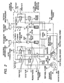
- Fig. 2 is a hydraulic circuit diagram of brake fluid of the brake control device for a motorcycle.
- a brake control device for the motorcycle 100A is to properly control a brake force (brake hydraulic pressure) applied to a front wheel FT and a rear wheel RT (hereinafter, also may be referred to as a wheel FT and a wheel RT) of a vehicle BK1.
- the control device mainly includes a hydraulic pressure unit 10 provided with oil passages (flow passages for a brake fluid) and various components, and a control device 20A properly controlling the various components in the hydraulic pressure unit 10.
- the control device 20A in the brake control device for the motorcycle 100A is connected to: (1) a first pressure sensor 51 and a second pressure sensor 52 (hereinafter, also may be referred to as a pressure sensor 51 and a pressure sensor 52) detecting brake hydraulic pressures (first master cylinder pressure and second master cylinder pressure) generated in a first master cylinder M1 and a second master cylinder M2; and (2) a front wheel speed sensor 53 and a rear wheel speed sensor 54 (hereinafter, also may be referred to as wheel speed sensors 53 and 54) detecting wheel speeds (front wheel speed V F and rear wheel speed V R ) of the front wheel FT and the rear wheel RT.
- a first pressure sensor 51 and a second pressure sensor 52 (hereinafter, also may be referred to as a pressure sensor 51 and a pressure sensor 52) detecting brake hydraulic pressures (first master cylinder pressure and second master cylinder pressure) generated in a first master cylinder M1 and a second master cylinder M2; and (2) a front wheel speed sensor 53 and a rear
- the control device 20A includes, for example, a CPU, a RAM, a ROM and an input/output circuit to perform calculation processes on the basis of inputs from the pressure sensors 51 and 52 and the wheel speed sensors 53 and 54 and data and programs stored in the ROM so that control operations are performed.
- a first front wheel cylinder FH1 is a hydraulic device converting the brake hydraulic pressure generated in the first master cylinder M1 and the brake control device for the motorcycle 100A to an operation force for a front wheel brake (a front wheel brake mechanism) FB provided in the front wheel FT.
- a second front wheel cylinder FH2 is a hydraulic device converting the brake hydraulic pressure generated by the second master cylinder M2 and the brake control device for the motorcycle 100A to the operation force for the front wheel brake FB provided in the front wheel FT.
- a rear wheel cylinder RH is a hydraulic device converting the brake hydraulic pressure generated by the second master cylinder M2 and the brake control device for the motorcycle 100A to the operation force for a rear wheel brake (a rear wheel brake mechanism) RB provided in the rear wheel RT.
- the front wheel cylinder FH1, the second front wheel cylinder FH2 and the rear wheel cylinder RH are connected to the hydraulic pressure unit 10 of the brake control device for the motorcycle 100A via respective pipe lines.
- the hydraulic pressure unit 10 of the brake control device for the motorcycle 100A is disposed between the first master cylinder M1 and the second master cylinder M2 generating the brake hydraulic pressure in response to a force applied to a first brake operation element L1 and a second brake operation element L2 by a rider.
- the hydraulic pressure unit 10 includes the front wheel brake FB and the rear wheel brake RB, and is configured to include a pump body 10a which is a base body having oil passages in which the brake fluid flows and a plurality of inlet valves 11 and outlet valves 12 disposed in the fluid passages.
- the first master cylinder M1 is connected to an output hydraulic passage A1 formed in the pump body 10a, and a wheel hydraulic passage B1 formed in the pump body 10a is connected to the first front wheel cylinder FH1.
- the second master cylinder M2 is connected to an output hydraulic passage A2 formed in the pump body 10a, and a wheel hydraulic passage B2 formed in the pump body 10a is connected to the second front wheel cylinder FH2 and the rear wheel cylinder RH.
- the oil passage connected to the first master cylinder M1 generally extends from the first master cylinder M1 to the first front wheel cylinder FH1 so that the operation force applied to the first brake operation element L1 is transmitted to the front wheel brake FB.
- oil passage connected to the second master cylinder M2 generally extends from the second master cylinder M2 to the second front wheel cylinder FH2 and the rear wheel cylinder RH, and the operation force applied to the second brake operation element L2 is transmitted to the first wheel brake FB and the rear wheel brake RB.
- An inlet valve 11, an outlet valve 12, and a check valve 11a corresponding to the front wheel brake FB are provided in the oil passage connecting the first cylinder M1 to the first front wheel cylinder FH1.
- Two inlet valves 11, two outlet valves 12, and two check valves 11a corresponding to the front wheel brake FB and the rear wheel brake RB are provided in the oil passage connecting the second master cylinder M2, the second front wheel cylinder FH2 and the rear wheel cylinder RH.
- Two reservoirs 13, two pumps 14, two suction valves 15, two discharge valves 16, two dampers 17 and two orifices 17a corresponding to the first master cylinder M1 and the second master cylinder M2 are provided in the pump body 10a.
- the hydraulic pressure unit 10 includes an electric motor 18 to drive two pumps 14.
- the inlet valves 11 are normally open electromagnetic valves. Each of the inlet valves is disposed between the first master cylinder M1 and the first front wheel cylinder FH1 (between the output hydraulic passage A1 and the wheel hydraulic passage B1), between the second master cylinder M2 and the second front wheel cylinder FH2 (between the output hydraulic passage A2 and the wheel hydraulic passage B2), and between the second master cylinder M2 and the rear wheel cylinder RH (between the output hydraulic passage A2 and the wheel hydraulic passage B2), respectively.
- the inlet valves 11 are normally opened, the brake hydraulic pressure is permitted to be trasmitted from the first master cylinder M1 to the first front wheel cylinder FH1, and from the second master cylinder M2 to the second front wheel cylinder FH2 and the rear wheel cylinder RH.
- the inlet valves 11 are closed by the control device 20 so that the brake hydraulic pressure applied from the first brake operation element L1 to the front wheel brake FB and from the second brake operation element L2 to the front wheel brake FB and the rear wheel brake RB is isolated.
- the outlet valves 12 are normally open electromagnetic valves. Each of the outlet valves 12 is disposed between the first front wheel cylinder FH1 and the reservoir 13 (in an release passage C1), between the second front wheel cylinder FH2 and the reservoir 13 (in an release passage C2), and between the rear wheel cylinder RH and the reservoir 13 (in the release passage C2). Normally, the outlet valves 12 are closed. However, when the front wheel FT and the rear wheel RT are almost locked, the outlet valves 12 are opened by the control device 20 so that the brake fluid applied to the front wheel brake FB and the rear wheel brake RB flows into the reservoirs 13 and the hydraulic pressured applied thereto is released.
- the check valves 11a connected in parallel to the inlet valve 11 permit a brake fluid to flow in a direction from the first front wheel cylinder FH1 to the first master cylinder M1, from the second front wheel cylinder FH2 to the second master cylinder M2, and from the rear wheel cylinder RH to the second master cylinder M2 only. Even when there is no input from the first brake operation element L1 and the second brake operation element L2 and the inlet valves 11 are closed, the check valves 11a permit the brake fluid to flow in a direction from the respective wheel cylinders FH1, FH2 and RH to the master cylinder M1 and M2.
- the reservoirs 13 have a function to absorb the brake fluid flowing by releasing the outlet valves 12.
- the pump 14 includes the suction valve 15 and the discharge valve 16, and has a function to suck out the brake fluid absorbed by the reservoir 13 and return the brake fluid to the master cylinders M1 and M2.
- the pump 14, the suction valve 15 and the discharge valve 16 are shown as separate parts in Fig. 2 . However, in this embodiment, the suction valve 15 and the discharge valve 16 are integrally assembled in the pump 14.
- the suction valve 15 is provided between the reservoir 13 and an upstream side of the pump 14, and is configured to permit the brake fluid to flow in a direction from the reservoir 13 to the upstream side of the pump 14.
- the discharge valve 16 is provided between a downstream side of the pump 14 and the master cylinders M1 and M2, and is configured to permit a brake fluid to flow in a direction from the downstream side of the pump 14 to the master cylinders M1 and M2. Pulsation of the brake fluid discharged to the master cylinders M1 and M2 via the discharge valve 16 is absorbed by the damper 17 and the orifice 17a.
- a delay valve 19 is provided between the second front wheel cylinder FH2 and the inlet valve 11 corresponding to the second front wheel cylinder FH2.
- the delay valve 19 has a function to transmit the pressure applied to the brake fluid by operating the second brake operation element L2 to the rear wheel cylinder RH and the second front wheel cylinder FH2, and the pressure transmitted to the second front wheel cylinder FH2 is smaller than the pressure transmitted to the rear wheel cylinder RH.
- Fig. 3 is a block diagram showing a brake operating unit for motorcycle of the first embodiment of the present invention.
- the control device 20A includes: a front wheel speed obtaining unit 21; a rear wheel speed obtaining unit 22; an estimated motorcycle speed calculation unit 23; an estimated vehicle body deceleration calculation unit 24; an ABS control unit 25; a rear wheel lift-up judgment unit 26; a front wheel braking force control unit 27; and a judging reference change unit 28.
- the front wheel speed obtaining unit 21 controls a front wheel speed sensor 53 and obtains front wheel speed V F detected by the front wheel speed sensor 53.
- the thus obtained front wheel speed V F is outputted to the estimated motorcycle speed calculation unit 23, the estimated vehicle body deceleration calculation unit 24 and the ABS control unit 25.
- the rear wheel speed obtaining unit 22 controls the rear wheel speed sensor 54 and obtains rear wheel speed V R detected by the rear wheel speed sensor 54.
- the thus obtained rear wheel speed V R is outputted to the estimated motorcycle speed calculation unit 23 and the ABS control unit 25.
- the estimated motorcycle speed calculation unit 23 calculates estimated motorcycle speed V BK by using front wheel speed V F and rear wheel speed V R .
- estimated motorcycle speed V BK can be calculated by the following formula (1) according to front wheel speed V F , which is detected by the front wheel speed sensor 53, and rear wheel speed V R , which is detected by the rear wheel speed sensor 54.
- V BK V F + V R / 2
- Estimated motorcycle speed V BK which has been calculated, is outputted to ABS control unit 25.
- the estimated vehicle body deceleration calculation unit 24 calculates estimated vehicle body deceleration d BK by using only front wheel speed V F as a deceleration element. In other words, the estimated vehicle body deceleration calculation unit 24 calculates estimated vehicle body deceleration d BK without using rear wheel speed V R . As shown in Fig. 4 , the estimated vehicle body deceleration calculation unit 24 includes: a front wheel speed storage means 24a; and an estimated vehicle body deceleration calculation portion 24b.
- the front wheel speed storage means 24a stores front wheel speed V F for each cycle longer than a predetermined control cycle. In the present embodiment, front wheel speed V F is stored.
- the thus stored front wheel speed V F is renewed by a renewal cycle (for example, a renewal cycle longer than the control cycle by 5 times) which is longer than the predetermined control cycle.
- This renewal cycle is measured by a counter provided in the front wheel speed storage portion 24a.
- the estimated vehicle body deceleration calculation portion 24b calculates estimated vehicle body deceleration d BK of this time by using front wheel speed V F , which is obtained this time, and previous front wheel speed V F which was stored before front wheel speed V F obtained this time.
- estimated vehicle body deceleration d BK of this time is calculated by using front wheel speed V F , which is obtained this time, and by using previous front wheel speed V F which was stored in a cycle right before the renewal cycle of this time.
- ABS control unit 25 judges the necessity of ABS control of controlling wheel brakes FB and RB according to front wheel speed V F , rear wheel speed V R and estimated motorcycle speed V BK .
- ABS control unit 25 performs ABS controls (decompression control) the braking forces of wheel brakes FB and RB so as to suppress an amount of slippage of each of front wheel FT and rear wheel RT.
- ABS control unit 25 calculates braking forces of front wheel FT and rear wheel RT according to detection values of the first pressure sensor 51 and the second pressure sensor 52 and also according to amounts of driving of the inlet valves 11 and the outlet valves 12. That is, ABS control unit 25 calculates the front wheel cylinder pressure and the rear wheel cylinder pressure and controls so that the front wheel cylinder pressure and the rear wheel cylinder pressure can follow target values of control.
- the rear wheel lift-up judgment unit 26 judges that there is a possibility of rear wheel lift-up when a state, in which estimated vehicle body deceleration d BK is higher than reference deceleration d TH , lasts for a period of time longer than reference time T TH .
- the lasting time of the state, in which estimated vehicle body deceleration d BK is a deceleration higher than reference deceleration d TH is measured by a counter provided in the rear wheel lift-up judgment unit 26.
- the rear wheel lift-up judgment unit 26 repeatedly conducts judgment according to a predetermined control cycle. A result of judgment is outputted to the front wheel braking force control unit 27.
- the front wheel braking force control unit 27 controls amounts of driving of the inlet valves 11 and the outlet valves 12 on the front brake FB side and also controls an amount of driving of the electric motor 18, so that a braking force of front brake FB can be reduced.
- the higher deceleration a difference ⁇ d ( ⁇ d
- the higher deceleration a difference ⁇ d ( ⁇ d
- the above change may be conducted either continuously or intermittently.
- reference deceleration d TH is changed to a low deceleration. Therefore, it is possible to early judge that the possibility of the rear wheel lift-up. Therefore, the rear wheel can be early prevented from being lifted up.
- FIG. 5 is a time chart for explaining the method of controlling the braking force of front wheel brake FB conducted by the control device 20A of the first embodiment of the present invention.
- the front wheel braking force control unit 27 may be composed in such a manner that the larger ⁇ d is, the larger the amount of deceleration of front wheel cylinder pressure P F is increased.
- the following constitution may be adopted.
- Motorcycle BK1 is provided with a road surface gradient sensor for detecting a road surface gradient
- the control device 20A is provided with a road surface gradient obtaining unit that obtains a road surface gradient
- the rear wheel lift-up judgment unit 26 reduces reference deceleration d TH when a down-gradient is large and the rear wheel lift-up judgment unit 26 increases reference deceleration d TH when an up-gradient is large.
- the following constitution of the rear wheel lift-up judgment unit 26 may be adopted. The larger ⁇ d is, the shorter reference time T TH is reduced.
- FIG. 6 is a time chart for explaining the method of calculating estimated vehicle body deceleration d BK by the control device 20A of the first embodiment of the present invention.
- the front wheel speed storage portion 24a stores and renews front wheel speed V F for each renewal cycle T 1 by using a counter provided inside. In this case at time the t 11 , t 12 , t 13 , t 14 , t 15 and t 16 , front wheel speed V F is renewed, and the front wheel speed storage portion 24a stores two front wheel speeds V F right before.
- Estimated vehicle body deceleration d BK at the time t 121 in the time t 12 to t 13 is calculated by using front wheel speed V F at the cycle time (the time at which the contour is reset) right before renewal cycle T1 by one, that is, estimated vehicle body deceleration d BK at the time t 121 in the time t 12 to t 13 is calculated by using front wheel speed V F (t 11 ) at the time t 121 .
- estimated vehicle body deceleration d BK (t 121 ) at the time t 121 is obtained from the following formula (2) according to front wheel speed V F (t 121 ) at time t 121 .
- d BK t 121 V F t 121 - V F t 11 / t 121 - t 11
- estimated vehicle body deceleration d BK is calculated according to an interval longer than renewal cycle T1 (in this case, the t 11 to t 121 ). Therefore, it is possible to suppress an influence of an instantaneous change in front wheel speed V F and to conduct controlling by using an appropriately stable estimated vehicle body deceleration d BK .
- ABS control is conducted by using estimated motorcycle speed V BK which is based on front wheel speed V F and rear wheel speed V R . Accordingly, it is possible to enhance accuracy of the judgment of judging whether or not the rear wheel is lifted while accuracy of ABS control is being maintained.
- Fig. 7 is an arrangement view showing the motorcycle provided with the brake control device for a motorcycle of the second embodiment of the present invention.
- the brake operating unit 100B for motorcycle of the second embodiment is mounted on motorcycle BK2.
- Motorcycle BK2 further includes a longitudinal direction acceleration sensor 55 for detecting a longitudinal direction acceleration of motorcycle BK2.
- Fig. 8 is a block diagram showing a brake control device for a motorcycle of the second embodiment of the present invention.
- the control unit 20B includes a longitudinal direction acceleration obtaining unit 29, which is a functional portion, instead of the estimated vehicle body deceleration means 24.
- the longitudinal direction acceleration obtaining unit 29 controls a longitudinal direction acceleration sensor 55 and obtains longitudinal direction acceleration a BK detected by the longitudinal direction acceleration sensor 55.
- the thus obtained longitudinal direction acceleration a BK is outputted to the rear wheel lift-up judgment unit 26 and the judging reference change unit 28.
- the rear wheel lift-up judgment unit 26 and the judging reference change unit 28 carry out the respective functions by using longitudinal direction acceleration a BK instead of body deceleration d BK which is used in the first embodiment.
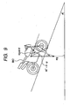
- Fig. 9 is a schematic illustration showing a state in which a motorcycle of the second embodiment runs on a downward slope.
- Fig. 10 is a graph showing a relation between the limit acceleration of generating a rear wheel lift-up on a flat road and the detection value of the longitudinal direction acceleration sensor at the time of the limit of generating a rear wheel lift-up on a downward slope.
- a BK d BK + g ⁇ sin ⁇
- reference mark g is the gravitational acceleration.
- Reference mark m shown in Fig. 9 is the mass of motorcycle BK2 (and a rider).
- longitudinal direction acceleration a BK which is detected by the longitudinal direction acceleration sensor 55, is a value at which an gradient of the road surface is compensated. That is, g ⁇ sin ⁇ is a road surface gradient compensation value.
- the longitudinal direction acceleration obtaining unit 29 obtains a sum of the actual deceleration in the direction of the gradient face of motorcycle BK2 and the component in the gradient face direction of the gravity (including the gravity acting on a rider) acting on motorcycle BK2.
- a value, which is obtained by the longitudinal direction acceleration obtaining unit 29 when motorcycle BK2 is running at the limit deceleration of generating a rear wheel lift-up is substantially equal to a value which is obtained by the longitudinal acceleration obtaining unit 29 at the time of running at the limit deceleration of generating a rear wheel lift-up of motorcycle BK2 when motorcycle BK2 is running on the flat road.
- a detection value, which is detected by the longitudinal direction acceleration sensor 55 is compensated by the gradient of the road surface. Accordingly, as shown in Fig. 10 , even when road surface gradient ⁇ is increased, the detection value, which is detected by the longitudinal direction acceleration sensor 55 at the time of the limit of generation of a rear wheel lift-up on a downward slope, that is, the value, which is obtained by the longitudinal direction acceleration obtaining unit 29, is seldom changed with respect to the limit acceleration of generation of a rear wheel lift-up at the time of running on the flat road. Accordingly, even when a plurality of reference deceleration d TH are not set corresponding to the road surface incline, it is possible to enhance accuracy of judging a rear wheel lift-up while accuracy of ABS control is being maintained. Further, a high deceleration on the flat road and a suppression of a rear wheel lift-up on the downward slope can be compatible with each other.
- Fig. 11 is a time chart showing an example of control conducted by the control unit of the second embodiment.
- a compensation of the road surface gradient is made for longitudinal direction acceleration a BK
- d BK calculated according to front wheel speed V F
Landscapes
- Engineering & Computer Science (AREA)
- Transportation (AREA)
- Mechanical Engineering (AREA)
- Regulating Braking Force (AREA)
- Hydraulic Control Valves For Brake Systems (AREA)
Description
- The present invention is related to a brake control device for a motorcycle that prevents a wheel of the motorcycle from being locked at the time of braking operation.
- There is known a brake control system using an ABS system to prevent a so-called "rear wheel lift-up (also referred to as rear wheel load releasing, jackknife, or rear lift-up)" that load applied to wheels is shifted from a rear wheel to a front wheel so that a rear wheel is lifted up at the time of braking a vehicle, particularly, at the time of strongly decelerating the vehicle.
In a conventional brake operating unit for motorcycle, a generation of the phenomenon, in which the rear wheel is lifted up, is judged when a provisional body speed is not less than a predetermined value after the provisional body speed has been calculated by selecting a higher wheel speed from the front wheel speed and the rear wheel speed. Concerning this matter, refer to Japanese Patent Unexamined PublicationJP-A-2002-29403 - In general, in the motorcycle, a rear wheel is driven. Therefore, a state of driving the rear wheel is variously changed by the operation of a rider, for example, by operating a rear brake, a clutch, a gear position and so forth. Accordingly, when a provisional body speed is calculated by referring to both the front wheel speed and the rear wheel speed in the same manner as that of the conventional brake control device for a motorcycle, a result of the judgment tends to deviate. Accordingly, there is a possibility that a sufficiently high judgment accuracy can not be obtained.
-
US 2003/0066720 A1 discloses a method for detecting lifting of a rear wheel andUS 5,324,102 discloses an apparatus for regulating the braking force of motorcycles. - The present invention has been accomplished in view of the above circumstances. It is a task of the present invention to provide a brake control device for a motorcycle capable of enhancing accuracy of judging rear wheel lift-up while accuracy of ABS control is being maintained.
- In order to solve the above problems, according to a first aspect of the invention, there is provided a brake control device for a motorcycle according to claim 1.
- According to the above constitution, it is judged whether or not at least the rear wheel is lifted up only by the front wheel speed. Therefore, it is possible to exclude an influence of the rear wheel speed which tends to be changed by the operation conducted by a rider and it is possible to enhance accuracy of judging a rear wheel lift-up. On the other hand, ABS control is conducted by using the estimated motorcycle speed which is based on the front wheel speed and the rear wheel speed. Accordingly, while accuracy of ABS control is being maintained, accuracy of judging a rear wheel lift-up can be enhanced.
- According to a second aspect of the invention, as set forth in the first aspect of the invention, it is preferable that the estimated vehicle body deceleration calculation unit comprising:
- a front wheel speed storing unit that stores the obtained front wheel speed for each cycle longer than a predetermined control cycle; and
- an estimated vehicle body deceleration calculation portion that calculates an estimated vehicle body deceleration of this time by using a front wheel speed obtained in this time and a front wheel speed obtained in previous time stored in the front wheel speed storing unit,
- wherein the rear wheel lift-up judgment unit repeatedly conducts judgment according to the predetermined control cycle.
- Due to the above constitution, since the estimated vehicle body deceleration is calculated according to the front wheel speed of the past stored for each cycle longer than the control cycle, it is possible to suppress an influence of an instantaneous change in the front wheel speed and control can be made by using an appropriately stable estimated vehicle body deceleration.
- According to a third aspect of the invention, it is preferable that the brake control device as set forth in the first or second aspect of the invention, further comprising:
- a judging reference change unit that changes the reference time to be short or changing the reference deceleration to be a low deceleration when the calculated estimated vehicle body deceleration is higher than the reference deceleration.
- The higher the estimated vehicle body deceleration is, the stronger force acts on the motorcycle to lift up the rear wheel. In this case, it is necessary to quickly conduct controlling for suppressing the rear wheel from being lifted up.
Due to the above constitution, the higher the estimated vehicle body deceleration is than the reference deceleration, the shorter the reference time is changed. Alternatively, since the reference deceleration is changed to a low deceleration, it is judged early whether or not there is a possibility of rear wheel lift-up and it is possible to quickly realize the control of suppressing a rear wheel lift-up. - According to a fourth aspect of the invention, there is provided a brake control device for a motorcycle comprising:
- a front wheel speed obtaining unit that obtains a front wheel speed;
- a rear wheel speed obtaining unit that obtains a rear wheel speed;
- an estimated motorcycle speed calculation unit that calculates an estimated motorcycle speed by using the obtained front wheel speed and rear wheel speed;
- a longitudinal direction acceleration obtaining unit that obtains a longitudinal direction acceleration of the body;
- an ABS control unit that suppresses slippage of the front wheel and the rear wheel at the time of braking operation according to the estimated motorcycle speed that has been calculated;
- a rear wheel lift-up judgment unit that judges that there are any possibilities of the rear wheel being lifted when a state, where the obtained longitudinal direction acceleration is higher than a reference acceleration, lasts for a period of time longer than a reference period of time; and
- a front wheel braking force control unit that reduces a braking force of the front wheel when it is judged that the possibility of the rear wheel being lifted.
- On a downward slope, the deceleration limit, at which the rear wheel is lifted up, is decreased as compared with the deceleration limit on a flat passage. That is, in order to prevent the rear wheel from being lifted up on the downward slope, it is necessary to reduce the reference deceleration to be lower than that in the case of the flat passage.
However, it is impossible to judge from the front wheel speed and the rear wheel speed whether the motorcycle is running on the flat passage or the motorcycle is running on the downward slope at present. Therefore, in order to suppress a rear wheel lift-up on the downward hill, it is necessary to give consideration to an influence of the downward hill and previously set the reference deceleration at a lower value. However, when the reference deceleration is set in this way, on the flat passage, a reduction in speed can be made only by a deceleration considerably lower than the deceleration limit of the generation of a rear wheel lift-up.
Due to the above constitution, the longitudinal direction acceleration obtaining unit obtains a sum of an actual deceleration in the gradient face direction of the motorcycle and a component in the gradient face direction of gravity (including gravity acting on the rider) acting on the motorcycle. A value obtained by the longitudinal direction acceleration obtaining unit at the time of running of the motorcycle on the downward slope at the deceleration limit of a rear wheel lift-up is substantially equal to a value obtained by the longitudinal direction acceleration obtaining unit at the time of running of the motorcycle on the flat passage at the deceleration limit of a rear wheel lift-up. Accordingly, even when a plurality of reference declarations are not set according to the gradient of a road surface, while accuracy of ABS control is being maintained high, accuracy of judging a rear wheel lift-up can be enhanced. Further, a high deceleration on a flat road surface and a suppression of a rear wheel lift-up on a downward slope can be compatible with each other. - According to the brake control device for a motorcycle of the present invention, while accuracy of ABS control is being maintained high, it is possible to enhance accuracy of judging a rear wheel lift-up.
-
-
Fig. 1 is an arrangement view showing a motorcycle provided with a brake control device for a motorcycle of the first embodiment of the present invention; -
Fig. 2 is a hydraulic circuit diagram of brake fluid of the brake control device for a motorcycle; -
Fig. 3 is a block diagram showing a brake operating unit for motorcycle of the first embodiment of the present invention; -
Fig. 4 is a block diagram showing an estimated vehicle body deceleration calculation unit in detail; -
Fig. 5 is a time chart for explaining a method of controlling a braking force of a front wheel by a control unit of the first embodiment of the present invention; -
Fig. 6 is a time chart for explaining a method of calculating an estimated vehicle body deceleration by a control unit of the first embodiment of the present invention; -
Fig. 7 is an arrangement view showing a motorcycle provided with a brake control device for a motorcycle of the second embodiment of the present invention; -
Fig. 8 is a block diagram showing a brake control device for a motorcycle of the second embodiment of the present invention; -
Fig. 9 is a schematic illustration showing a state in which a motorcycle of the second embodiment runs on a downward slope; -
Fig. 10 is a graph showing a relation between a limit acceleration of generating a rear wheel lift-up on a flat road and a detection value of the longitudinal direction acceleration sensor at the time of the limit of generating a rear wheel lift-up on a downward slope; and -
Fig. 11 is a time chart showing an example of control conducted by the control unit of the second embodiment. - Referring to the accompanying drawings appropriately, an embodiment of the present invention will be explained in detail below. Like reference characters are used to indicate like parts and the duplicate explanations are omitted here. In the drawings to be referred,
Fig. 1 is an arrangement view showing a motorcycle provided with a brake control device for a motorcycle of the first embodiment of the present invention.Fig. 2 is a hydraulic circuit diagram of brake fluid of the brake control device for a motorcycle. - As shown in
Fig. 1 , a brake control device for themotorcycle 100A is to properly control a brake force (brake hydraulic pressure) applied to a front wheel FT and a rear wheel RT (hereinafter, also may be referred to as a wheel FT and a wheel RT) of a vehicle BK1. The control device mainly includes ahydraulic pressure unit 10 provided with oil passages (flow passages for a brake fluid) and various components, and acontrol device 20A properly controlling the various components in thehydraulic pressure unit 10.
Thecontrol device 20A in the brake control device for themotorcycle 100A is connected to: (1) afirst pressure sensor 51 and a second pressure sensor 52 (hereinafter, also may be referred to as apressure sensor 51 and a pressure sensor 52) detecting brake hydraulic pressures (first master cylinder pressure and second master cylinder pressure) generated in a first master cylinder M1 and a second master cylinder M2; and (2) a frontwheel speed sensor 53 and a rear wheel speed sensor 54 (hereinafter, also may be referred to aswheel speed sensors 53 and 54) detecting wheel speeds (front wheel speed VF and rear wheel speed VR) of the front wheel FT and the rear wheel RT.
Thecontrol device 20A includes, for example, a CPU, a RAM, a ROM and an input/output circuit to perform calculation processes on the basis of inputs from thepressure sensors wheel speed sensors
A first front wheel cylinder FH1 is a hydraulic device converting the brake hydraulic pressure generated in the first master cylinder M1 and the brake control device for themotorcycle 100A to an operation force for a front wheel brake (a front wheel brake mechanism) FB provided in the front wheel FT. A second front wheel cylinder FH2 is a hydraulic device converting the brake hydraulic pressure generated by the second master cylinder M2 and the brake control device for themotorcycle 100A to the operation force for the front wheel brake FB provided in the front wheel FT. A rear wheel cylinder RH is a hydraulic device converting the brake hydraulic pressure generated by the second master cylinder M2 and the brake control device for themotorcycle 100A to the operation force for a rear wheel brake (a rear wheel brake mechanism) RB provided in the rear wheel RT. The front wheel cylinder FH1, the second front wheel cylinder FH2 and the rear wheel cylinder RH are connected to thehydraulic pressure unit 10 of the brake control device for themotorcycle 100A via respective pipe lines. - As shown in
Fig. 2 , thehydraulic pressure unit 10 of the brake control device for themotorcycle 100A is disposed between the first master cylinder M1 and the second master cylinder M2 generating the brake hydraulic pressure in response to a force applied to a first brake operation element L1 and a second brake operation element L2 by a rider. Thehydraulic pressure unit 10 includes the front wheel brake FB and the rear wheel brake RB, and is configured to include apump body 10a which is a base body having oil passages in which the brake fluid flows and a plurality ofinlet valves 11 andoutlet valves 12 disposed in the fluid passages.
The first master cylinder M1 is connected to an output hydraulic passage A1 formed in thepump body 10a, and a wheel hydraulic passage B1 formed in thepump body 10a is connected to the first front wheel cylinder FH1. The second master cylinder M2 is connected to an output hydraulic passage A2 formed in thepump body 10a, and a wheel hydraulic passage B2 formed in thepump body 10a is connected to the second front wheel cylinder FH2 and the rear wheel cylinder RH.
The oil passage connected to the first master cylinder M1 generally extends from the first master cylinder M1 to the first front wheel cylinder FH1 so that the operation force applied to the first brake operation element L1 is transmitted to the front wheel brake FB. Then oil passage connected to the second master cylinder M2 generally extends from the second master cylinder M2 to the second front wheel cylinder FH2 and the rear wheel cylinder RH, and the operation force applied to the second brake operation element L2 is transmitted to the first wheel brake FB and the rear wheel brake RB. - An
inlet valve 11, anoutlet valve 12, and acheck valve 11a corresponding to the front wheel brake FB are provided in the oil passage connecting the first cylinder M1 to the first front wheel cylinder FH1. Twoinlet valves 11, twooutlet valves 12, and twocheck valves 11a corresponding to the front wheel brake FB and the rear wheel brake RB are provided in the oil passage connecting the second master cylinder M2, the second front wheel cylinder FH2 and the rear wheel cylinder RH.
Tworeservoirs 13, twopumps 14, twosuction valves 15, twodischarge valves 16, twodampers 17 and twoorifices 17a corresponding to the first master cylinder M1 and the second master cylinder M2 are provided in thepump body 10a. Thehydraulic pressure unit 10 includes anelectric motor 18 to drive two pumps 14. - The
inlet valves 11 are normally open electromagnetic valves. Each of the inlet valves is disposed between the first master cylinder M1 and the first front wheel cylinder FH1 (between the output hydraulic passage A1 and the wheel hydraulic passage B1), between the second master cylinder M2 and the second front wheel cylinder FH2 (between the output hydraulic passage A2 and the wheel hydraulic passage B2), and between the second master cylinder M2 and the rear wheel cylinder RH (between the output hydraulic passage A2 and the wheel hydraulic passage B2), respectively. Since theinlet valves 11 are normally opened, the brake hydraulic pressure is permitted to be trasmitted from the first master cylinder M1 to the first front wheel cylinder FH1, and from the second master cylinder M2 to the second front wheel cylinder FH2 and the rear wheel cylinder RH. When the front wheel FT and the rear wheel RT are almost locked, theinlet valves 11 are closed by the control device 20 so that the brake hydraulic pressure applied from the first brake operation element L1 to the front wheel brake FB and from the second brake operation element L2 to the front wheel brake FB and the rear wheel brake RB is isolated. - The
outlet valves 12 are normally open electromagnetic valves. Each of theoutlet valves 12 is disposed between the first front wheel cylinder FH1 and the reservoir 13 (in an release passage C1), between the second front wheel cylinder FH2 and the reservoir 13 (in an release passage C2), and between the rear wheel cylinder RH and the reservoir 13 (in the release passage C2). Normally, theoutlet valves 12 are closed. However, when the front wheel FT and the rear wheel RT are almost locked, theoutlet valves 12 are opened by the control device 20 so that the brake fluid applied to the front wheel brake FB and the rear wheel brake RB flows into thereservoirs 13 and the hydraulic pressured applied thereto is released. - The
check valves 11a connected in parallel to theinlet valve 11 permit a brake fluid to flow in a direction from the first front wheel cylinder FH1 to the first master cylinder M1, from the second front wheel cylinder FH2 to the second master cylinder M2, and from the rear wheel cylinder RH to the second master cylinder M2 only. Even when there is no input from the first brake operation element L1 and the second brake operation element L2 and theinlet valves 11 are closed, thecheck valves 11a permit the brake fluid to flow in a direction from the respective wheel cylinders FH1, FH2 and RH to the master cylinder M1 and M2. - The
reservoirs 13 have a function to absorb the brake fluid flowing by releasing theoutlet valves 12. - The
pump 14 includes thesuction valve 15 and thedischarge valve 16, and has a function to suck out the brake fluid absorbed by thereservoir 13 and return the brake fluid to the master cylinders M1 and M2. Thepump 14, thesuction valve 15 and thedischarge valve 16 are shown as separate parts inFig. 2 . However, in this embodiment, thesuction valve 15 and thedischarge valve 16 are integrally assembled in thepump 14. - The
suction valve 15 is provided between thereservoir 13 and an upstream side of thepump 14, and is configured to permit the brake fluid to flow in a direction from thereservoir 13 to the upstream side of thepump 14. - The
discharge valve 16 is provided between a downstream side of thepump 14 and the master cylinders M1 and M2, and is configured to permit a brake fluid to flow in a direction from the downstream side of thepump 14 to the master cylinders M1 and M2. Pulsation of the brake fluid discharged to the master cylinders M1 and M2 via thedischarge valve 16 is absorbed by thedamper 17 and theorifice 17a. - A
delay valve 19 is provided between the second front wheel cylinder FH2 and theinlet valve 11 corresponding to the second front wheel cylinder FH2. According to its mechanical configuration, thedelay valve 19 has a function to transmit the pressure applied to the brake fluid by operating the second brake operation element L2 to the rear wheel cylinder RH and the second front wheel cylinder FH2, and the pressure transmitted to the second front wheel cylinder FH2 is smaller than the pressure transmitted to the rear wheel cylinder RH. By operating thedelay valve 19, a time to start an application of the brake hydraulic pressure to the second front wheel cylinder FH2 may come a little later than a time to start an application of the brake hydraulic pressure to the rear wheel cylinder RH. - Successively, the
control device 20A of the first embodiment of the present invention will be explained below.Fig. 3 is a block diagram showing a brake operating unit for motorcycle of the first embodiment of the present invention.
As shown inFig. 3 , thecontrol device 20A includes: a front wheelspeed obtaining unit 21; a rear wheelspeed obtaining unit 22; an estimated motorcyclespeed calculation unit 23; an estimated vehicle bodydeceleration calculation unit 24; anABS control unit 25; a rear wheel lift-upjudgment unit 26; a front wheel brakingforce control unit 27; and a judgingreference change unit 28. - The front wheel
speed obtaining unit 21 controls a frontwheel speed sensor 53 and obtains front wheel speed VF detected by the frontwheel speed sensor 53.
The thus obtained front wheel speed VF is outputted to the estimated motorcyclespeed calculation unit 23, the estimated vehicle bodydeceleration calculation unit 24 and theABS control unit 25. - The rear wheel
speed obtaining unit 22 controls the rearwheel speed sensor 54 and obtains rear wheel speed VR detected by the rearwheel speed sensor 54.
The thus obtained rear wheel speed VR is outputted to the estimated motorcyclespeed calculation unit 23 and theABS control unit 25. - The estimated motorcycle
speed calculation unit 23 calculates estimated motorcycle speed VBK by using front wheel speed VF and rear wheel speed VR. Concerning the method of calculating estimated motorcycle speed VBK, it is possible to use a well known calculation method. For example, estimated motorcycle speed VBK can be calculated by the following formula (1) according to front wheel speed VF, which is detected by the frontwheel speed sensor 53, and rear wheel speed VR, which is detected by the rearwheel speed sensor 54.
Estimated motorcycle speed VBK, which has been calculated, is outputted toABS control unit 25. - The estimated vehicle body
deceleration calculation unit 24 calculates estimated vehicle body deceleration dBK by using only front wheel speed VF as a deceleration element. In other words, the estimated vehicle bodydeceleration calculation unit 24 calculates estimated vehicle body deceleration dBK without using rear wheel speed VR.
As shown inFig. 4 , the estimated vehicle bodydeceleration calculation unit 24 includes: a front wheel speed storage means 24a; and an estimated vehicle bodydeceleration calculation portion 24b.
The front wheel speed storage means 24a stores front wheel speed VF for each cycle longer than a predetermined control cycle. In the present embodiment, front wheel speed VF is stored. Then, the thus stored front wheel speed VF is renewed by a renewal cycle (for example, a renewal cycle longer than the control cycle by 5 times) which is longer than the predetermined control cycle. This renewal cycle is measured by a counter provided in the front wheelspeed storage portion 24a.
The estimated vehicle bodydeceleration calculation portion 24b calculates estimated vehicle body deceleration dBK of this time by using front wheel speed VF, which is obtained this time, and previous front wheel speed VF which was stored before front wheel speed VF obtained this time. In the present embodiment, estimated vehicle body deceleration dBK of this time is calculated by using front wheel speed VF, which is obtained this time, and by using previous front wheel speed VF which was stored in a cycle right before the renewal cycle of this time. -
ABS control unit 25 judges the necessity of ABS control of controlling wheel brakes FB and RB according to front wheel speed VF, rear wheel speed VR and estimated motorcycle speed VBK. When it is judged that ABS control is necessary, by controlling theinlet valves 11, theoutlet valves 12 and an amount of driving of theelectric motor 18, the ABS control unit performs ABS controls (decompression control) the braking forces of wheel brakes FB and RB so as to suppress an amount of slippage of each of front wheel FT and rear wheel RT.ABS control unit 25 calculates braking forces of front wheel FT and rear wheel RT according to detection values of thefirst pressure sensor 51 and thesecond pressure sensor 52 and also according to amounts of driving of theinlet valves 11 and theoutlet valves 12. That is,ABS control unit 25 calculates the front wheel cylinder pressure and the rear wheel cylinder pressure and controls so that the front wheel cylinder pressure and the rear wheel cylinder pressure can follow target values of control. - The rear wheel lift-up
judgment unit 26 judges that there is a possibility of rear wheel lift-up when a state, in which estimated vehicle body deceleration dBK is higher than reference deceleration dTH, lasts for a period of time longer than reference time TTH. The lasting time of the state, in which estimated vehicle body deceleration dBK is a deceleration higher than reference deceleration dTH, is measured by a counter provided in the rear wheel lift-upjudgment unit 26. The rear wheel lift-upjudgment unit 26 repeatedly conducts judgment according to a predetermined control cycle. A result of judgment is outputted to the front wheel brakingforce control unit 27. - When it is judged that there is a possibility of rear wheel lift-up, the front wheel braking
force control unit 27 controls amounts of driving of theinlet valves 11 and theoutlet valves 12 on the front brake FB side and also controls an amount of driving of theelectric motor 18, so that a braking force of front brake FB can be reduced. - The higher deceleration a difference Δd (Δd = |dBK| - |dTH|, shown in
Fig. 5 ) between estimated vehicle body deceleration dBK and reference deceleration dTH is, the shorter the judgingreference change unit 28 changes reference time TTH. Alternatively, the higher deceleration a difference Δd (Δd = |dBK| - |dTH|, shown inFig. 5 ) between estimated vehicle body deceleration dBK and reference deceleration dTH is, the lower deceleration the reference deceleration dTH is changed. The above change may be conducted either continuously or intermittently. - As described above, the higher the estimated vehicle body deceleration is than the reference speed, the shorter the reference time TTH is changed. Alternatively, reference deceleration dTH is changed to a low deceleration. Therefore, it is possible to early judge that the possibility of the rear wheel lift-up. Therefore, the rear wheel can be early prevented from being lifted up.
- Successively, explanations will be made into a method of controlling a braking force of front wheel brake FB conducted by the
control device 20A of the first embodiment.Fig. 5 is a time chart for explaining the method of controlling the braking force of front wheel brake FB conducted by thecontrol device 20A of the first embodiment of the present invention. - As shown in
Fig. 5 , when a rider conducts an inputting operation on front brake FB and a braking force is generated in front brake FB, motorcycle BK1 is decelerated. Therefore, estimated motorcycle speed VBK is reduced.
At the time t1, estimated vehicle body deceleration dBK becomes higher than reference deceleration dTH.
Therefore, a counter provided in the rear wheel lift-upjudgment unit 26 is operated and a period of time of lasting a state, in which estimated vehicle body deceleration dBK is higher than reference deceleration dTH, is measured.
At the time t2, the lasting time becomes equal to reference time TTH, the rear wheel lift-upjudgment unit 26 judges that there is possibility of the rear wheel lift-up.
According to the result of the above judgment, the front wheel brakingforce control unit 27 reduces a braking force (front wheel cylinder pressure PF) of front brake FB. - In this connection, when the lasting time becomes equal to reference time TTH, the counter is reset. Concerning this matter, refer to the time t2, t5 and t8. When estimated vehicle body deceleration dBK becomes equal to reference deceleration dTH while the counter is being operated, the counter is also reset. Concerning this matter, refer to the time t3 and t6.
In this connection, the reason why wheel cylinder pressure PF is increased in the drawing is that a rider has operated the brake. - In this connection, the front wheel braking
force control unit 27 may be composed in such a manner that the larger Δd is, the larger the amount of deceleration of front wheel cylinder pressure PF is increased.
The following constitution may be adopted. Motorcycle BK1 is provided with a road surface gradient sensor for detecting a road surface gradient, thecontrol device 20A is provided with a road surface gradient obtaining unit that obtains a road surface gradient, and the rear wheel lift-upjudgment unit 26 reduces reference deceleration dTH when a down-gradient is large and the rear wheel lift-upjudgment unit 26 increases reference deceleration dTH when an up-gradient is large.
Further, the following constitution of the rear wheel lift-upjudgment unit 26 may be adopted. The larger Δd is, the shorter reference time TTH is reduced. - Successively, explanations will be made into a method of calculating estimated vehicle body deceleration dBK by the
control device 20A of the first embodiment.Fig. 6 is a time chart for explaining the method of calculating estimated vehicle body deceleration dBK by thecontrol device 20A of the first embodiment of the present invention.
As shown inFig. 6 , the front wheelspeed storage portion 24a stores and renews front wheel speed VF for each renewal cycle T1 by using a counter provided inside. In this case at time the t11, t12, t13, t14, t15 and t16, front wheel speed VF is renewed, and the front wheelspeed storage portion 24a stores two front wheel speeds VF right before. Estimated vehicle body deceleration dBK at the time t121 in the time t12 to t13 is calculated by using front wheel speed VF at the cycle time (the time at which the contour is reset) right before renewal cycle T1 by one, that is, estimated vehicle body deceleration dBK at the time t121 in the time t12 to t13 is calculated by using front wheel speed VF (t11) at the time t121. In this case, estimated vehicle body deceleration dBK (t121) at the time t121 is obtained from the following formula (2) according to front wheel speed VF (t121) at time t121.
- As described above, according to front wheel speed VF in the past which is renewed and stored by renewal cycle T1 longer than the control cycle, estimated vehicle body deceleration dBK is calculated according to an interval longer than renewal cycle T1 (in this case, the t11 to t121). Therefore, it is possible to suppress an influence of an instantaneous change in front wheel speed VF and to conduct controlling by using an appropriately stable estimated vehicle body deceleration dBK.
- According to the
brake operating unit 100A for motorcycle of the first embodiment, it is judged that whether there is the possibility of the rear wheel lift-up only by front wheel speed VF. Therefore, it is possible to enhance accuracy of the judgment of judging whether or not the rear wheel is lifted while an influence of rear wheel speed VR, which tends to be changed by the rider's operation, is being excluded. On the other hand, ABS control is conducted by using estimated motorcycle speed VBK which is based on front wheel speed VF and rear wheel speed VR. Accordingly, it is possible to enhance accuracy of the judgment of judging whether or not the rear wheel is lifted while accuracy of ABS control is being maintained. - Next, concerning the motorcycle provided with a brake control device for a motorcycle of the second embodiment of the present invention, different points of the second embodiment from the first embodiment will be mainly explained below.
Fig. 7 is an arrangement view showing the motorcycle provided with the brake control device for a motorcycle of the second embodiment of the present invention. - As shown in
Fig. 7 , thebrake operating unit 100B for motorcycle of the second embodiment is mounted on motorcycle BK2. Motorcycle BK2 further includes a longitudinaldirection acceleration sensor 55 for detecting a longitudinal direction acceleration of motorcycle BK2. -
Fig. 8 is a block diagram showing a brake control device for a motorcycle of the second embodiment of the present invention.
As shown inFig. 8 , thecontrol unit 20B includes a longitudinal directionacceleration obtaining unit 29, which is a functional portion, instead of the estimated vehicle body deceleration means 24. - The longitudinal direction
acceleration obtaining unit 29 controls a longitudinaldirection acceleration sensor 55 and obtains longitudinal direction acceleration aBK detected by the longitudinaldirection acceleration sensor 55.
The thus obtained longitudinal direction acceleration aBK is outputted to the rear wheel lift-upjudgment unit 26 and the judgingreference change unit 28.
In the present embodiment, the rear wheel lift-upjudgment unit 26 and the judgingreference change unit 28 carry out the respective functions by using longitudinal direction acceleration aBK instead of body deceleration dBK which is used in the first embodiment. -
Fig. 9 is a schematic illustration showing a state in which a motorcycle of the second embodiment runs on a downward slope.Fig. 10 is a graph showing a relation between the limit acceleration of generating a rear wheel lift-up on a flat road and the detection value of the longitudinal direction acceleration sensor at the time of the limit of generating a rear wheel lift-up on a downward slope. As shown inFig. 9 , when motorcycle BK2 runs on a downward slope, the down-grade of which is φ, when motorcycle BK2 runs at deceleration dBK on the downward slope, longitudinal direction acceleration aBK, which is detected by the longitudinaldirection acceleration sensor 55, is obtained by the following formula (3).
In this case, reference mark g is the gravitational acceleration. Reference mark m shown inFig. 9 is the mass of motorcycle BK2 (and a rider). - As described above, on the downward slope, longitudinal direction acceleration aBK, which is detected by the longitudinal
direction acceleration sensor 55, is a value at which an gradient of the road surface is compensated. That is, g·sinφ is a road surface gradient compensation value.
When braking operation is conducted on a downward slope, the limit deceleration of generating a rear wheel lift-up is reduced as compared with a case in which the motorcycle is running on a flat road. That is, in order to suppress a rear wheel lift-up on the downward slope, it is necessary to set reference deceleration dTH at a value lower than the reference deceleration on the flat road.
However, it is impossible to judge whether motorcycle BK2 is running on a flat road or on a downward slope at present from front wheel speed VF and rear wheel speed VR. Accordingly, in order to suppress a rear wheel lift-up on the downward slope, it is necessary to previously set reference deceleration dTH at a low value while consideration is being given to an influence of the downward slope. However, when reference deceleration dTH is set as described above, on the flat road, a running speed can be reduced only by a deceleration considerably lower than the limit deceleration of generating a rear wheel lift-up.
In the present embodiment, at the time of running on a downward slope, the longitudinal directionacceleration obtaining unit 29 obtains a sum of the actual deceleration in the direction of the gradient face of motorcycle BK2 and the component in the gradient face direction of the gravity (including the gravity acting on a rider) acting on motorcycle BK2. At the time of running on the downward slope, a value, which is obtained by the longitudinal directionacceleration obtaining unit 29 when motorcycle BK2 is running at the limit deceleration of generating a rear wheel lift-up, is substantially equal to a value which is obtained by the longitudinalacceleration obtaining unit 29 at the time of running at the limit deceleration of generating a rear wheel lift-up of motorcycle BK2 when motorcycle BK2 is running on the flat road. That is, a detection value, which is detected by the longitudinaldirection acceleration sensor 55, is compensated by the gradient of the road surface. Accordingly, as shown inFig. 10 , even when road surface gradient φ is increased, the detection value, which is detected by the longitudinaldirection acceleration sensor 55 at the time of the limit of generation of a rear wheel lift-up on a downward slope, that is, the value, which is obtained by the longitudinal directionacceleration obtaining unit 29, is seldom changed with respect to the limit acceleration of generation of a rear wheel lift-up at the time of running on the flat road. Accordingly, even when a plurality of reference deceleration dTH are not set corresponding to the road surface incline, it is possible to enhance accuracy of judging a rear wheel lift-up while accuracy of ABS control is being maintained. Further, a high deceleration on the flat road and a suppression of a rear wheel lift-up on the downward slope can be compatible with each other. -
Fig. 11 is a time chart showing an example of control conducted by the control unit of the second embodiment.Fig. 11 shows an example of control when motorcycle BK runs on a downward slope, the road surface gradient of which is tanφ = 10%.
As shown inFig. 11 , since a compensation of the road surface gradient is made for longitudinal direction acceleration aBK, when judgment is conducted by using estimated vehicle body deceleration dBK calculated according to front wheel speed VF, even when control does not intervene in the decompression control of cylinder pressure of front wheel FT, it is possible to conduct decompression control of wheel cylinder pressure PF of front wheel FT. Accordingly, it is possible to suppress the rear wheel from being lifted.
Claims (3)
- A brake control device for a motorcycle (100A) comprising:a front wheel speed obtaining unit (21) that obtains a front wheel speed;a rear wheel speed obtaining unit (22) that obtains a rear wheel speed;an estimated motorcycle speed calculation unit (23) that calculates an estimated motorcycle speed by using the obtained front wheel speed and rear wheel speed;an ABS control unit (25) that suppresses slippage of the front wheel and the rear wheel at the time of braking operation according to the calculated estimated motorcycle speed;an estimated vehicle body deceleration calculation unit (24);a rear wheel lift-up judgment unit (26) that judges that there are any possibilities of the rear wheel being lifted when a state, where the calculated estimated vehicle body deceleration is higher than a reference deceleration, lasts for a period of time longer than a reference period of time; and a front wheel braking force control unit (27) that reduces a braking force of the front wheel when it is judged that there is the possibility of the rear wheel being lifted,characterised in that
the estimated vehicle body deceleration calculation unit (24) calculates an estimated vehicle body deceleration by using only the obtained front wheel speed as a speed element;
, wherein the front wheel speed (VF) is output to the estimated motorcycle speed calculation unit (23), estimated vehicle body deceleration unit (24) and the ABS control unit (25), and the rear wheel speed (VR) is output to the estimated motorcycle speed calculation unit (23) and the ABS control unit (25). - A brake control device for a motorcycle according to claim 1, wherein the estimated vehicle body deceleration calculation unit (24) comprising:a front wheel speed storing unit (24a) that stores the obtained front wheel speed for each cycle longer than a predetermined control cycle; andan estimated vehicle body deceleration calculation portion (24b) that calculates an estimated vehicle body deceleration of this time by using a front wheel speed obtained in this time and a front wheel speed obtained in previous time stored in the front wheel speed storing unit (24a),wherein the rear wheel lift-up judgment unit (26) repeatedly conducts judgment according to the predetermined control cycle.
- A brake control device for a motorcycle according to claim 1 or 2, further comprising:a judging reference change unit (28) that changes the reference time to be short or changing the reference deceleration to be a low deceleration when the calculated estimated vehicle body deceleration is higher than the reference deceleration.
Priority Applications (1)
| Application Number | Priority Date | Filing Date | Title |
|---|---|---|---|
| EP09179036A EP2161172B1 (en) | 2006-03-31 | 2007-03-29 | Brake control device for motorcycle |
Applications Claiming Priority (1)
| Application Number | Priority Date | Filing Date | Title |
|---|---|---|---|
| JP2006100882A JP4602279B2 (en) | 2006-03-31 | 2006-03-31 | Brake control device for motorcycle |
Publications (2)
| Publication Number | Publication Date |
|---|---|
| EP1842755A1 EP1842755A1 (en) | 2007-10-10 |
| EP1842755B1 true EP1842755B1 (en) | 2010-01-13 |
Family
ID=38330008
Family Applications (2)
| Application Number | Title | Priority Date | Filing Date |
|---|---|---|---|
| EP20070006540 Active EP1842755B1 (en) | 2006-03-31 | 2007-03-29 | Brake control device for motorcycle |
| EP09179036A Active EP2161172B1 (en) | 2006-03-31 | 2007-03-29 | Brake control device for motorcycle |
Family Applications After (1)
| Application Number | Title | Priority Date | Filing Date |
|---|---|---|---|
| EP09179036A Active EP2161172B1 (en) | 2006-03-31 | 2007-03-29 | Brake control device for motorcycle |
Country Status (4)
| Country | Link |
|---|---|
| EP (2) | EP1842755B1 (en) |
| JP (1) | JP4602279B2 (en) |
| DE (1) | DE602007004252D1 (en) |
| ES (2) | ES2363947T3 (en) |
Families Citing this family (23)
| Publication number | Priority date | Publication date | Assignee | Title |
|---|---|---|---|---|
| JP5022058B2 (en) | 2007-02-23 | 2012-09-12 | ボッシュ株式会社 | Brake control method and brake control apparatus for motorcycle |
| JP2009184486A (en) * | 2008-02-06 | 2009-08-20 | Hitachi Ltd | Brake device for two-wheeled vehicle |
| JP4897732B2 (en) * | 2008-03-31 | 2012-03-14 | 日信工業株式会社 | Bar handle vehicle lift tendency judgment device |
| CN102112349A (en) | 2009-04-02 | 2011-06-29 | 博世株式会社 | Brake control device |
| FR2946602A1 (en) * | 2009-06-15 | 2010-12-17 | Bosch Gmbh Robert | METHOD FOR CONTROLLING A BRAKING SYSTEM |
| JP5402466B2 (en) * | 2009-09-25 | 2014-01-29 | 株式会社アドヴィックス | Vehicle state detection device and vehicle state stabilization control device |
| JP4918146B2 (en) * | 2009-10-19 | 2012-04-18 | 日信工業株式会社 | Brake hydraulic pressure control device for bar handle vehicle |
| IT1400383B1 (en) * | 2010-05-17 | 2013-05-31 | Piaggio & C Spa | METHOD FOR RECOGNIZING THE JUMP AND FOR TRACTION MANAGEMENT IN A MOTOR WHEEL |
| JP5634295B2 (en) * | 2011-02-22 | 2014-12-03 | 本田技研工業株式会社 | Attitude control device and attitude control method for motorcycle |
| JP5627112B2 (en) * | 2011-07-01 | 2014-11-19 | 本田技研工業株式会社 | Motorcycle |
| JP5751989B2 (en) * | 2011-08-27 | 2015-07-22 | 本田技研工業株式会社 | Motorcycle |
| JP5916879B2 (en) * | 2012-10-30 | 2016-05-11 | ボッシュ株式会社 | Motorcycle for detecting switching of reference vehicle body speed in one-channel ABS system and method thereof |
| JP5887284B2 (en) * | 2013-01-25 | 2016-03-16 | 日信工業株式会社 | Brake control device for bar handle vehicle |
| CN106415078B (en) * | 2014-01-23 | 2018-04-17 | 株式会社F.C.C. | Straddle-type vehicle |
| JP6176852B2 (en) | 2014-02-18 | 2017-08-09 | 本田技研工業株式会社 | Rear wheel lift tendency judgment device for vehicles |
| JP2016222209A (en) * | 2015-06-03 | 2016-12-28 | ローベルト ボッシュ ゲゼルシャフト ミット ベシュレンクテル ハフツング | Driving control device and driving control method |
| CN109070857B (en) * | 2016-03-31 | 2021-05-14 | 本田技研工业株式会社 | Brake control device for motorcycle |
| JP6621774B2 (en) * | 2017-03-14 | 2019-12-18 | 日信工業株式会社 | Brake hydraulic pressure control device for bar handle vehicle |
| JP6606115B2 (en) | 2017-03-14 | 2019-11-13 | 日信工業株式会社 | Brake hydraulic pressure control device for bar handle vehicle |
| US10723334B2 (en) | 2017-03-28 | 2020-07-28 | Polaris Industries Inc. | Anti-lock brake system for all-terrain vehicle |
| WO2019104119A1 (en) | 2017-11-22 | 2019-05-31 | Polaris Industries Inc. | Switchable anti-lock braking system for utility vehicle |
| CN117184015A (en) | 2018-05-02 | 2023-12-08 | 北极星工业有限公司 | Operating mode of a brake system using an ATV |
| US11618422B2 (en) | 2018-11-14 | 2023-04-04 | Polaris Industries Inc. | Operating modes using a braking system for an all terrain vehicle |
Family Cites Families (19)
| Publication number | Priority date | Publication date | Assignee | Title |
|---|---|---|---|---|
| DE2133547C2 (en) * | 1971-07-06 | 1982-01-21 | Daimler-Benz Ag, 7000 Stuttgart | Brake force control for motor vehicles |
| JP2858999B2 (en) * | 1991-07-23 | 1999-02-17 | 本田技研工業株式会社 | Brake control device |
| US5257856A (en) * | 1991-07-23 | 1993-11-02 | Honda Giken Kogyo Kabushiki Kaisha | Method of and system for controlling brakes |
| US5324102A (en) | 1991-10-18 | 1994-06-28 | Fag Kugelfischer Georg Schafer Kgaa | Method and apparatus for regulating the braking force of motorcycles |
| DE4134675A1 (en) * | 1991-10-21 | 1993-04-22 | Bayerische Motoren Werke Ag | METHOD FOR CONTROLLING BRAKE FOR MOTORCYCLES |
| DE4200440A1 (en) * | 1992-01-10 | 1993-07-15 | Bayerische Motoren Werke Ag | METHOD FOR THE BRAKING CONTROL OF MOTOR SPRINGS |
| US5386366A (en) * | 1992-01-10 | 1995-01-31 | S:Fag Kugelfischer Georg Schafer Kgaa | Method of regulating the braking force of motorcycles |
| DE4204350A1 (en) * | 1992-02-14 | 1993-08-19 | Bayerische Motoren Werke Ag | ANTI-BLOCKING CONTROL SYSTEM FOR MOTORCYCLES |
| JP3269242B2 (en) * | 1994-03-07 | 2002-03-25 | トヨタ自動車株式会社 | Braking force control device |
| JP3533420B2 (en) * | 1995-12-05 | 2004-05-31 | トヨタ自動車株式会社 | Brake control device |
| JPH101040A (en) * | 1996-06-14 | 1998-01-06 | Toyota Motor Corp | Rear wheel unloading detection device, rear wheel unloading inhibition device and rear wheel dynamic load prediction device |
| JP3486060B2 (en) * | 1996-07-17 | 2004-01-13 | 日信工業株式会社 | Anti-lock brake control device for vehicles |
| JPH10329676A (en) * | 1997-05-30 | 1998-12-15 | Toyota Motor Corp | Braking device |
| JPH11180281A (en) * | 1997-12-19 | 1999-07-06 | Nisshinbo Ind Inc | Distribution of braking force control method |
| JP4169948B2 (en) * | 2000-05-11 | 2008-10-22 | ボッシュ株式会社 | Method for detecting rear wheel lift of motorcycle and brake control method |
| JP4729830B2 (en) * | 2001-09-20 | 2011-07-20 | トヨタ自動車株式会社 | Vehicle control device |
| JP3824308B2 (en) * | 2001-12-27 | 2006-09-20 | ボッシュ株式会社 | Reference speed calculation method, anti-lock brake system, anti-lock brake control program |
| JP4244182B2 (en) * | 2003-11-17 | 2009-03-25 | 本田技研工業株式会社 | Anti-lock brake control method |
| JP4429076B2 (en) * | 2004-05-24 | 2010-03-10 | トヨタ自動車株式会社 | Braking force control device |
-
2006
- 2006-03-31 JP JP2006100882A patent/JP4602279B2/en active Active
-
2007
- 2007-03-29 ES ES09179036T patent/ES2363947T3/en active Active
- 2007-03-29 DE DE200760004252 patent/DE602007004252D1/en active Active
- 2007-03-29 EP EP20070006540 patent/EP1842755B1/en active Active
- 2007-03-29 EP EP09179036A patent/EP2161172B1/en active Active
- 2007-03-29 ES ES07006540T patent/ES2338594T3/en active Active
Also Published As
| Publication number | Publication date |
|---|---|
| JP4602279B2 (en) | 2010-12-22 |
| JP2007269290A (en) | 2007-10-18 |
| DE602007004252D1 (en) | 2010-03-04 |
| EP2161172B1 (en) | 2011-05-25 |
| EP1842755A1 (en) | 2007-10-10 |
| ES2363947T3 (en) | 2011-08-19 |
| EP2161172A1 (en) | 2010-03-10 |
| ES2338594T3 (en) | 2010-05-10 |
Similar Documents
| Publication | Publication Date | Title |
|---|---|---|
| EP1842755B1 (en) | Brake control device for motorcycle | |
| JP5014162B2 (en) | Brake control method and apparatus for motorcycle | |
| EP2759453B1 (en) | Bar-handle vehicle brake control apparatus | |
| EP1839980B1 (en) | Vehicular brake hydraulic pressure control device | |
| KR100946954B1 (en) | Brake control device and method for two-wheeled motor vehicle | |
| CN112512878B (en) | Brake hydraulic pressure control device, straddle-type vehicle, and brake hydraulic pressure control method | |
| US8290678B2 (en) | Brake control method and brake control device for two-wheeled motor vehicle | |
| JP5014161B2 (en) | Brake control method and apparatus for motorcycle | |
| US8070237B2 (en) | Brake control method and system | |
| EP1839978B1 (en) | Brake control device for motorcycle | |
| EP3378718B1 (en) | Brake fluid pressure control device for vehicles with bar handle | |
| JP5014160B2 (en) | Brake control method and apparatus for motorcycle |
Legal Events
| Date | Code | Title | Description |
|---|---|---|---|
| PUAI | Public reference made under article 153(3) epc to a published international application that has entered the european phase |
Free format text: ORIGINAL CODE: 0009012 |
|
| AK | Designated contracting states |
Kind code of ref document: A1 Designated state(s): AT BE BG CH CY CZ DE DK EE ES FI FR GB GR HU IE IS IT LI LT LU LV MC MT NL PL PT RO SE SI SK TR |
|
| AX | Request for extension of the european patent |
Extension state: AL BA HR MK YU |
|
| 17P | Request for examination filed |
Effective date: 20080331 |
|
| AKX | Designation fees paid |
Designated state(s): DE ES GB IT |
|
| 17Q | First examination report despatched |
Effective date: 20080710 |
|
| GRAP | Despatch of communication of intention to grant a patent |
Free format text: ORIGINAL CODE: EPIDOSNIGR1 |
|
| GRAS | Grant fee paid |
Free format text: ORIGINAL CODE: EPIDOSNIGR3 |
|
| GRAA | (expected) grant |
Free format text: ORIGINAL CODE: 0009210 |
|
| RIN1 | Information on inventor provided before grant (corrected) |
Inventor name: HASEGAWA, TETSUYAC/O NISSIN KOGYO CO., LTD. |
|
| AK | Designated contracting states |
Kind code of ref document: B1 Designated state(s): DE ES GB IT |
|
| REG | Reference to a national code |
Ref country code: GB Ref legal event code: FG4D |
|
| REF | Corresponds to: |
Ref document number: 602007004252 Country of ref document: DE Date of ref document: 20100304 Kind code of ref document: P |
|
| REG | Reference to a national code |
Ref country code: ES Ref legal event code: FG2A Ref document number: 2338594 Country of ref document: ES Kind code of ref document: T3 |
|
| PLBE | No opposition filed within time limit |
Free format text: ORIGINAL CODE: 0009261 |
|
| STAA | Information on the status of an ep patent application or granted ep patent |
Free format text: STATUS: NO OPPOSITION FILED WITHIN TIME LIMIT |
|
| 26N | No opposition filed |
Effective date: 20101014 |
|
| PGRI | Patent reinstated in contracting state [announced from national office to epo] |
Ref country code: IT Effective date: 20110501 |
|
| REG | Reference to a national code |
Ref country code: DE Ref legal event code: R081 Ref document number: 602007004252 Country of ref document: DE Owner name: HITACHI ASTEMO, LTD., HITACHINAKA-SHI, JP Free format text: FORMER OWNER: NISSIN KOGYO CO., LTD., UEDA, NAGANO, JP |
|
| REG | Reference to a national code |
Ref country code: GB Ref legal event code: 732E Free format text: REGISTERED BETWEEN 20211210 AND 20211215 |
|
| REG | Reference to a national code |
Ref country code: ES Ref legal event code: PC2A Owner name: HITACHI ASTEMO, LTD. Effective date: 20220422 |
|
| PGFP | Annual fee paid to national office [announced via postgrant information from national office to epo] |
Ref country code: IT Payment date: 20230213 Year of fee payment: 17 Ref country code: GB Payment date: 20230202 Year of fee payment: 17 Ref country code: DE Payment date: 20230131 Year of fee payment: 17 |
|
| PGFP | Annual fee paid to national office [announced via postgrant information from national office to epo] |
Ref country code: ES Payment date: 20230404 Year of fee payment: 17 |