EP1842716A2 - Child car seat device with wing components - Google Patents
Child car seat device with wing components Download PDFInfo
- Publication number
- EP1842716A2 EP1842716A2 EP06015776A EP06015776A EP1842716A2 EP 1842716 A2 EP1842716 A2 EP 1842716A2 EP 06015776 A EP06015776 A EP 06015776A EP 06015776 A EP06015776 A EP 06015776A EP 1842716 A2 EP1842716 A2 EP 1842716A2
- Authority
- EP
- European Patent Office
- Prior art keywords
- headrest
- backrest
- pivoting block
- seat device
- wing
- Prior art date
- Legal status (The legal status is an assumption and is not a legal conclusion. Google has not performed a legal analysis and makes no representation as to the accuracy of the status listed.)
- Granted
Links
Images


Classifications
-
- B—PERFORMING OPERATIONS; TRANSPORTING
- B60—VEHICLES IN GENERAL
- B60N—SEATS SPECIALLY ADAPTED FOR VEHICLES; VEHICLE PASSENGER ACCOMMODATION NOT OTHERWISE PROVIDED FOR
- B60N2/00—Seats specially adapted for vehicles; Arrangement or mounting of seats in vehicles
- B60N2/24—Seats specially adapted for vehicles; Arrangement or mounting of seats in vehicles for particular purposes or particular vehicles
- B60N2/26—Seats specially adapted for vehicles; Arrangement or mounting of seats in vehicles for particular purposes or particular vehicles for children
- B60N2/28—Seats readily mountable on, and dismountable from, existing seats or other parts of the vehicle
- B60N2/2851—Seats readily mountable on, and dismountable from, existing seats or other parts of the vehicle provided with head-rests
-
- B—PERFORMING OPERATIONS; TRANSPORTING
- B60—VEHICLES IN GENERAL
- B60N—SEATS SPECIALLY ADAPTED FOR VEHICLES; VEHICLE PASSENGER ACCOMMODATION NOT OTHERWISE PROVIDED FOR
- B60N2/00—Seats specially adapted for vehicles; Arrangement or mounting of seats in vehicles
- B60N2/24—Seats specially adapted for vehicles; Arrangement or mounting of seats in vehicles for particular purposes or particular vehicles
- B60N2/26—Seats specially adapted for vehicles; Arrangement or mounting of seats in vehicles for particular purposes or particular vehicles for children
- B60N2/28—Seats readily mountable on, and dismountable from, existing seats or other parts of the vehicle
- B60N2/2857—Seats readily mountable on, and dismountable from, existing seats or other parts of the vehicle characterised by the peculiar orientation of the child
- B60N2/286—Seats readily mountable on, and dismountable from, existing seats or other parts of the vehicle characterised by the peculiar orientation of the child forward facing
-
- B—PERFORMING OPERATIONS; TRANSPORTING
- B60—VEHICLES IN GENERAL
- B60N—SEATS SPECIALLY ADAPTED FOR VEHICLES; VEHICLE PASSENGER ACCOMMODATION NOT OTHERWISE PROVIDED FOR
- B60N2/00—Seats specially adapted for vehicles; Arrangement or mounting of seats in vehicles
- B60N2/24—Seats specially adapted for vehicles; Arrangement or mounting of seats in vehicles for particular purposes or particular vehicles
- B60N2/26—Seats specially adapted for vehicles; Arrangement or mounting of seats in vehicles for particular purposes or particular vehicles for children
- B60N2/28—Seats readily mountable on, and dismountable from, existing seats or other parts of the vehicle
- B60N2/2866—Seats readily mountable on, and dismountable from, existing seats or other parts of the vehicle booster cushions, e.g. to lift a child to allow proper use of the conventional safety belts
-
- B—PERFORMING OPERATIONS; TRANSPORTING
- B60—VEHICLES IN GENERAL
- B60N—SEATS SPECIALLY ADAPTED FOR VEHICLES; VEHICLE PASSENGER ACCOMMODATION NOT OTHERWISE PROVIDED FOR
- B60N2/00—Seats specially adapted for vehicles; Arrangement or mounting of seats in vehicles
- B60N2/24—Seats specially adapted for vehicles; Arrangement or mounting of seats in vehicles for particular purposes or particular vehicles
- B60N2/26—Seats specially adapted for vehicles; Arrangement or mounting of seats in vehicles for particular purposes or particular vehicles for children
- B60N2/28—Seats readily mountable on, and dismountable from, existing seats or other parts of the vehicle
- B60N2/2872—Seats readily mountable on, and dismountable from, existing seats or other parts of the vehicle provided with side rests
Definitions
- the present invention relates generally to a child car seat device, and more particularly to a child car seat device having headrest wing and/or backrest wing.
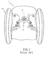
- Fig. 1 shows a conventional child car seat device 1.
- the headrest wings 14 of the child car seat device 1 is adjustable.
- the conventional headrest wings 14 are adjusted by operating knob 11 to slide along channel 12 and then to facilitate link 13.
- the present invention relates to a child car seat device with wing components to obviate one or more of the problems due to the limitations and disadvantages encountered in the prior art.
- One object of the present invention is to provide a child car seat device with wing components, whose structure is simple.
- Another object of the present invention is to provide a child car seat device with wing components, whose cost for manufacture and assembly is low.
- Yet another object of the present invention is to provide a child car seat device with wing components, which can sufficiently protect the head of the child.
- An object of the present invention is to provide a child car seat device with wing components, which can further sufficiently protect the body of the child.
- a seat device comprises a seat assembly, a backrest assembly connected with the seat assembly, and a headrest assembly connected with the backrest.
- the headrest assembly includes: a headrest body having a plurality of first engaging portions; a headrest wing component having a second engaging portion, the second engaging portion being engaged with one of the first engaging portions such that a first angle is defined between the headrest wing component and the headrest body; and a first pivot being received within the headrest wing component and the headrest body by which the headrest wing component and the headrest body are pivotally connected; wherein the first angle can be altered by selectively engaging the second engaging portion with one of the first engaging portions.
- the backrest assembly comprises: a backrest body having a plurality of third engaging portions; a backrest wing component having a fourth engaging portion, the fourth engaging portion being engaged with one of the third engaging portions such that a second angle is defined between the backrest wing component and the backrest body; and a second pivot being received within the backrest wing component and the backrest body by which the backrest wing component and the backrest body are pivotally connected; wherein the second angle can be altered by selectively engaging the fourth engaging portion with one of the third engaging portions.
- the headrest body has a first pivoting block and a first hole through the first pivoting block;
- the headrest wing component has a second pivoting block and a second hole through the second pivoting block; the first pivot is received in the first hole and the second hole.
- first engaging portions are a plurality of grooves on the first pivoting block
- second engaging portion is a rib adjacent to the second pivoting block
- the headrest body further has two first slots on the first pivoting block such that an area between the first slots are resiliently deformable, and the first engaging portions are formed on the area.
- the headrest wing component further has a first tab, which extends from an inner surface of the second pivoting block to a region above the second hole for retaining the first pivot.
- first tab inclines with an axis of the second hole, and a lower section of the first tab is separated from the inner surface of the second pivoting block.
- the headrest wing component further has a first opening formed on a top surface of the second pivoting block, and a diameter of the first opening is larger than that of the first pivot.
- the headrest assembly further includes a first fastener, the first pivot has a first recess, and the first fastener is engaged in the first recess.
- the headrest body has a first stopper, and the first angle is a maximum when the first stopper contacts with the second pivoting block.
- the headrest wing component further has a first cover for covering a gap defined between the headrest wing component and the headrest body.
- the backrest body has a third pivoting block and a third hole through the third pivoting block;
- the backrest wing component has a fourth pivoting block and a fourth hole through the fourth pivoting block; the second pivot is received in the third hole and the fourth hole.
- the third engaging portions are a plurality of grooves on the third pivoting block, and the fourth engaging portion is a rib adjacent to the fourth pivoting block.
- the backrest body further has two second slots on the third pivoting block such that an area between the second slots are resiliently deformable, and the third engaging portions are formed on the area.
- Yet another aspect of the present invention is to provide a child car seat device which comprises: a rest body having a plurality of first engaging portions at two opposite sides thereof; and a pair of wing components pivotally connected to the opposite sides of the rest body respectively, each of the wing components having a second engaging portion being engaged with one of the first engaging portions such that an angle is defined between the rest body and the each of the wing components; wherein the angle can be altered by engaging the second engaging portion selectively with the one of the first engaging portions.
- the rest body further has a first pivoting block at each of the opposite sides thereof on which the first engaging portions are formed, the each of the wing components further has a second pivoting block on which the second engaging portion is formed, the second pivoting block is coupled with the first pivoting block, and a pivot is received in both the first pivoting block and the second pivoting block.
- the first preferred embodiment of the child car seat device 2 with wing components comprises a seat assembly 3, a backrest assembly 4 pivotally connected or coupled with the seat assembly 3 at one end thereof, a headrest assembly 5 slidably coupled with the backrest assembly 4 at another end thereof.
- the headrest assembly 5 includes a plate-shaped headrest body 51, two headrest wing components 52, two first pivots 53, and two first fasteners 55.
- the headrest body 51 respectively at two sides thereof has two spaced first pivoting blocks 511, two first holes 512 longitudinally formed through each of the first pivoting blocks 511 respectively, a first stopper 513 located near the back side of the first pivoting blocks 511, two laterally first slots 515 respectively near the upper and lower edges of each first pivoting block 511, and a plurality of first engaging portions 514, such as three grooves, longitudinally formed on the circumferential surface of each first pivoting block 511.
- Each headrest wing component 52 at one side thereof has three second pivoting blocks 521, three second holes 522 longitudinally formed through each of the second pivoting blocks 521 respectively, a first cover 523 located near the back side of the second pivoting blocks 521, and two second engaging portions 524, such as ribs, respectively formed between every two adjacent second pivoting blocks 521.
- Each first pivot 53 has a first recess 531 on the distal end thereof.
- Each first fastener 55 such as a washer with claws, has a plurality of first claws 551 which inwardly extend.
- the first pivot 53 is inserted into the second holes 522 and the first holes 512.
- the first claws 551 are engaged into the first recess 531 which is revealed outside the second pivoting block 521 such that the headrest wing component 52 and the headrest body 51 are pivotally connected together.
- the headrest wing component 52 and the headrest body 51 corporately define a first angle "A" therebetween.
- the headrest wing component 52 when a force is applied to the headrest wing component 52 along the arrow "C", because the first engaging portions (such as the grooves) 514 are formed on the sidewall of the first pivoting block 511 between the two first slots 515, thus the sidewall of the first pivoting block 511 can be resiliently deformed by the second engaging portion (such as the rib) 524 to allow the second engaging portion 524 snapping into or out of the first engaging portions 514. Therefore, by selectively receiving the second engaging portion 524 within one of the first engaging portions 514 which are substantially situated with the same radius of curvature, the headrest wing component 52 can be adjusted with different first angles "A" to properly support the head of the child sitting in the child car seat device 2.
- the headrest wing component 52 when the headrest wing component 52 is pivotally rotated to the extent that the first stopper 513 abuts against the side face of the second pivoting block 521, the headrest wing component 52 cannot be further rotated outwardly. In this state shown in the Fig. 7, the first angle "A" is a maximum.
- the first cover 523 continually shields the rear gap between the headrest wing component 52 and the headrest body 51 so as to prevent the finger, which is neglectfully stretched into the gap, of the child or the user from being jammed.
- the first pivot 53 may be a rivet so as to omit the first fastener 55.
- the backrest assembly 4 includes a plate-shaped backrest body 41, two backrest wing components 42, two second pivots 43 and two second fasteners 45.
- the backrest body 41 respectively at two sides thereof has three spaced third pivoting blocks 411, three third holes 412 longitudinally formed through each of the third pivoting blocks 411 respectively, a second stopper 413 located near the back side of the third pivoting blocks 411, two laterally second slots 415 respectively near the upper and lower edges of each third pivoting block 411, and a plurality of third engaging portions 414, such as three grooves, longitudinally formed on the circumferential surface of each third pivoting block 411.
- Each backrest wing component 42 at one side thereof has four fourth pivoting block 421, four fourth holes 422 longitudinally formed through each of the fourth pivoting blocks 421 respectively, a second cover 423 located near the back side of the fourth pivoting blocks 421, and three fourth engaging portions 424, such as ribs, respectively formed between every two adjacent fourth pivoting blocks 421.
- the backrest wing component 42 when a force is applied to the backrest wing component 42 along the arrow "D", because the third engaging portions (such as the grooves) 414 are formed on the sidewall of the third pivoting block 411 between two second slots 415, thus the sidewall of the third pivoting block 411 can be resiliently deformed by the fourth engaging portion (such as the rib) 424 to allow the fourth engaging portion 424 snapping into or out of the third engaging portions 414. Therefore, by selectively receiving the fourth engaging portion 424 within one of the third engaging portions 414 which are substantially situated with the same radius of curvature, the backrest wing component 42 can be adjusted with different second angles "B" to properly support the body of the child sitting in the child car seat device 2.
- the second cover 423 continually shields the rear gap between the backrest wing component 42 and the backrest body 41 so as to prevent the finger, which is neglectfully stretched into the gap, of the child or the user from being jammed.
- the second pivot 43 may be a rivet so as to omit the second fastener 45.
- the child car seat device 2 includes both headrest wing components 52 and backrest wing components 42. However, in other preferred embodiment, the child car seat device 2 may include only headrest wing components 52 without backrest wing components 42, and vice versa.
- the second preferred embodiment additionally includes an inclined tab situated on the inner surface of one of the pivoting blocks in each wing component and an opening formed on the top surface of that pivoting block.
- the number of the pivoting blocks is reduced and there is no recess in the pivot. Therefore, only above differences will be described hereinafter while the description on the same or similar structures will be omitted. As a matter of course, the features of the first and second embodiments may be combined as well.
- the backrest wing component 42' in the second preferred embodiment includes three spaced fourth pivoting block 421', a second opening 427' formed on the top surface of the upper fourth pivoting block 421' with a diameter larger than that of the second pivot 43', and a second tab 426' which extends away from the inner surface of the upper fourth pivoting block 421' and inclines with the axis of the fourth hole 422'. Furthermore, only the upper section of the second tab 426' is connected with the inner surface of the upper fourth pivoting block 421' while the lower section of the second tab 426' is separated from the inner surface of the upper fourth pivoting block 421'. Besides, when seen downwardly from the top of backrest wing component 42', the lower end of the second tab 426' is adjacent to or in contact with the circumference of the fourth hole 422'.
- the backrest body 41' only includes two spaced third pivoting blocks 411'.
- the two third pivoting blocks 411' will be alternatively coupled with the three fourth pivoting blocks 421' and then the second pivot 43' is inserted through the second opening 427', the third holes 412' and the fourth holes 422'.
- the head of the second pivot 43' will interfere with the lower end of the second tab 426' and deform resiliently the lower section.
- the headrest wing component 52' in the second preferred embodiment includes two spaced second pivoting block 521', a first opening 527' formed on the top surface of the upper second pivoting block 521' with a diameter larger than that of the first pivot 53', and a first tab 526' which extends away from the inner surface of the upper second pivoting block 521' and inclines with the axis of the second hole 522'. Furthermore, only the upper section of the first tab 526' is connected with the inner surface of the upper second pivoting block 521' while the lower section of the first tab 526' is separated from the inner surface of the upper second pivoting block 521'. Besides, when seen downwardly from the top of headrest wing component 52', the lower end of the first tab 526' is adjacent to or in contact with the circumference of the second hole 522'.
- the headrest body 51' only includes one first pivoting block 511'.
- the first pivoting block 511' will be accommodated between two second pivoting block 521' and then the first pivot 53' is inserted through the first opening 527', the first hole 512' and the second hole 522'.
- the head of the first pivot 53' will interfere with the lower end of the first tab 526' and deform resiliently the lower section.
- the lower section of the first tab 526' will spring back and then retain the first pivot 53' in the first and second holes 512', 522'.
- first pivot 53' is retained at its upper end by the first tab 526', thus there is no need to mount the first fastener 55 similar to that in the first preferred embodiment to the first pivot 53' at its lower end. Consequently, there is no need to form the second hole 522' on the bottom surface of the lower second pivoting block 521'.
- second fastener 45 to be amounted, thus the first pivot 53', headrest wing component 52' and headrest body 51' can be easily mounted together without using the mounting tool.
- the mounting work will be easily completed because the number of the holes to be aligned with is fewer.
Landscapes
- Engineering & Computer Science (AREA)
- Health & Medical Sciences (AREA)
- Child & Adolescent Psychology (AREA)
- General Health & Medical Sciences (AREA)
- Aviation & Aerospace Engineering (AREA)
- Transportation (AREA)
- Mechanical Engineering (AREA)
- Seats For Vehicles (AREA)
- Carriages For Children, Sleds, And Other Hand-Operated Vehicles (AREA)
- Chair Legs, Seat Parts, And Backrests (AREA)
Abstract
Description
- The present invention relates generally to a child car seat device, and more particularly to a child car seat device having headrest wing and/or backrest wing.
- Fig. 1 shows a conventional child
car seat device 1. In order to meet the demands of users, theheadrest wings 14 of the childcar seat device 1 is adjustable. As shown in Fig. 1, theconventional headrest wings 14 are adjusted by operatingknob 11 to slide alongchannel 12 and then to facilitatelink 13. - However, the mechanism in above prior art, including the
knob 11 andlink 13, is complicated so that the cost for manufacturing and assembling the mechanism is high. In addition, there are no backrest wings in the conventional childcar seat device 1 such that the body of the child therein is not under protection. - Accordingly, the present invention relates to a child car seat device with wing components to obviate one or more of the problems due to the limitations and disadvantages encountered in the prior art.
- One object of the present invention is to provide a child car seat device with wing components, whose structure is simple.
- Another object of the present invention is to provide a child car seat device with wing components, whose cost for manufacture and assembly is low.
- Yet another object of the present invention is to provide a child car seat device with wing components, which can sufficiently protect the head of the child.
- An object of the present invention is to provide a child car seat device with wing components, which can further sufficiently protect the body of the child.
- Additional features and advantages of the invention will be set forth in the description which follows, and in portion will be apparent from the description, or may be learned by practice of the invention. The objectives and advantages of the invention will be realized and attained by the structure as particularly set forth in the written description and claims as well as illustrated in the appended drawings.
- The above objects are achieved by a seat device as defined in
claim 1 or claim 15, and by a child car seat device as defined in claim 19. The dependent claims define preferred and advantageous embodiments of the invention. - To achieve these and other advantages and according to the purpose of the present invention, as embodied and broadly described, a seat device comprises a seat assembly, a backrest assembly connected with the seat assembly, and a headrest assembly connected with the backrest. The headrest assembly includes: a headrest body having a plurality of first engaging portions; a headrest wing component having a second engaging portion, the second engaging portion being engaged with one of the first engaging portions such that a first angle is defined between the headrest wing component and the headrest body; and a first pivot being received within the headrest wing component and the headrest body by which the headrest wing component and the headrest body are pivotally connected; wherein the first angle can be altered by selectively engaging the second engaging portion with one of the first engaging portions.
- Another aspect of the present invention is to provide a seat device comprising a seat assembly and a backrest assembly connected with the seat assembly. The backrest assembly comprises: a backrest body having a plurality of third engaging portions; a backrest wing component having a fourth engaging portion, the fourth engaging portion being engaged with one of the third engaging portions such that a second angle is defined between the backrest wing component and the backrest body; and a second pivot being received within the backrest wing component and the backrest body by which the backrest wing component and the backrest body are pivotally connected; wherein the second angle can be altered by selectively engaging the fourth engaging portion with one of the third engaging portions.
- Moreover, the headrest body has a first pivoting block and a first hole through the first pivoting block; the headrest wing component has a second pivoting block and a second hole through the second pivoting block; the first pivot is received in the first hole and the second hole.
- Additionally, the first engaging portions are a plurality of grooves on the first pivoting block, and the second engaging portion is a rib adjacent to the second pivoting block.
- It is another preferred feature that the headrest body further has two first slots on the first pivoting block such that an area between the first slots are resiliently deformable, and the first engaging portions are formed on the area.
- It is preferred that the headrest wing component further has a first tab, which extends from an inner surface of the second pivoting block to a region above the second hole for retaining the first pivot.
- It is preferred that the first tab inclines with an axis of the second hole, and a lower section of the first tab is separated from the inner surface of the second pivoting block.
- It is preferred that the headrest wing component further has a first opening formed on a top surface of the second pivoting block, and a diameter of the first opening is larger than that of the first pivot.
- It is preferred that the headrest assembly further includes a first fastener, the first pivot has a first recess, and the first fastener is engaged in the first recess.
- It is preferred that the headrest body has a first stopper, and the first angle is a maximum when the first stopper contacts with the second pivoting block.
- It is preferred that the headrest wing component further has a first cover for covering a gap defined between the headrest wing component and the headrest body.
- It is preferred that the backrest body has a third pivoting block and a third hole through the third pivoting block; the backrest wing component has a fourth pivoting block and a fourth hole through the fourth pivoting block; the second pivot is received in the third hole and the fourth hole.
- It is preferred that the third engaging portions are a plurality of grooves on the third pivoting block, and the fourth engaging portion is a rib adjacent to the fourth pivoting block.
- It is preferred that the backrest body further has two second slots on the third pivoting block such that an area between the second slots are resiliently deformable, and the third engaging portions are formed on the area.
- Yet another aspect of the present invention is to provide a child car seat device which comprises: a rest body having a plurality of first engaging portions at two opposite sides thereof; and a pair of wing components pivotally connected to the opposite sides of the rest body respectively, each of the wing components having a second engaging portion being engaged with one of the first engaging portions such that an angle is defined between the rest body and the each of the wing components; wherein the angle can be altered by engaging the second engaging portion selectively with the one of the first engaging portions.
- It is preferred that the rest body further has a first pivoting block at each of the opposite sides thereof on which the first engaging portions are formed, the each of the wing components further has a second pivoting block on which the second engaging portion is formed, the second pivoting block is coupled with the first pivoting block, and a pivot is received in both the first pivoting block and the second pivoting block.
- It is to be understood that both the foregoing general description and the following detailed description are exemplary and explanatory and are intended to provide a further non-limiting explanation of the invention as claimed.
- The accompanying drawings, which are included to provide a further understanding of the invention and constitute a portion of the specification, illustrate embodiments of the invention and together with the description serve to explain the principle of the invention. In the drawings:
- Fig. 1 is a partially perspective view illustrating a conventional child car seat device with headrest wings;
- Fig. 2 is an assembled perspective view illustrating the child car seat device with wing components according the present application;
- Fig. 3 is an exploded perspective view illustrating the first preferred embodiment of the headrest assembly in the child car seat device with wing components according the present application;
- Fig. 4 is a sectional view taken along the line IV-IV in the Fig. 2 and illustrating the state that the headrest wing component is adjusted to the smallest angle relative to the headrest body component;
- Fig. 5 is a top view illustrating that the headrest assembly is in the state shown in the Fig. 4;
- Fig. 6 is a view similar to the Fig. 4 but illustrating the state that the headrest wing component is adjusted to the largest angle relative to the headrest body component;
- Fig. 7 is a top view illustrating that the headrest assembly is in the state shown in the Fig. 6;
- Fig. 8 is an exploded perspective view illustrating the first preferred embodiment of the backrest assembly in the child car seat device with wing components according the present application;
- Fig. 9 is a sectional view taken along the line IX-IX in the Fig. 2 and illustrating the state that the backrest wing component is adjusted to the smallest angle relative to the backrest body component;
- Fig. 10 is a top view illustrating that the backrest assembly is in the state shown in the Fig. 9;
- Fig. 11 is a view similar to the Fig. 9 but illustrating the state that the backrest wing component is adjusted to the largest angle relative to the backrest body component;
- Fig. 12 is a top view illustrating that the backrest assembly is in the state shown in the Fig. 11;
- Fig. 13 is an exploded perspective view illustrating the second preferred embodiment of the backrest assembly in the child car seat device with wing components according the present application;
- Fig. 14 is a perspective view illustrating the rear side of backrest wing component shown in the Fig. 13;
- Fig. 15 is a perspective view illustrating that the second pivot in the second preferred embodiment of the child car seat device with wing components according the present application is being mounted;
- Fig. 16 is a view similar to Fig. 15 but illustrating that the second pivot has been completely mounted;
- Fig. 17 is a view similar to Fig. 16 but being observed from the bottom;
- Fig. 18 is an exploded perspective view illustrating the second preferred embodiment of the headrest assembly in the child car seat device with wing components according the present application; and
- Fig. 19 is a perspective view illustrating the rear side of headrest wing component showing in the Fig. 18.
- As shown in Fig. 2, the first preferred embodiment of the child
car seat device 2 with wing components according to the present invention comprises aseat assembly 3, a backrest assembly 4 pivotally connected or coupled with theseat assembly 3 at one end thereof, aheadrest assembly 5 slidably coupled with the backrest assembly 4 at another end thereof. - As shown in Fig. 3, the
headrest assembly 5 includes a plate-shaped headrest body 51, twoheadrest wing components 52, twofirst pivots 53, and twofirst fasteners 55. - The
headrest body 51 respectively at two sides thereof has two spacedfirst pivoting blocks 511, twofirst holes 512 longitudinally formed through each of thefirst pivoting blocks 511 respectively, afirst stopper 513 located near the back side of thefirst pivoting blocks 511, two laterallyfirst slots 515 respectively near the upper and lower edges of eachfirst pivoting block 511, and a plurality of firstengaging portions 514, such as three grooves, longitudinally formed on the circumferential surface of eachfirst pivoting block 511. - Each
headrest wing component 52 at one side thereof has threesecond pivoting blocks 521, threesecond holes 522 longitudinally formed through each of thesecond pivoting blocks 521 respectively, afirst cover 523 located near the back side of thesecond pivoting blocks 521, and two secondengaging portions 524, such as ribs, respectively formed between every two adjacentsecond pivoting blocks 521. - Each
first pivot 53 has afirst recess 531 on the distal end thereof. Eachfirst fastener 55, such as a washer with claws, has a plurality offirst claws 551 which inwardly extend. - As shown in Figs. 3, 4 and 5, when the second pivoting blocks 521 are alternately coupled with the first pivoting blocks 511 to the extent that the
second holes 522 are aligned with thefirst holes 512 and the secondengaging portion 524 is received in one of the first engagingportions 514, thefirst pivot 53 is inserted into thesecond holes 522 and thefirst holes 512. Then, thefirst claws 551 are engaged into thefirst recess 531 which is revealed outside thesecond pivoting block 521 such that theheadrest wing component 52 and theheadrest body 51 are pivotally connected together. In addition, theheadrest wing component 52 and theheadrest body 51 corporately define a first angle "A" therebetween. - As shown in Figs. 4 and 5, when a force is applied to the
headrest wing component 52 along the arrow "C", because the first engaging portions (such as the grooves) 514 are formed on the sidewall of thefirst pivoting block 511 between the twofirst slots 515, thus the sidewall of thefirst pivoting block 511 can be resiliently deformed by the second engaging portion (such as the rib) 524 to allow the secondengaging portion 524 snapping into or out of the first engagingportions 514. Therefore, by selectively receiving the secondengaging portion 524 within one of the first engagingportions 514 which are substantially situated with the same radius of curvature, theheadrest wing component 52 can be adjusted with different first angles "A" to properly support the head of the child sitting in the childcar seat device 2. - As shown in Figs 6 and 7, when the
headrest wing component 52 is pivotally rotated to the extent that thefirst stopper 513 abuts against the side face of thesecond pivoting block 521, theheadrest wing component 52 cannot be further rotated outwardly. In this state shown in the Fig. 7, the first angle "A" is a maximum. - Furthermore, as shown in Figs 4 and 6, in the whole range of rotating the
headrest wing component 52, thefirst cover 523 continually shields the rear gap between theheadrest wing component 52 and theheadrest body 51 so as to prevent the finger, which is neglectfully stretched into the gap, of the child or the user from being jammed. - In another embodiment, the
first pivot 53 may be a rivet so as to omit thefirst fastener 55. - As shown in Fig. 8, the structures of the backrest assembly 4 are similar to those of the
headrest assembly 5. The backrest assembly 4 includes a plate-shapedbackrest body 41, twobackrest wing components 42, twosecond pivots 43 and twosecond fasteners 45. - The
backrest body 41 respectively at two sides thereof has three spaced third pivoting blocks 411, threethird holes 412 longitudinally formed through each of the third pivoting blocks 411 respectively, asecond stopper 413 located near the back side of the third pivoting blocks 411, two laterallysecond slots 415 respectively near the upper and lower edges of eachthird pivoting block 411, and a plurality of thirdengaging portions 414, such as three grooves, longitudinally formed on the circumferential surface of eachthird pivoting block 411. - Each
backrest wing component 42 at one side thereof has fourfourth pivoting block 421, fourfourth holes 422 longitudinally formed through each of the fourth pivoting blocks 421 respectively, asecond cover 423 located near the back side of the fourth pivoting blocks 421, and three fourth engagingportions 424, such as ribs, respectively formed between every two adjacent fourth pivoting blocks 421. - As shown in Figs. 8 and 9, when the fourth pivoting blocks 421 are alternately coupled with the third pivoting blocks 411 to the extent that the
fourth holes 422 are aligned with thethird holes 412 and the fourth engagingportion 424 is received in one of the thirdengaging portions 414, thesecond pivot 43 is inserted into thefourth holes 422 and thethird holes 412. Then, thesecond claws 451 are engaged into thesecond recess 431 which is revealed outside thefourth pivoting block 421 such that thebackrest wing component 42 and thebackrest body 41 are pivotally connected together. In addition, thebackrest wing component 42 and thebackrest body 41 corporately define a second angle "B" therebetween. - As shown in Figs. 9 and 10, when a force is applied to the
backrest wing component 42 along the arrow "D", because the third engaging portions (such as the grooves) 414 are formed on the sidewall of thethird pivoting block 411 between twosecond slots 415, thus the sidewall of thethird pivoting block 411 can be resiliently deformed by the fourth engaging portion (such as the rib) 424 to allow the fourth engagingportion 424 snapping into or out of the thirdengaging portions 414. Therefore, by selectively receiving the fourth engagingportion 424 within one of the thirdengaging portions 414 which are substantially situated with the same radius of curvature, thebackrest wing component 42 can be adjusted with different second angles "B" to properly support the body of the child sitting in the childcar seat device 2. - As shown in Figs 11 and 12, when the
backrest wing component 42 is pivotally rotated to the extent that thethird stopper 413 abuts against the side face of thefourth pivoting block 421, thebackrest wing component 42 cannot be further rotated outwardly. In this state shown in the Fig. 12, the second angle "B" is a maximum. - Furthermore, as shown in Figs 9 and 11, in the whole range of rotating the
backrest wing component 42, thesecond cover 423 continually shields the rear gap between thebackrest wing component 42 and thebackrest body 41 so as to prevent the finger, which is neglectfully stretched into the gap, of the child or the user from being jammed. - In another embodiment, the
second pivot 43 may be a rivet so as to omit thesecond fastener 45. - In above preferred embodiments, the child
car seat device 2 includes bothheadrest wing components 52 andbackrest wing components 42. However, in other preferred embodiment, the childcar seat device 2 may include onlyheadrest wing components 52 withoutbackrest wing components 42, and vice versa. - The main differences between the second and the first preferred embodiments of the child car seat devices reside in that the second preferred embodiment additionally includes an inclined tab situated on the inner surface of one of the pivoting blocks in each wing component and an opening formed on the top surface of that pivoting block. Besides, in the second preferred embodiment, the number of the pivoting blocks is reduced and there is no recess in the pivot. Therefore, only above differences will be described hereinafter while the description on the same or similar structures will be omitted. As a matter of course, the features of the first and second embodiments may be combined as well.
- As shown in Figs. 13 and 14, the backrest wing component 42' in the second preferred embodiment includes three spaced fourth pivoting block 421', a second opening 427' formed on the top surface of the upper fourth pivoting block 421' with a diameter larger than that of the second pivot 43', and a second tab 426' which extends away from the inner surface of the upper fourth pivoting block 421' and inclines with the axis of the fourth hole 422'. Furthermore, only the upper section of the second tab 426' is connected with the inner surface of the upper fourth pivoting block 421' while the lower section of the second tab 426' is separated from the inner surface of the upper fourth pivoting block 421'. Besides, when seen downwardly from the top of backrest wing component 42', the lower end of the second tab 426' is adjacent to or in contact with the circumference of the fourth hole 422'.
- Correspondingly, the
backrest body 41' only includes two spaced third pivoting blocks 411'. The two third pivoting blocks 411' will be alternatively coupled with the three fourth pivoting blocks 421' and then the second pivot 43' is inserted through the second opening 427', the third holes 412' and the fourth holes 422'. As shown in fig 15, in the process of mounting the second pivot 43', the head of the second pivot 43' will interfere with the lower end of the second tab 426' and deform resiliently the lower section. As shown in Fig. 16, after the head of the second pivot 43' is moved below the lower end of the second tab 426', the lower section of the second tab 426' will spring back and then retain the second pivot 43' in the third and fourth holes 412', 422' as shown in Fig. 17. - In this second preferred embodiment, since the second pivot 43' is retained at its upper end, then there is no need to mount the
second fastener 45 similar to that in the first preferred embodiment to the second pivot 43' at its lower end. Consequently, there is no need to form the fourth hole 422' on the bottom surface of the lower fourth pivoting block 421'. In addition, because there is nosecond fastener 45 to be amounted, the second pivot 43', backrest wing component 42' andbackrest body 41' can be easily mounted together without using the mounting tool. Moreover, due to the reduced number of pivoting blocks 411', 421' and the shortened second pivot 43', the mounting work will be easily completed because the number of the holes to be aligned with is fewer. - As shown in Figs 18 and 19, the headrest wing component 52' in the second preferred embodiment includes two spaced second pivoting block 521', a first opening 527' formed on the top surface of the upper second pivoting block 521' with a diameter larger than that of the first pivot 53', and a first tab 526' which extends away from the inner surface of the upper second pivoting block 521' and inclines with the axis of the second hole 522'. Furthermore, only the upper section of the first tab 526' is connected with the inner surface of the upper second pivoting block 521' while the lower section of the first tab 526' is separated from the inner surface of the upper second pivoting block 521'. Besides, when seen downwardly from the top of headrest wing component 52', the lower end of the first tab 526' is adjacent to or in contact with the circumference of the second hole 522'.
- Correspondingly, the headrest body 51' only includes one first pivoting block 511'. The first pivoting block 511' will be accommodated between two second pivoting block 521' and then the first pivot 53' is inserted through the first opening 527', the first hole 512' and the second hole 522'. In the process of mounting the first pivot 53', the head of the first pivot 53' will interfere with the lower end of the first tab 526' and deform resiliently the lower section. After the head of the first pivot 53' is moved below the lower end of the first tab 526', the lower section of the first tab 526' will spring back and then retain the first pivot 53' in the first and second holes 512', 522'.
- In this second preferred embodiment, since the first pivot 53' is retained at its upper end by the first tab 526', thus there is no need to mount the
first fastener 55 similar to that in the first preferred embodiment to the first pivot 53' at its lower end. Consequently, there is no need to form the second hole 522' on the bottom surface of the lower second pivoting block 521'. In addition, because there is nosecond fastener 45 to be amounted, thus the first pivot 53', headrest wing component 52' and headrest body 51' can be easily mounted together without using the mounting tool. Moreover, due to the reduced number of pivoting blocks 511', 521' and the shortened first pivot 53', the mounting work will be easily completed because the number of the holes to be aligned with is fewer. - This invention has been disclosed in terms of specific embodiments. It will be apparent that many modifications can be made to the disclosed structures without departing from the invention. Therefore, it is the intent of the appended claims to cover all such variations and modifications that are within the breadth and scope of this invention.
Claims (20)
- A seat device (2) comprising:a seat assembly (3);a backrest assembly (4; 4') connected with the seat assembly (3); anda headrest assembly (5; 5') connected with the backrest assembly (4; 4'); the headrest assembly (5; 5') including:a headrest body (51; 51') having a plurality of first engaging portions (514; 514');a headrest wing component (52; 52') having a second engaging portion (524; 524'), the second engaging portion being engaged with one of the first engaging portions (514; 514') such that a first angle (A) is defined between the headrest wing component (52; 52') and the headrest body (51; 51'); anda first pivot (53; 53') being received within the headrest wing (52; 52') component and the headrest body (51; 51') by which the headrest wing component and the headrest body are pivotally connected;wherein the first angle (A) can be altered by selectively engaging the second engaging portion (524; 524') with one of the first engaging portions (514; 514').
- The seat device (2) as claimed in claim 1, wherein the headrest body (51; 51') has a first pivoting block (511; 511') through which a first hole (512; 512') passes, the headrest wing component (52; 52') has a second pivoting block (521; 521') through which a second hole (522; 522') passes, and the first pivot (53; 53') is received in the first hole and the second hole.
- The seat device (2) as claimed in claim 2, wherein the first engaging portions (514; 514') are a plurality of grooves on the first pivoting block (511; 511'), and the second engaging portion (524; 524') is a rib adjacent to the second pivoting block (521; 521').
- The seat device (2) as claimed in claim 2 or claim 3, wherein the headrest body (51; 51') further has two first slots (515) on the first pivoting block (511; 511') such that an area between the first slots is resiliently deformable, and the first engaging portions (514; 514') are formed on the area.
- The seat device (2) as claimed in any one of claims 2-4, wherein the headrest wing component (52') further has a first tab (526'), which extends from an inner surface of the second pivoting block (521') to a region above the second hole (522') for retaining the first pivot (53').
- The seat device (2) as claimed in claim 5, wherein the first tab (526') inclines with an axis of the second hole (522'), and a lower section of the first tab (526') is separated from the inner surface of the second pivoting block (521').
- The seat device (2) as claimed in any one of claims 2-6, wherein the headrest wing component (52') further has a first opening (527') formed on a top surface of the second pivoting block (521'), and a diameter of the first opening is larger than that of the first pivot (53').
- The seat device (2) as claimed in any one of claims 2-7, wherein the headrest body (5; 5') has a first stopper (513), and the first angle (A) is a maximum when the first stopper contacts with the second pivoting block (521; 521').
- The seat device (2) as claimed in any one of claims 1-8, wherein the headrest assembly (5; 5') further includes a first fastener (55), the first pivot (53) has a first recess (531), and the first fastener is engaged in the first recess.
- The seat device (2) as claimed in any one of claims 1-9, wherein the headrest wing component (52; 52') further has a first cover (523) for covering a gap defined between the headrest wing component and the headrest body (51; 51').
- The seat device (2) as claimed in any one of claims 1-10, wherein the backrest assembly (4; 4') including:a backrest body (41; 41') having a plurality of third engaging portions (414; 414');a backrest wing component (42; 42') having a fourth engaging portion (424; 424'), the fourth engaging portion being engaged with one of the third engaging portions (414; 414') such that a second angle (B) is defined between the backrest wing component and the backrest body (41; 41'); anda second pivot (43; 43') being received within the backrest wing component (42; 42') and the backrest body (41; 41') by which the backrest wing component and the backrest body are pivotally connected;wherein the second angle (B) can be altered by selectively engaging the fourth engaging portion (424; 424') with one of the third engaging portions (414; 414').
- The seat device (2) as claimed in claim 11, wherein the backrest body (41; 41') has a third pivoting block (411; 411') and a third hole (412; 412') through the third pivoting block; the backrest wing component (42; 42') has a fourth pivoting block (421; 421') and a fourth hole (422; 422') through the fourth pivoting block; the second pivot (43; 43') is received in the third hole and the fourth hole.
- The seat device (2) as claimed in claim 12, wherein the third engaging portions (414; 414') are a plurality of grooves on the third pivoting block (411; 411'), and the fourth engaging portion (424; 424') is a rib adjacent to the fourth pivoting block (421; 421').
- The seat device (2) as claimed in claim 12 or claim 13, wherein the backrest body (41; 41') further has two second slots (415) on the third pivoting block (411; 411') such that an area between the second slots are resiliently deformable, and the third engaging portions (414; 414') are formed on the area.
- A seat device (2) comprising a seat assembly (3) and a backrest assembly (4; 4') connected with the seat assembly (3), the backrest assembly (4; 4') including:a backrest body (41; 41') having a plurality of engaging portions (414; 414');a backrest wing component (42; 42') having a further engaging portion (424; 424'), the further engaging portion being engaged with one of the engaging portions (414; 414') such that an angle (B) is defined between the backrest wing component (42; 42') and the backrest body (41; 41'); anda pivot (43; 43') being received within the backrest wing component (42; 42') and the backrest body (41; 41') by which the backrest wing component and the backrest body are pivotally connected;wherein the angle (B) can be altered by selectively engaging the further engaging portion (424; 424') with one of the engaging portions (414; 414').
- The seat device (2) as claimed in claim 15, wherein the backrest body (41; 41') has a pivoting block (411; 411') and a hole (412; 412') through the pivoting block; the backrest wing component (42; 42') has a further pivoting block (421; 421') and a further hole (422; 422') through the further pivoting block; the pivot (43; 43') is received in the hole and the further hole.
- The seat device (2) as claimed in claim 16, wherein the engaging portions (414; 414') are a plurality of grooves on the pivoting block (411; 411'), and the further engaging portion (424; 424') is a rib adjacent to the further pivoting block (421; 421').
- The seat device (2) as claimed in claim 16 or claim 17, wherein the backrest body (41; 41') further has two slots (415) on the pivoting block (411; 411') such that an area between the slots is resiliently deformable, and the third engaging portions (414; 414') are formed on the area.
- A child car seat device (2) comprising:a rest body (4; 5, 5') having a plurality of first engaging portions (414, 414'; 514, 514') at two opposite sides thereof; anda pair of wing components (42, 42'; 52, 52') pivotally connected to the opposite sides of the rest body (4; 5, 5') respectively, each of the wing components having a second engaging portion (424, 424'; 524, 524') being engaged with one of the first engaging portions (414, 414'; 514, 514') such that an angle (A; B) is defined between the rest body and the each of the wing components;wherein the angle (A; B) can be altered by engaging the second engaging portion (424, 424'; 524, 524') selectively with the one of the first engaging portions (414, 414' 514, 514').
- The child car seat device (2) as claimed in claim 19, wherein the rest body (4; 5, 5') further has a first pivoting block (411, 411'; 511, 511') at each of the opposite sides thereof on which the first engaging portions (414, 414'; 514, 514') are formed, and each of the wing components (42, 42'; 52, 52') further has a second pivoting block (421, 421'; 521, S21') on which the second engaging portion (424, 424'; 524, 524') is formed, the second pivoting block is coupled with the first pivoting block, and a pivot (43, 43'; 53, 53') is received in both the first pivoting block and the second pivoting block.
Applications Claiming Priority (1)
| Application Number | Priority Date | Filing Date | Title |
|---|---|---|---|
| CNU2006201125999U CN200960864Y (en) | 2006-04-04 | 2006-04-04 | Seats with wings |
Publications (3)
| Publication Number | Publication Date |
|---|---|
| EP1842716A2 true EP1842716A2 (en) | 2007-10-10 |
| EP1842716A3 EP1842716A3 (en) | 2008-11-05 |
| EP1842716B1 EP1842716B1 (en) | 2013-03-27 |
Family
ID=38241408
Family Applications (1)
| Application Number | Title | Priority Date | Filing Date |
|---|---|---|---|
| EP06015776A Active EP1842716B1 (en) | 2006-04-04 | 2006-07-28 | Child car seat device with wing components |
Country Status (3)
| Country | Link |
|---|---|
| US (1) | US7631935B2 (en) |
| EP (1) | EP1842716B1 (en) |
| CN (1) | CN200960864Y (en) |
Cited By (1)
| Publication number | Priority date | Publication date | Assignee | Title |
|---|---|---|---|---|
| GB2461137A (en) * | 2008-06-25 | 2009-12-30 | Wonderland Nursery Goods | A child seat |
Families Citing this family (38)
| Publication number | Priority date | Publication date | Assignee | Title |
|---|---|---|---|---|
| KR20090031413A (en) * | 2006-07-11 | 2009-03-25 | 인티어 오토모티브, 인크. | Adjustable bolster assembly |
| US20080067850A1 (en) * | 2006-09-19 | 2008-03-20 | Permobil Ab | Backrest for a chair |
| PL2144535T3 (en) * | 2007-01-17 | 2012-11-30 | Diono Llc | Adjustable child restraint device |
| FR2945486B1 (en) * | 2009-05-12 | 2011-05-27 | Dorel France Sa | CAR SEAT FOR CHILDREN. |
| DE102010044246B4 (en) * | 2010-09-02 | 2015-06-25 | Johnson Controls Gmbh | Headrest with two wing elements and method for mounting a wing element |
| US8465097B2 (en) * | 2010-10-05 | 2013-06-18 | Antonio Vicente | Medical support system |
| US8157287B1 (en) * | 2010-10-21 | 2012-04-17 | Cleveland Valerie N | Convertible wheelchair |
| US20120299337A1 (en) * | 2011-05-27 | 2012-11-29 | Yvonne Miller | Easy access child car seat |
| US8708415B2 (en) | 2012-05-11 | 2014-04-29 | John Gabriel | Child head restraint system and methods using same |
| US8931836B2 (en) * | 2011-09-08 | 2015-01-13 | Wonderland Nurserygoods Company Limited | Child safety seat |
| US8950813B2 (en) * | 2012-01-12 | 2015-02-10 | Ali Nawaz | Integrated adjustable headrest |
| US20150182028A1 (en) * | 2013-12-27 | 2015-07-02 | Selima Thein | Portable support apparatus for infants and toddlers |
| US8985622B1 (en) * | 2014-01-10 | 2015-03-24 | Winnie Cannon | Personal protection assembly |
| US9446694B2 (en) * | 2014-05-16 | 2016-09-20 | AISIN Technical Center of America, Inc. | Extendable comfort headrest |
| US10252657B2 (en) | 2014-12-12 | 2019-04-09 | Bombardier Inc. | Headrest with adjustable side elements |
| US10421381B2 (en) * | 2015-03-31 | 2019-09-24 | Safran Seats Usa Llc | Adjustable headrest enabling sideward leaning and seclusion |
| US10315773B1 (en) | 2015-12-14 | 2019-06-11 | Haeco Americas, Inc. | Seat system having an adjustable wraparound headrest |
| US9776590B1 (en) | 2016-06-07 | 2017-10-03 | Nathan Foser | Personal protection assembly |
| US10124699B2 (en) * | 2016-12-21 | 2018-11-13 | Lear Corporation | Seat assembly having shell with flexible bolsters |
| CN106740319A (en) * | 2017-01-18 | 2017-05-31 | 苏州瑞美科材料科技有限公司 | A kind of automobile seat side supporting pad |
| US10266088B2 (en) * | 2017-01-31 | 2019-04-23 | Ford Global Technologies, Llc | Vehicle seating assembly having abrasion resistant bolster insert |
| US10988056B2 (en) | 2017-03-23 | 2021-04-27 | Dorel Juvenile Group, Inc. | Child restraint headrest with side-wing mover |
| CN109747504B (en) * | 2017-08-24 | 2021-02-09 | 惠州市唐群座椅科技股份有限公司 | Side wing adjusting device of seat |
| JP6814110B2 (en) * | 2017-08-25 | 2021-01-13 | 日本発條株式会社 | Headrest |
| CN108032775A (en) * | 2017-11-08 | 2018-05-15 | 包头轻工职业技术学院 | The car seat headrest of security enhancing |
| CN109895664B (en) * | 2017-12-07 | 2021-11-09 | 宝钜儿童用品香港股份有限公司 | Side impact protection device and child safety seat with same |
| CN108437859A (en) * | 2018-03-13 | 2018-08-24 | 麦克英孚(宁波)婴童用品有限公司 | A kind of safety seat |
| DE202018101575U1 (en) * | 2018-03-21 | 2019-06-24 | Cybex Gmbh | Child seat for attachment to a motor vehicle seat |
| CN110962709B (en) | 2018-10-01 | 2022-10-11 | 明门瑞士股份有限公司 | Automobile safety seat and side impact protection mechanism thereof |
| JP7200701B2 (en) * | 2019-01-30 | 2023-01-10 | トヨタ紡織株式会社 | sheet |
| US11484287B2 (en) * | 2019-02-14 | 2022-11-01 | Novasignal Corp. | Systems and methods for modular headset system |
| CN110077295A (en) * | 2019-04-08 | 2019-08-02 | 好孩子儿童用品有限公司 | A kind of angle adjusting mechanism and the articles for children with the angle adjusting mechanism |
| CN111845486A (en) * | 2020-08-24 | 2020-10-30 | 安徽永驰婴童智能科技有限公司 | Headrest assemblies and child safety seats |
| EP3967550A1 (en) * | 2020-09-10 | 2022-03-16 | Windsor Machine and Stamping (2009) Ltd. | Headrest assembly with friction hinge |
| US12351090B2 (en) * | 2020-09-10 | 2025-07-08 | Windsor Machine and Stamping (2009) Ltd. | Headrest assembly with friction hinge |
| WO2022119562A1 (en) * | 2020-12-02 | 2022-06-09 | Safran Seats Usa Llc | Passenger seat headrest divider assembly |
| CN116001658A (en) * | 2022-12-17 | 2023-04-25 | 安徽鸿贝智能科技有限公司 | Backrest adjusting mechanism and child safety seat |
| US20250145295A1 (en) * | 2023-11-02 | 2025-05-08 | B/E Aerospace, Inc. | Infant/toddler restraint system for lavatory |
Family Cites Families (8)
| Publication number | Priority date | Publication date | Assignee | Title |
|---|---|---|---|---|
| JPS5631833A (en) * | 1979-08-22 | 1981-03-31 | Aisin Seiki Co Ltd | Side support device for seat |
| DE29712497U1 (en) * | 1997-07-15 | 1997-09-11 | Kiddy GmbH Autokindersitze, 07356 Thimmendorf | Child seat to be placed on a vehicle seat |
| US6092872A (en) * | 1999-10-29 | 2000-07-25 | Global Total Office | Chair wing structure |
| US6467846B2 (en) * | 2000-09-20 | 2002-10-22 | Robert Clough | Seat headrest |
| US6601804B2 (en) * | 2001-06-12 | 2003-08-05 | Jeffrey R. Bisch | Portable headrest |
| DE10215058C1 (en) * | 2002-04-05 | 2003-07-24 | Recaro Aircraft Seating Gmbh | Headrest for aircraft passenger seat provided with inclination angle and height adjustment mechanisms |
| US20040007910A1 (en) * | 2002-07-12 | 2004-01-15 | Skelly Trevor B. | Headrest mounting plate, seat headrest, and passenger seat with headrest |
| DE202005011742U1 (en) * | 2005-07-27 | 2005-11-03 | Curt Würstl Vermögensverwaltungs-Gmbh & Co. Kg | Child safety seat for use in motor vehicle, has side panels tilted into protection position from where child looks through window and restored to usage position by application of forces on panels |
-
2006
- 2006-04-04 CN CNU2006201125999U patent/CN200960864Y/en not_active Expired - Lifetime
- 2006-07-28 EP EP06015776A patent/EP1842716B1/en active Active
- 2006-07-31 US US11/495,728 patent/US7631935B2/en active Active
Non-Patent Citations (1)
| Title |
|---|
| None |
Cited By (4)
| Publication number | Priority date | Publication date | Assignee | Title |
|---|---|---|---|---|
| GB2461137A (en) * | 2008-06-25 | 2009-12-30 | Wonderland Nursery Goods | A child seat |
| US7891738B2 (en) | 2008-06-25 | 2011-02-22 | Wonderland Nurserygoods Company Limited | Child seat |
| DE102009010946B4 (en) * | 2008-06-25 | 2012-06-14 | Wonderland Nurserygoods Co., Ltd. | Child seat |
| GB2461137B (en) * | 2008-06-25 | 2012-09-05 | Wonderland Nursery Goods | Child seat |
Also Published As
| Publication number | Publication date |
|---|---|
| US20070228792A1 (en) | 2007-10-04 |
| EP1842716A3 (en) | 2008-11-05 |
| US7631935B2 (en) | 2009-12-15 |
| EP1842716B1 (en) | 2013-03-27 |
| CN200960864Y (en) | 2007-10-17 |
Similar Documents
| Publication | Publication Date | Title |
|---|---|---|
| EP1842716B1 (en) | Child car seat device with wing components | |
| US7891926B2 (en) | Fastener | |
| US7234209B2 (en) | Mounting structure and mounting method for vehicle interior parts | |
| EP3566908B1 (en) | Interior cover mount assembly | |
| US7575267B2 (en) | Metal clip for vehicle accessory fixation and structure using the same | |
| US7748782B2 (en) | Tilt adjustment mechanism for child safety seat | |
| EP1624139B1 (en) | Door handle device | |
| US20080121768A1 (en) | Bracket and head rail assembly | |
| US20070069567A1 (en) | Child car seat with adjustable armrest | |
| KR101701243B1 (en) | Helmet | |
| EP4201736A1 (en) | Safety seat | |
| JPH11287221A (en) | Clip | |
| JP4451549B2 (en) | Seating table | |
| JP2006112546A (en) | Clip | |
| JP6623742B2 (en) | Clip and pillar garnish mounting structure | |
| EP2899078A1 (en) | Multifunctional windshield wiper connection structure | |
| KR102931958B1 (en) | Suv vehicle 3-row luggage side trim with multimedia device applied | |
| JP4745702B2 (en) | Clip mounting device | |
| JP2001080469A (en) | Wiper structure | |
| JP4638389B2 (en) | clip | |
| KR100736551B1 (en) | Adapter of wiper arm | |
| JP2010125955A (en) | Slide rail apparatus for vehicle | |
| KR100685259B1 (en) | Adapter fastening structure of wiper arm | |
| KR100685257B1 (en) | Pin fastening structure of wiper arm | |
| US20090052202A1 (en) | Vehicle lamp fixing device |
Legal Events
| Date | Code | Title | Description |
|---|---|---|---|
| PUAI | Public reference made under article 153(3) epc to a published international application that has entered the european phase |
Free format text: ORIGINAL CODE: 0009012 |
|
| AK | Designated contracting states |
Kind code of ref document: A2 Designated state(s): AT BE BG CH CY CZ DE DK EE ES FI FR GB GR HU IE IS IT LI LT LU LV MC NL PL PT RO SE SI SK TR |
|
| AX | Request for extension of the european patent |
Extension state: AL BA HR MK YU |
|
| PUAL | Search report despatched |
Free format text: ORIGINAL CODE: 0009013 |
|
| AK | Designated contracting states |
Kind code of ref document: A3 Designated state(s): AT BE BG CH CY CZ DE DK EE ES FI FR GB GR HU IE IS IT LI LT LU LV MC NL PL PT RO SE SI SK TR |
|
| AX | Request for extension of the european patent |
Extension state: AL BA HR MK RS |
|
| 17P | Request for examination filed |
Effective date: 20090424 |
|
| AKX | Designation fees paid |
Designated state(s): AT BE BG CH CY CZ DE DK EE ES FI FR GB GR HU IE IS IT LI LT LU LV MC NL PL PT RO SE SI SK TR |
|
| 17Q | First examination report despatched |
Effective date: 20100315 |
|
| GRAP | Despatch of communication of intention to grant a patent |
Free format text: ORIGINAL CODE: EPIDOSNIGR1 |
|
| GRAS | Grant fee paid |
Free format text: ORIGINAL CODE: EPIDOSNIGR3 |
|
| GRAA | (expected) grant |
Free format text: ORIGINAL CODE: 0009210 |
|
| AK | Designated contracting states |
Kind code of ref document: B1 Designated state(s): AT BE BG CH CY CZ DE DK EE ES FI FR GB GR HU IE IS IT LI LT LU LV MC NL PL PT RO SE SI SK TR |
|
| REG | Reference to a national code |
Ref country code: GB Ref legal event code: FG4D |
|
| REG | Reference to a national code |
Ref country code: CH Ref legal event code: EP |
|
| REG | Reference to a national code |
Ref country code: AT Ref legal event code: REF Ref document number: 603160 Country of ref document: AT Kind code of ref document: T Effective date: 20130415 |
|
| REG | Reference to a national code |
Ref country code: IE Ref legal event code: FG4D |
|
| REG | Reference to a national code |
Ref country code: DE Ref legal event code: R096 Ref document number: 602006035257 Country of ref document: DE Effective date: 20130529 |
|
| REG | Reference to a national code |
Ref country code: NL Ref legal event code: T3 |
|
| PG25 | Lapsed in a contracting state [announced via postgrant information from national office to epo] |
Ref country code: BG Free format text: LAPSE BECAUSE OF FAILURE TO SUBMIT A TRANSLATION OF THE DESCRIPTION OR TO PAY THE FEE WITHIN THE PRESCRIBED TIME-LIMIT Effective date: 20130627 Ref country code: SE Free format text: LAPSE BECAUSE OF FAILURE TO SUBMIT A TRANSLATION OF THE DESCRIPTION OR TO PAY THE FEE WITHIN THE PRESCRIBED TIME-LIMIT Effective date: 20130327 Ref country code: LT Free format text: LAPSE BECAUSE OF FAILURE TO SUBMIT A TRANSLATION OF THE DESCRIPTION OR TO PAY THE FEE WITHIN THE PRESCRIBED TIME-LIMIT Effective date: 20130327 |
|
| REG | Reference to a national code |
Ref country code: AT Ref legal event code: MK05 Ref document number: 603160 Country of ref document: AT Kind code of ref document: T Effective date: 20130327 |
|
| REG | Reference to a national code |
Ref country code: LT Ref legal event code: MG4D |
|
| PG25 | Lapsed in a contracting state [announced via postgrant information from national office to epo] |
Ref country code: SI Free format text: LAPSE BECAUSE OF FAILURE TO SUBMIT A TRANSLATION OF THE DESCRIPTION OR TO PAY THE FEE WITHIN THE PRESCRIBED TIME-LIMIT Effective date: 20130327 Ref country code: GR Free format text: LAPSE BECAUSE OF FAILURE TO SUBMIT A TRANSLATION OF THE DESCRIPTION OR TO PAY THE FEE WITHIN THE PRESCRIBED TIME-LIMIT Effective date: 20130628 Ref country code: FI Free format text: LAPSE BECAUSE OF FAILURE TO SUBMIT A TRANSLATION OF THE DESCRIPTION OR TO PAY THE FEE WITHIN THE PRESCRIBED TIME-LIMIT Effective date: 20130327 Ref country code: LV Free format text: LAPSE BECAUSE OF FAILURE TO SUBMIT A TRANSLATION OF THE DESCRIPTION OR TO PAY THE FEE WITHIN THE PRESCRIBED TIME-LIMIT Effective date: 20130327 |
|
| PG25 | Lapsed in a contracting state [announced via postgrant information from national office to epo] |
Ref country code: BE Free format text: LAPSE BECAUSE OF FAILURE TO SUBMIT A TRANSLATION OF THE DESCRIPTION OR TO PAY THE FEE WITHIN THE PRESCRIBED TIME-LIMIT Effective date: 20130327 |
|
| PG25 | Lapsed in a contracting state [announced via postgrant information from national office to epo] |
Ref country code: CZ Free format text: LAPSE BECAUSE OF FAILURE TO SUBMIT A TRANSLATION OF THE DESCRIPTION OR TO PAY THE FEE WITHIN THE PRESCRIBED TIME-LIMIT Effective date: 20130327 Ref country code: PT Free format text: LAPSE BECAUSE OF FAILURE TO SUBMIT A TRANSLATION OF THE DESCRIPTION OR TO PAY THE FEE WITHIN THE PRESCRIBED TIME-LIMIT Effective date: 20130729 Ref country code: IS Free format text: LAPSE BECAUSE OF FAILURE TO SUBMIT A TRANSLATION OF THE DESCRIPTION OR TO PAY THE FEE WITHIN THE PRESCRIBED TIME-LIMIT Effective date: 20130727 Ref country code: EE Free format text: LAPSE BECAUSE OF FAILURE TO SUBMIT A TRANSLATION OF THE DESCRIPTION OR TO PAY THE FEE WITHIN THE PRESCRIBED TIME-LIMIT Effective date: 20130327 Ref country code: ES Free format text: LAPSE BECAUSE OF FAILURE TO SUBMIT A TRANSLATION OF THE DESCRIPTION OR TO PAY THE FEE WITHIN THE PRESCRIBED TIME-LIMIT Effective date: 20130708 Ref country code: RO Free format text: LAPSE BECAUSE OF FAILURE TO SUBMIT A TRANSLATION OF THE DESCRIPTION OR TO PAY THE FEE WITHIN THE PRESCRIBED TIME-LIMIT Effective date: 20130327 Ref country code: SK Free format text: LAPSE BECAUSE OF FAILURE TO SUBMIT A TRANSLATION OF THE DESCRIPTION OR TO PAY THE FEE WITHIN THE PRESCRIBED TIME-LIMIT Effective date: 20130327 Ref country code: AT Free format text: LAPSE BECAUSE OF FAILURE TO SUBMIT A TRANSLATION OF THE DESCRIPTION OR TO PAY THE FEE WITHIN THE PRESCRIBED TIME-LIMIT Effective date: 20130327 |
|
| PG25 | Lapsed in a contracting state [announced via postgrant information from national office to epo] |
Ref country code: PL Free format text: LAPSE BECAUSE OF FAILURE TO SUBMIT A TRANSLATION OF THE DESCRIPTION OR TO PAY THE FEE WITHIN THE PRESCRIBED TIME-LIMIT Effective date: 20130327 Ref country code: CY Free format text: LAPSE BECAUSE OF FAILURE TO SUBMIT A TRANSLATION OF THE DESCRIPTION OR TO PAY THE FEE WITHIN THE PRESCRIBED TIME-LIMIT Effective date: 20130327 |
|
| PG25 | Lapsed in a contracting state [announced via postgrant information from national office to epo] |
Ref country code: DK Free format text: LAPSE BECAUSE OF FAILURE TO SUBMIT A TRANSLATION OF THE DESCRIPTION OR TO PAY THE FEE WITHIN THE PRESCRIBED TIME-LIMIT Effective date: 20130327 |
|
| PLBE | No opposition filed within time limit |
Free format text: ORIGINAL CODE: 0009261 |
|
| STAA | Information on the status of an ep patent application or granted ep patent |
Free format text: STATUS: NO OPPOSITION FILED WITHIN TIME LIMIT |
|
| PG25 | Lapsed in a contracting state [announced via postgrant information from national office to epo] |
Ref country code: MC Free format text: LAPSE BECAUSE OF FAILURE TO SUBMIT A TRANSLATION OF THE DESCRIPTION OR TO PAY THE FEE WITHIN THE PRESCRIBED TIME-LIMIT Effective date: 20130327 Ref country code: IT Free format text: LAPSE BECAUSE OF FAILURE TO SUBMIT A TRANSLATION OF THE DESCRIPTION OR TO PAY THE FEE WITHIN THE PRESCRIBED TIME-LIMIT Effective date: 20130327 |
|
| REG | Reference to a national code |
Ref country code: CH Ref legal event code: PL |
|
| 26N | No opposition filed |
Effective date: 20140103 |
|
| REG | Reference to a national code |
Ref country code: DE Ref legal event code: R097 Ref document number: 602006035257 Country of ref document: DE Effective date: 20140103 |
|
| REG | Reference to a national code |
Ref country code: IE Ref legal event code: MM4A |
|
| PG25 | Lapsed in a contracting state [announced via postgrant information from national office to epo] |
Ref country code: LI Free format text: LAPSE BECAUSE OF NON-PAYMENT OF DUE FEES Effective date: 20130731 Ref country code: CH Free format text: LAPSE BECAUSE OF NON-PAYMENT OF DUE FEES Effective date: 20130731 |
|
| PG25 | Lapsed in a contracting state [announced via postgrant information from national office to epo] |
Ref country code: IE Free format text: LAPSE BECAUSE OF NON-PAYMENT OF DUE FEES Effective date: 20130728 |
|
| PG25 | Lapsed in a contracting state [announced via postgrant information from national office to epo] |
Ref country code: TR Free format text: LAPSE BECAUSE OF FAILURE TO SUBMIT A TRANSLATION OF THE DESCRIPTION OR TO PAY THE FEE WITHIN THE PRESCRIBED TIME-LIMIT Effective date: 20130327 |
|
| REG | Reference to a national code |
Ref country code: FR Ref legal event code: PLFP Year of fee payment: 10 |
|
| PG25 | Lapsed in a contracting state [announced via postgrant information from national office to epo] |
Ref country code: LU Free format text: LAPSE BECAUSE OF NON-PAYMENT OF DUE FEES Effective date: 20130728 Ref country code: HU Free format text: LAPSE BECAUSE OF FAILURE TO SUBMIT A TRANSLATION OF THE DESCRIPTION OR TO PAY THE FEE WITHIN THE PRESCRIBED TIME-LIMIT; INVALID AB INITIO Effective date: 20060728 |
|
| REG | Reference to a national code |
Ref country code: FR Ref legal event code: PLFP Year of fee payment: 11 |
|
| REG | Reference to a national code |
Ref country code: FR Ref legal event code: PLFP Year of fee payment: 12 |
|
| REG | Reference to a national code |
Ref country code: FR Ref legal event code: PLFP Year of fee payment: 13 |
|
| P01 | Opt-out of the competence of the unified patent court (upc) registered |
Effective date: 20230522 |
|
| PGFP | Annual fee paid to national office [announced via postgrant information from national office to epo] |
Ref country code: GB Payment date: 20250605 Year of fee payment: 20 |
|
| PGFP | Annual fee paid to national office [announced via postgrant information from national office to epo] |
Ref country code: FR Payment date: 20250627 Year of fee payment: 20 |
|
| PGFP | Annual fee paid to national office [announced via postgrant information from national office to epo] |
Ref country code: NL Payment date: 20250724 Year of fee payment: 20 |
|
| PGFP | Annual fee paid to national office [announced via postgrant information from national office to epo] |
Ref country code: DE Payment date: 20250604 Year of fee payment: 20 |