EP2899078A1 - Multifunctional windshield wiper connection structure - Google Patents
Multifunctional windshield wiper connection structure Download PDFInfo
- Publication number
- EP2899078A1 EP2899078A1 EP14152365.4A EP14152365A EP2899078A1 EP 2899078 A1 EP2899078 A1 EP 2899078A1 EP 14152365 A EP14152365 A EP 14152365A EP 2899078 A1 EP2899078 A1 EP 2899078A1
- Authority
- EP
- European Patent Office
- Prior art keywords
- windshield wiper
- main seat
- buckling
- connection structure
- cover
- Prior art date
- Legal status (The legal status is an assumption and is not a legal conclusion. Google has not performed a legal analysis and makes no representation as to the accuracy of the status listed.)
- Granted
Links
Images


Classifications
-
- B—PERFORMING OPERATIONS; TRANSPORTING
- B60—VEHICLES IN GENERAL
- B60S—SERVICING, CLEANING, REPAIRING, SUPPORTING, LIFTING, OR MANOEUVRING OF VEHICLES, NOT OTHERWISE PROVIDED FOR
- B60S1/00—Cleaning of vehicles
- B60S1/02—Cleaning windscreens, windows or optical devices
- B60S1/04—Wipers or the like, e.g. scrapers
- B60S1/32—Wipers or the like, e.g. scrapers characterised by constructional features of wiper blade arms or blades
- B60S1/40—Connections between blades and arms
- B60S1/4003—Multi-purpose connections for two or more kinds of arm ends
-
- B—PERFORMING OPERATIONS; TRANSPORTING
- B60—VEHICLES IN GENERAL
- B60S—SERVICING, CLEANING, REPAIRING, SUPPORTING, LIFTING, OR MANOEUVRING OF VEHICLES, NOT OTHERWISE PROVIDED FOR
- B60S1/00—Cleaning of vehicles
- B60S1/02—Cleaning windscreens, windows or optical devices
- B60S1/04—Wipers or the like, e.g. scrapers
- B60S1/32—Wipers or the like, e.g. scrapers characterised by constructional features of wiper blade arms or blades
- B60S1/38—Wiper blades
- B60S1/3848—Flat-type wiper blade, i.e. without harness
- B60S1/3849—Connectors therefor; Connection to wiper arm; Attached to blade
- B60S1/387—Connectors therefor; Connection to wiper arm; Attached to blade the connector being suitable for receiving different types of adapter
-
- B—PERFORMING OPERATIONS; TRANSPORTING
- B60—VEHICLES IN GENERAL
- B60S—SERVICING, CLEANING, REPAIRING, SUPPORTING, LIFTING, OR MANOEUVRING OF VEHICLES, NOT OTHERWISE PROVIDED FOR
- B60S1/00—Cleaning of vehicles
- B60S1/02—Cleaning windscreens, windows or optical devices
- B60S1/04—Wipers or the like, e.g. scrapers
- B60S1/32—Wipers or the like, e.g. scrapers characterised by constructional features of wiper blade arms or blades
- B60S1/40—Connections between blades and arms
- B60S1/4038—Connections between blades and arms for arms provided with a channel-shaped end
- B60S1/4045—Connections between blades and arms for arms provided with a channel-shaped end comprising a detachable intermediate element mounted on the channel-shaped end
- B60S1/4048—Connections between blades and arms for arms provided with a channel-shaped end comprising a detachable intermediate element mounted on the channel-shaped end the element being provided with retention means co-operating with the channel-shaped end of the arm
-
- B—PERFORMING OPERATIONS; TRANSPORTING
- B60—VEHICLES IN GENERAL
- B60S—SERVICING, CLEANING, REPAIRING, SUPPORTING, LIFTING, OR MANOEUVRING OF VEHICLES, NOT OTHERWISE PROVIDED FOR
- B60S1/00—Cleaning of vehicles
- B60S1/02—Cleaning windscreens, windows or optical devices
- B60S1/04—Wipers or the like, e.g. scrapers
- B60S1/32—Wipers or the like, e.g. scrapers characterised by constructional features of wiper blade arms or blades
- B60S1/40—Connections between blades and arms
- B60S1/4067—Connections between blades and arms for arms provided with a side pin
- B60S1/407—Connections between blades and arms for arms provided with a side pin with means provided on the arm for locking the side pin
Definitions
- the present invention relates to a multifunctional windshield wiper connection structure, and more particularly to a multifunctional windshield wiper connection structure through which a windshield wiper is able to be coupled to different kinds of windshield wiper arms.
- a general connection manner of a windshield wiper to a windshield wiper arm is fixing a positioning frame to a spring sheet of the windshield wiper at the center thereof and then configuring a retaining seat on the positioning frame, thereby allowing the retaining seat to be connected with the windshield wiper arm. Because such kind of conventional retaining seat need further be collocated with a connection head and is suitable for use in specific classifications of vehicles; different classifications of vehicles need be assembled with different retaining seats, causing vehicle owners much trouble upon windshield wiper installment, higher labor cost, time consumption and increased stocks cost to proprietors during the installment because of a variety of products.
- the main object of the present invention is to provide a multifunctional windshield wiper connection structure for a windshield wiper to be able to be coupled to different kinds of windshield wiper arms, allowing the same multifunctional windshield wiper connection structure to be suitable for use on different windshield wiper arms.
- the present invention proposes a multifunctional windshield wiper connection structure, including a main seat 1, and components, such as a front cover 2, back cover 3, hole cover 4, buckling element 5, which are assembled on the main seat 1, and can be detached from the main seat 1, where the main seat 1 at least includes clamping portions 20 on the two side thereof and a vertical buckling bar 21 configured on the bottom edge thereof, allowing the main seat 1 to be fixed on a retaining seat 61 of a windshield wiper 6 through the clamping portions 20 and buckling bar 21.
- the component(s) such as the front cover 2 and/or back cover 3 and/or hole cover 4 and/or buckling element 5 can be detached or recombined after the detachment according to different types of windshield wiper arms to provide the connection between different types of windshield wiper arms and the windshield wiper 6, allowing the same multifunctional windshield wiper connection structure to be suitable for use on different awindshield wiper arms, thereby achieving a multiuse object.
- a windshield wiper arm A includes an approximately " ⁇ "-shaped rod A1 with a fixing bar A2 on an end portion thereof, where a buckling bar A3 positioned above the fixing bar A2 is configured on the upper edge of the rod A1, allowing one end portion of the buckling bar A3 to be bended downward vertically.
- a second windshield wiper arm B includes a rod B with a frame portion B2 covered on one end portion thereof, where a fixing bar B3 is configured on the frame portion B2, and a buckling bar B4 positioned above the fixing bar B3 is configured on the upper edge of the rod B 1, allowing one end portion of the buckling bar B 4 to be bended downward vertically.
- a third windshield wiper arm C includes a rod C with a gradually widened and " ⁇ "-shaped framing portion C2 configured on one end portion thereof, where a fastening hook C3 is configured on the upper edge of the front end of the framing portion C2, allowing the front end of the fastening hook C3 to be curved slightly, and a pointed hooking portion C4 is further configured on the bottom edge of the framing portion C2.
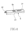
- a fourth windshield wiper arm D includes a rectangular and " ⁇ "-shaped framing portion D with a fastening hook D2 configured on the upper edge of the front end of the framing portion D1, allowing the front end of the fastening hook D2 to be curved slightly, a pointed hooking portion D3 is configured on the bottom edge of the framing portion D1, and an opening D4 is further configured on the surface of the framing portion D1.
- a fifth windshield wiper arm E includes a " ⁇ "-shaped framing portion E1 bended slightly at the rear end thereof and connected to a proper length of extension portion E2, where a step E3 is configured on the bottom edge of the front end of the framing portion E1, and an engagement portion E4 bended inward levelly is respectively configured on the two sides of the framing portion E1 behind the step E3.
- a sixth windshield wiper arm F includes a " ⁇ " -shaped framing portion F1 contracted inward obliquely at the rear end thereof and connected to a rod F2, where a step F3 is configured on the bottom edge of the front end of the framing portion F1, and an engagement portion F4 bended inward levelly is respectively configured on the two sides behind the
- a multifunctional windshield wiper connection structure of the present invention mainly includes a main seat 1, front cover 2, back cover 3, hole cover 4 and buckling element 5.
- the main seat 1, as shown in FIGS. 7A and 7B which respectively are a perspective view and bottom view, is configured with a cross hole 11 on the front end thereof, where a symmetrical sliding groove 12 extended obliquely inward is respectively configured on the two sides of the cross hole 11, and a suspension sheet 13 with a engagement hook 14 of proper elasticity at the front end thereof connected to the main seat 1 is configured in the cross hole 11.
- a groove 15 is configured behind the cross hole 11, and a fixing hole 16 passed through the main seat 1 is configured on the two sides thereof below the groove 15.
- a sliding groove 17 is configured behind the fixing hole 16, and a positioning portion 18 embossed obliquely from top to bottom is configured above the sliding groove 17.
- a symmetrical buckling channel 19 is respectively configured on the two sides of the rear edge of the main seat 1, where a step 191 is configured on a proper position of the buckling channel 19, allowing the buckling channel 19 to form a height drop.
- the two sides of the bottom edges of the main seat 1 is projected outward levelly slightly, thereby to form a symmetrical clamping portion 20, and a vertical buckling bar 21 is configured on a proper position of the center of the bottom edge.
- FIGS. 8A and 8B which respectively are a perspective view and bottom view of a front cover according to the present invention
- the front cover 2 of the present invention is configured with an opening 22 on the upper edge thereof, where a buckling hook 23 is configured on the opening 22.
- an inclined projecting rib 24 is respectively configured on the two sides of the internal vertical face of the front cover 2, and a step 25 the two sides of the bottom edge thereof, allowing the front cover 2 to be fixed to the front end of the main seat 1 by buckling the buckling hook 23 with the engagement hook 14 and by means of the positioning of the step 25 after the projecting ribs 24 are engaged with the sliding grooves 12 of the main seat 1.
- the back cover 3 of the present invention is a " ⁇ "-shaped frame, and a vertical portion 31 thereof is extended forward obliquely from top to bottom, where the bottom edge of the vertical portion 31 is formed into symmetrical inlaying sheets 32 after being bended inward levelly.
- two symmetrical blocking sheets 33 are configured on the rear side of the internal face of the back cover 3, allowing the back cover 3 to be positioned on the main seat 1 by the blocking sheet 33 and the embossed positioning portion 18 after the inlaying sheets 32 are inserted in the sliding grooves 17 and moved along the sliding groove 17 back and forth.
- the hole cover 4 of the present invention is a " ⁇ "-shaped frame, and a vertical section 41 thereof is configured with a circular projecting mass 42 corresponding to the fixing hole 16 of the main seat 1, allowing the hole cover 4 to be embedded in the groove 15 of the main seat 1 exactly, and the circular projecting mass 42 to be inserted in the fixing hole 16 exactly.
- the buckling element 5 is a " ⁇ "-shaped body, and a concave engagement portion 52 is formed on a bended section after a vertical section 51 is extended forward a proper length. Furthermore, the front of the extension section is raised slightly, and a symmetrical rib 53 is configured on the internal face of the extension section, allowing the buckling element 5 to be slid along the buckling channel 19 of the main seat 1 by inserting the rib 53 in the buckling channel 19, and fixed on the rear side of the main seat 1 through the positioning of the step 191 configured on the buckling channel 19.
- FIG 12 which is a perspective view of the present invention
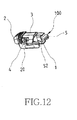
- the front cover 2, back cover 3, hole cover 4 and buckling element 5 are respectively fixed on the front, rear and upper sides of the main seat1 after the components mentioned above are assembled together to form a multifunctional windshield wiper connection structure 100, thereby allowing the installment thereof on a windshield wiper.
- some components may be detached from the connection structure 100, or recombined after the detachment according to different types of windshield wiper arms upon use so as to allow different types of windshield wiper arms to be able to be coupled to a windshield wiper, and the same multiple windshield wiper connection structure 100 can be used on different types of windshield wiper arms, thereby achieving the object of multifunctional use.
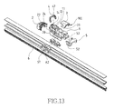
- the main seat 1 upon the assembly of the present invention, is first fixed to a retaining seat 61 of a windshield wiper 6, where the clamping portions 20 configured on the bottom edge of the main seat 1 is clamped on the two sides of the retaining seat 61, and the buckling bar 21 at the center of the bottom edge of the main seat 1 is passed through a retaining hole 62 on the upper side of the retaining seat 61 upon installment.
- the back cover 3, hole cover 4 and buckling element 5 are detached or recombined after the detachment according different requirements so as to allow different types of windshield wiper arms to be fixed to the multifunctional windshield wiper connection structure 100, thereby broadening the use scope of the multifunction windshield wiper connection structure 100, and solving the problem generated from the conventional windshield wiper that a different classification of car needs a specific connection structure.
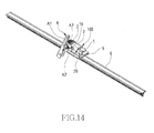
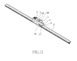
- FIGS. 14 and 15 are perspective views of a first windshield wiper arm assembling state according to the present invention
- the assembled hole cover 4 is first detached from the main seat 1 when the present invention is applied on the first windshield wiper arm A, as FIG 13 shows, allowing the fixing hole 16 of the main seat 1 to be exposed to the outside, thereby passing the fixing bar A2 of the first windshield wiper arm A through the fixing hole 16, and buckling the buckling bar A3 configured on the upper edge of the rod A1 with the upper and lateral sides of the back cover 3 so that the first windshield wiper arm A can be fixed to the multifunctional wiper connection structure 100.
- FIGS. 16 and 17 are perspective views of a second windshield wiper arm assembling state according to the present invention
- the assembled hole cover 4 and back cover 3 are detached from the main seat 1 when the present invention is applied on the second windshield wiper arm B, allowing the fixing hole 16 of the main seat 1 to be exposed to the outside, thereby passing the fixing bar B3 of the second windshield wiper arm B through the fixing hole 16 and buckling the buckling bar B4 configured on the upper edge of the rod B 1 with the upper and lateral sides of the main seat 1 so that the second windshield wiper arm B can be fixed to the multifunctional wiper connection structure 100.
- FIGS. 18 and 19 are perspective views of a third windshield wiper arm assembling state according to the present invention
- the assembled hole cover 4 and back cover 3 are detached from the main seat 1 when the present invention is applied on the third windshield wiper arm C, allowing the fastening hook C3 configured on the front end of the framing portion C2 of the third windshield wiper arm C to be fastened to the front cover 2, and the pointed hooking portion C4 configured on the bottom edge of the framing portion C2 to be engaged with the engagement portion 52 of the buckling element 5;
- the fastening hook C3 can be fastened to the front cover 2 tightly due to the positioning of the hooking portion C4 because the front end of the fastening hook C3 is curved slightly so that the third windshield wiper arm C can be fixed to the multifunctional wiper connection structure 100.
- FIGS. 20 and 21 are perspective views of a fourth windshield wiper arm assembling state according to the present invention
- the assembled hole cover 4 and back cover 3 are detached from the main seat 1 when the present invention is applied on the fourth windshield wiper arm C, allowing the fastening hook D2 configured on the front end of the framing portion D1 of the fourth windshield wiper arm D to be fastened to the front cover 2, the opening D4 to be buckled with the upper edge of the main seat 1, and the pointed hooking portion D3 configured on the bottom edge of the framing portion D1 to be engaged with the engagement portion 52 of the buckling element 5; the fastening hook D2 can be fastened to the front cover 2 tightly due to the positioning of the hooking portion D3 because the front end of the fastening hook D3 is curved slightly so that the fourth windshield wiper arm D can be fixed to the multifunctional wiper connection structure 100.
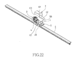
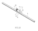
- FIGS. 22 and 23 are perspective views of a fifth windshield wiper arm assembling state according to the present invention
- the assembled back cover 3 is detached from the main seat 1 when the present invention is applied on the fifth windshield wiper arm E, allowing the framing portion E1 of the fifth windshield wiper arm E to be engaged with the main seat 1, the positioning thereof is formed by the step E3 configured on the bottom edge of the front end of the framing portion E1, and the engagement portion E4 is engaged with the sliding groove 17 of the main seat 1 so that the fifth windshield wiper arm E can be fixed to the multifunctional wiper connection structure 100.
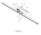
- FIGS. 24 and 25 are perspective views of a sixth windshield wiper arm assembling state according to the present invention
- the assembled back cover 3, hole cover 4 and buckling element 5 are detached from the main seat 1 when the present invention is applied on the fifth windshield wiper arm E, allowing the framing portion F1 of the sixth windshield wiper arm F to be engaged with the main seat 1, the positioning thereof is formed by the step F3 configured on the bottom edge of the front end of the framing portion F1, and the engagement portion F4 is engaged with the sliding groove 17 of the main seat 1 so that the sixth windshield wiper arm F can be fixed to the multifunctional wiper connection structure 100.
- the present invention uses the main seat matching with the components such as the front cover, back cover, hole cover and buckling element to form a multifunctional windshield wiper connection structure, allowing the single connection structure to be suitable for use on different types of windshield wiper arms. Therefore, the present invention is a practical and novelty design.
Abstract
Description
- The present invention relates to a multifunctional windshield wiper connection structure, and more particularly to a multifunctional windshield wiper connection structure through which a windshield wiper is able to be coupled to different kinds of windshield wiper arms.
- A general connection manner of a windshield wiper to a windshield wiper arm is fixing a positioning frame to a spring sheet of the windshield wiper at the center thereof and then configuring a retaining seat on the positioning frame, thereby allowing the retaining seat to be connected with the windshield wiper arm. Because such kind of conventional retaining seat need further be collocated with a connection head and is suitable for use in specific classifications of vehicles; different classifications of vehicles need be assembled with different retaining seats, causing vehicle owners much trouble upon windshield wiper installment, higher labor cost, time consumption and increased stocks cost to proprietors during the installment because of a variety of products.
- The main object of the present invention is to provide a multifunctional windshield wiper connection structure for a windshield wiper to be able to be coupled to different kinds of windshield wiper arms, allowing the same multifunctional windshield wiper connection structure to be suitable for use on different windshield wiper arms.
- To achieve the above object, the present invention proposes a multifunctional windshield wiper connection structure, including a
main seat 1, and components, such as afront cover 2,back cover 3,hole cover 4,buckling element 5, which are assembled on themain seat 1, and can be detached from themain seat 1, where themain seat 1 at least includes clampingportions 20 on the two side thereof and avertical buckling bar 21 configured on the bottom edge thereof, allowing themain seat 1 to be fixed on a retainingseat 61 of awindshield wiper 6 through the clampingportions 20 and bucklingbar 21. Whereby, the component(s) such as thefront cover 2 and/orback cover 3 and/orhole cover 4 and/orbuckling element 5 can be detached or recombined after the detachment according to different types of windshield wiper arms to provide the connection between different types of windshield wiper arms and thewindshield wiper 6, allowing the same multifunctional windshield wiper connection structure to be suitable for use on different awindshield wiper arms, thereby achieving a multiuse object. - The present invention can be more fully understood by reference to the following description and accompanying drawings, in which:
-
FIG 1 is a perspective view of a first windshield wiper arm; -
FIG 2 is a perspective view of a second windshield wiper arm; -
FIG 3 is a perspective view of a third windshield wiper arm; -
FIG 4 is a perspective view of a fourth windshield wiper arm; -
FIGS. 5A and 5B are perspective views of a fifth windshield wiper arm; -
FIGS. 6A and 6B are perspective views of a sixth windshield wiper arm; -
FIGS. 7A and 7B respectively are a perspective view and bottom view of a main seat according to the present invention; -
FIGS. 8A and 8B respectively are a perspective view and bottom view of a front cover according to the present invention; -
FIGS. 9A and 9B respectively are a perspective view and bottom view of a back cover according to the present invention; -
FIGS. 10A and 10B respectively are a perspective view and front view of a hole cover according to the present invention; -
FIGS. 11A and 11B respectively are a perspective view and bottom view of a buckling element according to the present invention; -
FIG 12 is a perspective view of the present invention; -
FIG 13 is an exploded view of the present invention; -
FIG 14 and15 are a perspective view of a first windshield wiper arm assembling state according to the present invention; -
FIGS. 16 and17 are a perspective view of a second windshield wiper arm assembling state according to the present invention; -
FIGS. 18 and19 are a perspective view of a third windshield wiper arm assembling state according to the present invention; -
FIGS. 20 and21 are a perspective view of a fourth windshield wiper arm assembling state according to the present invention; -
FIGS. 22 and23 are a perspective view of a fifth windshield wiper arm assembling state according to the present invention; and -
FIGS. 24 and25 are a perspective view of a sixth windshield wiper arm assembling state according to the present invention; - The present invention mainly designs a connection structure capable of being shared by a variety of general windshield wiper arms. To understand the objects of the present invention clearly, the structures of general currently-used windshield wiper arms are described as the following. Referring to
FIG 1 , which is a perspective and side view of a first windshield wiper arm, a windshield wiper arm A includes an approximately "Π"-shaped rod A1 with a fixing bar A2 on an end portion thereof, where a buckling bar A3 positioned above the fixing bar A2 is configured on the upper edge of the rod A1, allowing one end portion of the buckling bar A3 to be bended downward vertically. - Referring to
FIG 2 , which is a perspective view of a second windshield wiper arm, a second windshield wiper arm B includes a rod B with a frame portion B2 covered on one end portion thereof, where a fixing bar B3 is configured on the frame portion B2, and a buckling bar B4 positioned above the fixing bar B3 is configured on the upper edge of therod B 1, allowing one end portion of thebuckling bar B 4 to be bended downward vertically. - Referring to
FIG 3 , which is a perspective view of a third windshield wiper arm, a third windshield wiper arm C includes a rod C with a gradually widened and "Π"-shaped framing portion C2 configured on one end portion thereof, where a fastening hook C3 is configured on the upper edge of the front end of the framing portion C2, allowing the front end of the fastening hook C3 to be curved slightly, and a pointed hooking portion C4 is further configured on the bottom edge of the framing portion C2. - Referring to
FIG 4 , which is a perspective view of a fourth windshield wiper arm, a fourth windshield wiper arm D includes a rectangular and "Π"-shaped framing portion D with a fastening hook D2 configured on the upper edge of the front end of the framing portion D1, allowing the front end of the fastening hook D2 to be curved slightly, a pointed hooking portion D3 is configured on the bottom edge of the framing portion D1, and an opening D4 is further configured on the surface of the framing portion D1. - Referring to
FIGS. 5A and 5B , which are a perspective view of a fifth windshield wiper arm, a fifth windshield wiper arm E includes a "Π"-shaped framing portion E1 bended slightly at the rear end thereof and connected to a proper length of extension portion E2, where a step E3 is configured on the bottom edge of the front end of the framing portion E1, and an engagement portion E4 bended inward levelly is respectively configured on the two sides of the framing portion E1 behind the step E3. - Referring to
FIGS. 6A and 6B , which are a perspective view of a sixth windshield wiper arm, a sixth windshield wiper arm F includes a "Π" -shaped framing portion F1 contracted inward obliquely at the rear end thereof and connected to a rod F2, where a step F3 is configured on the bottom edge of the front end of the framing portion F1, and an engagement portion F4 bended inward levelly is respectively configured on the two sides behind the - Referring to
FIGS. 7A to 11B , a multifunctional windshield wiper connection structure of the present invention mainly includes amain seat 1,front cover 2,back cover 3,hole cover 4 andbuckling element 5. Themain seat 1, as shown inFIGS. 7A and 7B , which respectively are a perspective view and bottom view, is configured with across hole 11 on the front end thereof, where a symmetricalsliding groove 12 extended obliquely inward is respectively configured on the two sides of thecross hole 11, and asuspension sheet 13 with aengagement hook 14 of proper elasticity at the front end thereof connected to themain seat 1 is configured in thecross hole 11. In addition, agroove 15 is configured behind thecross hole 11, and afixing hole 16 passed through themain seat 1 is configured on the two sides thereof below thegroove 15. Furthermore, asliding groove 17 is configured behind thefixing hole 16, and apositioning portion 18 embossed obliquely from top to bottom is configured above thesliding groove 17. Furthermore, asymmetrical buckling channel 19 is respectively configured on the two sides of the rear edge of themain seat 1, where astep 191 is configured on a proper position of thebuckling channel 19, allowing thebuckling channel 19 to form a height drop. Furthermore, the two sides of the bottom edges of themain seat 1 is projected outward levelly slightly, thereby to form asymmetrical clamping portion 20, and avertical buckling bar 21 is configured on a proper position of the center of the bottom edge. - Referring to
FIGS. 8A and 8B , which respectively are a perspective view and bottom view of a front cover according to the present invention, thefront cover 2 of the present invention is configured with anopening 22 on the upper edge thereof, where abuckling hook 23 is configured on the opening 22. Furthermore, aninclined projecting rib 24 is respectively configured on the two sides of the internal vertical face of thefront cover 2, and astep 25 the two sides of the bottom edge thereof, allowing thefront cover 2 to be fixed to the front end of themain seat 1 by buckling thebuckling hook 23 with theengagement hook 14 and by means of the positioning of thestep 25 after the projectingribs 24 are engaged with thesliding grooves 12 of themain seat 1. - Referring to
FIGS. 9A and 9B , which respectively are a perspective view and bottom view of the back cover, theback cover 3 of the present invention is a "Π"-shaped frame, and avertical portion 31 thereof is extended forward obliquely from top to bottom, where the bottom edge of thevertical portion 31 is formed intosymmetrical inlaying sheets 32 after being bended inward levelly. Furthermore, twosymmetrical blocking sheets 33 are configured on the rear side of the internal face of theback cover 3, allowing theback cover 3 to be positioned on themain seat 1 by theblocking sheet 33 and the embossedpositioning portion 18 after theinlaying sheets 32 are inserted in thesliding grooves 17 and moved along thesliding groove 17 back and forth.. - Referring to
FIGS. 10A and 10B , which respectively are a perspective view and front view of the hole cover, thehole cover 4 of the present invention is a "Π"-shaped frame, and avertical section 41 thereof is configured with a circular projectingmass 42 corresponding to thefixing hole 16 of themain seat 1, allowing thehole cover 4 to be embedded in thegroove 15 of themain seat 1 exactly, and the circular projectingmass 42 to be inserted in thefixing hole 16 exactly. - Referring to
FIGS. 11A and 11B , which respectively are a perspective view and bottom view of the buckling element, the bucklingelement 5 is a "Π"-shaped body, and aconcave engagement portion 52 is formed on a bended section after avertical section 51 is extended forward a proper length. Furthermore, the front of the extension section is raised slightly, and asymmetrical rib 53 is configured on the internal face of the extension section, allowing the bucklingelement 5 to be slid along the bucklingchannel 19 of themain seat 1 by inserting therib 53 in the bucklingchannel 19, and fixed on the rear side of themain seat 1 through the positioning of thestep 191 configured on the bucklingchannel 19. - Referring to
FIG 12 , which is a perspective view of the present invention, thefront cover 2,back cover 3,hole cover 4 and bucklingelement 5 are respectively fixed on the front, rear and upper sides of the main seat1 after the components mentioned above are assembled together to form a multifunctional windshieldwiper connection structure 100, thereby allowing the installment thereof on a windshield wiper. Furthermore, some components may be detached from theconnection structure 100, or recombined after the detachment according to different types of windshield wiper arms upon use so as to allow different types of windshield wiper arms to be able to be coupled to a windshield wiper, and the same multiple windshieldwiper connection structure 100 can be used on different types of windshield wiper arms, thereby achieving the object of multifunctional use. - Referring to
FIG 13 , which is an exploded view of the present invention, upon the assembly of the present invention, themain seat 1 is first fixed to a retainingseat 61 of awindshield wiper 6, where the clampingportions 20 configured on the bottom edge of themain seat 1 is clamped on the two sides of the retainingseat 61, and the bucklingbar 21 at the center of the bottom edge of themain seat 1 is passed through a retaininghole 62 on the upper side of the retainingseat 61 upon installment. Thus, theback cover 3,hole cover 4 and bucklingelement 5 are detached or recombined after the detachment according different requirements so as to allow different types of windshield wiper arms to be fixed to the multifunctional windshieldwiper connection structure 100, thereby broadening the use scope of the multifunction windshieldwiper connection structure 100, and solving the problem generated from the conventional windshield wiper that a different classification of car needs a specific connection structure. - Referring to
FIGS. 14 and15 , which are perspective views of a first windshield wiper arm assembling state according to the present invention, the assembledhole cover 4 is first detached from themain seat 1 when the present invention is applied on the first windshield wiper arm A, asFIG 13 shows, allowing the fixinghole 16 of themain seat 1 to be exposed to the outside, thereby passing the fixing bar A2 of the first windshield wiper arm A through the fixinghole 16, and buckling the buckling bar A3 configured on the upper edge of the rod A1 with the upper and lateral sides of theback cover 3 so that the first windshield wiper arm A can be fixed to the multifunctionalwiper connection structure 100. - Referring to
FIGS. 16 and17 , which are perspective views of a second windshield wiper arm assembling state according to the present invention, the assembledhole cover 4 andback cover 3 are detached from themain seat 1 when the present invention is applied on the second windshield wiper arm B, allowing the fixinghole 16 of themain seat 1 to be exposed to the outside, thereby passing the fixing bar B3 of the second windshield wiper arm B through the fixinghole 16 and buckling the buckling bar B4 configured on the upper edge of therod B 1 with the upper and lateral sides of themain seat 1 so that the second windshield wiper arm B can be fixed to the multifunctionalwiper connection structure 100. - Referring to
FIGS. 18 and19 , which are perspective views of a third windshield wiper arm assembling state according to the present invention, the assembledhole cover 4 andback cover 3 are detached from themain seat 1 when the present invention is applied on the third windshield wiper arm C, allowing the fastening hook C3 configured on the front end of the framing portion C2 of the third windshield wiper arm C to be fastened to thefront cover 2, and the pointed hooking portion C4 configured on the bottom edge of the framing portion C2 to be engaged with theengagement portion 52 of the bucklingelement 5; the fastening hook C3 can be fastened to thefront cover 2 tightly due to the positioning of the hooking portion C4 because the front end of the fastening hook C3 is curved slightly so that the third windshield wiper arm C can be fixed to the multifunctionalwiper connection structure 100. - Referring to
FIGS. 20 and21 , which are perspective views of a fourth windshield wiper arm assembling state according to the present invention, the assembledhole cover 4 andback cover 3 are detached from themain seat 1 when the present invention is applied on the fourth windshield wiper arm C, allowing the fastening hook D2 configured on the front end of the framing portion D1 of the fourth windshield wiper arm D to be fastened to thefront cover 2, the opening D4 to be buckled with the upper edge of themain seat 1, and the pointed hooking portion D3 configured on the bottom edge of the framing portion D1 to be engaged with theengagement portion 52 of the bucklingelement 5; the fastening hook D2 can be fastened to thefront cover 2 tightly due to the positioning of the hooking portion D3 because the front end of the fastening hook D3 is curved slightly so that the fourth windshield wiper arm D can be fixed to the multifunctionalwiper connection structure 100. - Referring to
FIGS. 22 and23 , which are perspective views of a fifth windshield wiper arm assembling state according to the present invention, the assembled backcover 3 is detached from themain seat 1 when the present invention is applied on the fifth windshield wiper arm E, allowing the framing portion E1 of the fifth windshield wiper arm E to be engaged with themain seat 1, the positioning thereof is formed by the step E3 configured on the bottom edge of the front end of the framing portion E1, and the engagement portion E4 is engaged with the slidinggroove 17 of themain seat 1 so that the fifth windshield wiper arm E can be fixed to the multifunctionalwiper connection structure 100. - Referring to
FIGS. 24 and25 , which are perspective views of a sixth windshield wiper arm assembling state according to the present invention, the assembled backcover 3,hole cover 4 and bucklingelement 5 are detached from themain seat 1 when the present invention is applied on the fifth windshield wiper arm E, allowing the framing portion F1 of the sixth windshield wiper arm F to be engaged with themain seat 1, the positioning thereof is formed by the step F3 configured on the bottom edge of the front end of the framing portion F1, and the engagement portion F4 is engaged with the slidinggroove 17 of themain seat 1 so that the sixth windshield wiper arm F can be fixed to the multifunctionalwiper connection structure 100. - Additional advantages and modifications will readily occur to those skilled in the art. Therefore, the invention in its broader aspects is not limited to the specific details and representative embodiments shown and described herein. Accordingly, various modifications may be made without departing from the spirit or scope of the general inventive concept as defined by the appended claims and their equivalents.
- To sum up, the present invention uses the main seat matching with the components such as the front cover, back cover, hole cover and buckling element to form a multifunctional windshield wiper connection structure, allowing the single connection structure to be suitable for use on different types of windshield wiper arms. Therefore, the present invention is a practical and novelty design.
Claims (5)
- A multifunctional windshield wiper connection structure, comprising:a main seat (1), configured with a cross hole (11) on a front end thereof, a symmetrical sliding groove (12) extended obliquely inward being respectively configured on two sides of said cross hole (11),a groove (15) being configured behind said cross hole (11), a fixing hole (16) passed through the main seat (1) being configured on two sides thereof below said groove (15), a sliding groove (17) being configured behind said fixing hole (16), a symmetrical buckling channel (19) being respectively configured on two sides of a rear edge of said main seat (1), a clamping portion (20) being configure on a bottom edge of said main seat (1), and a buckling bar 21 for the fixation thereof to a retaining seat (61) of a windshield wiper (6) being configured on a proper position of a center of said bottom edge;a front cover (2), configured with an inclined projecting rib (24) respectively positioned on two sides of an internal face thereof, said front cover (2) being fixed to a front end of said main seat (1) after said projecting rib (24) is engaged with said sliding groove (12) and slid inward;a back cover (3), being a "Π"-shaped frame, a bottom edge of a vertical portion (31) thereof being bended inward levelly to form symmetrical inlaying sheets (32), said back cover (3) being fixed on a upper side of said main seat (1) by inserting the inlaying sheets (32) into said sliding groove (17) of said main seat (1);a hole cover (4), being a "Π"-shaped frame, a vertical section (41) thereof being configured with a circular projecting mass (42) corresponding to said fixing hole (16) of said main seat (1), allowing said hole cover (4) to be embedded in said groove (15) of said main seat (1) exactly, and said circular projecting mass (42) to be inserted in said fixing hole (16) exactly; anda buckling element (5), being a "Π"-shaped body, and a concave engagement portion (52) being formed on a bended section after a vertical section (51) is extended forward a proper length, a symmetrical rib (53) being configured on a respective internal face of said extension section, said buckling element (5) being fixed on a rear side of said main seat (1) by inserting said rib (53) in said buckling channel (19);whereby, some of said components are detached from said connection structure, or recombined after the detachment according to different types of windshield wiper arms upon use so as to allow different types of windshield wiper arms to be able to be coupled to a windshield wiper, and the same multiple windshield wiper connection structure is capable of being used on different windshield wiper arms.
- The connection structure according to claim 1, wherein an elastic engagement hook (14) is configured on a front of said cross hole (11) of said main seat (1), and an opening (22) an upper edge of said front cover (2), wherein a buckling hook (23) is configured on said opening (2), allowing said front cover (2) to be positioned by buckling said buckling hook (23) with said engagement hook (14) after said projecting ribs (24) is engaged with said sliding groove (12).
- The connection structure according to claim 1, wherein a step (25) is configured on a bottom edge of said front cover (2), allowing said front cover (2) to be positioned through said step (25) while being fixed to said front end of said main seat (1).
- The connection structure according to claim 1, wherein an embossed positioning portion (18) is configured on said main seat (1) above each said sliding groove (17), and symmetrical blocking sheets (33) are configured on an inner edge at a rear side of said back cover (3), allowing said inlaying sheet (32) of said back cover (3) to be positioned through said blocking sheet (33) and corresponding embossed positioning portion (18) while being inserted in said corresponding sliding groove (17).
- The connection structure according to claim 1, wherein a step 191 is configured on a proper position of buckling channel (19) on each side of a rear edge of said main seat (1), allowing said buckling element (5) to be positioned through said step (191) configured on said buckling channel (19) when said rib (53) is inserted in said buckling channel (19).
Priority Applications (1)
| Application Number | Priority Date | Filing Date | Title |
|---|---|---|---|
| EP14152365.4A EP2899078B1 (en) | 2014-01-24 | 2014-01-24 | Multifunctional windshield wiper connection structure |
Applications Claiming Priority (1)
| Application Number | Priority Date | Filing Date | Title |
|---|---|---|---|
| EP14152365.4A EP2899078B1 (en) | 2014-01-24 | 2014-01-24 | Multifunctional windshield wiper connection structure |
Publications (2)
| Publication Number | Publication Date |
|---|---|
| EP2899078A1 true EP2899078A1 (en) | 2015-07-29 |
| EP2899078B1 EP2899078B1 (en) | 2016-09-07 |
Family
ID=50000813
Family Applications (1)
| Application Number | Title | Priority Date | Filing Date |
|---|---|---|---|
| EP14152365.4A Active EP2899078B1 (en) | 2014-01-24 | 2014-01-24 | Multifunctional windshield wiper connection structure |
Country Status (1)
| Country | Link |
|---|---|
| EP (1) | EP2899078B1 (en) |
Cited By (2)
| Publication number | Priority date | Publication date | Assignee | Title |
|---|---|---|---|---|
| EP3168093A1 (en) * | 2015-11-13 | 2017-05-17 | Valeo Systèmes d'Essuyage | Adapter for a motor vehicle windscreen wiper |
| FR3043614A1 (en) * | 2015-11-13 | 2017-05-19 | Valeo Systemes Dessuyage | ADAPTER FOR A WINDSCREEN WIPER OF A MOTOR VEHICLE |
Citations (4)
| Publication number | Priority date | Publication date | Assignee | Title |
|---|---|---|---|---|
| EP1995130A2 (en) * | 2007-05-21 | 2008-11-26 | ADM21 Co., Ltd. | Wiper blade |
| EP2360070A1 (en) * | 2010-02-12 | 2011-08-24 | Unipoint Electric MFG. Co., Ltd. | Wiper connector |
| EP2465739A2 (en) * | 2010-12-14 | 2012-06-20 | Cap Corporation | Wiper device |
| DE202012102614U1 (en) * | 2012-07-13 | 2012-08-14 | Xiamen Fuke Car Accessories Co., Ltd. | Connecting device for windscreen wipers |
-
2014
- 2014-01-24 EP EP14152365.4A patent/EP2899078B1/en active Active
Patent Citations (4)
| Publication number | Priority date | Publication date | Assignee | Title |
|---|---|---|---|---|
| EP1995130A2 (en) * | 2007-05-21 | 2008-11-26 | ADM21 Co., Ltd. | Wiper blade |
| EP2360070A1 (en) * | 2010-02-12 | 2011-08-24 | Unipoint Electric MFG. Co., Ltd. | Wiper connector |
| EP2465739A2 (en) * | 2010-12-14 | 2012-06-20 | Cap Corporation | Wiper device |
| DE202012102614U1 (en) * | 2012-07-13 | 2012-08-14 | Xiamen Fuke Car Accessories Co., Ltd. | Connecting device for windscreen wipers |
Cited By (4)
| Publication number | Priority date | Publication date | Assignee | Title |
|---|---|---|---|---|
| EP3168093A1 (en) * | 2015-11-13 | 2017-05-17 | Valeo Systèmes d'Essuyage | Adapter for a motor vehicle windscreen wiper |
| FR3043614A1 (en) * | 2015-11-13 | 2017-05-19 | Valeo Systemes Dessuyage | ADAPTER FOR A WINDSCREEN WIPER OF A MOTOR VEHICLE |
| FR3043615A1 (en) * | 2015-11-13 | 2017-05-19 | Valeo Systemes Dessuyage | ADAPTER FOR A WINDSCREEN WIPER OF A MOTOR VEHICLE |
| US10518753B2 (en) | 2015-11-13 | 2019-12-31 | Valeo Systèmes d'Essuyage | Adapter for a motor vehicle windscreen wiper |
Also Published As
| Publication number | Publication date |
|---|---|
| EP2899078B1 (en) | 2016-09-07 |
Similar Documents
| Publication | Publication Date | Title |
|---|---|---|
| KR101484062B1 (en) | Flat wiper blade | |
| US8528155B2 (en) | Structure of windshield wiper | |
| US7698775B2 (en) | Windshield wiper assembly having a body made of spring steel | |
| US9505380B2 (en) | Windshield wiper connector and assembly | |
| US20120180246A1 (en) | Windshield wiper blade assembly | |
| WO2017201458A1 (en) | Windshield wiper connector | |
| EP1842716A2 (en) | Child car seat device with wing components | |
| US7703500B2 (en) | Bracket and head rail assembly | |
| JP6267356B2 (en) | Parts mounting structure | |
| US8695682B2 (en) | Pull bar device for a sunshade assembly | |
| US20180319350A1 (en) | Automobile Accessory Mounting Support | |
| EP2899078B1 (en) | Multifunctional windshield wiper connection structure | |
| KR200472150Y1 (en) | An air vent knob for a vehicle | |
| US7980613B2 (en) | Rear garnish clip | |
| US10137846B2 (en) | Connector used for connecting vehicle parts and a vehicle employing the same | |
| US8573282B2 (en) | Side bar device for a sunshade assembly | |
| US20180153300A1 (en) | Ironing board leg lock | |
| JP6243701B2 (en) | Mounting member mounting structure | |
| US20180370456A1 (en) | Connection assemblies in a vehicle | |
| JP6337302B2 (en) | Vehicle front bumper | |
| US10414367B2 (en) | Tow hook cover assembly for an automotive bumper fascia | |
| JP5792081B2 (en) | Vehicle seat | |
| KR101616976B1 (en) | wire insert clip of seat back frame for vehicle | |
| JP6027526B2 (en) | Vehicle visor | |
| CN108454529B (en) | Interior trim part for vehicle |
Legal Events
| Date | Code | Title | Description |
|---|---|---|---|
| PUAI | Public reference made under article 153(3) epc to a published international application that has entered the european phase |
Free format text: ORIGINAL CODE: 0009012 |
|
| 17P | Request for examination filed |
Effective date: 20140124 |
|
| AK | Designated contracting states |
Kind code of ref document: A1 Designated state(s): AL AT BE BG CH CY CZ DE DK EE ES FI FR GB GR HR HU IE IS IT LI LT LU LV MC MK MT NL NO PL PT RO RS SE SI SK SM TR |
|
| AX | Request for extension of the european patent |
Extension state: BA ME |
|
| GRAP | Despatch of communication of intention to grant a patent |
Free format text: ORIGINAL CODE: EPIDOSNIGR1 |
|
| INTG | Intention to grant announced |
Effective date: 20160504 |
|
| GRAS | Grant fee paid |
Free format text: ORIGINAL CODE: EPIDOSNIGR3 |
|
| GRAA | (expected) grant |
Free format text: ORIGINAL CODE: 0009210 |
|
| AK | Designated contracting states |
Kind code of ref document: B1 Designated state(s): AL AT BE BG CH CY CZ DE DK EE ES FI FR GB GR HR HU IE IS IT LI LT LU LV MC MK MT NL NO PL PT RO RS SE SI SK SM TR |
|
| REG | Reference to a national code |
Ref country code: GB Ref legal event code: FG4D |
|
| REG | Reference to a national code |
Ref country code: CH Ref legal event code: EP |
|
| REG | Reference to a national code |
Ref country code: IE Ref legal event code: FG4D |
|
| REG | Reference to a national code |
Ref country code: AT Ref legal event code: REF Ref document number: 826535 Country of ref document: AT Kind code of ref document: T Effective date: 20161015 |
|
| REG | Reference to a national code |
Ref country code: DE Ref legal event code: R096 Ref document number: 602014003433 Country of ref document: DE |
|
| REG | Reference to a national code |
Ref country code: LT Ref legal event code: MG4D |
|
| REG | Reference to a national code |
Ref country code: NL Ref legal event code: MP Effective date: 20160907 |
|
| REG | Reference to a national code |
Ref country code: FR Ref legal event code: PLFP Year of fee payment: 4 |
|
| PG25 | Lapsed in a contracting state [announced via postgrant information from national office to epo] |
Ref country code: RS Free format text: LAPSE BECAUSE OF FAILURE TO SUBMIT A TRANSLATION OF THE DESCRIPTION OR TO PAY THE FEE WITHIN THE PRESCRIBED TIME-LIMIT Effective date: 20160907 Ref country code: LT Free format text: LAPSE BECAUSE OF FAILURE TO SUBMIT A TRANSLATION OF THE DESCRIPTION OR TO PAY THE FEE WITHIN THE PRESCRIBED TIME-LIMIT Effective date: 20160907 Ref country code: NO Free format text: LAPSE BECAUSE OF FAILURE TO SUBMIT A TRANSLATION OF THE DESCRIPTION OR TO PAY THE FEE WITHIN THE PRESCRIBED TIME-LIMIT Effective date: 20161207 Ref country code: HR Free format text: LAPSE BECAUSE OF FAILURE TO SUBMIT A TRANSLATION OF THE DESCRIPTION OR TO PAY THE FEE WITHIN THE PRESCRIBED TIME-LIMIT Effective date: 20160907 Ref country code: FI Free format text: LAPSE BECAUSE OF FAILURE TO SUBMIT A TRANSLATION OF THE DESCRIPTION OR TO PAY THE FEE WITHIN THE PRESCRIBED TIME-LIMIT Effective date: 20160907 |
|
| REG | Reference to a national code |
Ref country code: AT Ref legal event code: MK05 Ref document number: 826535 Country of ref document: AT Kind code of ref document: T Effective date: 20160907 |
|
| PG25 | Lapsed in a contracting state [announced via postgrant information from national office to epo] |
Ref country code: SE Free format text: LAPSE BECAUSE OF FAILURE TO SUBMIT A TRANSLATION OF THE DESCRIPTION OR TO PAY THE FEE WITHIN THE PRESCRIBED TIME-LIMIT Effective date: 20160907 Ref country code: GR Free format text: LAPSE BECAUSE OF FAILURE TO SUBMIT A TRANSLATION OF THE DESCRIPTION OR TO PAY THE FEE WITHIN THE PRESCRIBED TIME-LIMIT Effective date: 20161208 Ref country code: LV Free format text: LAPSE BECAUSE OF FAILURE TO SUBMIT A TRANSLATION OF THE DESCRIPTION OR TO PAY THE FEE WITHIN THE PRESCRIBED TIME-LIMIT Effective date: 20160907 Ref country code: ES Free format text: LAPSE BECAUSE OF FAILURE TO SUBMIT A TRANSLATION OF THE DESCRIPTION OR TO PAY THE FEE WITHIN THE PRESCRIBED TIME-LIMIT Effective date: 20160907 Ref country code: NL Free format text: LAPSE BECAUSE OF FAILURE TO SUBMIT A TRANSLATION OF THE DESCRIPTION OR TO PAY THE FEE WITHIN THE PRESCRIBED TIME-LIMIT Effective date: 20160907 |
|
| PG25 | Lapsed in a contracting state [announced via postgrant information from national office to epo] |
Ref country code: EE Free format text: LAPSE BECAUSE OF FAILURE TO SUBMIT A TRANSLATION OF THE DESCRIPTION OR TO PAY THE FEE WITHIN THE PRESCRIBED TIME-LIMIT Effective date: 20160907 Ref country code: RO Free format text: LAPSE BECAUSE OF FAILURE TO SUBMIT A TRANSLATION OF THE DESCRIPTION OR TO PAY THE FEE WITHIN THE PRESCRIBED TIME-LIMIT Effective date: 20160907 |
|
| PG25 | Lapsed in a contracting state [announced via postgrant information from national office to epo] |
Ref country code: IS Free format text: LAPSE BECAUSE OF FAILURE TO SUBMIT A TRANSLATION OF THE DESCRIPTION OR TO PAY THE FEE WITHIN THE PRESCRIBED TIME-LIMIT Effective date: 20170107 Ref country code: SK Free format text: LAPSE BECAUSE OF FAILURE TO SUBMIT A TRANSLATION OF THE DESCRIPTION OR TO PAY THE FEE WITHIN THE PRESCRIBED TIME-LIMIT Effective date: 20160907 Ref country code: PL Free format text: LAPSE BECAUSE OF FAILURE TO SUBMIT A TRANSLATION OF THE DESCRIPTION OR TO PAY THE FEE WITHIN THE PRESCRIBED TIME-LIMIT Effective date: 20160907 Ref country code: BG Free format text: LAPSE BECAUSE OF FAILURE TO SUBMIT A TRANSLATION OF THE DESCRIPTION OR TO PAY THE FEE WITHIN THE PRESCRIBED TIME-LIMIT Effective date: 20161207 Ref country code: CZ Free format text: LAPSE BECAUSE OF FAILURE TO SUBMIT A TRANSLATION OF THE DESCRIPTION OR TO PAY THE FEE WITHIN THE PRESCRIBED TIME-LIMIT Effective date: 20160907 Ref country code: AT Free format text: LAPSE BECAUSE OF FAILURE TO SUBMIT A TRANSLATION OF THE DESCRIPTION OR TO PAY THE FEE WITHIN THE PRESCRIBED TIME-LIMIT Effective date: 20160907 Ref country code: SM Free format text: LAPSE BECAUSE OF FAILURE TO SUBMIT A TRANSLATION OF THE DESCRIPTION OR TO PAY THE FEE WITHIN THE PRESCRIBED TIME-LIMIT Effective date: 20160907 Ref country code: BE Free format text: LAPSE BECAUSE OF FAILURE TO SUBMIT A TRANSLATION OF THE DESCRIPTION OR TO PAY THE FEE WITHIN THE PRESCRIBED TIME-LIMIT Effective date: 20160907 Ref country code: PT Free format text: LAPSE BECAUSE OF FAILURE TO SUBMIT A TRANSLATION OF THE DESCRIPTION OR TO PAY THE FEE WITHIN THE PRESCRIBED TIME-LIMIT Effective date: 20170109 |
|
| REG | Reference to a national code |
Ref country code: DE Ref legal event code: R097 Ref document number: 602014003433 Country of ref document: DE |
|
| PG25 | Lapsed in a contracting state [announced via postgrant information from national office to epo] |
Ref country code: IT Free format text: LAPSE BECAUSE OF FAILURE TO SUBMIT A TRANSLATION OF THE DESCRIPTION OR TO PAY THE FEE WITHIN THE PRESCRIBED TIME-LIMIT Effective date: 20160907 |
|
| PLBE | No opposition filed within time limit |
Free format text: ORIGINAL CODE: 0009261 |
|
| STAA | Information on the status of an ep patent application or granted ep patent |
Free format text: STATUS: NO OPPOSITION FILED WITHIN TIME LIMIT |
|
| PG25 | Lapsed in a contracting state [announced via postgrant information from national office to epo] |
Ref country code: DK Free format text: LAPSE BECAUSE OF FAILURE TO SUBMIT A TRANSLATION OF THE DESCRIPTION OR TO PAY THE FEE WITHIN THE PRESCRIBED TIME-LIMIT Effective date: 20160907 |
|
| 26N | No opposition filed |
Effective date: 20170608 |
|
| PG25 | Lapsed in a contracting state [announced via postgrant information from national office to epo] |
Ref country code: SI Free format text: LAPSE BECAUSE OF FAILURE TO SUBMIT A TRANSLATION OF THE DESCRIPTION OR TO PAY THE FEE WITHIN THE PRESCRIBED TIME-LIMIT Effective date: 20160907 |
|
| REG | Reference to a national code |
Ref country code: CH Ref legal event code: PL |
|
| PG25 | Lapsed in a contracting state [announced via postgrant information from national office to epo] |
Ref country code: MC Free format text: LAPSE BECAUSE OF FAILURE TO SUBMIT A TRANSLATION OF THE DESCRIPTION OR TO PAY THE FEE WITHIN THE PRESCRIBED TIME-LIMIT Effective date: 20160907 |
|
| PG25 | Lapsed in a contracting state [announced via postgrant information from national office to epo] |
Ref country code: LI Free format text: LAPSE BECAUSE OF NON-PAYMENT OF DUE FEES Effective date: 20170131 Ref country code: CH Free format text: LAPSE BECAUSE OF NON-PAYMENT OF DUE FEES Effective date: 20170131 |
|
| REG | Reference to a national code |
Ref country code: IE Ref legal event code: MM4A |
|
| PG25 | Lapsed in a contracting state [announced via postgrant information from national office to epo] |
Ref country code: LU Free format text: LAPSE BECAUSE OF NON-PAYMENT OF DUE FEES Effective date: 20170124 |
|
| REG | Reference to a national code |
Ref country code: FR Ref legal event code: PLFP Year of fee payment: 5 |
|
| PG25 | Lapsed in a contracting state [announced via postgrant information from national office to epo] |
Ref country code: IE Free format text: LAPSE BECAUSE OF NON-PAYMENT OF DUE FEES Effective date: 20170124 |
|
| GBPC | Gb: european patent ceased through non-payment of renewal fee |
Effective date: 20180124 |
|
| PG25 | Lapsed in a contracting state [announced via postgrant information from national office to epo] |
Ref country code: MT Free format text: LAPSE BECAUSE OF NON-PAYMENT OF DUE FEES Effective date: 20170124 |
|
| PG25 | Lapsed in a contracting state [announced via postgrant information from national office to epo] |
Ref country code: AL Free format text: LAPSE BECAUSE OF FAILURE TO SUBMIT A TRANSLATION OF THE DESCRIPTION OR TO PAY THE FEE WITHIN THE PRESCRIBED TIME-LIMIT Effective date: 20160907 |
|
| PG25 | Lapsed in a contracting state [announced via postgrant information from national office to epo] |
Ref country code: GB Free format text: LAPSE BECAUSE OF NON-PAYMENT OF DUE FEES Effective date: 20180124 |
|
| PG25 | Lapsed in a contracting state [announced via postgrant information from national office to epo] |
Ref country code: HU Free format text: LAPSE BECAUSE OF FAILURE TO SUBMIT A TRANSLATION OF THE DESCRIPTION OR TO PAY THE FEE WITHIN THE PRESCRIBED TIME-LIMIT; INVALID AB INITIO Effective date: 20140124 |
|
| PG25 | Lapsed in a contracting state [announced via postgrant information from national office to epo] |
Ref country code: CY Free format text: LAPSE BECAUSE OF FAILURE TO SUBMIT A TRANSLATION OF THE DESCRIPTION OR TO PAY THE FEE WITHIN THE PRESCRIBED TIME-LIMIT Effective date: 20160907 |
|
| PG25 | Lapsed in a contracting state [announced via postgrant information from national office to epo] |
Ref country code: MK Free format text: LAPSE BECAUSE OF FAILURE TO SUBMIT A TRANSLATION OF THE DESCRIPTION OR TO PAY THE FEE WITHIN THE PRESCRIBED TIME-LIMIT Effective date: 20160907 |
|
| PG25 | Lapsed in a contracting state [announced via postgrant information from national office to epo] |
Ref country code: TR Free format text: LAPSE BECAUSE OF FAILURE TO SUBMIT A TRANSLATION OF THE DESCRIPTION OR TO PAY THE FEE WITHIN THE PRESCRIBED TIME-LIMIT Effective date: 20160907 |
|
| PGFP | Annual fee paid to national office [announced via postgrant information from national office to epo] |
Ref country code: FR Payment date: 20230124 Year of fee payment: 10 |
|
| PGFP | Annual fee paid to national office [announced via postgrant information from national office to epo] |
Ref country code: DE Payment date: 20221208 Year of fee payment: 10 |