EP1842698A1 - Fahrzeugluftreifen mit einer pannenverhindernden Einlage - Google Patents
Fahrzeugluftreifen mit einer pannenverhindernden Einlage Download PDFInfo
- Publication number
- EP1842698A1 EP1842698A1 EP07102675A EP07102675A EP1842698A1 EP 1842698 A1 EP1842698 A1 EP 1842698A1 EP 07102675 A EP07102675 A EP 07102675A EP 07102675 A EP07102675 A EP 07102675A EP 1842698 A1 EP1842698 A1 EP 1842698A1
- Authority
- EP
- European Patent Office
- Prior art keywords
- insert
- layer
- vehicle tire
- tire according
- inner layer
- Prior art date
- Legal status (The legal status is an assumption and is not a legal conclusion. Google has not performed a legal analysis and makes no representation as to the accuracy of the status listed.)
- Granted
Links
- 230000015556 catabolic process Effects 0.000 title description 3
- 239000004809 Teflon Substances 0.000 claims abstract description 6
- 229920006362 Teflon® Polymers 0.000 claims abstract description 6
- 229920001971 elastomer Polymers 0.000 claims description 17
- 239000000463 material Substances 0.000 claims description 17
- 230000000149 penetrating effect Effects 0.000 claims description 17
- 239000011159 matrix material Substances 0.000 claims description 11
- 239000004753 textile Substances 0.000 claims description 9
- 239000004744 fabric Substances 0.000 claims description 8
- 239000011248 coating agent Substances 0.000 claims description 7
- 238000000576 coating method Methods 0.000 claims description 7
- 229920002292 Nylon 6 Polymers 0.000 claims description 5
- 150000001875 compounds Chemical class 0.000 claims description 5
- 229910052751 metal Inorganic materials 0.000 claims description 4
- 239000002184 metal Substances 0.000 claims description 4
- 230000001681 protective effect Effects 0.000 claims description 4
- 239000004677 Nylon Substances 0.000 claims description 3
- 239000004952 Polyamide Substances 0.000 claims description 3
- 229920002334 Spandex Polymers 0.000 claims description 3
- 229920001778 nylon Polymers 0.000 claims description 3
- 229920002647 polyamide Polymers 0.000 claims description 3
- 229920000642 polymer Polymers 0.000 claims description 3
- 239000004760 aramid Substances 0.000 claims description 2
- 229920003235 aromatic polyamide Polymers 0.000 claims description 2
- 239000004816 latex Substances 0.000 claims description 2
- 229920000126 latex Polymers 0.000 claims description 2
- 229920002302 Nylon 6,6 Polymers 0.000 claims 1
- 239000000853 adhesive Substances 0.000 claims 1
- 230000001070 adhesive effect Effects 0.000 claims 1
- 239000010410 layer Substances 0.000 description 80
- 239000011324 bead Substances 0.000 description 9
- 230000035515 penetration Effects 0.000 description 6
- 238000007789 sealing Methods 0.000 description 5
- 229910000831 Steel Inorganic materials 0.000 description 4
- 230000000284 resting effect Effects 0.000 description 4
- 239000010959 steel Substances 0.000 description 4
- 239000000126 substance Substances 0.000 description 4
- 238000013459 approach Methods 0.000 description 3
- 239000000565 sealant Substances 0.000 description 3
- 238000004073 vulcanization Methods 0.000 description 3
- 238000010276 construction Methods 0.000 description 2
- 150000002739 metals Chemical class 0.000 description 2
- 238000010521 absorption reaction Methods 0.000 description 1
- 239000002131 composite material Substances 0.000 description 1
- 230000006378 damage Effects 0.000 description 1
- 230000001419 dependent effect Effects 0.000 description 1
- 239000007788 liquid Substances 0.000 description 1
- 238000004519 manufacturing process Methods 0.000 description 1
- 229910001092 metal group alloy Inorganic materials 0.000 description 1
- 238000000034 method Methods 0.000 description 1
- 239000000203 mixture Substances 0.000 description 1
- 230000004048 modification Effects 0.000 description 1
- 238000012986 modification Methods 0.000 description 1
- 229920000728 polyester Polymers 0.000 description 1
- 230000001012 protector Effects 0.000 description 1
- 230000002787 reinforcement Effects 0.000 description 1
- 230000003014 reinforcing effect Effects 0.000 description 1
- 239000002356 single layer Substances 0.000 description 1
- 208000008918 voyeurism Diseases 0.000 description 1
Images


Classifications
-
- B—PERFORMING OPERATIONS; TRANSPORTING
- B60—VEHICLES IN GENERAL
- B60C—VEHICLE TYRES; TYRE INFLATION; TYRE CHANGING; CONNECTING VALVES TO INFLATABLE ELASTIC BODIES IN GENERAL; DEVICES OR ARRANGEMENTS RELATED TO TYRES
- B60C19/00—Tyre parts or constructions not otherwise provided for
- B60C19/12—Puncture preventing arrangements
-
- B—PERFORMING OPERATIONS; TRANSPORTING
- B60—VEHICLES IN GENERAL
- B60C—VEHICLE TYRES; TYRE INFLATION; TYRE CHANGING; CONNECTING VALVES TO INFLATABLE ELASTIC BODIES IN GENERAL; DEVICES OR ARRANGEMENTS RELATED TO TYRES
- B60C9/00—Reinforcements or ply arrangement of pneumatic tyres
- B60C9/02—Carcasses
- B60C9/12—Carcasses built-up with rubberised layers of discrete fibres or filaments
Definitions
- the invention relates to a pneumatic vehicle tire, consisting of a profiled tread, a multi-layer belt, an airtight inner layer, an at least single-layer carcass, tensile core, sidewalls and a protective liner to prevent air pressure loss due to leakage of the inner layer by penetrating into the tire from the outside Article, wherein the insert is arranged closed below the profiled tread over the circumference and has at least the width of the tire contact patch.
- Puncture proof pneumatic vehicle tires are well known. There are two different approaches to make a pneumatic vehicle tire puncture proof. In the event of a breakdown, the first approach focuses on emergency running properties with, for example, reinforced self-supporting sidewall constructions.
- the further approach is to prevent a loss of compressed air and thus the breakdown case from the outset.
- a self-sealing insert on the axially inner side of the inner layer of an already vulcanized tire.
- the self-sealing insert has a sponge-like layer containing liquid sealant.
- a puncture channel of a penetrated to self-sealing layer article is filled by the sealant contained in this position.
- the disadvantage is that the insert must be arranged in a further, subsequent to the tire structure and vulcanization step on the tire. This is time consuming and expensive. The insert itself is expensive to manufacture.
- the sealant such a self-sealing layer only leaks up to a seal certain diameter. For larger items, the seal no longer works reliably. In the case of objects penetrating deeply into the tire, the airtight inner layer is in any case injured, which leads to a weak point in the tire despite self-sealing. In addition, the driving characteristics can be changed.
- a tire with this insert should be inexpensive and easy to produce and should continue to prevent a puncture of the airtight running inner layer of the tire by an externally penetrating into the tire object. Furthermore, the arrangement of this deposit should not change the driving performance of the tire over tires without insert.
- the object is achieved by arranging the insert between the inner layer and the carcass for preventing puncturing of the inner layer such that at least the radially outer surface of the insert consists of a material or a coating which does not adhere to the layer arranged above the insert and the insert is flexible and designed to deflect when penetrating objects easily deformable and stretchable.
- the insert disposed between the inner layer and the carcass does not chemically adhere to the layer arranged above the insert, but reacts in an equally flexible and flexible manner in all directions in the case of an object penetrating from the outside. If an article penetrates the tire according to the invention from the outside to the insert, the highly flexible and stretchable insert is not pierced by this object, but in a funnel-shaped area around the penetrating object to axially dodge inside.
- the insert has a high energy absorption capacity. The insert and thus the inner layer disposed axially below the insert is not pierced, so that the tire remains airtight.
- the liner is wrapped around the cylindrical tire building drum above the air-tight guided inner layer during the usual tire building process of a pneumatic vehicle tire as a tire member and vulcanized after completion of the tire building.
- the unwanted chemical adhesion with a layer resting above the insert can be reliably and permanently avoided by virtue of the fact that at least the radially outer surface of the insert consists of Teflon or has a coating of Teflon. This coating prevents chemical adhesion with the layer resting above the insert.
- the insert must have two properties, on the one hand, it must be flexible and elastic, on the other hand, it must not be allowed to be pierced by the penetrating object. Therefore, it is advantageous if the insert is a polymer layer or a rubber-embedded layer or a rubber-embedded Cordlage of nylon 6, nylon 6.6, elastane, polyamide, aramid or light metal.
- the first and the second inner layer are arranged relative to one another such that both enclose the puncture-resistant insert therebetween.
- a non-adhering latex layer can be introduced above the puncture-resistant insert. It is achieved a higher stability of the insert. Due to the inclusion of the insert between two inner layers, it is firmly arranged inside the tire in the manner of a composite, but without chemical adhesion to the upper layer.
- the tire according to the invention is also puncture-resistant in the case of objects penetrating laterally through the side walls when the puncture-resistant insert is designed to extend into the side walls.
- the puncture resistant insert may extend to the bead area.
- the puncture-resistant insert is made in multiple layers.
- the insert consists of a rubber matrix in which at least two spaced-apart layers are embedded, which are arranged parallel to the insert surface and consist of rigid material.
- "Rigide” here means a material texture that is rigid, stiff, strong and unyielding, which effectively prevents punctures caused by sharp objects.
- each ply of the ply is broken at regular intervals, with the second ply (or any other ply) being offset from the first (adjacent) ply such that the apertures underlay or above one another lie of rigid layer sections of the adjacent further layer.
- the rubber matrix of the insert is made of a rubber compound that is highly flexible and elastic after tire vulcanization.
- the layers and ply sections embedded in the insert are made of rigid material. In all embodiments, these are thin layers or films, for example of polyester, polyamide and / or metals or metal alloys, preferably light metals.
- the ply sections advantageously have a width of 5 mm and a length of 300 mm, preferably a width of 20 mm and a length of 150 mm. However, the ply sections may also be all or part circles and / or ovals with a diameter of 5 mm to 50 mm, preferably 10 mm.
- the width of a layer is dependent on the dimension of the tire and is in a passenger car tire of 100 mm to 500 mm.
- the layers or layer portions of rigid material embedded in the insert act as "protectors, protective shields" through which the object can not penetrate.
- the energy of the penetrating object is translated into stretching of the flexible rubber matrix firmly surrounding the layers.
- the insert has a higher flexibility and deformability by mobility of the individual layer sections with each other.
- This deformability of the insert is further increased if at least one further layer in the form of a textile fabric is arranged between the layers of rigid material, wherein the textile fabric consists of high-tensile material such as nylon 6, nylon 6.6 and / or elastane.
- the embedded layers are embedded parallel to one another in a rubber compound in such a way that they are roof-tile-like overlapping one another and displaceable relative to one another.
- an optimal coverage of the insert is achieved by rigid roof tile overlapping layer sections, while still maintaining a high flexibility of the entire deposit.
- This further embodiment may be designed to be more flexible and ductile if at least one further layer in the form of a highly extensible textile fabric is arranged above and / or below the roof-tile-like overlapping layers parallel to the surface of the insert.
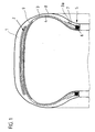
- the layers of the belt 2 are made of steel cord reinforcements embedded in a rubber compound which are parallel to each other within each layer, the steel cords of one layer being oriented in crossing relationship with the steel cords of the further layer and with the tire circumferential direction respectively include an angle between 15 ° and 30 °.
- the carcass 3 can also be designed in a conventional and known manner and thus have reinforcing threads of a textile material or steel cord embedded in a rubber compound and extending in the radial direction.
- the carcass 3 is guided around the bead cores 6 from the inside to the outside, their elevations 3a extend in the direction of the belt 2 next to the bead core profiles 7.
- the insert 9 prevents injuries to the inner layer by penetrating from the outside into the tire, pointed objects.
- the insert 9 has been positioned on the inner layer 4 during the construction of the tire and is therefore located between it and the carcass 3.
- the insert 9 is arranged in an annular manner circumferentially closed at least below the profile and shoulder region.
- the insert 9 has on its upper side facing the carcass 3 10, a coating of Teflon, which prevents the chemical adhesion between the top of the insert 10 and the carcass 3.
- the bottom 11 of the insert is firmly connected to the inner layer 4.
- the thickness of the insert 9 is the same over the entire insert and is here 0.4 mm.
- FIG. 2a-c in a representation isolated from the other tire components, the insert 9 is shown prior to penetration and in the case of a penetrating pointed object 12.
- the arrow symbolizes the penetrating object 12.
- the top side 10 of the insert has a non-stick coating, so that the top side 10 of the insert does not adhere to the resting carcass ply, not shown.
- the insert 9 is made of a highly flexible, stretchable and not piercing polymer, so that the insert is funnel-shaped deflected axially inward by the penetrating object. This is only possible because the top 10 does not adhere to the carcass ply while the carcass does not change shape. Due to the deflection and dodging the penetration of the article whose energy is absorbed by the insert 9.
- FIG. 2 c shows a representation of the article 12 which has penetrated deeper.
- FIG. 3 shows a three-dimensional view of the structure of a specific embodiment of the insert 9.
- the insert 9 is constructed in multiple layers from a plurality of layer sections 14 arranged horizontally and parallel to one another.
- the ply sections 14 are arranged in a matrix 15 of flexible, high tensile rubber.
- the ply sections 14 are flat and made of rigid material.
- the sections which are perforated in sections are offset horizontally relative to one another in such a way that a ply opening lies below or above a rigid ply section of an adjacent, parallel ply.
- the rubber matrix 15 consists of a highly flexible, in all directions equally stretchable mixture. In the case of an object 12 penetrating from the outside into the tire, which strikes the insert 9, the object strikes a rigid layer section 14.
- the energy of the penetrating article 12 is translated into elongation of the flexible rubber matrix by an approximately funnel-shaped Deformation in the direction of axially takes place inside.
- the insert 9 and so also the inner layer 4 is not broken.
- FIGS. 4 and 5 show further arrangements of the layer sections 14 on the basis of the embodiment of the insert described in FIG.
- the ply sections of Figure 4 are layers 13 of rigid material.
- the rubber matrix 15 is made of highly flexible, stretchable rubber material.
- the surface 10 of the insert does not chemically adhere to the layer arranged above the surface.
- FIG. 5 shows a roof-tile-like arrangement of the layer sections 14, wherein each layer section is completely embedded in the rubber matrix 15.
- the insert 9 shown in cross section in FIG. 3 is supplemented by further layers in the form of highly elastic textile fabrics 16 such as nylon 6.
- FIG. 7 and FIG. 8 show a further embodiment of the insert 9, wherein FIG. 7 shows a cross-section and FIG. 8 shows a view of the insert 9 freed from the rubber matrix.
- the insert 9 has a layer-like structure of above-described, but here circular flat rigid layer sections 14, between which layers of highly elastic textile fabric 16 are located.
- the layer sections 14, which are circular in plan view, are arranged offset from one another horizontally per layer, so that the layer sections of a layer lying parallel cover the openings in the above and / or below layer.
- the upper side 10 does not chemically adhere to the carcass resting on this insert (not shown).
- the underside 11 is made here of material of the air-impermeable inner layer. In the design of the underside 11 of material of the inner layer, in all disclosed embodiments, this insert can be arranged directly on the inner layer, so that the inner layer can be applied with liner in one operation in the tire structure as a layer on the tire building drum.
Landscapes
- Engineering & Computer Science (AREA)
- Mechanical Engineering (AREA)
- Tires In General (AREA)
Abstract
Description
- Die Erfindung betrifft einen Fahrzeugluftreifen, bestehend aus einem profilierten Laufstreifen, einem mehrlagigen Gürtelverband, einer luftdichten Innenschicht, einer zumindest einlagig ausgeführten Karkasse, zugfesten Kernen, Seitenwänden und einer schützenden Einlage zur Vermeidung von Luftdruckverlust durch Undichtigkeit der Innenschicht durch einen von außen in den Reifen eindringenden Gegenstand, wobei die Einlage unterhalb des profilierten Laufstreifens über den Umfang geschlossen angeordnet ist und zumindest die Breite der Reifenaufstandsfläche aufweist.
- Pannensichere Fahrzeugluftreifen sind hinlänglich bekannt. Es gibt zwei unterschiedliche Lösungsansätze, um einen Fahrzeugluftreifen pannensicher zu gestalten. Der erste Lösungsansatz setzt im Pannenfall bei Druckluftverlust auf Notlaufeigenschaften durch beispielsweise verstärkte, selbstragende Seitenwandkonstruktionen.
- Der weitere Lösungsansatz, so wie der der vorliegenden Erfindung, soll einen Druckluftverlust und somit den Pannenfall von vornherein verhindern. Hier ist es beispielsweise aus der
EP 1 378 297 B1 bekannt, eine selbstdichtende Einlage an der axial innen gelegenen Seite der Innenschicht eines bereits vulkanisierten Reifens anzuordnen. Die selbstdichtende Einlage weist eine schwammartige Lage auf, die flüssiges Dichtungsmittel enthält. Ein Einstichkanal eines bis zur selbstdichtenden Lage eingedrungenen Gegenstandes wird durch das in dieser Lage enthaltene Dichtmittel verfüllt. Nachteilig ist, dass die Einlage in einem weiteren, an den Reifenaufbau und Vulkanisation anschließenden Arbeitsschritt am Reifen angeordnet werden muss. Dieses ist zeit- und kostenaufwendig. Die Einlage selbst ist in ihrer Herstellung teuer. Weiterhin kann das Dichtmittel einer solchen selbstdichtenden Lage nur Undichtigkeiten bis zu einem bestimmten Durchmesser abdichten. Bei größeren Gegenständen funktioniert die Dichtung nicht mehr zuverlässig. Bei tief in den Reifen eindringenden Gegenständen wird die luftdicht ausgeführte Innenschicht in jedem Fall verletzt, was zu einer Schwachstelle im Reifen trotz Selbstdichtung führt. Zudem können die Fahreigenschaften verändert werden. - Es ist die Aufgabe der Erfindung, einen pannenresistenten Reifen mit einer Einlage zu schaffen, die innerhalb des üblichen Reifenaufbauprozesses -vor der Vulkanisation- in den Reifen einzubringen ist. Ein Reifen mit dieser Einlage soll kostengünstig und einfach herstellbar sein und soll weiterhin einen Durchstich der luftdicht ausgeführten Innenschicht des Reifens durch einen von außen in den Reifen eindringenden Gegenstand verhindern. Weiterhin soll die Anordnung dieser Einlage die Fahreigenschaft des Reifens gegenüber Reifen ohne Einlage nicht verändern.
- Die Aufgabe wird gelöst, indem die Einlage zwischen Innenschicht und Karkasse zur Verhinderung von Durchstichen der Innenschicht angeordnet ist, dass zumindest die radial außen gelegene Oberfläche der Einlage aus einem Material oder einer Beschichtung besteht, welches nicht an der oberhalb der Einlage angeordneten Schicht haftet und dass die Einlage flexibel und zum Ausweichen bei eindringenden Gegenständen leicht verform- und dehnbar ausgeführt ist.
- Erfindungswesentlich ist, dass die zwischen Innenschicht und Karkasse angeordnete Einlage nicht an der oberhalb der Einlage angeordneten Schicht chemisch anhaftet, sondern bei einem von außen eindringenden Gegenstand in alle Raumrichtungen gleich dehnbar und flexibel reagiert. Wenn ein Gegenstand den erfindungsgemäßen Reifen von außen bis zur Einlage durchdringt, wird die hochflexible und dehnbare Einlage durch diesen Gegenstand nicht durchstochen, sondern in einem trichterförmigen Bereich um den eindringenden Gegenstand nach axial innen ausweichen. Die Einlage weist eine hohe Energieabsorptionsfähigkeit auf.
Die Einlage und somit die axial innen unterhalb der Einlage angeordnete Innenschicht wird nicht durchstochen, so dass der Reifen luftdicht erhalten bleibt. - Die Einlage wird während des üblichen Reifenaufbauprozesses eines Fahrzeugluftreifens als ein Reifenbauteil mit um die zylindrische Reifenaufbautrommel oberhalb der luftdicht geführten Innenschicht herumgelegt und nach Beendigung des Reifenaufbaus vulkanisiert.
- Die unerwünschte chemische Haftung mit einer oberhalb der Einlage aufliegenden Schicht, zumeist der Karkasslage, kann dadurch zuverlässig und dauerhaft vermieden werden, dass zumindest die radial außen gelegene Oberfläche der Einlage aus Teflon besteht oder eine Beschichtung aus Teflon aufweist. Durch diese Beschichtung ist eine chemische Haftung mit der oberhalb der Einlage aufliegenden Schicht verhindert.
- Die Einlage muss zwei Eigenschaften aufweisen, einerseits muss sie flexibel und dehnbar sein, andererseits darf sie nicht von dem eindringenden Gegenstand durchstochen werden dürfen. Daher ist es vorteilhaft, wenn die Einlage eine Polymerlage oder eine in Gummi eingebettete Lage oder eine in Gummi eingebettete Cordlage aus Nylon 6, Nylon 6.6, Elastan, Polyamid, Aramid oder Leichtmetall ist.
- In einer besonderen Ausführungsform, bei der parallel zur ersten Innenschicht zwischen dieser ersten Innenschicht und der Karkasse eine zweite Innenschicht angeordnet ist, sind die erste und die zweite Innenschicht derart zueinander angeordnet sind, dass beide die durchstichresistente Einlage zwischen sich einschließen. Im Sonderfall der geschlossenen Enden beider Innenschichten kann oberhalb der durchstichresistenten Einlage eine nicht haftende Latexlage eingebracht sein. Es ist eine höhere Stabilität der Einlage erreicht. Durch den Einschluss der Einlage zwischen zwei Innenschichten ist sie innerhalb des Reifens fest nach Art eines Verbundes, aber ohne chemische Haftung zur oberhalb gelegenen Schicht, angeordnet.
- Der erfindungsgemäße Reifen ist ebenfalls bei seitlich durch die Seitenwände eindringenden Gegenständen pannenresistent, wenn die durchstichresistente Einlage bis in die Seitenwände reichend ausgeführt ist. Die durchstichresistente Einlage kann sich bis zum Wulstbereich erstrecken.
- Vorteilhaft ist es, wenn die durchstichresistente Einlage mehrlagig ausgeführt ist.
- In einer Ausführungsform besteht die Einlage aus einer Gummimatrix, in die wenigstens zwei voneinander beabstandete Lagen eingebettet sind, die parallel zur Einlagenoberfläche angeordnet sind und aus rigiden Material bestehen. "Rigide" meint hier eine Materialbeschaffenheit, die starr, steif, fest und unnachgiebig ist, wodurch Durchstiche durch spitze Gegenstände wirksam vermieden werden.
- In einer Abwandlung der vorbeschriebenen Ausführungsform des Reifens ist jede Lage der Einlage in regelmäßigen Abständen durchbrochen, wobei die zweite Lage (oder jede weitere Lage) derart gegenüber der ersten (benachbarten) Lage versetzt angeordnet ist, so dass die Durchbrechungen einer Lage unter- oder oberhalb von rigiden Lagenabschnitten der benachbarten weiteren Lage liegen.
- Die Gummimatrix der Einlage ist aus einer Gummimischung, die nach der Reifenvulkanisation hochflexibel und dehnbar ist. Die in der Einlage eingebetteten Lagen und Lagenabschnitte bestehen aus rigidem Material. Es handelt sich bei allen Ausführungen um dünne Lagen oder Filme beispielsweise aus Polyester, Polyamid und/oder Metalle oder Metalllegierungen, vorzugsweise Leichtmetalle. Die Lagenabschnitte weisen vorteilhafterweise eine Breite von 5mm und eine Länge von 300 mm, vorzugsweise eine Breite von 20 mm und eine Länge von 150 mm auf. Die Lagenabschnitte können aber auch sämtlich oder teilweise Kreise und/oder Ovale mit einem Durchmesser von 5 mm bis 50 mm, vorzugsweise 10 mm sein. Die Breite einer Lage ist von der Dimension des Reifens abhängig und beträgt bei einem PKW-Reifen von 100 mm bis 500 mm.
- Bei einem von außen eindringenden Gegenstand, der auf die Einlage stößt, wirken die in die Einlage eingebetteten Lagen bzw. Lagenabschnitte aus rigidem Material als "Protektoren, Schutzschilde", durch die der Gegenstand nicht durchstoßen kann. Die Energie des eindringenden Gegenstandes wird in Dehnung der flexiblen, die Lagen, - abschnitte fest umschließenden Gummimatrix umgesetzt. Beim Einsatz von Lagenabschnitten innerhalb der Einlage weist die Einlage eine höhere Flexibilität und Verformbarkeit durch Bewegbarkeit der einzelnen Lagenabschnitte untereinander auf.
- Diese Verformbarkeit der Einlage wird weiter erhöht, wenn wenigstens eine weitere Lage in Form eines Textilgewebes zwischen den Lagen aus rigidem Material angeordnet ist, wobei das Textilgewebe aus hochdehnbarem Material wie beispielsweise Nylon 6, Nylon 6.6 und/oder Elastan besteht.
- Bei einer weiteren Ausführungsform der im Reifen angeordneten Einlage, sind die eingebetteten Lagen parallel zueinander in einer Gummimasse derart eingebettet, dass sie dachziegelartig einander überlappend und gegeneinander verschiebbar sind. Hierdurch ist eine optimale Abdeckung der Einlage durch rigide dachziegelartig sich überlappende Lagenabschnitte erreicht, wobei dennoch eine hohe Flexibilität der gesamten Einlage erhalten bleibt.
- Diese weitere Ausführungsform kann flexibler und dehnbarer gestaltet sein, wenn wenigstens eine weitere Lage in Form eines hochdehnbaren Textilgewebes oberhalb und/oder unterhalb der dachziegelartig einander überlappenden Lagen parallel zur Oberfläche der Einlage angeordnet ist.
- Weitere Merkmale, Vorteile und Einzelheiten der Erfindung werden anhand der Zeichnungen, dies schematische Ausführungsbeispiele darstellen, näher erläutert. Es zeigen die:
- Fig.1
- einen Querschnitt eines erfindungsgemäßen Reifens mit einer pannenresistenten Einlage
- Fig.2a
- eine isolierte dreidimensionale Darstellung der Einlage vor Eindringen eines spitzen Gegenstandes
- Fig.2b
- eine Darstellung der Einlage der Fig.2a bei Eindringen des Gegenstandes
- Fig.2c
- eine Darstellung der Einlage der Fig.2a bei Eindringen des Gegenstandes
- Fig.3
- eine dreidimensionale Darstellung einer Ausführungsform der Einlage
- Fig.4
- eine dreidimensionale Darstellung einer anderen Ausführungsform der Einlage
- Fig.5
- eine dreidimensionale Darstellung einer weiteren Ausführungsform der Einlage
- Fig.6
- einen Querschnitt einer weitere Ausführungsform der Einlage
- Fig.7
- einen Querschnitt durch eine andere Ausführungsform der Einlage
- Fig.8
- eine abgedeckte Aufsicht auf die Lagen der Einlage der Fig.7.
- Die Fig.1 zeigt die wesentlichen Bestandteile, aus welchen sich der erfindungsgemäße Reifen zusammensetzt. Dieses sind ein profilierter Laufstreifen 1, ein bei der gezeigten Ausführung aus zwei Lagen und einer Bandage bestehender Gürtelverband 2, eine Karkasse 3, eine luftdicht ausgeführte Innenschicht 4, Wülste 5 mit Wulstkernen 6 und Wulstkernprofilen 7, sowie Seitenwände 8 und zwischen Innenschicht 4 und Karkasse 3 angeordnete Einlage 9. Die Lagen des Gürtels 2 bestehen aus in eine Gummimischung eingebetteten Festigkeitsträgern aus Stahlcord, welche innerhalb jeder Lage parallel zueinander verlaufen, wobei die Stahlcorde der einen Lage in kreuzender Anordnung zu den Stahlcorden der weiteren Lage orientiert sind und mit der Reifenumfangsrichtung jeweils einen Winkel zwischen 15° und 30° einschließen. Auch die Karkasse 3 kann in herkömmlicher und bekannter Weise ausgeführt sein und somit in eine Gummimischung eingebettete, in radialer Richtung verlaufende Verstärkungsfäden aus einem textilen Material oder aus Stahlcord aufweisen. Die Karkasse 3 ist um die Wulstkerne 6 von innen nach außen geführt, ihre Hochschläge 3a verlaufen neben den Wulstkernprofilen 7 in Richtung Gürtel 2.
- Die Einlage 9 verhindert Verletzungen der Innenschicht durch von außen in den Reifen eindringenden, spitzen Gegenständen. Die Einlage 9 ist während des Aufbaus des Reifens auf der Innenschicht 4 positioniert worden und befindet sich daher zwischen dieser und der Karkassse 3. Die Einlage 9 ist ringförmig über den Umfang geschlossen zumindest unterhalb des Profil- und Schulterbereichs angeordnet. Die Einlage 9 weist an ihrer zur Karkasse 3 weisenden Oberseite 10 eine Beschichtung aus Teflon auf, die die chemische Haftung zwischen Oberseite der Einlage 10 und der Karkasse 3 verhindert. Die Unterseite 11 der Einlage ist fest mit der Innenschicht 4 verbunden. Die Dicke der Einlage 9 ist über die gesamte Einlage gleich und beträgt hier 0,4 mm.
- In der Fig.2a-c ist in einer von den übrigen Reifenbauteilen isolierten Darstellung die Einlage 9 vor dem Eindringen und im Fall eines eindringenden spitzen Gegenstandes 12 dargestellt. Der Pfeil symbolisiert den eindringenden Gegenstand 12. Die Oberseite 10 der Einlage weist eine Antihaftbeschichtung auf, so dass die Oberseite 10 der Einlage nicht an der nicht dargestellten aufliegenden Karkasslage anhaftet. Die Einlage 9 ist aus einem hochflexiblen, dehnbaren und nicht zu durchstechenden Polymer gefertigt, so dass durch den eindringenden Gegenstand die Einlage trichterförmig nach axial innen ausgelenkt wird. Dieses ist nur ermöglicht, weil die Oberseite 10 nicht an der Karkasslage anhaftet, während die Karkasse ihre Form nicht verändert. Durch die Auslenkung und das Ausweichen beim Eindringen des Gegenstandes wird dessen Energie durch die Einlage 9 absorbiert. Die trichterförmige Auslenkung im Zeitpunkt des Eindringens ist größer als der eingedrungene Gegenstand 12. Die Einlage 9 wird nicht durchstochen. Die unter der Einlage angeordnete, nicht dargestellte Innenschicht 4 bleibt unverletzt. Die Fig.2c zeigt eine Darstellung des tiefer eingedrungenen Gegenstandes 12.
- Die Fig.3 zeigt eine räumliche Darstellung des Aufbaus einer bestimmten Ausführungsform der Einlage 9. Die Einlage 9 ist mehrlagig aus mehreren horizontal und parallel zueinander angeordneten Lagenabschnitten 14 aufgebaut. Die Lagenabschnitte 14 sind in einer Matrix 15 aus flexiblem, hochdehnbarem Gummi angeordnet. Die Lagenabschnitte 14 sind flach und bestehen aus rigidem Material. Die in Abschnitte durchbrochenen Lagen sind zueinander derart horizontal versetzt, dass eine Lagendurchbrechung unter- oder oberhalb eines rigiden Lagenabschnittes einer benachbarten, parallelen Lagen liegt. Die Gummimatrix 15 besteht aus einer hochflexiblen, in alle Raumrichtungen gleich dehnbaren Mischung. Bei einem von außen in den Reifen eindringenden Gegenstand 12, der auf die Einlage 9 stößt, trifft der Gegenstand auf einen rigiden Lagenabschnitt 14. Dieser wirkt quasi als steifes Schutzschild. Die Energie des eindringenden Gegenstandes 12 wird in Dehnung der flexiblen Gummimatrix umgesetzt, indem eine in etwa trichterförmige Verformung in Richtung axial innen stattfindet. Die Einlage 9 und so auch die Innenschicht 4 wird nicht durchbrochen.
- Die Fig.4 und Fig.5 zeigen weitere Anordnungen der Lagenabschnitte 14 auf Basis der in Fig.3 beschriebenen Ausgestaltung der Einlage. Die Lagenabschnitte der Fig.4 sind Lagen 13 aus rigidem Material. Die Gummimatrix 15 besteht aus hochflexiblem, dehnbaren Gummimaterial. Die Oberfläche 10 der Einlage haftet chemisch nicht an der oberhalb der Oberfläche angeordneten Lage. Die Fig.5 zeigt eine dachziegelartige Anordnung der Lagenabschnitte 14, wobei jeder Lagenabschnitt vollständig in der Gummimatrix 15 eingebettet ist.
- In der Fig.6 ist die in der Fig.3 im Querschnitt dargestellte Einlage 9 um weitere Lagen in Form von hochdehnbaren textilen Geweben 16 wie Nylon 6 ergänzt.
- In der Fig.7 und Fig.8 ist eine weitere Ausführungsform der Einlage 9 dargestellt, wobei die Fig.7 einen Querschnitt und die Fig.8 eine von der Gummimatrix befreite Aufsicht auf die Einlage 9 darstellt.
Die Einlage 9 weist einen lagenartigen Aufbau aus vorbeschriebenen, hier aber kreisförmigen flachen rigiden Lagenabschnitten 14 auf, zwischen denen sich Lagen aus hochdehnbarem textilem Gewebe 16 befinden. Die in Aufsicht kreisförmigen Lagenabschnitte 14 sind pro Lage zueinander horizontal versetzt angeordnet, so dass die Lagenabschnitte einer parallel liegenden Lage die Durchbrechungen der darüber und/oder darunterliegenden Lage abdecken. Die Oberseite 10 haftet chemisch nicht an der oberhalb auf dieser Einlage aufliegenden Karkasse (nicht dargestellt). Die Unterseite 11 ist hier aus Material der luftundurchlässigen Innenschicht gefertigt. Bei Gestaltung der Unterseite 11 aus Material der Innenschicht kann bei allen offenbarten Ausführungsformen diese Einlage unmittelbar auf der Innenschicht angeordnet sein, so dass die Innenschicht mit Einlage in einem Arbeitsgang beim Reifenaufbau als eine Lage auf die Reifenaufbautrommel aufgebracht werden kann. -
- 1
- Laufstreifen
- 2
- Gürtel
- 3
- Karkasse
- 4
- Innenschicht
- 5
- Wulst
- 6
- Wulstkern
- 7
- Wulstkernprofil
- 8
- Seitenwand
- 9
- Einlage
- 10
- Oberseite der Einlage
- 11
- Unterseite der Einlage
- 12
- Gegenstand
- 13
- Lage
- 14
- Lagenabschnitt
- 15
- Gummimatrix
- 16
- Gewebe
Claims (13)
- Fahrzeugluftreifen, bestehend aus einem profilierten Laufstreifen (1), einem mehrlagigen Gürtelverband (2), einer luftdichten Innenschicht (4), einer zumindest einlagig ausgeführten Karkasse (3), zugfesten Kernen (6), Seitenwänden (8) und einer schützenden Einlage (9) zur Vermeidung von Luftdruckverlust durch Undichtigkeit der Innenschicht (4) durch einen von außen in den Reifen eindringenden Gegenstand (12), wobei die Einlage (9) unterhalb des profilierten Laufstreifens (1) über den Umfang geschlossen angeordnet ist und zumindest die Breite der Reifenaufstandsfläche aufweist,
dadurch gekennzeichnet,
dass die Einlage (9) zwischen Innenschicht (4) und Karkasse (3) zur Verhinderung von Durchstichen der Innenschicht (4) angeordnet ist,
dass zumindest die radial außen gelegene Oberfläche (10) der Einlage aus einem Material oder einer Beschichtung besteht, welches nicht an der oberhalb der Einlage (9) angeordneten Schicht haftet und
dass die Einlage (9) flexibel und zum Ausweichen bei eindringenden Gegenständen leicht verform- und dehnbar ausgeführt ist. - Fahrzeugluftreifen nach Anspruch 1,
dadurch gekennzeichnet,
dass zumindest die radial außen gelegene Oberfläche (10) der Einlage aus Teflon besteht oder eine Beschichtung aus Teflon aufweist. - Fahrzeugluftreifen nach Anspruch 1 oder 2,
dadurch gekennzeichnet,
dass die Einlage (9) eine Polymerlage oder eine in Gummi eingebettete Lage oder eine in Gummi eingebettete Cordlage aus Nylon 6, Nylon 6.6, Elastan, Polyamid, Aramid oder Leichtmetall ist. - Fahrzeugluftreifen nach einem der vorangehenden Ansprüche,
dadurch gekennzeichnet,
dass parallel zur ersten Innenschicht (4) zwischen dieser ersten Innenschicht (4) und der Karkasse (3) eine zweite Innenschicht angeordnet ist, wobei die erste (4) und die zweite Innenschicht derart zueinander angeordnet sind, dass beide die durchstichresistente Einlage (9) zwischen sich einschließen. - Fahrzeugluftreifen nach einem der vorangehenden Ansprüche,
dadurch gekennzeichnet,
dass oberhalb der durchstichresistenten Einlage (9) eine nicht haftende Latexlage eingebracht ist. - Fahrzeugluftreifen nach einem der vorangehenden Ansprüche,
dadurch gekennzeichnet,
dass die durchstichresistente Einlage (9) bis in die Seitenwände (8) reichend ausgeführt ist. - Fahrzeugluftreifen nach einem der Ansprüche,
dadurch gekennzeichnet,
dass die durchstichresistente Einlage (9) mehrlagig ausgeführt ist. - Fahrzeugluftreifen nach Anspruch 7,
dadurch gekennzeichnet,
dass die Einlage (9) aus einer Gummimatrix (15) besteht, in die wenigstens zwei voneinander beabstandete Lagen (13) eingebettet sind, die parallel zur Einlagenoberfläche (10) angeordnet sind und aus rigiden Material bestehen. - Fahrzeugluftreifen nach Anspruch 8,
dadurch gekennzeichnet,
dass jede Lage (13) in regelmäßigen Abständen durchbrochen ist und die zweite Lage derart gegenüber der ersten Lage versetzt angeordnet ist, so dass die Durchbrechungen einer Lage unter- oder oberhalb von rigiden Lagenabschnitten (14) der weiteren Lage liegen. - Fahrzeugluftreifen nach Anspruch 8,9,
dadurch gekennzeichnet,
dass die Lagenabschnitte (14) eine Breite von 5 mm und eine Länge von 300 mm, vorzugsweise eine Breite von 20 mm und eine Länge von 150 mm aufweisen oder dass die Lagenabschnitte Kreise oder Ovale mit einem Durchmesser von 5 mm bis 50 mm, vorzugsweise 10 mm sind. - Fahrzeugluftreifen nach Anspruch 8 - 10,
dadurch gekennzeichnet,
dass wenigstens eine weitere Lage in Form eines Textilgewebes (16) zwischen den Lagen (13, 14) aus rigidem Material angeordnet ist, wobei das Textilgewebe (16) aus hochdehnbarem Material wie beispielsweise Nylon 6, Nylon 6.6 und/oder Elasten besteht. - Fahrzeugreifen nach Anspruch 7,
dadurch gekennzeichnet,
dass die Einlage (9) aus parallel zueinander angeordneten, in einer Gummimasse (15) eingebetteten Lagen (13) besteht, die dachziegelartig einander überlappend und gegeneinander verschiebbar angeordnet sind. - Fahrzeugreifen nach Anspruch 12,
dadurch gekennzeichnet,
dass wenigstens eine weitere Lage (16) in Form eines hochdehnbaren Textilgewebes oberhalb und/oder unterhalb der dachziegelartig einander überlappenden Lagen (14) parallel zur Oberfläche (10) der Einlage (9) angeordnet ist.
Applications Claiming Priority (1)
| Application Number | Priority Date | Filing Date | Title |
|---|---|---|---|
| DE102006016690A DE102006016690A1 (de) | 2006-04-08 | 2006-04-08 | Fahrzeugluftreifen mit einer pannenverhindernden Einlage |
Publications (2)
| Publication Number | Publication Date |
|---|---|
| EP1842698A1 true EP1842698A1 (de) | 2007-10-10 |
| EP1842698B1 EP1842698B1 (de) | 2009-01-21 |
Family
ID=38267616
Family Applications (1)
| Application Number | Title | Priority Date | Filing Date |
|---|---|---|---|
| EP07102675A Not-in-force EP1842698B1 (de) | 2006-04-08 | 2007-02-20 | Fahrzeugluftreifen mit einer pannenverhindernden Einlage |
Country Status (3)
| Country | Link |
|---|---|
| EP (1) | EP1842698B1 (de) |
| AT (1) | ATE421436T1 (de) |
| DE (2) | DE102006016690A1 (de) |
Cited By (1)
| Publication number | Priority date | Publication date | Assignee | Title |
|---|---|---|---|---|
| US20240336094A1 (en) * | 2023-04-10 | 2024-10-10 | The Goodyear Tire & Rubber Company | Puncture resistant tires |
Citations (7)
| Publication number | Priority date | Publication date | Assignee | Title |
|---|---|---|---|---|
| JPS5744504A (en) * | 1980-08-29 | 1982-03-13 | Bridgestone Corp | Pneumatic tire with built-in puncture preventive tube protector |
| EP0135463A1 (de) | 1983-08-15 | 1985-03-27 | The Goodyear Tire & Rubber Company | Selbstdichtender Luftreifen und Verfahren zu seiner Herstellung |
| GB2240953A (en) * | 1990-01-22 | 1991-08-21 | Ki Won Song | Tire protector |
| EP1099573A1 (de) * | 1999-02-01 | 2001-05-16 | Sumitomo Rubber Industries, Ltd. | Luftreifen und verfahren zur herstellung des luftreifens |
| EP1174290A1 (de) | 2000-01-27 | 2002-01-23 | Honda Giken Kogyo Kabushiki Kaisha | Schlauchloser reifen |
| EP1378397B1 (de) | 2002-07-05 | 2004-11-24 | DaimlerChrysler AG | Vorrichtung und Verfahren zur manuellen Höhenverstellung eines Ladebodens eines Kraftfahrzeuges |
| WO2005039894A1 (de) | 2003-10-24 | 2005-05-06 | Continental Aktiengesellschaft | Fahrradreifen mit verstärkungslage |
-
2006
- 2006-04-08 DE DE102006016690A patent/DE102006016690A1/de not_active Withdrawn
-
2007
- 2007-02-20 AT AT07102675T patent/ATE421436T1/de not_active IP Right Cessation
- 2007-02-20 EP EP07102675A patent/EP1842698B1/de not_active Not-in-force
- 2007-02-20 DE DE502007000392T patent/DE502007000392D1/de active Active
Patent Citations (7)
| Publication number | Priority date | Publication date | Assignee | Title |
|---|---|---|---|---|
| JPS5744504A (en) * | 1980-08-29 | 1982-03-13 | Bridgestone Corp | Pneumatic tire with built-in puncture preventive tube protector |
| EP0135463A1 (de) | 1983-08-15 | 1985-03-27 | The Goodyear Tire & Rubber Company | Selbstdichtender Luftreifen und Verfahren zu seiner Herstellung |
| GB2240953A (en) * | 1990-01-22 | 1991-08-21 | Ki Won Song | Tire protector |
| EP1099573A1 (de) * | 1999-02-01 | 2001-05-16 | Sumitomo Rubber Industries, Ltd. | Luftreifen und verfahren zur herstellung des luftreifens |
| EP1174290A1 (de) | 2000-01-27 | 2002-01-23 | Honda Giken Kogyo Kabushiki Kaisha | Schlauchloser reifen |
| EP1378397B1 (de) | 2002-07-05 | 2004-11-24 | DaimlerChrysler AG | Vorrichtung und Verfahren zur manuellen Höhenverstellung eines Ladebodens eines Kraftfahrzeuges |
| WO2005039894A1 (de) | 2003-10-24 | 2005-05-06 | Continental Aktiengesellschaft | Fahrradreifen mit verstärkungslage |
Cited By (1)
| Publication number | Priority date | Publication date | Assignee | Title |
|---|---|---|---|---|
| US20240336094A1 (en) * | 2023-04-10 | 2024-10-10 | The Goodyear Tire & Rubber Company | Puncture resistant tires |
Also Published As
| Publication number | Publication date |
|---|---|
| DE102006016690A1 (de) | 2007-10-11 |
| EP1842698B1 (de) | 2009-01-21 |
| ATE421436T1 (de) | 2009-02-15 |
| DE502007000392D1 (de) | 2009-03-12 |
Similar Documents
| Publication | Publication Date | Title |
|---|---|---|
| DE102010029455B4 (de) | Luftreifen | |
| DE69921210T2 (de) | Verbesserungen in Reifen | |
| EP2857226B1 (de) | Reifenanordnung für eine Fahrradfelge | |
| WO2023134821A1 (de) | Fahrzeugluftreifen | |
| DE102010038199A1 (de) | Fahrzeugluftreifen | |
| DE3102614A1 (de) | Radialreifen-karkasse und verfahren zu ihrer herstellung | |
| DE1001139B (de) | Schlauchloser Luftreifen | |
| EP3028873A1 (de) | Nutzfahrzeugreifen mit gürtel | |
| EP0264539B1 (de) | Gürtelreifen für Fahrzeuge | |
| EP1842698B1 (de) | Fahrzeugluftreifen mit einer pannenverhindernden Einlage | |
| DE102013100364B4 (de) | Luftreifen | |
| EP2978615B1 (de) | Fahrzeugluftreifen | |
| EP3912833B1 (de) | Fahrzeugluftreifen | |
| EP0025180A2 (de) | Pflaster für die Reparatur von Fahrzeugreifen | |
| DE893162C (de) | Schlauchloser Luftreifen, insbesondere fuer Kraftfahrzeuge | |
| DE102020201474B4 (de) | Fahrradreifen und Verfahren zum Herstellen eines Fahrradreifens | |
| DE102015211889A1 (de) | Fahrzeugluftreifen mit Notlaufeigenschaften | |
| EP3281809B1 (de) | Fahrzeugluftreifen mit selbstdichtenden eigenschaften | |
| DE102004059772B4 (de) | Fahrzeugluftreifen | |
| DE949870C (de) | Schlauchloser Luftreifen fuer Fahrzeuge | |
| DE102005050677A1 (de) | Fahrzeugluftreifen | |
| DE102016216732A1 (de) | Fahrzeugluftreifen mit Notlaufeigenschaften | |
| EP1535763B1 (de) | Verfahren zur Herstellung eines Fahrzeugluftreifens | |
| DE102022200363A1 (de) | Fahrzeugluftreifen | |
| DE102014222303A1 (de) | Fahrzeugluftreifen mit asymmetrischer Karkasse |
Legal Events
| Date | Code | Title | Description |
|---|---|---|---|
| PUAI | Public reference made under article 153(3) epc to a published international application that has entered the european phase |
Free format text: ORIGINAL CODE: 0009012 |
|
| AK | Designated contracting states |
Kind code of ref document: A1 Designated state(s): AT BE BG CH CY CZ DE DK EE ES FI FR GB GR HU IE IS IT LI LT LU LV MC NL PL PT RO SE SI SK TR |
|
| AX | Request for extension of the european patent |
Extension state: AL BA HR MK YU |
|
| 17P | Request for examination filed |
Effective date: 20080410 |
|
| AKX | Designation fees paid |
Designated state(s): AT BE BG CH CY CZ DE DK EE ES FI FR GB GR HU IE IS IT LI LT LU LV MC NL PL PT RO SE SI SK TR |
|
| 17Q | First examination report despatched |
Effective date: 20080530 |
|
| GRAP | Despatch of communication of intention to grant a patent |
Free format text: ORIGINAL CODE: EPIDOSNIGR1 |
|
| GRAS | Grant fee paid |
Free format text: ORIGINAL CODE: EPIDOSNIGR3 |
|
| GRAA | (expected) grant |
Free format text: ORIGINAL CODE: 0009210 |
|
| AK | Designated contracting states |
Kind code of ref document: B1 Designated state(s): AT BE BG CH CY CZ DE DK EE ES FI FR GB GR HU IE IS IT LI LT LU LV MC NL PL PT RO SE SI SK TR |
|
| REG | Reference to a national code |
Ref country code: GB Ref legal event code: FG4D Free format text: NOT ENGLISH |
|
| REG | Reference to a national code |
Ref country code: CH Ref legal event code: EP |
|
| REG | Reference to a national code |
Ref country code: IE Ref legal event code: FG4D Free format text: LANGUAGE OF EP DOCUMENT: GERMAN |
|
| REF | Corresponds to: |
Ref document number: 502007000392 Country of ref document: DE Date of ref document: 20090312 Kind code of ref document: P |
|
| PG25 | Lapsed in a contracting state [announced via postgrant information from national office to epo] |
Ref country code: NL Free format text: LAPSE BECAUSE OF FAILURE TO SUBMIT A TRANSLATION OF THE DESCRIPTION OR TO PAY THE FEE WITHIN THE PRESCRIBED TIME-LIMIT Effective date: 20090121 |
|
| NLV1 | Nl: lapsed or annulled due to failure to fulfill the requirements of art. 29p and 29m of the patents act | ||
| PG25 | Lapsed in a contracting state [announced via postgrant information from national office to epo] |
Ref country code: SI Free format text: LAPSE BECAUSE OF FAILURE TO SUBMIT A TRANSLATION OF THE DESCRIPTION OR TO PAY THE FEE WITHIN THE PRESCRIBED TIME-LIMIT Effective date: 20090121 Ref country code: FI Free format text: LAPSE BECAUSE OF FAILURE TO SUBMIT A TRANSLATION OF THE DESCRIPTION OR TO PAY THE FEE WITHIN THE PRESCRIBED TIME-LIMIT Effective date: 20090121 Ref country code: LT Free format text: LAPSE BECAUSE OF FAILURE TO SUBMIT A TRANSLATION OF THE DESCRIPTION OR TO PAY THE FEE WITHIN THE PRESCRIBED TIME-LIMIT Effective date: 20090121 Ref country code: ES Free format text: LAPSE BECAUSE OF FAILURE TO SUBMIT A TRANSLATION OF THE DESCRIPTION OR TO PAY THE FEE WITHIN THE PRESCRIBED TIME-LIMIT Effective date: 20090502 |
|
| REG | Reference to a national code |
Ref country code: IE Ref legal event code: FD4D |
|
| BERE | Be: lapsed |
Owner name: CONTINENTAL A.G. Effective date: 20090228 |
|
| PG25 | Lapsed in a contracting state [announced via postgrant information from national office to epo] |
Ref country code: PL Free format text: LAPSE BECAUSE OF FAILURE TO SUBMIT A TRANSLATION OF THE DESCRIPTION OR TO PAY THE FEE WITHIN THE PRESCRIBED TIME-LIMIT Effective date: 20090121 Ref country code: PT Free format text: LAPSE BECAUSE OF FAILURE TO SUBMIT A TRANSLATION OF THE DESCRIPTION OR TO PAY THE FEE WITHIN THE PRESCRIBED TIME-LIMIT Effective date: 20090622 Ref country code: LV Free format text: LAPSE BECAUSE OF FAILURE TO SUBMIT A TRANSLATION OF THE DESCRIPTION OR TO PAY THE FEE WITHIN THE PRESCRIBED TIME-LIMIT Effective date: 20090121 Ref country code: SE Free format text: LAPSE BECAUSE OF FAILURE TO SUBMIT A TRANSLATION OF THE DESCRIPTION OR TO PAY THE FEE WITHIN THE PRESCRIBED TIME-LIMIT Effective date: 20090421 Ref country code: IS Free format text: LAPSE BECAUSE OF FAILURE TO SUBMIT A TRANSLATION OF THE DESCRIPTION OR TO PAY THE FEE WITHIN THE PRESCRIBED TIME-LIMIT Effective date: 20090521 |
|
| PG25 | Lapsed in a contracting state [announced via postgrant information from national office to epo] |
Ref country code: MC Free format text: LAPSE BECAUSE OF NON-PAYMENT OF DUE FEES Effective date: 20090228 |
|
| PG25 | Lapsed in a contracting state [announced via postgrant information from national office to epo] |
Ref country code: DK Free format text: LAPSE BECAUSE OF FAILURE TO SUBMIT A TRANSLATION OF THE DESCRIPTION OR TO PAY THE FEE WITHIN THE PRESCRIBED TIME-LIMIT Effective date: 20090121 Ref country code: EE Free format text: LAPSE BECAUSE OF FAILURE TO SUBMIT A TRANSLATION OF THE DESCRIPTION OR TO PAY THE FEE WITHIN THE PRESCRIBED TIME-LIMIT Effective date: 20090121 Ref country code: IE Free format text: LAPSE BECAUSE OF FAILURE TO SUBMIT A TRANSLATION OF THE DESCRIPTION OR TO PAY THE FEE WITHIN THE PRESCRIBED TIME-LIMIT Effective date: 20090121 Ref country code: CZ Free format text: LAPSE BECAUSE OF FAILURE TO SUBMIT A TRANSLATION OF THE DESCRIPTION OR TO PAY THE FEE WITHIN THE PRESCRIBED TIME-LIMIT Effective date: 20090121 |
|
| PLBE | No opposition filed within time limit |
Free format text: ORIGINAL CODE: 0009261 |
|
| STAA | Information on the status of an ep patent application or granted ep patent |
Free format text: STATUS: NO OPPOSITION FILED WITHIN TIME LIMIT |
|
| PG25 | Lapsed in a contracting state [announced via postgrant information from national office to epo] |
Ref country code: SK Free format text: LAPSE BECAUSE OF FAILURE TO SUBMIT A TRANSLATION OF THE DESCRIPTION OR TO PAY THE FEE WITHIN THE PRESCRIBED TIME-LIMIT Effective date: 20090121 Ref country code: RO Free format text: LAPSE BECAUSE OF FAILURE TO SUBMIT A TRANSLATION OF THE DESCRIPTION OR TO PAY THE FEE WITHIN THE PRESCRIBED TIME-LIMIT Effective date: 20090121 |
|
| 26N | No opposition filed |
Effective date: 20091022 |
|
| PG25 | Lapsed in a contracting state [announced via postgrant information from national office to epo] |
Ref country code: BG Free format text: LAPSE BECAUSE OF FAILURE TO SUBMIT A TRANSLATION OF THE DESCRIPTION OR TO PAY THE FEE WITHIN THE PRESCRIBED TIME-LIMIT Effective date: 20090421 |
|
| PG25 | Lapsed in a contracting state [announced via postgrant information from national office to epo] |
Ref country code: BE Free format text: LAPSE BECAUSE OF NON-PAYMENT OF DUE FEES Effective date: 20090228 |
|
| PG25 | Lapsed in a contracting state [announced via postgrant information from national office to epo] |
Ref country code: AT Free format text: LAPSE BECAUSE OF NON-PAYMENT OF DUE FEES Effective date: 20090220 |
|
| PG25 | Lapsed in a contracting state [announced via postgrant information from national office to epo] |
Ref country code: GR Free format text: LAPSE BECAUSE OF FAILURE TO SUBMIT A TRANSLATION OF THE DESCRIPTION OR TO PAY THE FEE WITHIN THE PRESCRIBED TIME-LIMIT Effective date: 20090422 |
|
| PG25 | Lapsed in a contracting state [announced via postgrant information from national office to epo] |
Ref country code: IT Free format text: LAPSE BECAUSE OF FAILURE TO SUBMIT A TRANSLATION OF THE DESCRIPTION OR TO PAY THE FEE WITHIN THE PRESCRIBED TIME-LIMIT Effective date: 20090121 |
|
| PG25 | Lapsed in a contracting state [announced via postgrant information from national office to epo] |
Ref country code: LU Free format text: LAPSE BECAUSE OF NON-PAYMENT OF DUE FEES Effective date: 20090220 |
|
| PG25 | Lapsed in a contracting state [announced via postgrant information from national office to epo] |
Ref country code: HU Free format text: LAPSE BECAUSE OF FAILURE TO SUBMIT A TRANSLATION OF THE DESCRIPTION OR TO PAY THE FEE WITHIN THE PRESCRIBED TIME-LIMIT Effective date: 20090722 |
|
| PG25 | Lapsed in a contracting state [announced via postgrant information from national office to epo] |
Ref country code: TR Free format text: LAPSE BECAUSE OF FAILURE TO SUBMIT A TRANSLATION OF THE DESCRIPTION OR TO PAY THE FEE WITHIN THE PRESCRIBED TIME-LIMIT Effective date: 20090121 |
|
| PG25 | Lapsed in a contracting state [announced via postgrant information from national office to epo] |
Ref country code: CY Free format text: LAPSE BECAUSE OF FAILURE TO SUBMIT A TRANSLATION OF THE DESCRIPTION OR TO PAY THE FEE WITHIN THE PRESCRIBED TIME-LIMIT Effective date: 20090121 |
|
| REG | Reference to a national code |
Ref country code: CH Ref legal event code: PL |
|
| GBPC | Gb: european patent ceased through non-payment of renewal fee |
Effective date: 20110220 |
|
| PG25 | Lapsed in a contracting state [announced via postgrant information from national office to epo] |
Ref country code: CH Free format text: LAPSE BECAUSE OF NON-PAYMENT OF DUE FEES Effective date: 20110228 Ref country code: LI Free format text: LAPSE BECAUSE OF NON-PAYMENT OF DUE FEES Effective date: 20110228 |
|
| PG25 | Lapsed in a contracting state [announced via postgrant information from national office to epo] |
Ref country code: GB Free format text: LAPSE BECAUSE OF NON-PAYMENT OF DUE FEES Effective date: 20110220 |
|
| REG | Reference to a national code |
Ref country code: FR Ref legal event code: PLFP Year of fee payment: 10 |
|
| REG | Reference to a national code |
Ref country code: FR Ref legal event code: PLFP Year of fee payment: 11 |
|
| REG | Reference to a national code |
Ref country code: FR Ref legal event code: PLFP Year of fee payment: 12 |
|
| PGFP | Annual fee paid to national office [announced via postgrant information from national office to epo] |
Ref country code: FR Payment date: 20210224 Year of fee payment: 15 |
|
| PGFP | Annual fee paid to national office [announced via postgrant information from national office to epo] |
Ref country code: DE Payment date: 20210228 Year of fee payment: 15 |
|
| REG | Reference to a national code |
Ref country code: DE Ref legal event code: R119 Ref document number: 502007000392 Country of ref document: DE |
|
| PG25 | Lapsed in a contracting state [announced via postgrant information from national office to epo] |
Ref country code: FR Free format text: LAPSE BECAUSE OF NON-PAYMENT OF DUE FEES Effective date: 20220228 |
|
| PG25 | Lapsed in a contracting state [announced via postgrant information from national office to epo] |
Ref country code: DE Free format text: LAPSE BECAUSE OF NON-PAYMENT OF DUE FEES Effective date: 20220901 |