EP1842635A2 - Circular saw with anti-kickback device - Google Patents
Circular saw with anti-kickback device Download PDFInfo
- Publication number
- EP1842635A2 EP1842635A2 EP07109070A EP07109070A EP1842635A2 EP 1842635 A2 EP1842635 A2 EP 1842635A2 EP 07109070 A EP07109070 A EP 07109070A EP 07109070 A EP07109070 A EP 07109070A EP 1842635 A2 EP1842635 A2 EP 1842635A2
- Authority
- EP
- European Patent Office
- Prior art keywords
- saw
- guide rail
- channel
- cam
- rib
- Prior art date
- Legal status (The legal status is an assumption and is not a legal conclusion. Google has not performed a legal analysis and makes no representation as to the accuracy of the status listed.)
- Granted
Links
Images


Classifications
-
- B—PERFORMING OPERATIONS; TRANSPORTING
- B27—WORKING OR PRESERVING WOOD OR SIMILAR MATERIAL; NAILING OR STAPLING MACHINES IN GENERAL
- B27B—SAWS FOR WOOD OR SIMILAR MATERIAL; COMPONENTS OR ACCESSORIES THEREFOR
- B27B9/00—Portable power-driven circular saws for manual operation
- B27B9/04—Guiding equipment, e.g. for cutting panels
-
- B—PERFORMING OPERATIONS; TRANSPORTING
- B23—MACHINE TOOLS; METAL-WORKING NOT OTHERWISE PROVIDED FOR
- B23D—PLANING; SLOTTING; SHEARING; BROACHING; SAWING; FILING; SCRAPING; LIKE OPERATIONS FOR WORKING METAL BY REMOVING MATERIAL, NOT OTHERWISE PROVIDED FOR
- B23D45/00—Sawing machines or sawing devices with circular saw blades or with friction saw discs
- B23D45/02—Sawing machines or sawing devices with circular saw blades or with friction saw discs with a circular saw blade or the stock mounted on a carriage
- B23D45/021—Sawing machines or sawing devices with circular saw blades or with friction saw discs with a circular saw blade or the stock mounted on a carriage with the saw blade mounted on a carriage
-
- B—PERFORMING OPERATIONS; TRANSPORTING
- B23—MACHINE TOOLS; METAL-WORKING NOT OTHERWISE PROVIDED FOR
- B23D—PLANING; SLOTTING; SHEARING; BROACHING; SAWING; FILING; SCRAPING; LIKE OPERATIONS FOR WORKING METAL BY REMOVING MATERIAL, NOT OTHERWISE PROVIDED FOR
- B23D45/00—Sawing machines or sawing devices with circular saw blades or with friction saw discs
- B23D45/16—Hand-held sawing devices with circular saw blades
-
- B—PERFORMING OPERATIONS; TRANSPORTING
- B23—MACHINE TOOLS; METAL-WORKING NOT OTHERWISE PROVIDED FOR
- B23D—PLANING; SLOTTING; SHEARING; BROACHING; SAWING; FILING; SCRAPING; LIKE OPERATIONS FOR WORKING METAL BY REMOVING MATERIAL, NOT OTHERWISE PROVIDED FOR
- B23D47/00—Sawing machines or sawing devices working with circular saw blades, characterised only by constructional features of particular parts
- B23D47/02—Sawing machines or sawing devices working with circular saw blades, characterised only by constructional features of particular parts of frames; of guiding arrangements for work-table or saw-carrier
Definitions
- the present invention relates to anti-kickback devices suitable for use on a manually operated portable circular saw, or the like.
- the devices are particularly suited for use on a circular saw which has a plunge-cut action.
- Circular saws with a plunge-cut action are known.
- such saws comprise a motor and gearbox disposed in a housing which includes a handle and manually operated switch for activating the motor.
- the housing is pivotally attached to a base plate which includes a cowl for accommodating a saw blade which is attached to the motor's or gearbox's output spindle.
- Springs are arranged to urge the housing into a position where the saw blade is wholly accommodated within the cowl.
- a user places the base plate on a work-piece, depresses the switch to activate the motor thereby initiating the saw blade's rotation and then plunges the housing towards the work-piece and base plate such that the rotating saw blade passes through an aperture in the base plate and into the work-piece.
- Kickback can occur as the saw is plunged into the work-piece.
- the kickback phenomenon is not wholly understood, but it often occurs in the early stages of plunging the blade into the work-piece.
- kick-back can cause the saw to jump out of the work-piece and back towards the operator with sufficient force to hit the operator.
- Kick-back might also occur if the saw is twisted out of alignment with the cut during cutting so that the blade catches the edge of the slot cut by the blade. As kick-back occurs, it is thought that the blade "grabs" the work-piece in the slot being cut.
- the blade can stop rotating with respect to the work-piece and, as the motor continues to drive the blade, the saw is thrown off the work-piece and towards the user.
- the user is typically unable to react as kick-back occurs and has insufficient time to disengage power to the motor.
- kickback is potentially dangerous and could cause severe injury.
- a guide rail is being used to guide the cutting direction of the saw as kickback occurs, the saw can jump out of the work-piece and across rail whilst the blade is exposed from the cowl and still rotating thereby damaging the rail and/or saw blade.
- Guide rails are known and can be used to guide various power tools, such as circular saws, routers or jigsaws.
- the rail can be placed on a work-piece and the tool is then placed on the rail.
- Clamping devices are often used to secure the guide rail to the work-piece.
- a rail comprises a length of extruding aluminium having a rib which extends along the length of the rail parallel to an edge of the rail along which the power tool operates.
- the rib engages with a channel formed in the base plate or footplate of the saw.
- the saw can be placed on the rail such that the rib and channel cooperate with one another. The operator is then able to run the saw along the rail whilst it cuts the work-piece.
- a strip of material having a relatively high coefficient of fiction is disposed on the surface of the rail which engages the work-piece to maintain the guide rail in position during use of the power tool. This is particularly useful if clamping devices are not being used.
- the present invention provides a hand operated circular saw comprising; a base plate having a channel arranged to cooperate with a guide rail member, a motor housing comprising a gripping portion having a switch for manual operation of a motor, and a cowl disposed on the base plate and being arranged to accommodate at least a portion of a saw blade disposed on an output spindle coupled to the motor, said housing, saw blade and/or output spindle being moveable with respect to the base plate and/or the cowl between a first position and a second position to facilitate a plunge-cut action of the circular saw; characterised in that the base plate further comprises a mechanism arranged to cooperate with a portion of a guide rail such that, when the circular saw is disposed on a guide rail the mechanism offers relatively low friction between the saw and guide rail in one direction thereby allowing the saw to be manually moved with respect to the guide rail in a first direction, and the mechanism offers relatively high friction between the saw and guide rail in another direction thereby preventing free movement of the saw with respect to the guide
- the mechanism should be arranged to prevent movement of the saw towards the user. Thus, should kick-back occur, the saw is prevented from moving back along a guide rail towards the operator.
- a mechanism can be integral with the circular saw so that the user need only place the saw on the guide rail - there is no need for a separate stopping device to be adjusted and locked onto the guide rail. Furthermore, the mechanism does not hinder proper use of the saw on a guide rail.
- the anti-kickback mechanism comprises a slide member having a contact surface, said slide member being arranged on a slide surface such that the slide member can move between a top and bottom position on the slide surface, and the contact surface is arranged to face an opposite surface of a channel in the saw's base plate.
- the contact surface is used to jam the rib of a guide rail, gripping it between the walls of the base plate's channel and preventing further movement in the second direction.
- the slide member is urged into the top position by a spring.
- the slide member is urged into a position where the contact surface makes contact with the guide rail rib no matter whether the saw is moving in the first or second directions.
- only a very small movement in the second direction is required to cause jamming of the rib by the anti-kickback device.
- the distance between the contact surface and opposite surface is less than the width of the channel when the slide member is in the top position. Furthermore, the distance between the contact surface and opposite surface is preferably greater than the width of a guide rail's rib when the slide member is in the bottom position.
- embodiments of the present invention further comprise a manually operable button coupled to the mechanism, the button being moveable between an operative and inoperative position, such that, when the button is in the inoperative position, the mechanism offers relatively high friction between the saw and guide rail if the saw is moved in the second direction. Furthermore, the mechanism offers relatively low friction between the saw and guide rail in the first direction when the button is inoperative position.
- the button is fixedly coupled to the mechanism by a pin and the pin can pass through a slot disposed in the base plate.
- the slot is preferably linear in its longitudinal direction and is angled with respect to the channel within an angular range, and the angular range is from an angle parallel to the channel and 10 degrees with respect to the channel.
- a spring is arranged to urge the button into the inoperative position.
- the operator of the saw can override the anti-kickback device when the saw is disposed on a guide rail.
- the spring has a first moveable end adapted to be in contact with the slide member and second end held in position relative to the base plate by a clamp.
- the clamp can comprise a portion of the base plate adapted to receive one or more components of the mechanism, and a mechanism retaining plate. Either one, or both, of the portion of the base plate or retaining plate comprise a protrusion adapted to fix the second end of the spring in relation to the base plate.
- a coupling member is arranged between the spring and slide member.
- the coupling member is disposable on the first end of the spring and the first end is held in position relative to the coupling member by a cup or nipple.
- the slide member is a roller and the coupling member has a cup portion adapted to receive a portion of the roller.
- the coupling member can be adapted to prevent the spring from disengaging with the slide member.
- the mechanism can alternatively comprise one or more cams, preferably rotatably disposed on a saw's footplate.
- the cam is urged into a first position by a spring, and, when in the first position, a portion of the cam extends a distance into a channel of the footplate such that the shortest distance between a contact surface of the cam and the opposite surface of the channel is less than the width of the channel, or less than the width of a rib on a guide rail.
- the cam can be moveable between a first and second position, such that, in the first position a portion of the cam extends a distance into a channel of the footplate such that the shortest distance between a contact surface of the cam and the opposite surface of the channel is less than the width of the channel, and in the second position, the distance between a contact surface of the cam and the opposite surface of the channel is greater than the width of a rib on a guide rail.
- the cam arrangement requires fewer parts than the other embodiments, thereby potentially reducing costs and the occurrence of malfunctions.
- the saw can be prevented from moving in a backwards direction towards the user (opposite to arrow A) by a force exerted onto the saw as the blade engages the work-piece during plunging, for instance.
- a force exerted onto the saw causes the anti-kick device to grip the saw to the guide rail with sufficient friction that the saw is prevented from moving towards the user along the rail.
- the saw can be prevented from jumping off the guide rail by the anti-kickback device's gripping action onto the guide rail.
- the saw can be held on the guide rail when/if kickback occurs.
- the saw is held to the work-piece if clamping devices are used to secure the guide rail on the work-piece, via the indirect coupling of the saw to the guide rail, and the guide rail to the work-piece.
- a first embodiment 32 of an anti-kickback device 30 is shown schematically.
- the device 32 comprises a block 34 a portion of which extends into the channel 24 of the footplate 26 by a relatively small distance beyond the dashed line B in a first position.
- a surface 36 of the block is arranged to engage with a side face of the guide rail's rib when the saw is disposed on the guide rail.
- the block is urged into the first position by a spring 38. In the first position, the distance by which the block's surface 36 extends into the channel is sufficient for the surface to contact the rail's rib.
- FIG. 3 a plan view of the first embodiment is shown in schematic form.
- the position a guide rail rib would occupy when the saw is disposed on the rail is shown as a dotted line 22; this line 22 indicates the rib disposed in the footplate channel 24.
- the block 34 can move with respect to the footplate 27 in a direction generally parallel to arrow A, since the block slides along a surface 40 which is inclined with respect to the opposite wall 42 of the channel.
- the distance between the guide rail rib and the surface 36 of the block varies depending on the position of the block in the device 32.
- the block can act as a brake by jamming the rib 22 between the block's surface 36 and opposing surface 42 of the channel when the footplate moves relative to the rib in an opposite direction to that indicated by arrow A. Conversely, the block imparts a relatively low amount of friction on the rib when the rib moves in a direction parallel to arrow A with respect to the device 32.
- the spring 38 urges the block into a position such that the block 34 engages the rib when there is no relative movement of the rib and footplate.
- the slightest movement of the footplate in a direction opposite to arrow A causes the block to move in a direction generally parallel to A relative to the anti-kickback device 32, thereby reducing the distance between the opposing surface of the block and channel, 36 and 42 respectively, and jamming the rib between the sliding surface 40, block and channel surface 42.
- relative movement of the footplate to the rib in a direction indicated by A is permitted because the block offers little friction between the footplate and rib.
- the spring constant of spring 40 should be chosen so that the force exerted on the block by the spring is relatively low.
- the optimum angle of inclination between the sliding surface 40 and opposite channel surface 42 is between 4 and 10 degrees and preferably 6.5 degrees. However, any angle between 2 and 15 degrees can be used.
- the block and spring are held in position in the anti-kickback device by a topplate, not shown in figure 3, which is arranged to be flush with the underside surface 27 of the footplate 26.
- roller is preferable to a sliding block arrangement as described for the first embodiment. It has been found that a roller is less likely to jam as the saw is moved down a guide rail in direction A: In some cases, the block can twist causing jamming between the block and the rib.
- a third embodiment is shown schematically in figure 6.
- This embodiment comprises one or more cam wheels 60, 62.
- the cam is held in position by a pin 64 and 66 respectively, about which each cam rotates.
- the cam has a contact surface 68 arranged to face an opposite surface of the channel such that a guide rail rib can fit between the contact surface of the cam and guide rail.
- the cam is rotatably moveable between a first and second position, such that in the first position, the distance between the contact surface of the cam and the opposite surface of the channel is less than the width of the guide rail's rib, and in the second position, the distance between the contact and opposite surface respectively is greater than the width of the channel in which the rib is locatable.
- a watch spring (not shown) can be used to urge the cams into a position where the cam engages with the guide rail's rib when the saw is disposed on the rail.
- the cam should be configured to operate with the same principles as those described above, that is to act a brake by jamming the rib in the channel to prevent relative movement of the rib in one direction, but to allow free movement of the rib in another opposite direction A.
- the smallest distance between the cam's contact surface 68 and the opposite surface of the channel 42 should be less than the width of the rib fitting into the channel (i.e. when the cam is in the first position, as discussed earlier).
- the anti-kickback device can be provided with a manually operable button 80, as shown in figure 7.
- the button is coupled to the roller 50 by a pin 82.
- the pin 82 is fixed to the roller so that it can not rotate with respect to the roller, although it is to be understood that non-fixed configuration could also be used.
- the pin is guided by a slot 84 passing through the footplate 26.
- the slot is linear in its longitudinal direction and has a width which is greater than the diameter of the pin to allow relatively free or unhindered movement of the pin therein.
- the slot can have parallel sides which are angled with respect to the guide rail rib or footplate channel within an angular range arranged to be between zero degrees (that is, parallel to the guide rail rib) and parallel to the sliding surface 40, with reference to figure 8.
- the button provides a means for the user to free or unlock the anti-kickback device should it become jammed during operation.
- the user is able to rotate the button to free the roller 50 from the guide rail rib 22 after a jamming event has occurred.
- rotation of the button causes the roller to rotate and free itself from the guide rail rib and sliding surfaces between which it has become jammed.
- the user can move the roller out of contact with the guide rail rib by pulling the button in a direction which moves the roller along or substantially along the sliding surface 40.
- the button By holding the button in this operative position, the roller is held away from the sliding surface and the anti-kickback device can be overridden.
- the user is thereby able to deactivate the anti-kickback device and move the circular saw along the guide rail in a direction opposite to arrow A (see figure 1, for instance) without the anti-kickback device locking the saw's footplate to the guide rail.
- This is an advantageous feature of the present invention because it allows the user to bring the saw back to a starting position on the guide rail after a cut has been completed without having to lift the saw from and then replace it on the guide rail at the start position.
- the coupling member has a generally cup-shaped profile adapted to receive the circumference 52 of the roller 50.
- the coupling member also comprises protrusions 94 which can form a cavity into which a first end of the spring is received.
- a nipple 96 can be provided to fit inside the coils of a spring and thereby hold the spring in relation to the coupling member, and hence the roller.
- a combination of both the protrusions 94 and nipple 96 are preferred, but either one of these arrangements could be used independently.
- a bar or rib-like protrusion 90 can be arranged on either or both of the footplate and/or a cover or retaining plate of the anti-kickback mechanism for retaining a second end of the spring in relation to the footplate.
- a bar-like protrusion 90 extends from a retaining plate 98 of the anti-kickback device 30.
- the retaining plate acts to retain the components of the anti-kickback device on the saw's footplate 26, amongst other functions.
- the rib is arranged to pinch the spring against a portion 93 of the footplate adapted to receive the anti-kickback device. In the case of a coil spring, the rib can be arranged to fit between neighbouring coils of the spring.
- the coupling member and/or the spring member retaining protrusion 90 act to help prevent the spring from disengaging with components of the anti-kickback device. This can assist with reducing the likelihood of the anti-kickback failing. Thus, the operator is able to utilise the device for long periods without having to service the anti-kickback device
- the block, roller or cam can be made from any suitable material, such as metal (steel or aluminium for instance), synthetic plastic (high impact nylon for instance), or resilient material (such as rubber). Factors, such as cost of manufacture, wear rates and coefficient of friction, may influence the choice of material.
- a separate anti-kickback device could be retro-fitted to a plunge-action circular saw's footplate by means of bolts engaging with threaded holes in the footplate, or the like.
- the anti-kickback device is disposed on the footplate and a series of anti-kickback devices could be disposed on a guide rail arranged to engage with the footplate channel of a circular saw.
- an anti-kickback device without a spring to urge the jamming device into a first position.
- the device could be arranged such that a spring is not necessary - the resilience of the material acts to urge the block into a suitable position.
- the spring is not limited to a coil spring as shown in the drawings, and other resilient means could be used, such as a leaf spring or a rod of resilient material (rubber, for instance).
Abstract
Description
- The present invention relates to anti-kickback devices suitable for use on a manually operated portable circular saw, or the like. The devices are particularly suited for use on a circular saw which has a plunge-cut action.
- Circular saws with a plunge-cut action are known. Typically, such saws comprise a motor and gearbox disposed in a housing which includes a handle and manually operated switch for activating the motor. The housing is pivotally attached to a base plate which includes a cowl for accommodating a saw blade which is attached to the motor's or gearbox's output spindle. Springs are arranged to urge the housing into a position where the saw blade is wholly accommodated within the cowl. During use, a user places the base plate on a work-piece, depresses the switch to activate the motor thereby initiating the saw blade's rotation and then plunges the housing towards the work-piece and base plate such that the rotating saw blade passes through an aperture in the base plate and into the work-piece. From this position, the saw can be moved in a forward direction along a cut-line thereby cutting a slot in the work-piece.
DE19635527 describes such a saw. Furthermore, FESTOOL GmbH sells such a saw under their product number TS55. - Kickback can occur as the saw is plunged into the work-piece. The kickback phenomenon is not wholly understood, but it often occurs in the early stages of plunging the blade into the work-piece. As the saw blade first engages with the work-piece kick-back can cause the saw to jump out of the work-piece and back towards the operator with sufficient force to hit the operator. Kick-back might also occur if the saw is twisted out of alignment with the cut during cutting so that the blade catches the edge of the slot cut by the blade. As kick-back occurs, it is thought that the blade "grabs" the work-piece in the slot being cut. In the worse case scenario, the blade can stop rotating with respect to the work-piece and, as the motor continues to drive the blade, the saw is thrown off the work-piece and towards the user. The user is typically unable to react as kick-back occurs and has insufficient time to disengage power to the motor.
- Thus, kickback is potentially dangerous and could cause severe injury. Furthermore, if a guide rail is being used to guide the cutting direction of the saw as kickback occurs, the saw can jump out of the work-piece and across rail whilst the blade is exposed from the cowl and still rotating thereby damaging the rail and/or saw blade.
- Guide rails are known and can be used to guide various power tools, such as circular saws, routers or jigsaws. The rail can be placed on a work-piece and the tool is then placed on the rail. Clamping devices are often used to secure the guide rail to the work-piece. Typically a rail comprises a length of extruding aluminium having a rib which extends along the length of the rail parallel to an edge of the rail along which the power tool operates. In the case of a circular saw, the rib engages with a channel formed in the base plate or footplate of the saw. The saw can be placed on the rail such that the rib and channel cooperate with one another. The operator is then able to run the saw along the rail whilst it cuts the work-piece. A strip of material having a relatively high coefficient of fiction is disposed on the surface of the rail which engages the work-piece to maintain the guide rail in position during use of the power tool. This is particularly useful if clamping devices are not being used.
-
EP1410818 describes a guide rail comprising a stop part having an overlapping portion. A plunge-action saw base plate has a protruding tang which fits between the guide rail and overlapping portion of the stop part. The stop part can be disposed in a channel running along the length of the guide rail and fixed in position with a thumbscrew arrangement. Before plunging the saw into a work-piece, the user places the guide rail on the work-piece and arranges the stop part in the desired position. The base plate of the saw is then positioned on the guide rail such that the tang abuts the stop part. Thus, if kickback occurs, the base plate is held on the rail and prevented from jumping backwards towards the operator by the stop part. - Embodiments of the present invention aim to provide an improved anti-kickback mechanism. In short, an integral anti-kickback mechanism is provided. This arrangement has the advantage of negating the need for the separate anti-kickback device, as described above, which needs to be disposed on the guide rail and manually adjusted into the appropriate position for use.
- More specifically, the present invention provides a hand operated circular saw comprising; a base plate having a channel arranged to cooperate with a guide rail member, a motor housing comprising a gripping portion having a switch for manual operation of a motor, and a cowl disposed on the base plate and being arranged to accommodate at least a portion of a saw blade disposed on an output spindle coupled to the motor, said housing, saw blade and/or output spindle being moveable with respect to the base plate and/or the cowl between a first position and a second position to facilitate a plunge-cut action of the circular saw; characterised in that the base plate further comprises a mechanism arranged to cooperate with a portion of a guide rail such that, when the circular saw is disposed on a guide rail the mechanism offers relatively low friction between the saw and guide rail in one direction thereby allowing the saw to be manually moved with respect to the guide rail in a first direction, and the mechanism offers relatively high friction between the saw and guide rail in another direction thereby preventing free movement of the saw with respect to the guide rail in a second direction opposite to the first direction. The mechanism should be arranged to prevent movement of the saw towards the user. Thus, should kick-back occur, the saw is prevented from moving back along a guide rail towards the operator. Advantageously, such a mechanism can be integral with the circular saw so that the user need only place the saw on the guide rail - there is no need for a separate stopping device to be adjusted and locked onto the guide rail. Furthermore, the mechanism does not hinder proper use of the saw on a guide rail.
- In the first position, the saw blade disposed on the spindle is accommodated by the cowl and in the second position a portion of the saw blade protrudes through an aperture in the base plate. Of course, a portion of the saw blade might be exposed to the user when the blade is disposed in the cowl, such as a central portion of the blade to facilitate removal of the blade from the spindle.
- The present invention also provides an anti-kickback device for use on a circular saw comprising a mechanism arranged to cooperate with a portion of a guide rail when the saw is disposed on a guide rail, such that during use the mechanism allows the saw to move with respect to the guide rail in a first direction and the mechanism prevents free movement of the saw with respect to the guide rail in a second direction opposite to the first direction. Thus, an anti-kickback device according to the present invention could be retro-fitted to existing circular saws which do not have an anti-kickback device.
- Preferably, the anti-kickback mechanism comprises a slide member having a contact surface, said slide member being arranged on a slide surface such that the slide member can move between a top and bottom position on the slide surface, and the contact surface is arranged to face an opposite surface of a channel in the saw's base plate. The contact surface is used to jam the rib of a guide rail, gripping it between the walls of the base plate's channel and preventing further movement in the second direction.
- Preferably, the slide surface is inclined with respect to the opposite surface such that a distance between the contact surface and opposite surface varies as the slide member moves between the top and bottom positions. Furthermore, the slide surface is preferably linear and the angle of inclination is preferably in the plane of the saw's base plate. Yet further, the angle of inclination can be between 4 and 10 degrees, and is preferably 6.5 degrees. Thus, effective protection against inadvertent movement of the saw in the second direction can be achieved by the interaction of the contact surface, guide rail rib, opposite surface, and slide surface.
- Preferably, the slide member is a roller wherein the contact surface is defined as the point of contact between the roller and guide rail rib, when the saw is disposed on the guide rail. Advantageously, a roller is less prone to jamming and can operate with a lower likelihood of the saw becoming jammed to the guide rail when the saw is moved in the first direction. Preferably, the roller comprises a bevelled edge to facilitate easy instalment of the guide rail rib in the channel as the saw is disposed onto the guide rail.
- Preferably, the slide member is urged into the top position by a spring. Thus, the slide member is urged into a position where the contact surface makes contact with the guide rail rib no matter whether the saw is moving in the first or second directions. As a result, only a very small movement in the second direction is required to cause jamming of the rib by the anti-kickback device.
- Preferably, the distance between the contact surface and opposite surface is less than the width of the channel when the slide member is in the top position. Furthermore, the distance between the contact surface and opposite surface is preferably greater than the width of a guide rail's rib when the slide member is in the bottom position.
- Preferably, embodiments of the present invention further comprise a manually operable button coupled to the mechanism, the button being moveable between an operative and inoperative position, such that, when the button is in the inoperative position, the mechanism offers relatively high friction between the saw and guide rail if the saw is moved in the second direction. Furthermore, the mechanism offers relatively low friction between the saw and guide rail in the first direction when the button is inoperative position. Preferably, the button is fixedly coupled to the mechanism by a pin and the pin can pass through a slot disposed in the base plate. The slot is preferably linear in its longitudinal direction and is angled with respect to the channel within an angular range, and the angular range is from an angle parallel to the channel and 10 degrees with respect to the channel. Preferably, a spring is arranged to urge the button into the inoperative position. Thus, the operator of the saw can override the anti-kickback device when the saw is disposed on a guide rail.
- Preferably, the spring has a first moveable end adapted to be in contact with the slide member and second end held in position relative to the base plate by a clamp. The clamp can comprise a portion of the base plate adapted to receive one or more components of the mechanism, and a mechanism retaining plate. Either one, or both, of the portion of the base plate or retaining plate comprise a protrusion adapted to fix the second end of the spring in relation to the base plate. Thus, the spring is securely held in the anti-kickback device using simple mechanical arrangements that are relatively easy and cheap to manufacture.
- Preferably, a coupling member is arranged between the spring and slide member. The coupling member is disposable on the first end of the spring and the first end is held in position relative to the coupling member by a cup or nipple. Preferably the slide member is a roller and the coupling member has a cup portion adapted to receive a portion of the roller. Thus, the coupling member can be adapted to prevent the spring from disengaging with the slide member.
- Furthermore, the mechanism can alternatively comprise one or more cams, preferably rotatably disposed on a saw's footplate. Preferably, the cam is urged into a first position by a spring, and, when in the first position, a portion of the cam extends a distance into a channel of the footplate such that the shortest distance between a contact surface of the cam and the opposite surface of the channel is less than the width of the channel, or less than the width of a rib on a guide rail. Alternatively or additionally, the cam can be moveable between a first and second position, such that, in the first position a portion of the cam extends a distance into a channel of the footplate such that the shortest distance between a contact surface of the cam and the opposite surface of the channel is less than the width of the channel, and in the second position, the distance between a contact surface of the cam and the opposite surface of the channel is greater than the width of a rib on a guide rail. Advantageously, the cam arrangement requires fewer parts than the other embodiments, thereby potentially reducing costs and the occurrence of malfunctions.
- Embodiments of the present invention are now described by way of example, with reference to the following drawings, in which
- Figure 1 shows a schematic diagram of a circular saw embodying the present invention and being disposed on a guide rail;
- Figure 2 shows schematically a first embodiment of an anti-kickback device embodying the present invention;
- Figure 3 shows a cut-away view of the first embodiment of the present invention;
- Figure 4 shows a second embodiment of an anti-kickback device embodying the present invention, shown in a schematic cut-away view;
- Figure 5 shows the second embodiment in cross-section along line 5-5 of figure 4, and being disposed on a guide rail;
- Figure 6 shows a schematic diagram of a third embodiment of the present invention;
- Figure 7 shows a schematic diagram of another embodiment of the present invention disposed in a guide rail, and shown in cross-section along line 5-5 of figure 4;
- Figure 8 shows the embodiment of figure 7 in plan view;
- Figure 9 shows a schematic diagram of a yet further embodiment of the present invention; and
- Figure 10 shows a schematic diagram of a still further embodimentof the present invention.
- Referring to figure 1, a
circular saw 10 embodying the present invention is shown in schematic form and in the plunged orientation whereby the saw blade (not shown) engages with a work-piece 11. Thesaw 10 comprises amotor housing 12 which includes a handle or grippingportion 14 having aswitch 16 for operating the motor. Aprotective cowl 18 is arranged to house the saw blade. The saw is disposable on to aguide rail 20 which comprises alongitudinal rib 22. The rib engages with achannel 24 arranged on afootplate 26 of thesaw 10. Thus, the saw is able to run along the guide rail, being guided by the cooperation of the rib and channel on the rail and saw respectively. - An
anti-kickback device 30 is disposed on the saw'sfootplate 26. The device comprises a means for allowing relatively free movement of the saw in the cut direction, as indicated by arrow A, but the anti-kickback device further provides a means for preventing or restricting movement of the saw in a direction opposite to arrow A (that is, opposite to the direction of cut). - This can be achieved by providing a means for gripping the rib of the guide rail in one direction and allowing free movement in the other direction. Thus, as the saw is plunged into the work-piece, the saw can be prevented from moving in a backwards direction towards the user (opposite to arrow A) by a force exerted onto the saw as the blade engages the work-piece during plunging, for instance. Such a force exerted in this backward direction causes the anti-kick device to grip the saw to the guide rail with sufficient friction that the saw is prevented from moving towards the user along the rail. Furthermore, the saw can be prevented from jumping off the guide rail by the anti-kickback device's gripping action onto the guide rail. In this manner, the saw can be held on the guide rail when/if kickback occurs. The saw is held to the work-piece if clamping devices are used to secure the guide rail on the work-piece, via the indirect coupling of the saw to the guide rail, and the guide rail to the work-piece.
- Various examples of anti-kickback devices embodying the present invention are now described. Of course, the invention is not limited to these examples.
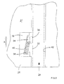
- Referring to figure 2, a
first embodiment 32 of ananti-kickback device 30 is shown schematically. Thedevice 32 comprises a block 34 a portion of which extends into thechannel 24 of the footplate 26 by a relatively small distance beyond the dashed line B in a first position. Asurface 36 of the block is arranged to engage with a side face of the guide rail's rib when the saw is disposed on the guide rail. The block is urged into the first position by aspring 38. In the first position, the distance by which the block'ssurface 36 extends into the channel is sufficient for the surface to contact the rail's rib. - Referring to figure 3, a plan view of the first embodiment is shown in schematic form. The position a guide rail rib would occupy when the saw is disposed on the rail is shown as a dotted
line 22; thisline 22 indicates the rib disposed in thefootplate channel 24. Theblock 34 can move with respect to the footplate 27 in a direction generally parallel to arrow A, since the block slides along asurface 40 which is inclined with respect to theopposite wall 42 of the channel. Thus, the distance between the guide rail rib and thesurface 36 of the block varies depending on the position of the block in thedevice 32. The block can act as a brake by jamming therib 22 between the block'ssurface 36 and opposingsurface 42 of the channel when the footplate moves relative to the rib in an opposite direction to that indicated by arrow A. Conversely, the block imparts a relatively low amount of friction on the rib when the rib moves in a direction parallel to arrow A with respect to thedevice 32. - The
spring 38 urges the block into a position such that theblock 34 engages the rib when there is no relative movement of the rib and footplate. In this manner, the slightest movement of the footplate in a direction opposite to arrow A causes the block to move in a direction generally parallel to A relative to theanti-kickback device 32, thereby reducing the distance between the opposing surface of the block and channel, 36 and 42 respectively, and jamming the rib between the slidingsurface 40, block andchannel surface 42. However, relative movement of the footplate to the rib in a direction indicated by A is permitted because the block offers little friction between the footplate and rib. The spring constant ofspring 40 should be chosen so that the force exerted on the block by the spring is relatively low. - The optimum angle of inclination between the sliding
surface 40 andopposite channel surface 42 is between 4 and 10 degrees and preferably 6.5 degrees. However, any angle between 2 and 15 degrees can be used. - The block and spring are held in position in the anti-kickback device by a topplate, not shown in figure 3, which is arranged to be flush with the
underside surface 27 of thefootplate 26. - In a second, alternative embodiment, shown in figure 4, the block is replaced by a
roller 50. In all other respects, the first and second embodiments operate on the same principle. The roller is cylindrical or drum-shaped so that itscircumferential surface 52 engages with the rib and sliding surface. Figure 5 shows the second embodiment in cross-section along the line 5-5 (figure 4). The roller has a bevellededge 54 which allows the saw to be placed directly on top of the rib (rather than sliding the saw onto the guide rail from one end of the rail). In other words, as the saw is placed on the guide rail, the bevelled edge of theroller 50 allows the rid to move between the roller andsurface 42, gently easing the roller out of the rib's path as the rib and channel engage one another. This action can be assisted if the rib has a rounded edge, in cross-section. - Use of a roller is preferable to a sliding block arrangement as described for the first embodiment. It has been found that a roller is less likely to jam as the saw is moved down a guide rail in direction A: In some cases, the block can twist causing jamming between the block and the rib.
- A third embodiment is shown schematically in figure 6. This embodiment comprises one or
more cam wheels pin contact surface 68 arranged to face an opposite surface of the channel such that a guide rail rib can fit between the contact surface of the cam and guide rail. The cam is rotatably moveable between a first and second position, such that in the first position, the distance between the contact surface of the cam and the opposite surface of the channel is less than the width of the guide rail's rib, and in the second position, the distance between the contact and opposite surface respectively is greater than the width of the channel in which the rib is locatable. - A watch spring (not shown) can be used to urge the cams into a position where the cam engages with the guide rail's rib when the saw is disposed on the rail. The cam should be configured to operate with the same principles as those described above, that is to act a brake by jamming the rib in the channel to prevent relative movement of the rib in one direction, but to allow free movement of the rib in another opposite direction A. Thus, the smallest distance between the cam's
contact surface 68 and the opposite surface of thechannel 42 should be less than the width of the rib fitting into the channel (i.e. when the cam is in the first position, as discussed earlier). - In addition, the anti-kickback device can be provided with a manually
operable button 80, as shown in figure 7. The button is coupled to theroller 50 by apin 82. Preferably, thepin 82 is fixed to the roller so that it can not rotate with respect to the roller, although it is to be understood that non-fixed configuration could also be used. The pin is guided by aslot 84 passing through thefootplate 26. The slot is linear in its longitudinal direction and has a width which is greater than the diameter of the pin to allow relatively free or unhindered movement of the pin therein. The slot can have parallel sides which are angled with respect to the guide rail rib or footplate channel within an angular range arranged to be between zero degrees (that is, parallel to the guide rail rib) and parallel to the slidingsurface 40, with reference to figure 8. - The button provides a means for the user to free or unlock the anti-kickback device should it become jammed during operation. The user is able to rotate the button to free the
roller 50 from theguide rail rib 22 after a jamming event has occurred. Where the roller is fixedly attached to the button, rotation of the button causes the roller to rotate and free itself from the guide rail rib and sliding surfaces between which it has become jammed. - Furthermore, the user can move the roller out of contact with the guide rail rib by pulling the button in a direction which moves the roller along or substantially along the sliding
surface 40. By holding the button in this operative position, the roller is held away from the sliding surface and the anti-kickback device can be overridden. In other words, the user is thereby able to deactivate the anti-kickback device and move the circular saw along the guide rail in a direction opposite to arrow A (see figure 1, for instance) without the anti-kickback device locking the saw's footplate to the guide rail. This is an advantageous feature of the present invention because it allows the user to bring the saw back to a starting position on the guide rail after a cut has been completed without having to lift the saw from and then replace it on the guide rail at the start position. Preferably, the direction in which the button is pulled to deactivate the anti-kickback device (as shown by arrow Z in figure 8) is opposite to the cut direction, that is, opposite to Arrow A. Thus, the user can release the anti-kickback device and pull the saw along the guide rail in a direction opposite to A with one movement or action, and single handed. - The button is moveable to the operative position against the resilience of spring. Releasing the button therefore causes it, and hence the roller, to move to the button's inoperative position, where the roller contactable with the guide rail rib.
- Referring now to figure 9, a
coupling member 92 for coupling thespring 38 to theroller 50 is shown. The coupling member has a generally cup-shaped profile adapted to receive thecircumference 52 of theroller 50. The coupling member also comprisesprotrusions 94 which can form a cavity into which a first end of the spring is received. Anipple 96 can be provided to fit inside the coils of a spring and thereby hold the spring in relation to the coupling member, and hence the roller. A combination of both theprotrusions 94 andnipple 96 are preferred, but either one of these arrangements could be used independently. - A bar or rib-
like protrusion 90 can be arranged on either or both of the footplate and/or a cover or retaining plate of the anti-kickback mechanism for retaining a second end of the spring in relation to the footplate. Referring to figure 10, a bar-like protrusion 90 extends from a retainingplate 98 of theanti-kickback device 30. The retaining plate acts to retain the components of the anti-kickback device on the saw'sfootplate 26, amongst other functions. The rib is arranged to pinch the spring against aportion 93 of the footplate adapted to receive the anti-kickback device. In the case of a coil spring, the rib can be arranged to fit between neighbouring coils of the spring. Afurther protrusion 91 can be disposed on theportion 93 of the footplate to further pinch the spring member. Thus, the second end of the spring can be held in a position relative the saw's footplate. Of course, either or both or theprotrusions - The coupling member and/or the spring
member retaining protrusion 90 act to help prevent the spring from disengaging with components of the anti-kickback device. This can assist with reducing the likelihood of the anti-kickback failing. Thus, the operator is able to utilise the device for long periods without having to service the anti-kickback device - The block, roller or cam can be made from any suitable material, such as metal (steel or aluminium for instance), synthetic plastic (high impact nylon for instance), or resilient material (such as rubber). Factors, such as cost of manufacture, wear rates and coefficient of friction, may influence the choice of material.
- Other embodiments of the present invention will be envisaged by the skilled person. For instance it is perceived that a separate anti-kickback device could be retro-fitted to a plunge-action circular saw's footplate by means of bolts engaging with threaded holes in the footplate, or the like. Furthermore, it is not essential that the anti-kickback device is disposed on the footplate and a series of anti-kickback devices could be disposed on a guide rail arranged to engage with the footplate channel of a circular saw. Yet further, it might be desirable to arrange for an anti-kickback device to operate between the footplate and an alternative portion of the guide rail, other than the longitudinal rib. Still further, it might be possible to provide an anti-kickback device without a spring to urge the jamming device into a first position. For instance, if the block were made from a resilient material, such as rubber, the device could be arranged such that a spring is not necessary - the resilience of the material acts to urge the block into a suitable position. Also, the spring is not limited to a coil spring as shown in the drawings, and other resilient means could be used, such as a leaf spring or a rod of resilient material (rubber, for instance).
Claims (4)
- A hand operated circular saw comprising;
a base plate comprising a channel arranged to cooperate with a guide rail member,
a motor housing,
a gripping portion and a switch for manual operation of a motor disposed in the motor housing, and
a cowl coupled to the base plate and arranged to accommodate at least a portion of a saw blade disposed on an output spindle coupled to the motor,
said output spindle being moveable with respect to the base plate and/or cowl between a first position and a second position thereby providing a plunge-cut action of the circular saw;
the base plate further comprises:a mechanism arranged to cooperate with a portion of a guide rail such that, when the circular saw is disposed on a guide rail, the mechanism offers relatively low friction between the saw and guide rail in a first direction thereby allowing the saw to be moved manually with respect to the guide rail in the first direction, and the mechanism offers relatively high friction between the saw and guide rail in a second direction thereby preventing free movement of the saw with respect to the guide rail in the second direction,characterised in that the mechanism comprises one or more cams urged into a first position by a spring. - Apparatus according to claim 1, wherein, when the cam is in the first position, a portion of the cam extends a distance into a channel of the footplate such that the shortest distance between a contact surface of the cam and the opposite surface of the channel is less than the width of the channel, or less than the width of a rib on a guide rail.
- Apparatus according to claim 2, wherein the cam is moveable between a first and second position, such that,
in the first position a portion of the cam extends a distance into a channel of the footplate such that the shortest distance between a contact surface of the cam and the opposite surface of the channel is less than the width of the channel, and
in the second position, the distance between a contact surface of the cam and the opposite surface of the channel is greater than the width of a rib on a guide rail. - Apparatus according to any one of the preceding claims, wherein at least one said cam is rotatably disposed on a saw's footplate.
Priority Applications (1)
| Application Number | Priority Date | Filing Date | Title |
|---|---|---|---|
| EP07109070.8A EP1842635B1 (en) | 2005-06-01 | 2005-07-05 | Circular saw with anti-kickback device |
Applications Claiming Priority (3)
| Application Number | Priority Date | Filing Date | Title |
|---|---|---|---|
| EP05253356 | 2005-06-01 | ||
| EP05014514A EP1728604B1 (en) | 2005-06-01 | 2005-07-05 | Circular saw with anti-kickback device |
| EP07109070.8A EP1842635B1 (en) | 2005-06-01 | 2005-07-05 | Circular saw with anti-kickback device |
Related Parent Applications (2)
| Application Number | Title | Priority Date | Filing Date |
|---|---|---|---|
| EP05014514.3 Division | 2005-07-05 | ||
| EP05014514A Division EP1728604B1 (en) | 2005-06-01 | 2005-07-05 | Circular saw with anti-kickback device |
Publications (3)
| Publication Number | Publication Date |
|---|---|
| EP1842635A2 true EP1842635A2 (en) | 2007-10-10 |
| EP1842635A3 EP1842635A3 (en) | 2010-12-22 |
| EP1842635B1 EP1842635B1 (en) | 2016-06-15 |
Family
ID=36219081
Family Applications (2)
| Application Number | Title | Priority Date | Filing Date |
|---|---|---|---|
| EP05014514A Not-in-force EP1728604B1 (en) | 2005-06-01 | 2005-07-05 | Circular saw with anti-kickback device |
| EP07109070.8A Not-in-force EP1842635B1 (en) | 2005-06-01 | 2005-07-05 | Circular saw with anti-kickback device |
Family Applications Before (1)
| Application Number | Title | Priority Date | Filing Date |
|---|---|---|---|
| EP05014514A Not-in-force EP1728604B1 (en) | 2005-06-01 | 2005-07-05 | Circular saw with anti-kickback device |
Country Status (5)
| Country | Link |
|---|---|
| US (1) | US20060283024A1 (en) |
| EP (2) | EP1728604B1 (en) |
| AU (1) | AU2006202128A1 (en) |
| GB (1) | GB2426738A (en) |
| WO (1) | WO2006128760A1 (en) |
Cited By (1)
| Publication number | Priority date | Publication date | Assignee | Title |
|---|---|---|---|---|
| US10144148B2 (en) | 2014-08-12 | 2018-12-04 | Robert Bosch Tool Corporation | System and method for kickback detection in a circular saw |
Families Citing this family (6)
| Publication number | Priority date | Publication date | Assignee | Title |
|---|---|---|---|---|
| DE102007027487A1 (en) * | 2007-06-14 | 2008-12-18 | Robert Bosch Gmbh | Brake system for machine tools, and brake actuators |
| DE602007007755D1 (en) * | 2007-07-26 | 2010-08-26 | Black & Decker Inc | footplate |
| EP2018920B1 (en) * | 2007-07-26 | 2011-09-07 | Black & Decker, Inc. | Anti-kickback device |
| EP2018921B1 (en) | 2007-07-26 | 2010-12-22 | Black & Decker, Inc. | Anti-kick device |
| CN106944659A (en) * | 2017-03-31 | 2017-07-14 | 苏州道众机械制造有限公司 | Multi-functional cutter |
| US10875109B1 (en) | 2018-04-30 | 2020-12-29 | Kreg Enterprises, Inc. | Adaptive cutting system |
Citations (1)
| Publication number | Priority date | Publication date | Assignee | Title |
|---|---|---|---|---|
| EP1418018A1 (en) | 2002-11-06 | 2004-05-12 | Festool GmbH | Guide rail for hand held machine-tools and associated stop |
Family Cites Families (10)
| Publication number | Priority date | Publication date | Assignee | Title |
|---|---|---|---|---|
| US1621428A (en) * | 1925-04-11 | 1927-03-15 | Pedersen Florian Bertram | Universal joint |
| DE3341003C2 (en) * | 1983-11-12 | 1986-01-30 | Festo-Maschinenfabrik Gottlieb Stoll, 7300 Esslingen | Guide device for a transportable saw |
| IT8421899V0 (en) * | 1984-05-23 | 1984-05-23 | Black & Decker Inc | HAND TRANSLABLE DISC SAW WITH UNIDIRECTIONAL BRAKING DEVICE. |
| DE3523486A1 (en) * | 1985-07-01 | 1987-01-08 | Guenter Volkmann | Device for backlash-free routing |
| DE4001331A1 (en) * | 1990-01-18 | 1991-07-25 | Reich Maschf Gmbh Karl | Cutting coated wooden etc. workpieces by circular saw - cuts cover layer in two orthogonal directions, and then entire cross=section in opposite cuts |
| US5918521A (en) * | 1994-11-11 | 1999-07-06 | Sartori; James A. | Bifurcated holdown shoe for radial arm saws |
| DE19635527A1 (en) | 1996-08-20 | 1998-02-26 | Black & Decker Inc | Hand-held circular saw |
| EP1410818A1 (en) | 2002-10-14 | 2004-04-21 | Sergio Restelli | Vial for injection and relative safety device |
| US7673549B2 (en) * | 2003-12-03 | 2010-03-09 | H&S Tool, Inc. | Friction linear guide rail assembly for boiler tube cutting apparatus |
| DE102004002275B4 (en) * | 2004-01-16 | 2011-05-19 | Hilti Aktiengesellschaft | Hand tool |
-
2005
- 2005-07-05 EP EP05014514A patent/EP1728604B1/en not_active Not-in-force
- 2005-07-05 EP EP07109070.8A patent/EP1842635B1/en not_active Not-in-force
-
2006
- 2006-03-03 GB GB0604302A patent/GB2426738A/en not_active Withdrawn
- 2006-04-13 WO PCT/EP2006/061602 patent/WO2006128760A1/en active Application Filing
- 2006-05-19 AU AU2006202128A patent/AU2006202128A1/en not_active Abandoned
- 2006-05-25 US US11/441,378 patent/US20060283024A1/en not_active Abandoned
Patent Citations (1)
| Publication number | Priority date | Publication date | Assignee | Title |
|---|---|---|---|---|
| EP1418018A1 (en) | 2002-11-06 | 2004-05-12 | Festool GmbH | Guide rail for hand held machine-tools and associated stop |
Cited By (1)
| Publication number | Priority date | Publication date | Assignee | Title |
|---|---|---|---|---|
| US10144148B2 (en) | 2014-08-12 | 2018-12-04 | Robert Bosch Tool Corporation | System and method for kickback detection in a circular saw |
Also Published As
| Publication number | Publication date |
|---|---|
| US20060283024A1 (en) | 2006-12-21 |
| GB0604302D0 (en) | 2006-04-12 |
| AU2006202128A1 (en) | 2006-12-21 |
| EP1842635B1 (en) | 2016-06-15 |
| EP1728604B1 (en) | 2008-10-15 |
| EP1842635A3 (en) | 2010-12-22 |
| WO2006128760A1 (en) | 2006-12-07 |
| EP1728604A1 (en) | 2006-12-06 |
| GB2426738A (en) | 2006-12-06 |
Similar Documents
| Publication | Publication Date | Title |
|---|---|---|
| EP2018920B1 (en) | Anti-kickback device | |
| AU2008202877B2 (en) | Anti-kickback device | |
| EP1842635B1 (en) | Circular saw with anti-kickback device | |
| US7814818B2 (en) | Modular table saw guarding system riving knife release mechanisms | |
| EP2086731B1 (en) | A modular guard systems for a power saw | |
| US7137326B2 (en) | Translation stop for use in power equipment | |
| US10245754B2 (en) | Miter saw safety device | |
| EP1236530B1 (en) | Blade clamp suitable for reciprocating power tools | |
| EP1764197A2 (en) | Chainsaw with tensioning mechanism | |
| US10442109B2 (en) | Safety device for power cutting tools | |
| US6578461B1 (en) | Saw fence and work feed apparatus | |
| US4637288A (en) | Safety mechanism for saws | |
| US20120118120A1 (en) | Safety device for table saw | |
| US3267973A (en) | Chain saw bar adjusting device | |
| CN1872469B (en) | Anti-kickback device used for circular saw | |
| US20210078196A1 (en) | Saw | |
| US4430795A (en) | Safety device for chain saw | |
| US20060011032A1 (en) | Guarded power circular saw assembly | |
| CA2358863C (en) | Table saw | |
| CA2411920A1 (en) | A rapid set guard system for a radial arm saw | |
| AU2003265727A1 (en) | A guarded power circular saw assembly |
Legal Events
| Date | Code | Title | Description |
|---|---|---|---|
| PUAI | Public reference made under article 153(3) epc to a published international application that has entered the european phase |
Free format text: ORIGINAL CODE: 0009012 |
|
| 17P | Request for examination filed |
Effective date: 20070529 |
|
| AC | Divisional application: reference to earlier application |
Ref document number: 1728604 Country of ref document: EP Kind code of ref document: P |
|
| AK | Designated contracting states |
Kind code of ref document: A2 Designated state(s): AT BE BG CH CY CZ DE DK EE ES FI FR GB GR HU IE IS IT LI LT LU LV MC NL PL PT RO SE SI SK TR |
|
| AX | Request for extension of the european patent |
Extension state: AL BA HR MK YU |
|
| PUAL | Search report despatched |
Free format text: ORIGINAL CODE: 0009013 |
|
| AK | Designated contracting states |
Kind code of ref document: A3 Designated state(s): AT BE BG CH CY CZ DE DK EE ES FI FR GB GR HU IE IS IT LI LT LU LV MC NL PL PT RO SE SI SK TR |
|
| AX | Request for extension of the european patent |
Extension state: AL BA HR MK RS |
|
| AKX | Designation fees paid |
Designated state(s): AT BE BG CH CY CZ DE DK EE ES FI FR GB GR HU IE IS IT LI LT LU LV MC NL PL PT RO SE SI SK TR |
|
| 17Q | First examination report despatched |
Effective date: 20111115 |
|
| GRAP | Despatch of communication of intention to grant a patent |
Free format text: ORIGINAL CODE: EPIDOSNIGR1 |
|
| INTG | Intention to grant announced |
Effective date: 20140903 |
|
| GRAS | Grant fee paid |
Free format text: ORIGINAL CODE: EPIDOSNIGR3 |
|
| GRAP | Despatch of communication of intention to grant a patent |
Free format text: ORIGINAL CODE: EPIDOSNIGR1 |
|
| INTG | Intention to grant announced |
Effective date: 20160316 |
|
| GRAA | (expected) grant |
Free format text: ORIGINAL CODE: 0009210 |
|
| AC | Divisional application: reference to earlier application |
Ref document number: 1728604 Country of ref document: EP Kind code of ref document: P |
|
| AK | Designated contracting states |
Kind code of ref document: B1 Designated state(s): AT BE BG CH CY CZ DE DK EE ES FI FR GB GR HU IE IS IT LI LT LU LV MC NL PL PT RO SE SI SK TR |
|
| REG | Reference to a national code |
Ref country code: CH Ref legal event code: EP Ref country code: GB Ref legal event code: FG4D |
|
| REG | Reference to a national code |
Ref country code: IE Ref legal event code: FG4D |
|
| REG | Reference to a national code |
Ref country code: AT Ref legal event code: REF Ref document number: 806255 Country of ref document: AT Kind code of ref document: T Effective date: 20160715 |
|
| REG | Reference to a national code |
Ref country code: DE Ref legal event code: R096 Ref document number: 602005049542 Country of ref document: DE |
|
| REG | Reference to a national code |
Ref country code: LT Ref legal event code: MG4D |
|
| REG | Reference to a national code |
Ref country code: NL Ref legal event code: MP Effective date: 20160615 |
|
| PG25 | Lapsed in a contracting state [announced via postgrant information from national office to epo] |
Ref country code: FI Free format text: LAPSE BECAUSE OF FAILURE TO SUBMIT A TRANSLATION OF THE DESCRIPTION OR TO PAY THE FEE WITHIN THE PRESCRIBED TIME-LIMIT Effective date: 20160615 Ref country code: LT Free format text: LAPSE BECAUSE OF FAILURE TO SUBMIT A TRANSLATION OF THE DESCRIPTION OR TO PAY THE FEE WITHIN THE PRESCRIBED TIME-LIMIT Effective date: 20160615 |
|
| REG | Reference to a national code |
Ref country code: AT Ref legal event code: MK05 Ref document number: 806255 Country of ref document: AT Kind code of ref document: T Effective date: 20160615 |
|
| PG25 | Lapsed in a contracting state [announced via postgrant information from national office to epo] |
Ref country code: LV Free format text: LAPSE BECAUSE OF FAILURE TO SUBMIT A TRANSLATION OF THE DESCRIPTION OR TO PAY THE FEE WITHIN THE PRESCRIBED TIME-LIMIT Effective date: 20160615 Ref country code: SE Free format text: LAPSE BECAUSE OF FAILURE TO SUBMIT A TRANSLATION OF THE DESCRIPTION OR TO PAY THE FEE WITHIN THE PRESCRIBED TIME-LIMIT Effective date: 20160615 Ref country code: GR Free format text: LAPSE BECAUSE OF FAILURE TO SUBMIT A TRANSLATION OF THE DESCRIPTION OR TO PAY THE FEE WITHIN THE PRESCRIBED TIME-LIMIT Effective date: 20160916 Ref country code: NL Free format text: LAPSE BECAUSE OF FAILURE TO SUBMIT A TRANSLATION OF THE DESCRIPTION OR TO PAY THE FEE WITHIN THE PRESCRIBED TIME-LIMIT Effective date: 20160615 |
|
| PG25 | Lapsed in a contracting state [announced via postgrant information from national office to epo] |
Ref country code: BE Free format text: LAPSE BECAUSE OF NON-PAYMENT OF DUE FEES Effective date: 20160731 |
|
| PG25 | Lapsed in a contracting state [announced via postgrant information from national office to epo] |
Ref country code: CZ Free format text: LAPSE BECAUSE OF FAILURE TO SUBMIT A TRANSLATION OF THE DESCRIPTION OR TO PAY THE FEE WITHIN THE PRESCRIBED TIME-LIMIT Effective date: 20160615 Ref country code: EE Free format text: LAPSE BECAUSE OF FAILURE TO SUBMIT A TRANSLATION OF THE DESCRIPTION OR TO PAY THE FEE WITHIN THE PRESCRIBED TIME-LIMIT Effective date: 20160615 Ref country code: RO Free format text: LAPSE BECAUSE OF FAILURE TO SUBMIT A TRANSLATION OF THE DESCRIPTION OR TO PAY THE FEE WITHIN THE PRESCRIBED TIME-LIMIT Effective date: 20160615 Ref country code: IT Free format text: LAPSE BECAUSE OF FAILURE TO SUBMIT A TRANSLATION OF THE DESCRIPTION OR TO PAY THE FEE WITHIN THE PRESCRIBED TIME-LIMIT Effective date: 20160615 Ref country code: IS Free format text: LAPSE BECAUSE OF FAILURE TO SUBMIT A TRANSLATION OF THE DESCRIPTION OR TO PAY THE FEE WITHIN THE PRESCRIBED TIME-LIMIT Effective date: 20161015 Ref country code: SK Free format text: LAPSE BECAUSE OF FAILURE TO SUBMIT A TRANSLATION OF THE DESCRIPTION OR TO PAY THE FEE WITHIN THE PRESCRIBED TIME-LIMIT Effective date: 20160615 |
|
| PG25 | Lapsed in a contracting state [announced via postgrant information from national office to epo] |
Ref country code: PL Free format text: LAPSE BECAUSE OF FAILURE TO SUBMIT A TRANSLATION OF THE DESCRIPTION OR TO PAY THE FEE WITHIN THE PRESCRIBED TIME-LIMIT Effective date: 20160615 Ref country code: PT Free format text: LAPSE BECAUSE OF FAILURE TO SUBMIT A TRANSLATION OF THE DESCRIPTION OR TO PAY THE FEE WITHIN THE PRESCRIBED TIME-LIMIT Effective date: 20161017 Ref country code: BE Free format text: LAPSE BECAUSE OF FAILURE TO SUBMIT A TRANSLATION OF THE DESCRIPTION OR TO PAY THE FEE WITHIN THE PRESCRIBED TIME-LIMIT Effective date: 20160615 Ref country code: AT Free format text: LAPSE BECAUSE OF FAILURE TO SUBMIT A TRANSLATION OF THE DESCRIPTION OR TO PAY THE FEE WITHIN THE PRESCRIBED TIME-LIMIT Effective date: 20160615 Ref country code: ES Free format text: LAPSE BECAUSE OF FAILURE TO SUBMIT A TRANSLATION OF THE DESCRIPTION OR TO PAY THE FEE WITHIN THE PRESCRIBED TIME-LIMIT Effective date: 20160615 |
|
| REG | Reference to a national code |
Ref country code: CH Ref legal event code: PL |
|
| REG | Reference to a national code |
Ref country code: DE Ref legal event code: R097 Ref document number: 602005049542 Country of ref document: DE |
|
| PG25 | Lapsed in a contracting state [announced via postgrant information from national office to epo] |
Ref country code: MC Free format text: LAPSE BECAUSE OF FAILURE TO SUBMIT A TRANSLATION OF THE DESCRIPTION OR TO PAY THE FEE WITHIN THE PRESCRIBED TIME-LIMIT Effective date: 20160615 |
|
| PLBE | No opposition filed within time limit |
Free format text: ORIGINAL CODE: 0009261 |
|
| STAA | Information on the status of an ep patent application or granted ep patent |
Free format text: STATUS: NO OPPOSITION FILED WITHIN TIME LIMIT |
|
| PG25 | Lapsed in a contracting state [announced via postgrant information from national office to epo] |
Ref country code: CH Free format text: LAPSE BECAUSE OF NON-PAYMENT OF DUE FEES Effective date: 20160731 Ref country code: LI Free format text: LAPSE BECAUSE OF NON-PAYMENT OF DUE FEES Effective date: 20160731 Ref country code: FR Free format text: LAPSE BECAUSE OF NON-PAYMENT OF DUE FEES Effective date: 20160816 |
|
| REG | Reference to a national code |
Ref country code: FR Ref legal event code: ST Effective date: 20170331 |
|
| REG | Reference to a national code |
Ref country code: IE Ref legal event code: MM4A |
|
| 26N | No opposition filed |
Effective date: 20170316 |
|
| PG25 | Lapsed in a contracting state [announced via postgrant information from national office to epo] |
Ref country code: DK Free format text: LAPSE BECAUSE OF FAILURE TO SUBMIT A TRANSLATION OF THE DESCRIPTION OR TO PAY THE FEE WITHIN THE PRESCRIBED TIME-LIMIT Effective date: 20160615 |
|
| PG25 | Lapsed in a contracting state [announced via postgrant information from national office to epo] |
Ref country code: IE Free format text: LAPSE BECAUSE OF NON-PAYMENT OF DUE FEES Effective date: 20160705 |
|
| PG25 | Lapsed in a contracting state [announced via postgrant information from national office to epo] |
Ref country code: LU Free format text: LAPSE BECAUSE OF NON-PAYMENT OF DUE FEES Effective date: 20160705 Ref country code: SI Free format text: LAPSE BECAUSE OF FAILURE TO SUBMIT A TRANSLATION OF THE DESCRIPTION OR TO PAY THE FEE WITHIN THE PRESCRIBED TIME-LIMIT Effective date: 20160615 |
|
| PG25 | Lapsed in a contracting state [announced via postgrant information from national office to epo] |
Ref country code: HU Free format text: LAPSE BECAUSE OF FAILURE TO SUBMIT A TRANSLATION OF THE DESCRIPTION OR TO PAY THE FEE WITHIN THE PRESCRIBED TIME-LIMIT; INVALID AB INITIO Effective date: 20050705 Ref country code: CY Free format text: LAPSE BECAUSE OF FAILURE TO SUBMIT A TRANSLATION OF THE DESCRIPTION OR TO PAY THE FEE WITHIN THE PRESCRIBED TIME-LIMIT Effective date: 20160615 |
|
| PG25 | Lapsed in a contracting state [announced via postgrant information from national office to epo] |
Ref country code: TR Free format text: LAPSE BECAUSE OF FAILURE TO SUBMIT A TRANSLATION OF THE DESCRIPTION OR TO PAY THE FEE WITHIN THE PRESCRIBED TIME-LIMIT Effective date: 20160615 |
|
| PG25 | Lapsed in a contracting state [announced via postgrant information from national office to epo] |
Ref country code: BG Free format text: LAPSE BECAUSE OF FAILURE TO SUBMIT A TRANSLATION OF THE DESCRIPTION OR TO PAY THE FEE WITHIN THE PRESCRIBED TIME-LIMIT Effective date: 20160615 |
|
| PGFP | Annual fee paid to national office [announced via postgrant information from national office to epo] |
Ref country code: DE Payment date: 20180619 Year of fee payment: 14 |
|
| PGFP | Annual fee paid to national office [announced via postgrant information from national office to epo] |
Ref country code: GB Payment date: 20180704 Year of fee payment: 14 |
|
| REG | Reference to a national code |
Ref country code: DE Ref legal event code: R119 Ref document number: 602005049542 Country of ref document: DE |
|
| GBPC | Gb: european patent ceased through non-payment of renewal fee |
Effective date: 20190705 |
|
| PG25 | Lapsed in a contracting state [announced via postgrant information from national office to epo] |
Ref country code: DE Free format text: LAPSE BECAUSE OF NON-PAYMENT OF DUE FEES Effective date: 20200201 Ref country code: GB Free format text: LAPSE BECAUSE OF NON-PAYMENT OF DUE FEES Effective date: 20190705 |