EP1842598B1 - Blasting discharge jet - Google Patents
Blasting discharge jet Download PDFInfo
- Publication number
- EP1842598B1 EP1842598B1 EP07004750A EP07004750A EP1842598B1 EP 1842598 B1 EP1842598 B1 EP 1842598B1 EP 07004750 A EP07004750 A EP 07004750A EP 07004750 A EP07004750 A EP 07004750A EP 1842598 B1 EP1842598 B1 EP 1842598B1
- Authority
- EP
- European Patent Office
- Prior art keywords
- section
- flow
- accordance
- discharge nozzle
- agent discharge
- Prior art date
- Legal status (The legal status is an assumption and is not a legal conclusion. Google has not performed a legal analysis and makes no representation as to the accuracy of the status listed.)
- Active
Links
Images


Classifications
-
- B—PERFORMING OPERATIONS; TRANSPORTING
- B24—GRINDING; POLISHING
- B24C—ABRASIVE OR RELATED BLASTING WITH PARTICULATE MATERIAL
- B24C1/00—Methods for use of abrasive blasting for producing particular effects; Use of auxiliary equipment in connection with such methods
- B24C1/003—Methods for use of abrasive blasting for producing particular effects; Use of auxiliary equipment in connection with such methods using material which dissolves or changes phase after the treatment, e.g. ice, CO2
-
- B—PERFORMING OPERATIONS; TRANSPORTING
- B24—GRINDING; POLISHING
- B24C—ABRASIVE OR RELATED BLASTING WITH PARTICULATE MATERIAL
- B24C5/00—Devices or accessories for generating abrasive blasts
- B24C5/02—Blast guns, e.g. for generating high velocity abrasive fluid jets for cutting materials
- B24C5/04—Nozzles therefor
-
- B—PERFORMING OPERATIONS; TRANSPORTING
- B05—SPRAYING OR ATOMISING IN GENERAL; APPLYING FLUENT MATERIALS TO SURFACES, IN GENERAL
- B05B—SPRAYING APPARATUS; ATOMISING APPARATUS; NOZZLES
- B05B1/00—Nozzles, spray heads or other outlets, with or without auxiliary devices such as valves, heating means
- B05B1/02—Nozzles, spray heads or other outlets, with or without auxiliary devices such as valves, heating means designed to produce a jet, spray, or other discharge of particular shape or nature, e.g. in single drops, or having an outlet of particular shape
- B05B1/04—Nozzles, spray heads or other outlets, with or without auxiliary devices such as valves, heating means designed to produce a jet, spray, or other discharge of particular shape or nature, e.g. in single drops, or having an outlet of particular shape in flat form, e.g. fan-like, sheet-like
Definitions
- the invention relates to a Strahlstoffaustragsdüse, in particular for dry ice blasting, with the features of the preamble of claim 1.
- Radiation discharge nozzles are used in discharge devices of particle beam devices.
- EP 0414863 B1 and from DE 2064003 Strahlstoffaustragsdüsen are known with a converging in the flow direction of the inlet portion, followed by a narrowest cross-section in the flow direction and a diverging in the flow direction follower section.
- This Strahlstoffschaustragsdüsen be used especially for particle beam devices in which a mixture of compressed air and blasting medium is discharged.
- soiled surfaces are cleaned.
- dry ice particles are used as blasting agents.
- a particularly gentle cleaning of soiled surfaces is made possible.
- dry ice blasting equipment for cleaning is a particularly gentle method, because the surfaces of the dry ice particles from the dirt, but by the soft Texture of the particles and the dissolution of the ice crystals in the atmosphere immediately after impacting the surface damage to the surface is prevented.
- Known blasting agent discharge nozzles essentially have a converging inlet zone and a diverging outlet zone with a narrowest cross section therebetween. This gives the particles an uneven acceleration, different in direction and speed. This is particularly noticeable in dry ice particles, which rely on a uniformly aligned carrier air flow due to their relatively low mass for a uniform discharge from the nozzle. Therefore, only an unsatisfactory jet pattern and thus a rather low area cleaning performance could be achieved with dry ice blasting devices with these blasting agent discharge nozzles.
- the cylindrical portion whose length is at least 20 mm, it is achieved that the particles are carried on a minimum length within the Strahlstoffaustragsdüse on a rectified in the cylindrical section carrier air flow and thus experience uniform acceleration on this minimum distance.
- the nozzle is constructed in several parts, wherein at least part of the cylindrical section and the section with increasing cross-sectional area in the flow direction are combined to form an assembly. This makes it possible to use this expensive to manufacture and therefore expensive assembly of the nozzle in various combinations.
- first assembly at least a part of the cylindrical section and the section with increasing cross-sectional area in the flow direction are combined to form a first assembly and the converging in the flow direction inlet section with in the flow direction following narrowest cross-section and possibly diverging in the flow direction following section to a second module are.
- the second assemblies differ from each other by the narrowest cross-section, different impact pressures are selected depending on the sensitivity of the surface to be cleaned.
- the section adjoining the cylindrical section in the flow direction increases in width in the flow direction in the direction of flow and decreases in height.
- the particle flow is additionally uniformed and thus an even clearer delimited cleaning field becomes uniform irradiated with particles.
- the grooves have their common starting point on the center of the boundary line between the cylindrical portion and subsequent section.
- the nozzle contains means to connect it with its converging inlet section to the gun or the outlet hose of a particle unit, in particular a dry ice blasting unit.
- the first assembly with a cylindrical portion and with the portion with increasing cross-sectional area in the flow direction in the region of the cylindrical portion has a cylindrical outside shape and can be connected by means of a union nut to the second assembly.
- the invention also relates to a particle beam device for dispensing a mixture of compressed air and dry ice, wherein the particle beam device is connectable to a source of compressed air and has a supply of particles and a metering device, with which the particles of the compressed air can be admixed, and a discharge device to which a supply line for compressed air and particles can be connected, wherein the discharge device has a Strahlstoffaustragsdüse of the aforementioned type.
- the particles of the particle beam device are dry ice particles.
- FIGS. 1 to 5 is a Strahlkaraustragsdüse invention shown schematically. How out FIG. 2 and FIG. 5 ersichtllich, the Strahlkaraustragsdüse invention has a converging in the flow direction inlet portion 1, followed in the flow direction successively a narrowest cross-section 2, a diverging in the flow direction following section 3, a cylindrical section 4 and a section 5 with increasing in the flow direction cross-sectional area 6.
- the convergent inlet section 1 and the diverging secondary section 3 each have a conical inner contour.
- the length of the cylindrical portion 4 is 80 mm, while the length of the portion 5 is 200 mm.
- the nozzle is constructed in several parts and comprises a first assembly 7, which has the cylindrical section 4 and the section 5 with increasing cross-sectional area in the flow direction, and a second assembly 16, the converging inlet section 1, the narrowest cross-section 2 and the downstream divergent section 3 has.
- the first assembly 7 consists of two half shells 8 and 9, which are designed identically. The identical construction allows a particularly inexpensive production of the nozzle.
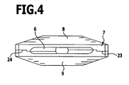
- the identical half-shells 8, 9 have with particular advantage on one side elevations or projections 23 and on symmetrically opposite side to complementary depressions or recesses 24, so that in a simple manner a precisely fitting Assembly of identical parts is possible, as out FIG. 4 is apparent.
- grooves 11 are milled on the two flat inner surfaces of the section 5 in the longitudinal direction, the radial from the center of the boundary line between cylindrical section 4 and subsequent section 5 to the nozzle exit edge 22 symmetrical to the longitudinal axis of the nozzle in the flow direction apart.
- the Strahlstoffschaustragsdüse also has means 12 to connect them with their converging inlet portion of the gun 13 or the outlet hose 14 of a dry ice blasting machine 15.
- a union nut 17 is used to attach the first assembly 7 to the second assembly 16. It has on its outside roughened gripping surfaces 18, so that the union nut 17 can also be attached or detached by hand.
- the first assembly 7 is rotatably mounted on the second assembly 16 and can be changed by simply loosening and then re-tightening the nut 17 in the short term by the operator in their orientation.
- a gun 13 it is thus possible to achieve the orientation of the flat jet at any angle to the handle, thus achieving a particularly simple and fatigue-free for the operator guiding the Strahlstoffschaustragsdüse.
- the dry ice blasting device comprises a metering device 19 which is connectable via a feed line 20 for compressed air with a compressed air source not shown here.
- a reservoir 21 dry ice particles are stored, which are mixed via the metering device 19 of the compressed air.
- the mixture of compressed air and dry ice is passed via the supply line 14 to the gun 13.
- the gun 13 has a coupling nozzle 22 for connecting the Strahlstoffaustragsdüse.
Abstract
Description
Die Erfindung betrifft eine Strahlmittelaustragsdüse, insbesondere zum Trockeneisstrahlen, mit den Merkmalen des Oberbegriffes von Patentanspruch 1.The invention relates to a Strahlmittelaustragsdüse, in particular for dry ice blasting, with the features of the preamble of claim 1.
Strahimittelaustragsdüsen werden bei Austragsvorrichtungen von Partikelstrahlgeräten verwendet. Aus
Diese Strahlmittelaustragsdüsen werden vor allem für Partikelstrahlvorrichtungen verwendet, bei denen ein Gemisch aus Druckluft und Strahlmittel ausgetragen wird.This Strahlmittelaustragsdüsen be used especially for particle beam devices in which a mixture of compressed air and blasting medium is discharged.
Mit dem Gemisch aus Druckluft und Strahlmittel werden beispielsweise verschmutzte Oberflächen gereinigt. Als Strahlmittel kommen dabei insbesondere Trockeneispartikel zum Einsatz. Mit diesen Trockeneispartikeln wird eine besonders schonende Reinigung verschmutzter Oberflächen ermöglicht. Bei der Verwendung von Trockeneisstrahlvorrichtungen zur Reinigung handelt es sich um eine besonders schonende Methode, weil die Oberflächen durch die Trockeneispartikel zwar vom Schmutz befreit, jedoch durch die weiche Beschaffenheit der Partikel und das Auflösen der Eiskristalle in der Atmosphäre unmittelbar nach Auftreffen auf die Oberfläche eine Beschädigung der Oberfläche verhindert wird.With the mixture of compressed air and blasting agent, for example, soiled surfaces are cleaned. In particular, dry ice particles are used as blasting agents. With these dry ice particles, a particularly gentle cleaning of soiled surfaces is made possible. When using dry ice blasting equipment for cleaning is a particularly gentle method, because the surfaces of the dry ice particles from the dirt, but by the soft Texture of the particles and the dissolution of the ice crystals in the atmosphere immediately after impacting the surface damage to the surface is prevented.
Bei solchen Partikelstrahlreinigungsgeräten, insbesondere bei Trockeneisstrahlreinigungsgeräten, kommt der Ausbildung der Strahlmittelaustragsdüsen eine besondere Bedeutung zu, weil durch die Innengeometrie der Austragsdüsen die Auftreffrichtung und -geschwindigkeit der Trockeneispartikel entscheidend beeinflusst wird.In such particle jet cleaning devices, especially in dry ice blasting equipment, the formation of the blasting agent discharge nozzles is of particular importance, because the impact direction and speed of the dry ice particles are decisively influenced by the internal geometry of the discharge nozzles.
Bekannte Strahlmittelaustragsdüsen weisen im Wesentlichen eine konvergierende Eintrittszone und eine divergierende Austrittszone auf mit einem dazwischen liegenden engsten Querschnitt. Dadurch erhalten die Partikel eine ungleichmäßige, nach Richtung und Geschwindigkeit unterschiedliche Beschleunigung. Dieses macht sich besonders bei Trockeneispartikeln bemerkbar, die aufgrund ihrer relativ geringen Masse für einen gleichmäßigen Austrag aus der Düse auf einen gleichmäßig ausgerichteten Trägerluftstrom angewiesen sind. Mit diesen Strahlmittelaustragsdüsen konnte deshalb bei Trockeneisstrahlvorrichtungen nur ein unbefriedigendes Strahlbild und damit eine recht geringe Flächenreinigungsleistung erreicht werden.Known blasting agent discharge nozzles essentially have a converging inlet zone and a diverging outlet zone with a narrowest cross section therebetween. This gives the particles an uneven acceleration, different in direction and speed. This is particularly noticeable in dry ice particles, which rely on a uniformly aligned carrier air flow due to their relatively low mass for a uniform discharge from the nozzle. Therefore, only an unsatisfactory jet pattern and thus a rather low area cleaning performance could be achieved with dry ice blasting devices with these blasting agent discharge nozzles.
Aus
Erfindungsgemäß wird dazu eine Strahlmittelaustragsdüse, insbesondere zum Trockeneisstrahien vorgeschlagen mit den Merkmalen des Patentanspruches 1.According to the invention a Strahlmittelaustragsdüse, in particular for Trockeneisstrahien proposed with the features of claim 1.
Durch den zylindrischen Abschnitt, dessen Länge mindestens 20 mm beträgt, wird erreicht, dass die Partikel auf einer Mindestlänge innerhalb der Strahlmittelaustragsdüse auf einem in dem zylindrischen Abschnitt gleichgerichteten Trägerluftstrom getragen werden und damit auf dieser Mindeststrecke eine gleichmäßige Beschleunigung erfahren.By the cylindrical portion whose length is at least 20 mm, it is achieved that the particles are carried on a minimum length within the Strahlmittelaustragsdüse on a rectified in the cylindrical section carrier air flow and thus experience uniform acceleration on this minimum distance.
Dies führt zu einer Stabilisierung der Strahlmittelströmung, so dass die Partikel auf dem letzten Abschnitt der Strahlmittelaustragsdüse vor der Austragsöffnung deutlich stabiler strömen, als dies bei einer Strahlmittelaustragsdüse ohne zylindrischen Abschnitt oder mit einem deutlich kürzeren zylindrischen Abschnitt der Fall wäre. Die zu reinigende Oberfläche wird deshalb von den Partikeln nach dem Austritt aus der Düse mit gleichmäßigerem Aufpralldruck beaufschlagt, so dass über dem angestrahlten Oberflächenbereich eine gleichmäßige und intensive Reinigung erfolgt.This leads to a stabilization of the blasting agent flow, so that the particles flow much more stably on the last section of the blasting agent discharge nozzle in front of the discharge opening, than would be the case with a blasting agent discharge nozzle without cylindrical section or with a significantly shorter cylindrical section. The surface to be cleaned is therefore acted upon by the particles after discharge from the nozzle with a more uniform impact pressure, so that over the illuminated surface area a uniform and intensive cleaning takes place.
Eine besonders hohe Flächenleistung auch bei Einsatz von Kompressoren mit geringerer Laufleistung ergibt sich dadurch, dass sich an den engsten Querschnitt vor dem zylindrischen Abschnitt ein in Strömungsrichtung divergierender Abschnitt anschließt.A particularly high area performance even when using compressors with lower mileage results from the fact that to the narrowest cross section in front of the cylindrical portion connects a diverging in the flow direction section.
Besonders gute Ergebnisse werden bei Strahlmittelaustragsdüsen erreicht, bei denen das Verhältnis der Längen zwischen dem Abschnitt mit in Strömungsrichtung zunehmender Querschnittsfläche und dem zylindrischen Abschnitt höchstens 4 : 1, vorzugsweise höchstens 2,5 :1 beträgt.Particularly good results are achieved in the case of jet discharge nozzles in which the ratio of the lengths between the section with the cross-sectional area increasing in the direction of flow and the cylindrical section is at most 4: 1, preferably at most 2.5: 1.
Um bei Verschleißerscheinungen an einzelnen Bereichen der Düse oder bei gewünschten unterschiedlichen Strahlcharakteristiken nicht die gesamte Düse erneuern bzw. wechseln zu müssen, ist es günstig, wenn die Düse mehrteilig aufgebaut ist, wobei zumindest ein Teil des zylindrischen Abschnitts und der Abschnitt mit in Strömungsrichtung zunehmender Querschnittsfläche zu einer Baugruppe zusammengefasst sind. Dadurch ist es möglich, diese aufwendig herzustellende und daher teuere Baugruppe der Düse in verschiedenen Kombinationen zu verwenden.In order to avoid having to renew or replace the entire nozzle in the case of signs of wear on individual regions of the nozzle or with desired different jet characteristics, it is favorable if the nozzle is constructed in several parts, wherein at least part of the cylindrical section and the section with increasing cross-sectional area in the flow direction are combined to form an assembly. This makes it possible to use this expensive to manufacture and therefore expensive assembly of the nozzle in various combinations.
Besonders vorteilhaft ist es, wenn zumindest ein Teil des zylindrischen Abschnitts und der Abschnitt mit in Strömungsrichtung zunehmender Querschnittsfläche zu einer ersten Baugruppe zusammengefasst sind und der in Strömungsrichtung konvergierende Eintrittsabschnitt mit in Strömungsrichtung anschließendem engstem Querschnitt und gegebenenfalls mit in Strömungsrichtung divergierendem Folgeabschnitt zu einer zweiten Baugruppe zusammengefasst sind. Dadurch können beispielsweise durch Verwendung der gleichen ersten Baugruppe mit unterschiedlichen zweiten Baugruppen, wobei sich die zweiten Baugruppen untereinander durch den engsten Querschnitt unterscheiden, unterschiedliche Aufpralldrücke je nach Empfindlichkeit der zu reinigenden Oberfläche ausgewählt werden.It is particularly advantageous if at least a part of the cylindrical section and the section with increasing cross-sectional area in the flow direction are combined to form a first assembly and the converging in the flow direction inlet section with in the flow direction following narrowest cross-section and possibly diverging in the flow direction following section to a second module are. As a result, for example, by using the same first assembly with different second assemblies, the second assemblies differ from each other by the narrowest cross-section, different impact pressures are selected depending on the sensitivity of the surface to be cleaned.
Ein in der Herstellung besonders preiswerter Aufbau ergibt sich dann, wenn die erste Baugruppe zwei identische Halbschalen aufweist.A construction that is particularly inexpensive to produce results when the first assembly has two identical half-shells.
Um eine möglichst breite Austrittsöffnung mit relativ schmaler Höhe zu erhalten, ist es vorteilhaft, wenn der in Strömungsrichtung an den zylindrischen Abschnitt anschließende Abschnitt mit in Strömungsrichtung zunehmender Querschnittsfläche in Strömungsrichtung in der Breite zunimmt und in der Höhe abnimmt.In order to obtain the widest possible outlet opening with a relatively narrow height, it is advantageous if the section adjoining the cylindrical section in the flow direction increases in width in the flow direction in the direction of flow and decreases in height.
Im Falle, dass der an den zylindrischen Abschnitt anschließende Abschnitt an seinen ebenen Innenflächen in Längsrichtung Nuten aufweist, die strahlenförmig und symmetrisch zu der Längsachse der Düse in Strömungsrichtung bis zur Düsenausschnittskante auseinander laufen, wird der Partikelstrom zusätzlich vergleichmäßigt und damit ein noch klarer abgegrenztes Reinigungsfeld gleichmäßig mit Partikeln bestrahlt.In the case in which the section adjoining the cylindrical section has grooves on its flat inner surfaces in the longitudinal direction, which diverge radially and symmetrically with respect to the longitudinal axis of the nozzle in the flow direction up to the nozzle cut-out edge, the particle flow is additionally uniformed and thus an even clearer delimited cleaning field becomes uniform irradiated with particles.
Dabei ist es besonders vorteilhaft, wenn die Nuten ihren gemeinsamen Anfangspunkt auf dem Mittelpunkt der Grenzlinie zwischen zylindrischem Abschnitt und darauf folgendem Abschnitt haben.It is particularly advantageous if the grooves have their common starting point on the center of the boundary line between the cylindrical portion and subsequent section.
Ein vorteilhafter Aufbau ergibt sich, wenn die Düse Einrichtungen enthält, um sie mit ihrem konvergierenden Eintrittsabschnitt an die Pistole oder den Austrittsschlauch eines Partikelgerätes, insbesondere eines Trockeneisstrahlgerätes, anzuschließen.An advantageous construction results when the nozzle contains means to connect it with its converging inlet section to the gun or the outlet hose of a particle unit, in particular a dry ice blasting unit.
Von besonderem Vorteil ist es, wenn die erste Baugruppe mit zylindrischem Abschnitt und mit dem Abschnitt mit in Strömungsrichtung zunehmender Querschnittsfläche im Bereich des zylindrischen Abschnitts außen eine zylindrische Form aufweist und mit Hilfe einer Überwurfmutter an die zweite Baugruppe angeschlossen werden kann.It is particularly advantageous if the first assembly with a cylindrical portion and with the portion with increasing cross-sectional area in the flow direction in the region of the cylindrical portion has a cylindrical outside shape and can be connected by means of a union nut to the second assembly.
Insbesondere bei Verwendung einer Pistole mit Handgriff ist es zur optimalen Auswahl einer gewünschten Strahlrichtung von Vorteil, wenn die erste Baugruppe an der zweiten Baugruppe verdrehbar befestigbar ist.In particular, when using a pistol with handle, it is for optimum selection of a desired beam direction of advantage when the first assembly is rotatably fastened to the second module.
Die Erfindung betrifft außerdem eine Partikelstrahlvorrichtung zum Abgeben von einem Gemisch aus Druckluft und Trockeneis, wobei die Partikelstrahlvorrichtung mit einer Druckluftquelle verbindbar ist und einen Vorrat von Partikeln aufweist sowie eine Dosiereinrichtung, mit der die Partikel der Druckluft beigemischt werden können, und eine Austragsvorrichtung, an die eine Zuleitung für Druckluft und Partikel anschließbar ist, wobei die Austragsvorrichtung eine Strahlmittelaustragsdüse der voranstehend genannten Art aufweist.The invention also relates to a particle beam device for dispensing a mixture of compressed air and dry ice, wherein the particle beam device is connectable to a source of compressed air and has a supply of particles and a metering device, with which the particles of the compressed air can be admixed, and a discharge device to which a supply line for compressed air and particles can be connected, wherein the discharge device has a Strahlmittelaustragsdüse of the aforementioned type.
Besonders vorteilhaft ist es, wenn es sich bei den Partikeln der Partikelstrahlvorrichtung um Trockeneispartikel handelt.It is particularly advantageous if the particles of the particle beam device are dry ice particles.
Gerade bei der Reinigung mit Trockeneispartikeln kommen die Vorteile der Erfindung besonders zur Geltung.Especially when cleaning with dry ice particles, the advantages of the invention come particularly to advantage.
Nachfolgend wird die Erfindung anhand von bevorzugten Ausführungsbeispielen näher beschrieben. Es zeigen:
- Figur 1:
- eine Draufsicht auf eine erfindungsgemäße Strahlmittelaustragsdüse;
- Figur 2:
- einen Längsschnitt der Strahlmittelaustragsdüse längs der Linie 2-2 in
Figur 1 ; - Figur 3:
- eine Seitenansicht der Strahlmittelaustragsdüse;
- Figur 4:
- eine Vorderansicht der Strahlmittelaustragsdüse;
- Figur 5:
- eine Schnittansicht der Strahlmittelaustragsdüse längs der Linie 5-5 in
Figur 3 ; - Figur 6:
- eine schematische Darstellung einer erfindungsgemäßen Trockeneisstrahlvorrichtung.
- FIG. 1:
- a plan view of a Strahlmittelaustragsdüse invention;
- FIG. 2:
- a longitudinal section of the Strahlmittelaustragsdüse along the line 2-2 in
FIG. 1 ; - FIG. 3:
- a side view of the Strahlmittelaustragsdüse;
- FIG. 4:
- a front view of the Strahlmittelaustragsdüse;
- FIG. 5:
- a sectional view of the Strahlmittelaustragsdüse along the line 5-5 in
FIG. 3 ; - FIG. 6:
- a schematic representation of a dry ice blasting device according to the invention.
In den
Die Düse ist mehrteilig aufgebaut und umfasst eine erste Baugruppe 7, welche den zylindrischen Abschnitt 4 und den Abschnitt 5 mit in Strömungsrichtung zunehmender Querschnittsfläche aufweist, sowie eine zweite Baugruppe 16, die den konvergierenden Eintrittsabschnitt 1, den engsten Querschnitt 2 und den in Strömungsrichtung divergierenden Folgeabschnitt 3 aufweist. Die erste Baugruppe 7 besteht aus zwei Halbschalen 8 und 9, welche identisch ausgestaltet sind. Die identische Bauweise ermöglicht eine besonders preiswerte Herstellung der Düse.The nozzle is constructed in several parts and comprises a first assembly 7, which has the
Die identischen Halbschalen 8, 9 weisen mit besonderem Vorteil auf einer Seite Erhebungen oder Vorsprünge 23 und an symmetrisch gegenüberliegender Seite dazu komplementäre Vertiefungen oder Rücksprünge 24 auf, so dass auf einfache Weise eine passgenaue Montage der identischen Teile möglich ist, wie aus
Wie in den
Um den so entstehenden Strom von Trockeneispartikeln, der bereits im vorhergehenden zylindrischen Abschnitt 4 gleichmäßig beschleunigt wurde, weiterhin möglichst gleichmäßig und turbulenzfrei strömen zu lassen, sind an den beiden ebenen Innenflächen des Abschnittes 5 in Längsrichtung Nuten 11 eingefräst, die strahlenförmig vom Mittelpunkt der Grenzlinie zwischen zylindrischem Abschnitt 4 und darauf folgendem Abschnitt 5 bis zur Düsenaustrittskante 22 symmetrisch zur Längsachse der Düse in Strömungsrichtung auseinander laufen.In order to allow the resulting stream of dry ice particles, which has been uniformly accelerated even in the preceding
Die Strahlmittelaustragsdüse weist außerdem Einrichtungen 12 auf, um sie mit ihrem konvergierenden Eintrittsabschnitt an die Pistole 13 oder den Austrittsschlauch 14 eines Trockeneisstrahlgerätes 15 anzuschließen.The Strahlmittelaustragsdüse also has means 12 to connect them with their converging inlet portion of the
Eine Überwurfmutter 17 dient der Befestigung der ersten Baugruppe 7 an der zweiten Baugruppe 16. Sie weist an ihrer Außenseite aufgerauhte Griffflächen 18 auf, so dass die Überwurfmutter 17 auch von Hand befestigt bzw. gelöst werden kann. Die erste Baugruppe 7 ist an der zweiten Baugruppe 16 verdrehbar befestigt und kann durch einfaches Lösen und anschließendes Wiederanziehen der Überwurfmutter 17 kurzfristig durch die Bedienperson in ihrer Ausrichtung verändert werden. Bei Verwendung einer Pistole 13 ist es damit möglich, die Ausrichtung des Flachstrahles in beliebigem Winkel zum Handgriff zu erreichen, um somit ein besonders einfaches und damit für die Bedienperson ermüdungsfreies Führen der Strahlmittelaustragsdüse zu erreichen.A
Wie aus
Claims (14)
- Blasting agent discharge nozzle, in particular, for dry ice blasting, with an inlet section (1) converging in the direction of flow, which is followed in the direction of flow by a narrowest cross section (2), a cylindrical section (4) and a section (5) having a cross-sectional area (6) that increases in the direction of flow, characterized in that the length of the cylindrical section (4) is at least 20 mm, and in that the narrowest cross section (2) is followed, before the cylindrical section (4), by a section that diverges in the direction of flow.
- Blasting agent discharge nozzle in accordance with claim 1, characterized in that the ratio of the lengths between the section (5) having a cross-sectional area that increases in the direction of flow and the cylindrical section (4) is at most 4 : 1.
- Blasting agent discharge nozzle in accordance with claim 1 or 2, characterized in that the ratio of the lengths between the section (5) having a cross-sectional area (6) that increases in the direction of flow and the cylindrical section (4) is at most 2.5 : 1
- Blasting agent discharge nozzle in accordance with any one of the preceding claims, characterized in that the nozzle is of multipart construction, at least part of the cylindrical section (4) and the section (5) having a cross-sectional area (6) that increases in the direction of flow being combined to form an assembly (7).
- Blasting agent discharge nozzle in accordance with any one of the preceding claims, characterized in that at least part of the cylindrical section (4) and the section (5) having a cross-sectional area (6) that increases in the direction of flow are combined to form a first assembly (7), and in that the inlet section (1) converging in the direction of flow, the narrowest cross section (2) following in the direction of flow, and the following section (3) diverging in the direction of flow are combined to form a second assembly (16).
- Blasting agent discharge nozzle in accordance with claim 4 or 5, characterized in that the first assembly (7) comprises two identical half shells (8, 9).
- Blasting agent discharge nozzle in accordance with any one of the preceding claims, characterized in that the section (5) following the cylindrical section (4) in the direction of flow and having a cross-sectional area (6) that increases in the direction of flow increases in width and decreases in height in the direction of flow.
- Blasting agent discharge nozzle in accordance with any one of the preceding claims, characterized in that the section (5) following the cylindrical section (4) has on its flat inner surfaces in the longitudinal direction grooves (11), which diverge from one another radially and symmetrically in relation to the longitudinal axis of the nozzle in the direction of flow up to the nozzle outlet edge (22).
- Blasting agent discharge nozzle in accordance with claim 8, characterized in that the grooves (11) have their common starting point on the midpoint of the boundary line between cylindrical section (4) and following section (5).
- Blasting agent discharge nozzle in accordance with any one of claims 5 to 9, characterized in that the first assembly (7) with the cylindrical section (4) and with the section (5) having a cross-sectional area (6) that increases in the direction of flow has an exterior cylindrical shape in the region of the cylindrical section (4) and can be connected to the second assembly (16) by means of a union nut (17).
- Blasting agent discharge nozzle in accordance with any one of claims 5 to 10, characterized in that the first assembly (7) is rotatably attachable to the second assembly (16).
- Blasting agent discharge nozzle in accordance with any one of the preceding claims, characterized in that the nozzle has devices (12) for connecting it with its converging inlet section (1) to the gun (13) or the outlet hose (14) of a particle blasting apparatus, in particular, a dry ice blasting apparatus (15).
- Particle blasting apparatus for discharging a mixture of compressed air and dry ice, the particle blasting apparatus being connectable to a source of compressed air and comprising a supply of particles and a metering device (19) with which the particles can be added to the compressed air, and a discharge device to which a feed line for compressed air and particles is connectable, characterized in that the discharge device comprises a blasting agent discharge nozzle in accordance with any one of the preceding claims.
- Particle blasting apparatus in accordance with claim 13, characterized in that the particles are dry ice particles.
Applications Claiming Priority (1)
| Application Number | Priority Date | Filing Date | Title |
|---|---|---|---|
| DE102006015805A DE102006015805A1 (en) | 2006-04-03 | 2006-04-03 | Blasting adhesive e.g. dry ice particle, delivering nozzle for use with particle blasting device, has transverse and cylindrical sections and third section attached to inflow section, where cylindrical section`s length is twenty millimeter |
Publications (2)
| Publication Number | Publication Date |
|---|---|
| EP1842598A1 EP1842598A1 (en) | 2007-10-10 |
| EP1842598B1 true EP1842598B1 (en) | 2010-12-22 |
Family
ID=38229950
Family Applications (1)
| Application Number | Title | Priority Date | Filing Date |
|---|---|---|---|
| EP07004750A Active EP1842598B1 (en) | 2006-04-03 | 2007-03-08 | Blasting discharge jet |
Country Status (4)
| Country | Link |
|---|---|
| EP (1) | EP1842598B1 (en) |
| AT (1) | ATE492347T1 (en) |
| DE (2) | DE102006015805A1 (en) |
| DK (1) | DK1842598T3 (en) |
Families Citing this family (4)
| Publication number | Priority date | Publication date | Assignee | Title |
|---|---|---|---|---|
| DE102010051227A1 (en) | 2010-11-12 | 2012-05-16 | Dental Care Innovation Gmbh | Nozzle for the emission of liquid cleaning agents with abrasive particles dispersed therein |
| FR2977183B1 (en) * | 2011-06-29 | 2014-09-19 | Air Liquide | DEVICE FOR PROJECTING DRY ICE, IN PARTICULAR CARBON ICE |
| USD825741S1 (en) | 2016-12-15 | 2018-08-14 | Water Pik, Inc. | Oral irrigator handle |
| WO2023004496A1 (en) * | 2021-07-29 | 2023-02-02 | 2166568 Alberta Inc. | Tool for cleaning electrically energized equipment |
Family Cites Families (8)
| Publication number | Priority date | Publication date | Assignee | Title |
|---|---|---|---|---|
| US1133711A (en) | 1913-03-20 | 1915-03-30 | Benjamin L Cornelius | Oil-burner tip. |
| DE2064003A1 (en) * | 1969-12-29 | 1971-07-15 | ||
| FR2523019B1 (en) | 1982-03-15 | 1985-11-08 | Commissariat Energie Atomique | FLAT JET SANDBLASTING NOZZLE CONTAINING SOLID ABRASIVE PARTICLES, AND METHOD FOR IMPLEMENTING A SANDBLASTING NOZZLE FOR RADIOACTIVE DECONTAMINATION |
| WO1990009243A1 (en) * | 1989-02-08 | 1990-08-23 | Cold Jet, Inc. | Noise attenuating supersonic nozzle |
| US5283990A (en) * | 1992-11-20 | 1994-02-08 | Church & Dwight Co., Inc. | Blast nozzle with inlet flow straightener |
| DE20310119U1 (en) * | 2003-07-01 | 2004-05-13 | Kipp, Jens Werner | Jet unit, for blasting surfaces for cleaning, has a relief jet in the connection to a liquid carbon dioxide supply, to form dry ice/snow particles to pass through a narrow pressure path into an expanding zone for acceleration |
| GB2418159B (en) | 2004-09-17 | 2008-02-13 | Quill Internat Ind Plc | A blasting nozzle |
| DE102005057115A1 (en) * | 2005-11-28 | 2007-05-31 | Alfred Kärcher Gmbh & Co. Kg | Unit for selective release of compressed air or mixture of compressed air and dry ice for dry-ice blasting device, has second switching element which can be actuated independent of first switching element |
-
2006
- 2006-04-03 DE DE102006015805A patent/DE102006015805A1/en not_active Withdrawn
-
2007
- 2007-03-08 AT AT07004750T patent/ATE492347T1/en active
- 2007-03-08 DK DK07004750.1T patent/DK1842598T3/en active
- 2007-03-08 DE DE502007006000T patent/DE502007006000D1/en active Active
- 2007-03-08 EP EP07004750A patent/EP1842598B1/en active Active
Also Published As
| Publication number | Publication date |
|---|---|
| DE502007006000D1 (en) | 2011-02-03 |
| ATE492347T1 (en) | 2011-01-15 |
| DE102006015805A1 (en) | 2007-10-04 |
| EP1842598A1 (en) | 2007-10-10 |
| DK1842598T3 (en) | 2011-04-04 |
Similar Documents
| Publication | Publication Date | Title |
|---|---|---|
| DE102009019255B4 (en) | Spray nozzle arrangement for descaling | |
| EP0582191B1 (en) | Apparatus and method for the treatment of sensitive surfaces, especially sculptures | |
| EP2877806B1 (en) | Method and apparatus for cleaning surfaces of a finned heat exchanger | |
| DE69830527T2 (en) | Hochdruckreinigungsdüse | |
| EP3069794A1 (en) | Flat-jet nozzle and use of a flat-jet nozzle | |
| EP2403698B1 (en) | Apparatus for producing plastic parts interspersed with reinforcing fibres | |
| EP0683696B1 (en) | Flat-jet nozzle for a high-pressure cleaning device | |
| DE2309801A1 (en) | FOAM GENERATION NOZZLE | |
| DE2906648B2 (en) | Spray nozzle arrangement for high pressure cleaning devices | |
| DE3844344C2 (en) | ||
| EP2213774A1 (en) | Texturing device and method for texturing endless threads | |
| EP1842598B1 (en) | Blasting discharge jet | |
| EP0691183A1 (en) | Jet nozzle for use with devices for cleaning especially stone and/or metal surfaces | |
| WO2016055116A1 (en) | Pneumatic atomizing nozzle | |
| EP1475159B1 (en) | Powder spray coating device | |
| DE4002787C2 (en) | ||
| EP3088087B1 (en) | Spray nozzle and method for producing non-round spray cones | |
| DE4102632A1 (en) | DISCHARGE NOZZLE FOR MEDIA | |
| WO2018130540A1 (en) | Blasting probe for introducing a granular blasting material into a cavity | |
| DE102011079982A1 (en) | Spray head for use in spray device for mixing and spraying polyurethane to manufacture polyurethane skin component, has spraying channel into which cleaning agent i.e. gas, is introduced via hole and feed channel in rest position of piston | |
| DE4312994C2 (en) | Device for spraying suspensions, in particular mortars | |
| DE4005094C2 (en) | Foaming device | |
| DE3233744A1 (en) | Process for mixing a dry mix and water during dry spraying, and mixing tube for the dry-spraying process | |
| DE102019107292A1 (en) | High pressure tool and method of making a high pressure tool | |
| WO2006039947A1 (en) | Jet nozzle provided with several output channels embodied in the form of laval nozzles |
Legal Events
| Date | Code | Title | Description |
|---|---|---|---|
| PUAI | Public reference made under article 153(3) epc to a published international application that has entered the european phase |
Free format text: ORIGINAL CODE: 0009012 |
|
| AK | Designated contracting states |
Kind code of ref document: A1 Designated state(s): AT BE BG CH CY CZ DE DK EE ES FI FR GB GR HU IE IS IT LI LT LU LV MC MT NL PL PT RO SE SI SK TR |
|
| AX | Request for extension of the european patent |
Extension state: AL BA HR MK YU |
|
| 17P | Request for examination filed |
Effective date: 20080318 |
|
| 17Q | First examination report despatched |
Effective date: 20080417 |
|
| AKX | Designation fees paid |
Designated state(s): AT BE BG CH CY CZ DE DK EE ES FI FR GB GR HU IE IS IT LI LT LU LV MC MT NL PL PT RO SE SI SK TR |
|
| GRAP | Despatch of communication of intention to grant a patent |
Free format text: ORIGINAL CODE: EPIDOSNIGR1 |
|
| GRAS | Grant fee paid |
Free format text: ORIGINAL CODE: EPIDOSNIGR3 |
|
| GRAA | (expected) grant |
Free format text: ORIGINAL CODE: 0009210 |
|
| AK | Designated contracting states |
Kind code of ref document: B1 Designated state(s): AT BE BG CH CY CZ DE DK EE ES FI FR GB GR HU IE IS IT LI LT LU LV MC MT NL PL PT RO SE SI SK TR |
|
| REG | Reference to a national code |
Ref country code: GB Ref legal event code: FG4D Free format text: NOT ENGLISH |
|
| REG | Reference to a national code |
Ref country code: CH Ref legal event code: EP Ref country code: CH Ref legal event code: NV Representative=s name: ISLER & PEDRAZZINI AG |
|
| REG | Reference to a national code |
Ref country code: IE Ref legal event code: FG4D |
|
| REF | Corresponds to: |
Ref document number: 502007006000 Country of ref document: DE Date of ref document: 20110203 Kind code of ref document: P |
|
| REG | Reference to a national code |
Ref country code: DE Ref legal event code: R096 Ref document number: 502007006000 Country of ref document: DE Effective date: 20110203 |
|
| REG | Reference to a national code |
Ref country code: DK Ref legal event code: T3 |
|
| REG | Reference to a national code |
Ref country code: NL Ref legal event code: VDEP Effective date: 20101222 |
|
| PG25 | Lapsed in a contracting state [announced via postgrant information from national office to epo] |
Ref country code: LT Free format text: LAPSE BECAUSE OF FAILURE TO SUBMIT A TRANSLATION OF THE DESCRIPTION OR TO PAY THE FEE WITHIN THE PRESCRIBED TIME-LIMIT Effective date: 20101222 |
|
| LTIE | Lt: invalidation of european patent or patent extension |
Effective date: 20101222 |
|
| PG25 | Lapsed in a contracting state [announced via postgrant information from national office to epo] |
Ref country code: SE Free format text: LAPSE BECAUSE OF FAILURE TO SUBMIT A TRANSLATION OF THE DESCRIPTION OR TO PAY THE FEE WITHIN THE PRESCRIBED TIME-LIMIT Effective date: 20101222 Ref country code: BG Free format text: LAPSE BECAUSE OF FAILURE TO SUBMIT A TRANSLATION OF THE DESCRIPTION OR TO PAY THE FEE WITHIN THE PRESCRIBED TIME-LIMIT Effective date: 20110322 Ref country code: LV Free format text: LAPSE BECAUSE OF FAILURE TO SUBMIT A TRANSLATION OF THE DESCRIPTION OR TO PAY THE FEE WITHIN THE PRESCRIBED TIME-LIMIT Effective date: 20101222 Ref country code: CY Free format text: LAPSE BECAUSE OF FAILURE TO SUBMIT A TRANSLATION OF THE DESCRIPTION OR TO PAY THE FEE WITHIN THE PRESCRIBED TIME-LIMIT Effective date: 20101222 Ref country code: FI Free format text: LAPSE BECAUSE OF FAILURE TO SUBMIT A TRANSLATION OF THE DESCRIPTION OR TO PAY THE FEE WITHIN THE PRESCRIBED TIME-LIMIT Effective date: 20101222 Ref country code: SI Free format text: LAPSE BECAUSE OF FAILURE TO SUBMIT A TRANSLATION OF THE DESCRIPTION OR TO PAY THE FEE WITHIN THE PRESCRIBED TIME-LIMIT Effective date: 20101222 |
|
| REG | Reference to a national code |
Ref country code: IE Ref legal event code: FD4D |
|
| PG25 | Lapsed in a contracting state [announced via postgrant information from national office to epo] |
Ref country code: ES Free format text: LAPSE BECAUSE OF FAILURE TO SUBMIT A TRANSLATION OF THE DESCRIPTION OR TO PAY THE FEE WITHIN THE PRESCRIBED TIME-LIMIT Effective date: 20110402 Ref country code: PT Free format text: LAPSE BECAUSE OF FAILURE TO SUBMIT A TRANSLATION OF THE DESCRIPTION OR TO PAY THE FEE WITHIN THE PRESCRIBED TIME-LIMIT Effective date: 20110422 Ref country code: IS Free format text: LAPSE BECAUSE OF FAILURE TO SUBMIT A TRANSLATION OF THE DESCRIPTION OR TO PAY THE FEE WITHIN THE PRESCRIBED TIME-LIMIT Effective date: 20110422 Ref country code: EE Free format text: LAPSE BECAUSE OF FAILURE TO SUBMIT A TRANSLATION OF THE DESCRIPTION OR TO PAY THE FEE WITHIN THE PRESCRIBED TIME-LIMIT Effective date: 20101222 Ref country code: GR Free format text: LAPSE BECAUSE OF FAILURE TO SUBMIT A TRANSLATION OF THE DESCRIPTION OR TO PAY THE FEE WITHIN THE PRESCRIBED TIME-LIMIT Effective date: 20110323 Ref country code: CZ Free format text: LAPSE BECAUSE OF FAILURE TO SUBMIT A TRANSLATION OF THE DESCRIPTION OR TO PAY THE FEE WITHIN THE PRESCRIBED TIME-LIMIT Effective date: 20101222 |
|
| PG25 | Lapsed in a contracting state [announced via postgrant information from national office to epo] |
Ref country code: PL Free format text: LAPSE BECAUSE OF FAILURE TO SUBMIT A TRANSLATION OF THE DESCRIPTION OR TO PAY THE FEE WITHIN THE PRESCRIBED TIME-LIMIT Effective date: 20101222 Ref country code: NL Free format text: LAPSE BECAUSE OF FAILURE TO SUBMIT A TRANSLATION OF THE DESCRIPTION OR TO PAY THE FEE WITHIN THE PRESCRIBED TIME-LIMIT Effective date: 20101222 Ref country code: SK Free format text: LAPSE BECAUSE OF FAILURE TO SUBMIT A TRANSLATION OF THE DESCRIPTION OR TO PAY THE FEE WITHIN THE PRESCRIBED TIME-LIMIT Effective date: 20101222 Ref country code: RO Free format text: LAPSE BECAUSE OF FAILURE TO SUBMIT A TRANSLATION OF THE DESCRIPTION OR TO PAY THE FEE WITHIN THE PRESCRIBED TIME-LIMIT Effective date: 20101222 |
|
| BERE | Be: lapsed |
Owner name: ALFRED KARCHER G.M.B.H. & CO. KG Effective date: 20110331 |
|
| PLBE | No opposition filed within time limit |
Free format text: ORIGINAL CODE: 0009261 |
|
| STAA | Information on the status of an ep patent application or granted ep patent |
Free format text: STATUS: NO OPPOSITION FILED WITHIN TIME LIMIT |
|
| PG25 | Lapsed in a contracting state [announced via postgrant information from national office to epo] |
Ref country code: IE Free format text: LAPSE BECAUSE OF FAILURE TO SUBMIT A TRANSLATION OF THE DESCRIPTION OR TO PAY THE FEE WITHIN THE PRESCRIBED TIME-LIMIT Effective date: 20101222 Ref country code: MC Free format text: LAPSE BECAUSE OF NON-PAYMENT OF DUE FEES Effective date: 20110331 |
|
| 26N | No opposition filed |
Effective date: 20110923 |
|
| PG25 | Lapsed in a contracting state [announced via postgrant information from national office to epo] |
Ref country code: MT Free format text: LAPSE BECAUSE OF FAILURE TO SUBMIT A TRANSLATION OF THE DESCRIPTION OR TO PAY THE FEE WITHIN THE PRESCRIBED TIME-LIMIT Effective date: 20101222 Ref country code: BE Free format text: LAPSE BECAUSE OF NON-PAYMENT OF DUE FEES Effective date: 20110331 |
|
| REG | Reference to a national code |
Ref country code: DE Ref legal event code: R097 Ref document number: 502007006000 Country of ref document: DE Effective date: 20110923 |
|
| REG | Reference to a national code |
Ref country code: AT Ref legal event code: MM01 Ref document number: 492347 Country of ref document: AT Kind code of ref document: T Effective date: 20120308 |
|
| PG25 | Lapsed in a contracting state [announced via postgrant information from national office to epo] |
Ref country code: LU Free format text: LAPSE BECAUSE OF NON-PAYMENT OF DUE FEES Effective date: 20110308 |
|
| PG25 | Lapsed in a contracting state [announced via postgrant information from national office to epo] |
Ref country code: AT Free format text: LAPSE BECAUSE OF NON-PAYMENT OF DUE FEES Effective date: 20120308 |
|
| PG25 | Lapsed in a contracting state [announced via postgrant information from national office to epo] |
Ref country code: TR Free format text: LAPSE BECAUSE OF FAILURE TO SUBMIT A TRANSLATION OF THE DESCRIPTION OR TO PAY THE FEE WITHIN THE PRESCRIBED TIME-LIMIT Effective date: 20101222 |
|
| PG25 | Lapsed in a contracting state [announced via postgrant information from national office to epo] |
Ref country code: HU Free format text: LAPSE BECAUSE OF FAILURE TO SUBMIT A TRANSLATION OF THE DESCRIPTION OR TO PAY THE FEE WITHIN THE PRESCRIBED TIME-LIMIT Effective date: 20101222 |
|
| REG | Reference to a national code |
Ref country code: DE Ref legal event code: R082 Ref document number: 502007006000 Country of ref document: DE Representative=s name: HOEGER, STELLRECHT & PARTNER PATENTANWAELTE MB, DE |
|
| REG | Reference to a national code |
Ref country code: FR Ref legal event code: PLFP Year of fee payment: 10 |
|
| REG | Reference to a national code |
Ref country code: FR Ref legal event code: PLFP Year of fee payment: 11 |
|
| REG | Reference to a national code |
Ref country code: FR Ref legal event code: PLFP Year of fee payment: 12 |
|
| REG | Reference to a national code |
Ref country code: DE Ref legal event code: R082 Ref document number: 502007006000 Country of ref document: DE Representative=s name: HOEGER, STELLRECHT & PARTNER PATENTANWAELTE MB, DE Ref country code: DE Ref legal event code: R081 Ref document number: 502007006000 Country of ref document: DE Owner name: ALFRED KAERCHER SE & CO. KG, DE Free format text: FORMER OWNER: ALFRED KAERCHER GMBH & CO. KG, 71364 WINNENDEN, DE |
|
| PGFP | Annual fee paid to national office [announced via postgrant information from national office to epo] |
Ref country code: NL Payment date: 20190128 Year of fee payment: 13 Ref country code: IT Payment date: 20190326 Year of fee payment: 13 |
|
| REG | Reference to a national code |
Ref country code: DE Ref legal event code: R082 Ref document number: 502007006000 Country of ref document: DE Representative=s name: HOEGER, STELLRECHT & PARTNER PATENTANWAELTE MB, DE |
|
| GBPC | Gb: european patent ceased through non-payment of renewal fee |
Effective date: 20200308 |
|
| PG25 | Lapsed in a contracting state [announced via postgrant information from national office to epo] |
Ref country code: GB Free format text: LAPSE BECAUSE OF NON-PAYMENT OF DUE FEES Effective date: 20200308 |
|
| PGFP | Annual fee paid to national office [announced via postgrant information from national office to epo] |
Ref country code: FR Payment date: 20210210 Year of fee payment: 15 |
|
| PGFP | Annual fee paid to national office [announced via postgrant information from national office to epo] |
Ref country code: DK Payment date: 20210310 Year of fee payment: 15 |
|
| PG25 | Lapsed in a contracting state [announced via postgrant information from national office to epo] |
Ref country code: IT Free format text: LAPSE BECAUSE OF NON-PAYMENT OF DUE FEES Effective date: 20200308 |
|
| REG | Reference to a national code |
Ref country code: DK Ref legal event code: EBP Effective date: 20220331 |
|
| PG25 | Lapsed in a contracting state [announced via postgrant information from national office to epo] |
Ref country code: FR Free format text: LAPSE BECAUSE OF NON-PAYMENT OF DUE FEES Effective date: 20220331 |
|
| PG25 | Lapsed in a contracting state [announced via postgrant information from national office to epo] |
Ref country code: DK Free format text: LAPSE BECAUSE OF NON-PAYMENT OF DUE FEES Effective date: 20220331 |
|
| PGFP | Annual fee paid to national office [announced via postgrant information from national office to epo] |
Ref country code: DE Payment date: 20230327 Year of fee payment: 17 |
|
| P01 | Opt-out of the competence of the unified patent court (upc) registered |
Effective date: 20230522 |
|
| PGFP | Annual fee paid to national office [announced via postgrant information from national office to epo] |
Ref country code: CH Payment date: 20230402 Year of fee payment: 17 |