EP1840578B1 - Ducted Fan Air Data System - Google Patents
Ducted Fan Air Data System Download PDFInfo
- Publication number
- EP1840578B1 EP1840578B1 EP07104858A EP07104858A EP1840578B1 EP 1840578 B1 EP1840578 B1 EP 1840578B1 EP 07104858 A EP07104858 A EP 07104858A EP 07104858 A EP07104858 A EP 07104858A EP 1840578 B1 EP1840578 B1 EP 1840578B1
- Authority
- EP
- European Patent Office
- Prior art keywords
- air
- vehicle
- pressure
- airflow
- duct
- Prior art date
- Legal status (The legal status is an assumption and is not a legal conclusion. Google has not performed a legal analysis and makes no representation as to the accuracy of the status listed.)
- Not-in-force
Links
- 238000009530 blood pressure measurement Methods 0.000 description 12
- 238000000034 method Methods 0.000 description 12
- 238000005259 measurement Methods 0.000 description 10
- 239000013598 vector Substances 0.000 description 10
- 230000003068 static effect Effects 0.000 description 6
- 238000013519 translation Methods 0.000 description 5
- 230000014616 translation Effects 0.000 description 5
- 238000006073 displacement reaction Methods 0.000 description 4
- 230000008901 benefit Effects 0.000 description 3
- 238000000926 separation method Methods 0.000 description 3
- 238000010586 diagram Methods 0.000 description 2
- 230000003287 optical effect Effects 0.000 description 2
- 230000035945 sensitivity Effects 0.000 description 2
- 230000036962 time dependent Effects 0.000 description 2
- 230000009286 beneficial effect Effects 0.000 description 1
- 238000005094 computer simulation Methods 0.000 description 1
- 238000001816 cooling Methods 0.000 description 1
- 230000001419 dependent effect Effects 0.000 description 1
- 230000000694 effects Effects 0.000 description 1
- 230000009466 transformation Effects 0.000 description 1
Images


Classifications
-
- B—PERFORMING OPERATIONS; TRANSPORTING
- B64—AIRCRAFT; AVIATION; COSMONAUTICS
- B64D—EQUIPMENT FOR FITTING IN OR TO AIRCRAFT; FLIGHT SUITS; PARACHUTES; ARRANGEMENT OR MOUNTING OF POWER PLANTS OR PROPULSION TRANSMISSIONS IN AIRCRAFT
- B64D43/00—Arrangements or adaptations of instruments
-
- G—PHYSICS
- G01—MEASURING; TESTING
- G01P—MEASURING LINEAR OR ANGULAR SPEED, ACCELERATION, DECELERATION, OR SHOCK; INDICATING PRESENCE, ABSENCE, OR DIRECTION, OF MOVEMENT
- G01P5/00—Measuring speed of fluids, e.g. of air stream; Measuring speed of bodies relative to fluids, e.g. of ship, of aircraft
- G01P5/14—Measuring speed of fluids, e.g. of air stream; Measuring speed of bodies relative to fluids, e.g. of ship, of aircraft by measuring differences of pressure in the fluid
-
- B—PERFORMING OPERATIONS; TRANSPORTING
- B64—AIRCRAFT; AVIATION; COSMONAUTICS
- B64D—EQUIPMENT FOR FITTING IN OR TO AIRCRAFT; FLIGHT SUITS; PARACHUTES; ARRANGEMENT OR MOUNTING OF POWER PLANTS OR PROPULSION TRANSMISSIONS IN AIRCRAFT
- B64D45/00—Aircraft indicators or protectors not otherwise provided for
- B64D45/04—Landing aids; Safety measures to prevent collision with earth's surface
- B64D45/06—Landing aids; Safety measures to prevent collision with earth's surface mechanical
-
- B—PERFORMING OPERATIONS; TRANSPORTING
- B64—AIRCRAFT; AVIATION; COSMONAUTICS
- B64D—EQUIPMENT FOR FITTING IN OR TO AIRCRAFT; FLIGHT SUITS; PARACHUTES; ARRANGEMENT OR MOUNTING OF POWER PLANTS OR PROPULSION TRANSMISSIONS IN AIRCRAFT
- B64D47/00—Equipment not otherwise provided for
-
- G—PHYSICS
- G01—MEASURING; TESTING
- G01P—MEASURING LINEAR OR ANGULAR SPEED, ACCELERATION, DECELERATION, OR SHOCK; INDICATING PRESENCE, ABSENCE, OR DIRECTION, OF MOVEMENT
- G01P13/00—Indicating or recording presence, absence, or direction, of movement
- G01P13/02—Indicating direction only, e.g. by weather vane
- G01P13/025—Indicating direction only, e.g. by weather vane indicating air data, i.e. flight variables of an aircraft, e.g. angle of attack, side slip, shear, yaw
-
- G—PHYSICS
- G01—MEASURING; TESTING
- G01P—MEASURING LINEAR OR ANGULAR SPEED, ACCELERATION, DECELERATION, OR SHOCK; INDICATING PRESENCE, ABSENCE, OR DIRECTION, OF MOVEMENT
- G01P5/00—Measuring speed of fluids, e.g. of air stream; Measuring speed of bodies relative to fluids, e.g. of ship, of aircraft
- G01P5/14—Measuring speed of fluids, e.g. of air stream; Measuring speed of bodies relative to fluids, e.g. of ship, of aircraft by measuring differences of pressure in the fluid
- G01P5/16—Measuring speed of fluids, e.g. of air stream; Measuring speed of bodies relative to fluids, e.g. of ship, of aircraft by measuring differences of pressure in the fluid using Pitot tubes, e.g. Machmeter
Definitions
- the present invention relates generally to ducted fan air-vehicles, and more particularly, relates to an air data system and method for measurement of air pressures and control of ducted fan air-vehicles.
- ducted fan air-vehicle such as an unmanned aerial vehicle (UAV).
- UAV unmanned aerial vehicle
- the difficulty is due in part to the air speed of the ducted fan air-vehicle.
- the air speed of a ducted fan air-vehicle can be much slower than a typical fixed-wing aircraft.
- ducted fan air-vehicles have the ability of low speed flight and are well known for stationary hovering aerodynamic performance. These low air speeds make it difficult to measure air data with typical air data systems, as most air data sensors are not sensitive enough at low speeds to obtain reliable air data.
- Air data systems typically use pressure sensors to make air data measurements.
- air data systems generally implement static and pitot tube pressure sensors in order to derive altitude of the air-vehicle, wind velocity, and/or vehicle velocity.
- Pitot tubes are generally effective at providing air-speed and altitude information by measuring static pressure, dynamic pressure, and temperature about an air-vehicle.
- pitot tubes have limited value for hovering and low speed flight because they lose accuracy at speeds below about 20 m/s. Therefore, pitot tubes have limited value when measuring airflow surrounding a ducted fan air-vehicle in low speed and hovering flight, such as airflow caused by wind gusts and wind shears.
- pitot tubes are used to place pressure sensors outside the disturbance caused by a vehicle traveling through the air. In a ducted fan hovering condition these pitot tubes would have to extend multiple duct diameters in all directions to reach out to undisturbed air. Pilot tubes can extend out from a fixed wing air-vehicle up to seven inches.
- Static pressure sensors can be flush mounted to the frame of an aircraft, however, as with pitot tubes, air data systems employing flush mounted static pressure sensors similarly lose accuracy at speeds below about 30.5 m/s.
- Other methods capable of measuring air data parameters exist, such as optical data systems.
- optical data systems may be too large to be used on many ducted fan air-vehicles, such as a UAV or a Miniature Air Vehicle (MAV).
- Another difficulty in measuring air data surrounding a ducted fan air-vehicle is that the ducted fan itself generates airflow around the air-vehicle.
- the thrust of a ducted fan creates its own generated environment around the air-vehicle, and this environment can disturb the airflow several diameters around the air-vehicle.
- a significant amount of downward expended air re-circulates back up around the outside of the air-vehicle and is returned back to the duct inlet.
- This generated air environment makes obtaining cross-wind components of airflow difficult.
- this effect of the generated air environment diminishes the ability of traditional static and pitot tube air data systems to measure airflow disturbances outside the generated environment. As a result, the air data system may have difficulty in compensating for these disturbances.
- An avionics system may be used to control the altitude, positioning, and forward speeds of a ducted fan air-vehicle.
- the avionics system may benefit from the use of sensor inputs from an air data system in order to control the air-vehicle.
- a ducted fan air-vehicle with an air data system for improved vehicle control that can accurately measure at hovering and low speed flight conditions the speed, direction, and the resulting displacement forces on the vehicle from cross winds, wind shears, wind gusts, and time dependent aerodynamic forces.
- US 2006/027701 A1 discloses an air data system including a plurality of ports that are flush mounted around a collar, where the flush mounted ports are connected via tubing to a plurality of air flow sensors.
- the air data system includes an air duct of the ducted fan air-vehicle, with a plurality of air pressure sensors placed around a lip of an air duct.
- the air pressure sensors are capable of measuring air pressure data.
- the system further may include a processor operable to receive the air pressure data from the air pressure sensors and calculate speed and direction of airflow surrounding the air-vehicle based on the pressure data measured by the air pressure sensors across the lip of the air duct.
- the plurality of air pressure sensors are arranged across the lip of the air duct and are preferably flush mounted sensors.
- the air pressure sensors are preferably mounted at a high velocity low pressure region within the air duct of the air-vehicle. This high velocity low pressure region may be the highest velocity lowest pressure region within the air duct. This region is typically on the inner lip of the duct leading edge.
- the air pressure sensors may be mounted within a duct lip port.
- the sensors may also include pairs of pressure sensors that are placed around the lip of the air duct at substantially 180 degrees apart from each other.
- the pressure sensors include multiple pairs of pressure sensors, in which each pressure sensor in a pair is placed substantially 180 degrees apart from the other.
- the air data system may include any number of pairs of pressure sensors. For instance, the air data system may include four pairs of pressure sensors.
- the system measures the speed and direction of airflow surrounding the ducted fan air-vehicle.
- the system uses the measured speed and direction of airflow to determine wind gusts and wind shears.
- the system may also measure the velocity of the air-vehicle.
- the air data system may provide the ability to use the measured speed and direction of airflow in order to estimate the forces generated by the airflow on the air-vehicle.
- a vehicle stability control system may use the air data generated by the air data system to adjust the vehicle attitude to prevent spatial translations of the vehicle that may result from the airflow surrounding the air-vehicle.
- a method of measuring air data for an air-vehicle includes placing a plurality of air pressure sensors within a lip of an air duct of the air-vehicle such that the air pressure sensors include at least one pair of air pressure sensors that measure pressure at one point on the lip of the air duct and at another point substantially 180 degrees away.
- the air pressure sensors may be connected to a processor that is operable to calculate speed and direction of airflow surrounding the air-vehicle based on the air pressure measurements. Measurement of direction in addition to speed preferably utilizes at least four pressure sensors.
- An air data system may obtain a plurality of air pressure measurements within a lip of an air duct of the air-vehicle. An air data system may then compensate the pressure measurements for vehicle attitude. For instance, the pressure measurements may be compensated for the air-vehicle pitch and roll attitudes.
- the air data system may calculate a plurality of pressure differentials across the lip of the air duct.
- the air data system may compensate the pressure differentials by the fan speed of the fan of the air-vehicle. Further, the air data system may compensate the pressure differentials by the air density of the surrounding air.
- the air data system may apply a linear velocity curve fit to the compensated pressure differentials, and a plurality of individual velocity vectors across the lip of the air duct may be generated based on the linear velocity curve fit.
- the air data system may generate the speed and direction of airflow based on the individual velocity vectors.
- Fig. 1 is a pictorial representation of a ducted fan air-vehicle 100 including an air data system 102.
- the ducted fan air-vehicle 100 includes an air duct 104 having a lip 108 and a fan 106 located within the air duct 104.
- the air data system 102 may be located on the duct lip leading edge within the lip 108 of the air duct 104.
- the ducted fan air-vehicle 100 may have center body 110.
- the center body 110 may be a housing that contains other components of the air-vehicle 100.
- the center body 110 may contain an engine for powering the air-vehicle 100.
- the center body 110 may contain additional components for air-vehicle operation, such as a processor 118 for the air data system 102 and an avionics system 120.
- the ducted fan air-vehicle 100 may also include a stator assembly 112 and vanes 114 for providing thrust vectoring.
- the stator assembly 112 and vanes 114 may be located under the fan 106 located within the air duct 104.
- the stator assembly 112 may be located just under the fan 106 in the air duct 104 to direct linear flow of the air produced by the fan 106.
- the vanes 114 may also be placed under the fan 106. For instance, the vanes 114 may be placed slightly below an exit section 116 of the air duct 104.
- the air-vehicle 100 may contain fixed and/or movable vanes 114 to perform thrust vectoring for the air-vehicle 100.
- Fig 1 depicts the ducted fan air-vehicle 100 as a Class II Organic Air Vehicle (OAV).
- the air data system 102 may be used on other ducted fan air-vehicles, such as a Miniature Air Vehicle (MAV), OAV-I, and other vertical take-off and landing (VTOL) vehicles,
- MAV Miniature Air Vehicle
- OAV-I Miniature Air Vehicle
- VTOL vertical take-off and landing
- the air data system 102 is described in reference to a ducted fan air-vehicle 100, the air data system 102 may be used in other air duct applications in which airflow parameters, such as speed and direction, need to be measured.
- the air data system may be used in any application where there is means for forcing air through an air duct.
- the air data system 102 may be used in a system with helicopter tail rotors located in a duct. Further, the air data system 102 may be used in a system with the means outside the duct, such as in a duct mounted above a helicopter main rotor. Other applications with means for forcing air through a duct and that may utilize the air data system 102 include a turbine engine and a cooling tower.
- the ducted fan air-vehicle 100 may include additional components, such as the avionics system 120.
- the avionics system 120 may be located in the center body 110 of the air-vehicle 100.
- the avionics system 120 may control the air-vehicle 100 by controlling the altitude, positioning, and forward speeds of the air-vehicle 100.
- the avionics system 120 may control the aircraft using various inputs. For instance, the avionics system 120 may use inputs, such as inertial sensors, GPS, and airflow speed and direction, in order to control the air-vehicle 100.
- the air data system 102 may provide such inputs to the avionics system 120.
- the air data system 102 may also determine the forces the airflow generates on the air-vehicle 100, and these forces may also utilized by the avionics system 120 for control of the air vehicle 100. Additionally, the avionics system 120 may utilize inputs from a GPS sensor and/or an inertial sensor.
- the air data system 102 may be integrated into the lip 108 of the air duct 104 of the ducted fan air-vehicle 100.
- the air data system 102 preferably includes the processor 118.
- the air data system 102 may include multiple processors.
- the processor 118 may be any combination of hardware, firmware, and/or software operable to interpret and execute instructions, typically from a software application.
- the processor 118 may be a microcontroller, a microprocessor, or an application-specific integrated circuit (ASIC).
- ASIC application-specific integrated circuit
- the processor 118 may be located in the center body 110 of the air-vehicle 100.
- the processor 118 could be located in the air duct 104 of the air-vehicle 100.
- the processor 118 of the air data system 102 is preferably operable to calculate the air data surrounding the air-vehicle 100.
- the processor 118 is operable to receive pressure data from the plurality of pressure sensors and calculate direction and magnitude of airflow, such as wind gusts and wind shears, surrounding the air-vehicle 100.
- the processor 118 of the air data system 102 may also be operable to calculate the forces of the airflow on the air-vehicle.
- FIG. 2 depicts a cross section of a side of air duct 104 of Fig. 1 , taken from point A to A, with a pressure sensor 202 mounted in the lip 108 of the air duct 104
- Fig. 3 is a top view of the air data system 102.
- a pressure sensor 202 is mounted internal to the air duct 104 within a duct lip port 204.
- the pressure sensor 202 may be a static pressure sensor.
- the pressure sensor 202 may be flush mounted on the lip 108 of the air duct 104.
- the pressure sensor 202 is preferably mounted at a high velocity low pressure region 206 that may be formed at the lip 108 of the air duct 104.
- the pressure sensor 202 may be mounted at the highest velocity lowest pressure region that may be formed at the lip 108 of the air duct 104.
- the shape of the lip 108 of the air duct 104 generates high velocity low pressure areas that are very sensitive to cross winds and develop pressures in the sensitivity ranges of pressure sensor 202.
- a high velocity low pressure region 206 may be formed at the lip 108 of the air duct 104 due to the Bernoulli principle.
- the pressure sensor 202 is preferably placed in the high velocity low pressure region 206 in order to increase the sensitivity of the pressure sensor 202.
- the placement of the pressure sensor 202 and other pressure sensors in the air data system 102 may be determined by testing the placement in wind tunnel testing. Alternatively, the placement may be determined using computational flow dynamic simulation and analysis.
- the pressure sensor 202 and the other pressure sensors are preferably located such that the arrangement of pressure sensors is not influenced by lip flow separation.
- the pressure sensors are not influenced by lip flow separation over a wide range of flight conditions.
- the shape of the air duct 104 is an important factor in minimizing separated lip flow issues that may arise when measuring pressure across the lip 108 of the air duct 104.
- the shape of the air duct 104 of the air-vehicle 100 is designed to avoid such lip flow separation.
- the air data system 102 includes a plurality of pressure sensors 202 placed around the lip 108 of the air duct 104. Pairs of pressure sensors, such as pair 304 and 306 are placed opposite each other at substantially 180 degrees apart. Although Fig. 3 shows a representative set of 8 pressure sensors 202 placed at 45 degree intervals, the exact number and placement of sensors can be varied to increase the resolution of the air data parameters.
- the air data system 102 may include ten pressure sensors, with each placed at substantially 36 degree intervals from adjacent pressure sensors 202. Other arrangements are possible as well.
- the pressure sensors 202 may be connected to the processor 118 of the air data system 102 via wiring 308. Alternatively, the connection between the pressure sensors 202 and the processor 118 may be wireless. The pressure sensors 202 may be capable of sending pressure sensor measurements to the processor 118. Further, the avionics system 120 may be connected to the processor 118.
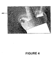
- Fig. 4 is a pictorial representation of airflow 402 surrounding the air duct 104 of the ducted fan air-vehicle 100.
- the airflow 402 is depicted as flowing from the left-hand side of the page to the right-hand side. Of course, the airflow 402 may flow in many directions with respect to the ducted fan air-vehicle 100.
- FIG. 4 there is a pressure differential at the lip 108 of the air duct 104 on the windward side 404 of the air duct 104 and the leeward side 406 of the air duct 104.
- the air data system 102 takes advantage of this pressure differential between the windward side 404 and leeward side 406 of the air duct 104 in order to provide airflow information.
- the air data system 102 may measure and calculate a plurality of pressure differentials.
- the pressure sensors 202 measure the pressure and the processor 118 of the air data system 102 calculates the plurality of pressure differentials across the air duct 104.
- the pressure sensors 202 are sensitive to the velocity of the airflow 402, and there may be a linear relationship between the differential pressure measurements and velocity of the airflow 402. This linear relationship between the pressure measurements across the air duct 104 and the velocity of the airflow 402 surrounding the air duct 104 is useful for calculating the air data.
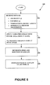
- Fig. 5 is a flow chart depicting a method 500 for air data generation by the air data system 102 of the ducted fan air-vehicle 100.
- the example depicted in Fig. 5 shows steps that may be performed by the processor 118 of the air data system 102.
- the air data system 102 may receive inputs used to determine air data. These inputs may include air density (p), fan speed (n) of the ducted fan 106, vehicle pitch angle, vehicle roll angle, and differential pressures measurements from the pairs of pressure sensors 202 across the lip 108 of the air duct 104.
- the processor 118 of the air data system 102 may receive these inputs.
- the air data system 102 may apply a calibrated linear curve fit for a pressure differential against velocity of the airflow 402.
- a calibrated linear curve fit for a pressure differential against velocity of the airflow 402.
- the pressure differential measurements may be adjusted by the other inputs received at block 502 in order to accurately determine the linear relationship between the pressure differentials across the lip 108 of the air duct 104 and the velocity of airflow 402 surrounding the air-vehicle 100. Applying the calibrated linear curve fit is further described in reference to Fig. 6 .
- the air data system 102 may determine the speed and direction of the airflow 402.
- the air data system 102 may determine the speed and direction of the airflow 402 based on the calibrated linear curve fit for a pressure differential against velocity of the airflow 402 applied at block 504. This determination is further described in reference to Fig. 6 .
- the air data system 102 may estimate the force the airflow 402 generates on the air-vehicle 100.
- the air data system 102 may estimate the force the airflow 402 generates on the air-vehicle 100 based on the calibrated linear curve fit for a pressure differential against velocity of the airflow 402 applied at block 504. This estimation is further described in reference to Fig. 6 .
- the air data system 102 may repeat the method 500 for air data generation throughout the flight of the air-vehicle 100 in order to generate air data. Alternatively, the air data system 102 may repeat the method 500 for air data generation periodically during the flight of the air-vehicle 100.
- Fig. 6 is a flow diagram 600 depicting computation data flow for applying the calibrated linear curve fit described at block 504.
- each pressure sensor input is modified by the ducted fan air-vehicle attitude.
- each pressure input is modified by a ⁇ P pitch angle in order to compensate for the pitch of the ducted fan air-vehicle.
- each pressure sensor input is modified by a ⁇ R roll angle in order to compensate for the roll attitude of the ducted fan air-vehicle.
- the relative magnitudes of pressure data may be modified by a gain multiplier factor of attitude. This compensation does a coordinate transformation between the earth axis and the vehicle axis.
- Vehicle attitude is an indicator of relative wind velocity either from desired speed or compensation for winds.
- the pitch and roll angles may be estimated from the avionics system 120 of the air-vehicle. For instance, the pitch and roll angles of the air-vehicle may be determined with a vehicle inertial sensor system.
- the air data system 102 may compute pressure differential values between pairs of pressure sensors 202.
- the pressure differentials may be calculated between a pressure sensor 202 on the windward side 404 of the air duct 104 and the pressure sensor 202 substantially 180 degrees away on the leeward side 406 of the air duct 104.
- the differential sensor pair value may be obtained by subtracting the pressure sensor input obtained at a first pressure sensor of a pair from the pressure sensor input obtained at a second pressure sensor of the pair.
- one differential measurement may be the difference between the pressure measured by pressure sensor 202 located at 0 degrees and the pressure sensor 202 located at 180 degrees.
- the differential pressure measurements are ⁇ p (135 - 315) , ⁇ p (180 - 0) , ⁇ p (225 - 45) , and ⁇ p (270 - 90) .
- pressure differentials may be calculated from pairs of sensors other than pairs with sensors directly across the duct at substantially 180 degrees. For example, a pressure differential measurement may be obtained from the 135 degree pressure sensor position and the 225 degree pressure sensor position in an eight pressure sensor configuration. Other pairs for pressure differential measurements are possible as well.
- the differential pressure sensor pair values may be compensated by the fan speed n in order to linearize the differential pressure pair values.
- the pressure differential can be normalized on fan speed by dividing the differential pressure measurements by the fan speed, ⁇ p/n.
- the air data system 102 may perform air density compensation from the air density input P C .
- the air data system 102 may apply a linear velocity curve fit for linearization of the air data in order to generate individual velocities of airflow across the air duct. Therefore, for the compensated ⁇ p (135 - 315) , ⁇ p (180 - 0) , ⁇ p (225 - 45), and ⁇ p (270 - 90), the air data system 102 may apply velocity curve fits to the pressure differentials in order to generate the individual velocities of airflow 402 across the air duct 104. In the arrangement having eight pressure sensors 202 as depicted in Fig.
- the air data system 102 generates four individual velocity vectors V N, denoted V (135 - 315) , V (180 - 0) , V (225 - 45 ), and V (270 - 90) in Fig. 6 .
- V (135 - 315) the pressure differentials have been compensated and normalized, the pressure differential vs. velocity of airflow relationship is linear, and intercept values of the linear curve fit are near zero. Therefore, the individual velocity vectors V N may be obtained from the pressure data measured by the pressure sensors 202.
- Fig. 7 shows a graph 700 illustrating a linear velocity curve fit 702 for compensated and normalized pressure data plotted against velocity, for a given vehicle pitch, with an intercept value near zero.
- the linear velocity curve fit 702 of calibrated and normalized pressure data plotted against velocity may vary for different vehicle pitch angles.
- the processor 118 may process the obtained velocity curve fits in order to generate a total velocity vector (V T ) 616 of the airflow based on the individual velocity vectors of air across the lip of the air duct.
- the processor 118 may generate V T by summing the individual velocity vectors V (135 - 315) , V (180 - 0) , V (225 - 45 ), and V (270 - 90 ). This total velocity vector includes the speed and direction of the airflow with respect to the air-vehicle 100.
- the processor 118 may process the obtained velocity curve fits in order to generate the instantaneous forces (F T ) 618 generated by the airflow 402 on the air-vehicle 100.
- the instantaneous forces 618 may be utilized by the avionics system 120 to control the air-vehicle 140.
- the forces generated by the airflow on the vehicle may be estimated from the speed and direction of airflow acting on the vehicle.
- the avionics system 120 may use the estimated forces generated by the processor 118 of the air data system 102 in order to adjust the vehicle attitude to prevent lateral translations resulting from the airflow 402 surrounding the air-vehicle 100, such as from wind gusts and wind shears.
- the speed and direction of the airflow and forces generated by the airflow 402 on the air-vehicle 100 may be used by an inner loop gust rejection control system.
- This system may tilt the air-vehicle in the direction of the wind or wind gust as calculated by the air-vehicle in anticipation of the forces being applied in order to prevent any resulting lateral translations.
- the air data system 102 may provide the air-vehicle 100 with an air data system that can accurately measure speed, direction, and the resulting displacement forces on the vehicle from cross winds, wind shears, wind gusts, and time dependent aerodynamic forces.
- the air data system 102 measures air data based on a collection of air pressure measurements across the lip of an air duct. Based on the collection of air pressure measurements the air data system calculates differential pressure between a first point on the lip of the air duct and a second point substantially 180 degrees away from the first point. Using the measurements, the air data system may operate to determine speed, direction, and the resulting displacement forces on the vehicle from airflow surrounding the air-vehicle.
- an avionics system may utilize the information provided by the air data system 102 in order to adjust vehicle attitude to prevent such lateral translations of the air-vehicle 100.
Landscapes
- Engineering & Computer Science (AREA)
- Aviation & Aerospace Engineering (AREA)
- Physics & Mathematics (AREA)
- General Physics & Mathematics (AREA)
- Mechanical Engineering (AREA)
- Indicating Or Recording The Presence, Absence, Or Direction Of Movement (AREA)
- Measuring Temperature Or Quantity Of Heat (AREA)
Applications Claiming Priority (2)
| Application Number | Priority Date | Filing Date | Title |
|---|---|---|---|
| US78662506P | 2006-03-27 | 2006-03-27 | |
| US11/685,532 US7841563B2 (en) | 2006-03-27 | 2007-03-13 | Ducted fan air data system |
Publications (3)
| Publication Number | Publication Date |
|---|---|
| EP1840578A2 EP1840578A2 (en) | 2007-10-03 |
| EP1840578A3 EP1840578A3 (en) | 2008-10-01 |
| EP1840578B1 true EP1840578B1 (en) | 2010-06-02 |
Family
ID=38180135
Family Applications (1)
| Application Number | Title | Priority Date | Filing Date |
|---|---|---|---|
| EP07104858A Not-in-force EP1840578B1 (en) | 2006-03-27 | 2007-03-26 | Ducted Fan Air Data System |
Country Status (5)
| Country | Link |
|---|---|
| US (1) | US7841563B2 (enExample) |
| EP (1) | EP1840578B1 (enExample) |
| JP (1) | JP4804393B2 (enExample) |
| KR (1) | KR20070096981A (enExample) |
| DE (1) | DE602007006853D1 (enExample) |
Families Citing this family (52)
| Publication number | Priority date | Publication date | Assignee | Title |
|---|---|---|---|---|
| US8087315B2 (en) * | 2006-10-10 | 2012-01-03 | Honeywell International Inc. | Methods and systems for attaching and detaching a payload device to and from, respectively, a gimbal system without requiring use of a mechanical tool |
| US7681832B2 (en) | 2007-05-02 | 2010-03-23 | Honeywell International Inc. | Ducted fan air vehicle with deployable wings |
| US7970532B2 (en) * | 2007-05-24 | 2011-06-28 | Honeywell International Inc. | Flight path planning to reduce detection of an unmanned aerial vehicle |
| US8251307B2 (en) * | 2007-06-11 | 2012-08-28 | Honeywell International Inc. | Airborne manipulator system |
| JP4683360B2 (ja) * | 2007-12-12 | 2011-05-18 | 清 佐直 | 円盤状飛行機 |
| WO2009091792A2 (en) * | 2008-01-15 | 2009-07-23 | Sysense, Inc. | A methodology for autonomous navigation and control of a tethered drogue |
| US8162256B2 (en) * | 2008-03-19 | 2012-04-24 | Honeywell International Inc. | Launch and capture systems for vertical take-off and landing (VTOL) vehicles |
| US8109711B2 (en) * | 2008-07-18 | 2012-02-07 | Honeywell International Inc. | Tethered autonomous air vehicle with wind turbines |
| US8123460B2 (en) * | 2008-07-23 | 2012-02-28 | Honeywell International Inc. | UAV pod cooling using integrated duct wall heat transfer |
| US8387911B2 (en) * | 2008-07-25 | 2013-03-05 | Honeywell International Inc. | Ducted fan core for use with an unmanned aerial vehicle |
| US8070103B2 (en) * | 2008-07-31 | 2011-12-06 | Honeywell International Inc. | Fuel line air trap for an unmanned aerial vehicle |
| US8240597B2 (en) | 2008-08-06 | 2012-08-14 | Honeywell International Inc. | UAV ducted fan lip shaping |
| US8070092B2 (en) * | 2008-10-31 | 2011-12-06 | Honeywell International Inc. | Noise-suppressing strut support system for an unmanned aerial vehicle |
| US8123169B2 (en) * | 2008-11-12 | 2012-02-28 | Honeywell International Inc. | Vertical non-bladdered fuel tank for a ducted fan vehicle |
| US8242623B2 (en) * | 2008-11-13 | 2012-08-14 | Honeywell International Inc. | Structural ring interconnect printed circuit board assembly for a ducted fan unmanned aerial vehicle |
| US8225822B2 (en) * | 2008-11-14 | 2012-07-24 | Honeywell International Inc. | Electric fueling system for a vehicle that requires a metered amount of fuel |
| US20110001017A1 (en) * | 2008-12-08 | 2011-01-06 | Honeywell International Inc. | Uav ducted fan swept and lean stator design |
| US8328130B2 (en) * | 2008-12-08 | 2012-12-11 | Honeywell International Inc. | Vertical take off and landing unmanned aerial vehicle airframe structure |
| US8375837B2 (en) * | 2009-01-19 | 2013-02-19 | Honeywell International Inc. | Catch and snare system for an unmanned aerial vehicle |
| US8348190B2 (en) * | 2009-01-26 | 2013-01-08 | Honeywell International Inc. | Ducted fan UAV control alternatives |
| US8205820B2 (en) * | 2009-02-03 | 2012-06-26 | Honeywell International Inc. | Transforming unmanned aerial-to-ground vehicle |
| US20110180667A1 (en) * | 2009-03-10 | 2011-07-28 | Honeywell International Inc. | Tether energy supply system |
| US8386095B2 (en) * | 2009-04-02 | 2013-02-26 | Honeywell International Inc. | Performing corrective action on unmanned aerial vehicle using one axis of three-axis magnetometer |
| US8821123B2 (en) * | 2010-03-08 | 2014-09-02 | The Penn State Research Foundation | Double-ducted fan |
| US8135503B2 (en) * | 2010-04-27 | 2012-03-13 | Honeywell International Inc. | Ground proximity sensor |
| US8820672B2 (en) * | 2012-05-07 | 2014-09-02 | Honeywell International Inc. | Environmental sampling with an unmanned aerial vehicle |
| SG2013004940A (en) * | 2013-01-21 | 2014-08-28 | Singapore Tech Aerospace Ltd | Method for improving crosswind stability of a propeller duct and a corresponding apparatus, system and computer readable medium |
| WO2014209220A1 (en) * | 2013-06-24 | 2014-12-31 | Singapore Technologies Aerospace Ltd | An unmanned aerial vehicle and a method for landing the same |
| US10184678B2 (en) | 2013-09-06 | 2019-01-22 | Carrier Corporation | System and method for measuring duct leakage in a HVAC system |
| CN104793011B (zh) * | 2014-12-19 | 2018-03-30 | 太原航空仪表有限公司 | 一种列车车载全向固态测风的方法 |
| AU2016267963B2 (en) | 2015-05-25 | 2020-08-13 | Dotterel Technologies Limited | A shroud for an aircraft |
| US10464668B2 (en) | 2015-09-02 | 2019-11-05 | Jetoptera, Inc. | Configuration for vertical take-off and landing system for aerial vehicles |
| US11001378B2 (en) | 2016-08-08 | 2021-05-11 | Jetoptera, Inc. | Configuration for vertical take-off and landing system for aerial vehicles |
| US10501197B2 (en) | 2015-09-02 | 2019-12-10 | Jetoptera, Inc. | Fluidic propulsive system |
| WO2017161304A1 (en) * | 2016-03-18 | 2017-09-21 | Sunlight Photonics Inc. | Systems, methods, and apparatus for airflow sensing and close formation flight |
| US10017271B2 (en) | 2016-03-18 | 2018-07-10 | Sunlight Photonics Inc. | Methods of three dimensional (3D) airflow sensing and analysis |
| US11175202B2 (en) | 2018-01-02 | 2021-11-16 | Arthur W Mohr, Jr. | Apparatus and method for collecting environmental samples |
| CN107161352B (zh) * | 2017-05-04 | 2023-08-18 | 安徽工程大学 | 一种浮体式四旋翼飞行机器人降落平台 |
| KR20200043980A (ko) | 2017-06-27 | 2020-04-28 | 제톱테라 잉크. | 항공 비히클용 수직 이륙 및 착륙 시스템을 위한 구성 |
| AU2018306554A1 (en) | 2017-07-24 | 2020-02-20 | Dotterel Technologies Limited | Shroud |
| US10423831B2 (en) | 2017-09-15 | 2019-09-24 | Honeywell International Inc. | Unmanned aerial vehicle based expansion joint failure detection system |
| EP3460436A1 (en) | 2017-09-22 | 2019-03-27 | Rosemount Aerospace Inc. | Low profile sensor |
| GB2558709B (en) | 2017-09-22 | 2019-02-20 | Garrood Barnaby | An airflow measurement device |
| EP3462178B1 (en) | 2017-09-22 | 2021-05-26 | Rosemount Aerospace Inc. | Low profile air data architecture |
| US11721352B2 (en) | 2018-05-16 | 2023-08-08 | Dotterel Technologies Limited | Systems and methods for audio capture |
| CN112824897B (zh) * | 2019-11-21 | 2023-05-23 | 立邦涂料(中国)有限公司 | 涂料及其组合物气味评价的方法和应用 |
| US12084181B2 (en) * | 2020-01-10 | 2024-09-10 | The Board Of Regents Of The University Of Oklahoma | Unmanned aerial system for sampling atmospheric data |
| US11851178B2 (en) * | 2020-02-14 | 2023-12-26 | The Aerospace Corporation | Long range endurance aero platform system |
| KR102164372B1 (ko) * | 2020-04-03 | 2020-10-12 | 주식회사 파블로항공 | 소형 고정익 무인항공기의 경로 추종 방법 및 이를 이용한 lgvf 경로 추종 제어기 |
| US11827344B2 (en) * | 2020-12-09 | 2023-11-28 | Textron Innovations Inc. | Low noise ducted fan |
| CN115489632B (zh) * | 2022-09-19 | 2024-09-06 | 中国铁路设计集团有限公司 | 爬壁机器人压力控制方法 |
| CN120762432B (zh) * | 2025-09-11 | 2025-12-05 | 浙江航御智控科技有限公司 | 一种基于涵道电机的无人机降落自动纠偏控制系统 |
Family Cites Families (23)
| Publication number | Priority date | Publication date | Assignee | Title |
|---|---|---|---|---|
| US3883095A (en) * | 1973-09-19 | 1975-05-13 | Nasa | Reversed cowl flap inlet thrust augmentor |
| JPH06100612B2 (ja) * | 1986-02-06 | 1994-12-12 | 日本電装株式会社 | 風向検出装置及び風向検出装置取り付け方法 |
| US4829813A (en) * | 1987-07-20 | 1989-05-16 | General Electric Company | Method and apparatus for nonintrusively determining mach number |
| US4893261A (en) * | 1987-11-20 | 1990-01-09 | United Technologies Corporation | Apparatus and method for determining airspeed and direction |
| JPH0552864A (ja) * | 1991-08-22 | 1993-03-02 | Mitsubishi Heavy Ind Ltd | 風向風速計 |
| RU2046344C1 (ru) | 1992-11-26 | 1995-10-20 | Государственный Сибирский научно-исследовательский институт авиации им. С.А.Чаплыгина | Устройство для измерения воздушной скорости сверхлегких летательных аппаратов |
| US5295643A (en) * | 1992-12-28 | 1994-03-22 | Hughes Missile Systems Company | Unmanned vertical take-off and landing, horizontal cruise, air vehicle |
| US5279155A (en) * | 1993-02-04 | 1994-01-18 | Honeywell, Inc. | Mass airflow sensor |
| JP2952397B2 (ja) * | 1994-08-23 | 1999-09-27 | 科学技術庁航空宇宙技術研究所長 | 対気飛行速度ベクトル計測装置を用いた対気能動制御航空機 |
| JP2694263B2 (ja) * | 1994-08-23 | 1997-12-24 | 科学技術庁航空宇宙技術研究所長 | 三次元気流発生装置、及び該装置を使用した航空機の飛行制御系検証方法並びに飛行モーションシミュレータ |
| US5811691A (en) * | 1997-12-26 | 1998-09-22 | Sikorsky Aircraft Corporation | Blade-mounted total pressure probe for a rotating blade |
| JPH11217099A (ja) * | 1998-01-30 | 1999-08-10 | Baitekkusu:Kk | 空中運搬機 |
| US6216064B1 (en) * | 1998-02-24 | 2001-04-10 | Alliedsignal Inc. | Method and apparatus for determining altitude |
| US6101429A (en) * | 1998-04-07 | 2000-08-08 | Tao Of Systems Integration, Inc. | Broad-range, multi-directional aircraft airspeed measuring system |
| US6134485A (en) * | 1999-02-18 | 2000-10-17 | The Boeing Company | System and method for measuring physical parameters using an integrated multisensor system |
| US6270038B1 (en) * | 1999-04-22 | 2001-08-07 | Sikorsky Aircraft Corporation | Unmanned aerial vehicle with counter-rotating ducted rotors and shrouded pusher-prop |
| US6419186B1 (en) * | 2000-03-31 | 2002-07-16 | Rosemount Aerospace Inc. | Standoff mounting for air data sensing probes on a helicopter |
| US6672152B2 (en) * | 2001-12-21 | 2004-01-06 | Honeywell International Inc. | Flush surface air data sensor |
| JP4155081B2 (ja) * | 2003-04-02 | 2008-09-24 | トヨタ自動車株式会社 | 垂直離着陸装置 |
| US7155969B2 (en) * | 2003-12-10 | 2007-01-02 | Rosemount Aerospace Inc. | System for and method of acoustic and through skin air data measurement |
| FR2864025B1 (fr) | 2003-12-23 | 2007-01-12 | Eurocopter France | Procede et dispositif pour reduire par un empennage orientable les vibrations engendrees sur le fuselage d'un helicoptere |
| FR2871136B1 (fr) | 2004-06-04 | 2006-09-15 | Bertin Technologies Soc Par Ac | Drone miniaturise a atterrissage et decollage vertical |
| US7284420B2 (en) * | 2004-07-13 | 2007-10-23 | Honeywell International Inc. | Air data system and method for rotary aircraft |
-
2007
- 2007-03-13 US US11/685,532 patent/US7841563B2/en not_active Expired - Fee Related
- 2007-03-26 DE DE602007006853T patent/DE602007006853D1/de active Active
- 2007-03-26 EP EP07104858A patent/EP1840578B1/en not_active Not-in-force
- 2007-03-27 KR KR1020070030069A patent/KR20070096981A/ko not_active Withdrawn
- 2007-03-27 JP JP2007081643A patent/JP4804393B2/ja not_active Expired - Fee Related
Also Published As
| Publication number | Publication date |
|---|---|
| EP1840578A2 (en) | 2007-10-03 |
| US7841563B2 (en) | 2010-11-30 |
| DE602007006853D1 (de) | 2010-07-15 |
| US20070221790A1 (en) | 2007-09-27 |
| KR20070096981A (ko) | 2007-10-02 |
| EP1840578A3 (en) | 2008-10-01 |
| JP2007263962A (ja) | 2007-10-11 |
| JP4804393B2 (ja) | 2011-11-02 |
Similar Documents
| Publication | Publication Date | Title |
|---|---|---|
| EP1840578B1 (en) | Ducted Fan Air Data System | |
| US6273370B1 (en) | Method and system for estimation and correction of angle-of-attack and sideslip angle from acceleration measurements | |
| Neumann et al. | Real-time wind estimation on a micro unmanned aerial vehicle using its inertial measurement unit | |
| US5423209A (en) | Truncated pyramid-shape multi-hole pitot probe and flight velocity detection system using said truncated pyramid-shape multi-hole pitot probe | |
| US6807468B2 (en) | Method for estimating wind | |
| US20120298801A1 (en) | Aircraft wing and sensor | |
| CN112683446B (zh) | 一种飞机实时重心位置估计方法 | |
| US20130145836A1 (en) | Probe for Measuring a Local Angle of Attack and Method Implementing Same | |
| Gonzalez-Rocha et al. | Measuring atmospheric winds from quadrotor motion | |
| WO1994015832A1 (en) | Aerodynamic pressure sensor systems | |
| US4702106A (en) | Method for determining the horizontal airspeed of helicopters in low speed ranges | |
| Aboelezz et al. | Wind tunnel calibration, corrections and experimental validation for fixed-wing micro air vehicles measurements | |
| Beeler et al. | Flight techniques for determining airplane drag at high Mach numbers | |
| RU2341775C1 (ru) | Способ определения аэродинамического угла летательного аппарата | |
| Colgren et al. | A proposed system architecture for estimation of angle-of-attack and sideslip angle | |
| Ariante et al. | Velocity and attitude estimation of a small unmanned aircraft with micro Pitot tube and Inertial Measurement Unit (IMU) | |
| GB2491167A (en) | Aircraft wing blister | |
| Curry et al. | Dynamic ground effect for a cranked arrow wing airplane | |
| US6938472B2 (en) | Static pressure calculation from dynamic pressure for rotary air-data system and methodology therefor | |
| Colgren et al. | Flight Test validation of sideslip estimation using inertial accelerations | |
| Foster et al. | Flight Test Validation of Tandem Propeller Performance With Vertical Offset | |
| JPH0447267B2 (enExample) | ||
| Gainutdinova et al. | Numerical and Experimental Design Parameter Analysis of VTOL Airframe Control Elements | |
| Efremova et al. | Study of Procedure Errors of the Vortex Air Data System of a Subsonic Aircraft | |
| EP2527845A1 (en) | Aircraft wing and sensor |
Legal Events
| Date | Code | Title | Description |
|---|---|---|---|
| PUAI | Public reference made under article 153(3) epc to a published international application that has entered the european phase |
Free format text: ORIGINAL CODE: 0009012 |
|
| AK | Designated contracting states |
Kind code of ref document: A2 Designated state(s): AT BE BG CH CY CZ DE DK EE ES FI FR GB GR HU IE IS IT LI LT LU LV MC MT NL PL PT RO SE SI SK TR |
|
| AX | Request for extension of the european patent |
Extension state: AL BA HR MK YU |
|
| PUAL | Search report despatched |
Free format text: ORIGINAL CODE: 0009013 |
|
| AK | Designated contracting states |
Kind code of ref document: A3 Designated state(s): AT BE BG CH CY CZ DE DK EE ES FI FR GB GR HU IE IS IT LI LT LU LV MC MT NL PL PT RO SE SI SK TR |
|
| AX | Request for extension of the european patent |
Extension state: AL BA HR MK RS |
|
| 17P | Request for examination filed |
Effective date: 20090323 |
|
| 17Q | First examination report despatched |
Effective date: 20090422 |
|
| AKX | Designation fees paid |
Designated state(s): DE FR GB |
|
| GRAP | Despatch of communication of intention to grant a patent |
Free format text: ORIGINAL CODE: EPIDOSNIGR1 |
|
| GRAS | Grant fee paid |
Free format text: ORIGINAL CODE: EPIDOSNIGR3 |
|
| GRAA | (expected) grant |
Free format text: ORIGINAL CODE: 0009210 |
|
| AK | Designated contracting states |
Kind code of ref document: B1 Designated state(s): DE FR GB |
|
| REG | Reference to a national code |
Ref country code: GB Ref legal event code: FG4D |
|
| REF | Corresponds to: |
Ref document number: 602007006853 Country of ref document: DE Date of ref document: 20100715 Kind code of ref document: P |
|
| PLBE | No opposition filed within time limit |
Free format text: ORIGINAL CODE: 0009261 |
|
| STAA | Information on the status of an ep patent application or granted ep patent |
Free format text: STATUS: NO OPPOSITION FILED WITHIN TIME LIMIT |
|
| 26N | No opposition filed |
Effective date: 20110303 |
|
| REG | Reference to a national code |
Ref country code: DE Ref legal event code: R097 Ref document number: 602007006853 Country of ref document: DE Effective date: 20110302 |
|
| REG | Reference to a national code |
Ref country code: FR Ref legal event code: PLFP Year of fee payment: 10 |
|
| PGFP | Annual fee paid to national office [announced via postgrant information from national office to epo] |
Ref country code: FR Payment date: 20160223 Year of fee payment: 10 Ref country code: GB Payment date: 20160224 Year of fee payment: 10 |
|
| PGFP | Annual fee paid to national office [announced via postgrant information from national office to epo] |
Ref country code: DE Payment date: 20160324 Year of fee payment: 10 |
|
| REG | Reference to a national code |
Ref country code: DE Ref legal event code: R119 Ref document number: 602007006853 Country of ref document: DE |
|
| GBPC | Gb: european patent ceased through non-payment of renewal fee |
Effective date: 20170326 |
|
| REG | Reference to a national code |
Ref country code: FR Ref legal event code: ST Effective date: 20171130 |
|
| PG25 | Lapsed in a contracting state [announced via postgrant information from national office to epo] |
Ref country code: FR Free format text: LAPSE BECAUSE OF NON-PAYMENT OF DUE FEES Effective date: 20170331 Ref country code: DE Free format text: LAPSE BECAUSE OF NON-PAYMENT OF DUE FEES Effective date: 20171003 |
|
| PG25 | Lapsed in a contracting state [announced via postgrant information from national office to epo] |
Ref country code: GB Free format text: LAPSE BECAUSE OF NON-PAYMENT OF DUE FEES Effective date: 20170326 |