EP1840428A1 - Relief valve - Google Patents
Relief valve Download PDFInfo
- Publication number
- EP1840428A1 EP1840428A1 EP20070105106 EP07105106A EP1840428A1 EP 1840428 A1 EP1840428 A1 EP 1840428A1 EP 20070105106 EP20070105106 EP 20070105106 EP 07105106 A EP07105106 A EP 07105106A EP 1840428 A1 EP1840428 A1 EP 1840428A1
- Authority
- EP
- European Patent Office
- Prior art keywords
- path
- valve
- guide
- discharge flow
- relief
- Prior art date
- Legal status (The legal status is an assumption and is not a legal conclusion. Google has not performed a legal analysis and makes no representation as to the accuracy of the status listed.)
- Withdrawn
Links
Images


Classifications
-
- F—MECHANICAL ENGINEERING; LIGHTING; HEATING; WEAPONS; BLASTING
- F16—ENGINEERING ELEMENTS AND UNITS; GENERAL MEASURES FOR PRODUCING AND MAINTAINING EFFECTIVE FUNCTIONING OF MACHINES OR INSTALLATIONS; THERMAL INSULATION IN GENERAL
- F16K—VALVES; TAPS; COCKS; ACTUATING-FLOATS; DEVICES FOR VENTING OR AERATING
- F16K15/00—Check valves
- F16K15/02—Check valves with guided rigid valve members
- F16K15/025—Check valves with guided rigid valve members the valve being loaded by a spring
-
- F—MECHANICAL ENGINEERING; LIGHTING; HEATING; WEAPONS; BLASTING
- F16—ENGINEERING ELEMENTS AND UNITS; GENERAL MEASURES FOR PRODUCING AND MAINTAINING EFFECTIVE FUNCTIONING OF MACHINES OR INSTALLATIONS; THERMAL INSULATION IN GENERAL
- F16K—VALVES; TAPS; COCKS; ACTUATING-FLOATS; DEVICES FOR VENTING OR AERATING
- F16K17/00—Safety valves; Equalising valves, e.g. pressure relief valves
- F16K17/02—Safety valves; Equalising valves, e.g. pressure relief valves opening on surplus pressure on one side; closing on insufficient pressure on one side
- F16K17/04—Safety valves; Equalising valves, e.g. pressure relief valves opening on surplus pressure on one side; closing on insufficient pressure on one side spring-loaded
- F16K17/0446—Safety valves; Equalising valves, e.g. pressure relief valves opening on surplus pressure on one side; closing on insufficient pressure on one side spring-loaded with an obturating member having at least a component of their opening and closing motion not perpendicular to the closing faces
- F16K17/046—Safety valves; Equalising valves, e.g. pressure relief valves opening on surplus pressure on one side; closing on insufficient pressure on one side spring-loaded with an obturating member having at least a component of their opening and closing motion not perpendicular to the closing faces the valve being of the gate valve type or the sliding valve type
-
- Y—GENERAL TAGGING OF NEW TECHNOLOGICAL DEVELOPMENTS; GENERAL TAGGING OF CROSS-SECTIONAL TECHNOLOGIES SPANNING OVER SEVERAL SECTIONS OF THE IPC; TECHNICAL SUBJECTS COVERED BY FORMER USPC CROSS-REFERENCE ART COLLECTIONS [XRACs] AND DIGESTS
- Y10—TECHNICAL SUBJECTS COVERED BY FORMER USPC
- Y10T—TECHNICAL SUBJECTS COVERED BY FORMER US CLASSIFICATION
- Y10T137/00—Fluid handling
- Y10T137/7722—Line condition change responsive valves
- Y10T137/7837—Direct response valves [i.e., check valve type]
- Y10T137/7904—Reciprocating valves
- Y10T137/7922—Spring biased
- Y10T137/7925—Piston-type valves
Definitions
- the present invention relates to a relief valve mounted on a pump such as an oil pump, for preventing pressure abnormality by allowing fluid to escape when a discharge fluid pressure reaches a predetermined set value, the relief valve also being able to prevent influx of oil sludge into the valve.
- Relief valves are mounted on pumps such as oil pumps. When the discharge oil (fluid) pressure of the pump reaches a set value the relief valve, subject to movement of a valve member, allows oil to escape though an outlet port provided in the circumferential wall of a cylinder path.
- Japanese Laid-open Utility Model Application No. S62-29487 Japanese Laid-open Utility Model Application No. S63-154709 , Japanese Laid-open Utility Model Application No. H2-24171 and Japanese Laid-open Patent Application No. 2004-293625 have been disclosed with a view to obviating this problem inherent to relief valves.
- Japanese Laid-open Utility Model Application No. S62-29487 and Japanese Laid-open Utility Model Application No. S63-154709 disclose structures in which the relief valve is arranged in a sideways-facing orientation to prevent sludge from reaching the relief valve.
- H2-24171 describes machining or the like of a cylinder hole that renders clogging caused by sludge reaching the relief valve unlikely. Furthermore, Japanese Laid-open Patent Application No. 2004-293625 describes the provision of a sludge-removing mechanism in the relief valve itself.
- the mechanism of the relief valve comprising the sludge-removal mechanism in the relief valve itself as disclosed in the Japanese Laid-open Utility Model Application No. 2004-293625 is complex and comprises a greater number of components parts. It is an object of the present invention to prevent the sludge itself from reaching the relief valve.
- a relief valve comprising a valve housing and a guide inflow path which is in the same direction as a slide direction of a valve main body that slides along a valve guide path of the valve housing under a predetermined pressure and which provides communication between a discharge flow path and the valve guide path, the valve guide path being arranged so that the relief opening part thereof is closed downwardly by the valve main body, and the valve guide path and the guide inflow path being positioned above an orthogonal cross section of the discharge flow path.
- sludge mixed with the fluid in the discharge flow path precipitates due to gravity and the sludge accumulates on the lower part in the orthogonal cross section of the discharge flow path, that is to say, the base surface thereof and, accordingly, only fluid of a state from which the sludge has been removed is able to flow from the guide inflow path into the valve guide path when the relieving operation is being performed and influx of the sludge into the relief valve can be prevented.
- valve guide path is arranged so that the relief opening part is closed downwardly by the valve main body and, in addition, the valve guide path is positioned above the guide inflow path and the orthogonal cross section of the discharge flow path, a state in which the guide inflow path and valve guide path are provided in positions above and away from the position in which the sludge mixed with the fluid precipitates and accumulates in the discharge flow path and, moreover, in which it is even more difficult for the sludge to influx into the inflow path and valve guide path is established and, accordingly, influx of the sludge into the relief valve can be even more strongly prevented.
- a sludge trap is formed in a position forward of the guide inflow path in the direction of relief flow. The sludge is thus trapped in a sludge trap and, accordingly, the influx of the sludge into the relief valve can be even more reliably prevented.
- a relief valve comprises a valve housing and a guide inflow path which is in the same direction as a slide direction of a valve main body that slides along a valve guide path of the valve housing under a predetermined pressure and which provides communication between a discharge flow path and the valve guide path, the valve guide path being arranged so that the relief opening part thereof is closed upwardly by the valve main body, the valve guide path and the guide inflow path being positioned above an orthogonal cross section of the discharge flow path, and a sludge trap being formed in the discharge flow path in a position forward of the guide inflow path in the direction of relief flow.
- the sludge mixed with the fluid flowing along the discharge flow path that accumulates due to gravity in the lower part orthogonal cross section of the discharge flow path is moved closer to the guide inflow path as a result of further flow of the fluid, the sludge falls into the sludge trap positioned forward of the guide inflow path in the direction of flow. Accordingly, the sludge can be prevented from reaching the guide inflow path and, in turn, influx of sludge into the guide inflow path and valve guide path can be prevented.
- the most common arrangement state of the valve guide path is the type that allow the valve guide path to be closed upwardly by the valve main body, and the manufacture thereof, which is based on a simple machining alone, is much simpler than provision of a normal fluid circuit.
- a relief valve comprises a valve housing and a guide inflow path which is in the same direction as a slide direction of a valve main body that slides along a valve guide path of the valve housing under a predetermined pressure and which provides communication between a discharge flow path and a relief opening part of that valve guide path, the valve guide path being arranged so that a relief opening part thereof is closed sideways by the valve main body, and a sludge trap being formed in a position forward of the guide inflow path in the direction of relief flow.
- valve guide path is arranged in a sideways direction, the range across which the relief valve is arranged can be made smaller and, in turn, a compacting of the relief valve can be achieved.
- the valve guide path may communicate with the discharge flow path by way of the guide inflow path.
- a branched discharge flow path may be formed in the discharge flow path, and the valve guide path communicates with the branched discharge flow path by way of the guide inflow path.
- abnormal pressure of the fluid is able to be more easily determined as a result of formation of a branched discharge flow path in the discharge flow path and communication of the valve guide path with the branched discharge flow path by way of the guide inflow path.
- the discharge flow path inclines upward along the direction of relief flow in the vicinity of a location for communication with the guide inflow path.
- the discharge flow path is inclined upward along the direction of relief flow in the vicinity of a location for communication with the guide inflow path, a structure in which, as the sludge mixed in the fluid is moved in a downward incline due to gravity as it precipitates, influx of the sludge into guide inflow path and valve guide path is less likely to occur can be provided.
- the branched discharge flow path may be formed in a substantially vertical direction
- a sludge trap is connectively formed in a substantially vertical direction from a lower end of the branched discharge flow path
- a guide inflow path is formed substantially horizontally between a lower end position of the branched discharge flow path and the sludge trap.
- a structure in which the sludge, due to gravity, is able to be easily trapped in the sludge trap can be provided.
- the guide inflow path is positioned in the lower end of the branched discharge flow path, that is to say, in the upper end of the sludge trap, a structure in which the guide inflow path is formed substantially horizontally and, therefore, in which influx of the sludge into the guide inflow path is unlikely, can be provided.
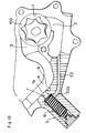
- the relief valve of the present invention is in most cases integrally formed in a pump casing of an oil pump or the like.
- the casing A is partitioned into a pump body and a pump cover.
- a rotor chamber 1 is formed in the interior of the casing A, and a rotor 100 configured from an outer rotor comprising internal teeth and an inner rotor comprising external teeth is arranged in the rotor chamber 1.
- An inflow port 2, a discharge port 3 are formed in the rotor chamber 1, and a discharge flow path 4 into which discharge fluid from the discharge port 3 is provided.
- the discharge flow path 4 leads to the exterior of the casing A.
- a branched discharge flow path 41 is formed in the discharge flow path 4, and the branched discharge flow path 41 communicates with the relief valve of the present invention.
- the relief valve of the present invention is principally configured from a valve housing 5, a valve main body 6 and a guide inflow path 7.
- a valve guide path 51 along which the valve main body 6 slides is formed in the valve housing 5, the valve main body 6 sliding along the interior thereof.
- a relief opening part 51a is formed in the valve housing 5, the relief opening part 51a functioning as an entrance for the fluid into the valve guide path 51 when the relieving operation is being performed.
- a fluid return part 52 is formed in the valve guide path 51.
- the fluid return part 52 is configured from a circuit for returning a return fluid to the inflow port 2 side when the relieving operation is being performed.
- the valve main body 6 is housed with freedom to slide in the valve guide path 51 and, at times of normal operation, that is to say, when the relieving operation is not being performed, a head part 6a of the valve main body 6 closes the relief opening part 51a and a return opening part 52a of the fluid return part 52.
- the valve main body 6 is elastically urged by a spring 8 mounted on the valve guide path 51 and normally pressed on the relief opening part 51a.
- the head part 6a of the valve main body 6 is pushed by fluid from the branched discharge flow path 41 by way of the guide inflow path 7 and caused to slide along the valve guide path 51, thereby providing communication between the relief opening part 51a and the fluid return part 52 which had been closed by the valve main body 6a of the valve main body 6 (see FIG. 2 and FIG. 7). As a result, the relieving operation is initiated.
- the means by which influx of a sludge s into the valve guide path 51 and guide inflow path 7 is prevented is based on an operation in which the sludge s mixed in a fluid Q precipitates due to gravity.
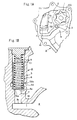
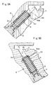
- a first embodiment thereof constitutes a structure in which the relief opening part 51a is normally positioned at the lowermost part of the valve guide path 51 and an inflow opening part 7a of the guide inflow path 7 is positioned in an upper part in the orthogonal cross section of the discharge flow path 4.
- the valve housing 5 is arranged in the casing A in such a way that the relief opening part 51a of the valve guide path 51 is normally at the lowermost part.
- valve guide path 51 The positioning of the relief opening part 51a of the valve guide path 51 in the lowermost part thereof in this way and the closure of the relief opening part 51a by the head part 6a of the valve main body 6 in a downward-orientated state in this way is referred to as a structure in which the valve guide path 51 is arranged downwardly.
- the guide direction may be set to the vertical direction as shown in FIG. 1, FIG. 2, FIG. 4 and FIG. 5, and the guide direction may be inclined as shown in FIG. 3.
- a guide direction line La of this incline of the valve guide path 51 is inclined at an angle ⁇ to a vertical axial line L.
- the range of the incline angle ⁇ excludes only the horizontal and is ⁇ 90° with respect to the vertical axial line L.
- valve guide path 51 of which the relief opening part 51a positioned in the lowermost part thereof provides communication with the guide inflow path 7 communicates with a branched discharge flow path 41 of the discharge flow path 4 by way of the guide inflow path 7 .
- the inflow opening part 7a that provides communication of the guide inflow path 7 with the branched discharge flow path 41 of the discharge flow path 4 is positioned in the upper part in the orthogonal cross section of the inner circumferential side of the branched discharge flow path 41.
- the mechanism of the first embodiment for preventing influx of the sludge s mixed in the fluid Q into the guide inflow path 7 and valve guide path 51 will be described with reference to FIG. 2.
- the relief opening part 51a of the valve guide path 51 is normally positioned in the lowermost part of the valve guide path 51.
- the inflow opening part 7a of the guide inflow path 7 is positioned in the upper part of the orthogonal cross section of the discharge flow path 4.
- the sludge s mixed in the fluid Q such as oil flowing along the branched discharge flow path 41 of the discharge flow path 4 precipitates by gravity and is trapped in the lower part (base part) of the orthogonal cross section of the discharge flow path 4 (discharge flow path 41).
- the sludge s is prevented from reaching the inflow opening part 7a and only the fluid Q in which no mixing of the sludge s has occurred flows into the valve guide path 51 from the guide inflow path 7 when the relieving operation is being performed.
- the flow of the fluid Q is described in FIG. 2 as a flow line (thick arrow line). Influx of the sludge s into the guide inflow path 7 and into guide path 51 does not occur when the relieving operation is being performed and, accordingly, influx of the sludge s into the valve guide path 51 can be prevented.
- the branched discharge flow path 41 (or discharge flow path 4) may be inclined upward along the direction of relief flow in the region in which the inflow opening part 7a that provides communication of the discharge flow path 4 with the guide inflow path 7 is formed (see FIG. 4A).
- a sludge trap 9 may be formed in a position forward of the guide inflow path 7 (see FIG. 4B) in the direction of relief flow in the branched discharge flow path 41 of the discharge flow path 4. This sludge trap 9 will be described with reference to a second embodiment.
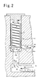
- valve housing 5 is formed in the casing A so that the relief opening part 51a of the valve guide path 51 is positioned normally in the uppermost part.
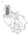
- the sludge trap 9 is formed in the branched discharge flow path 41 of the discharge flow path 4 in a forward position of the guide inflow path 7 in the direction of relief flow. That is to say, the sludge trap 9 is positioned in the upstream side in the direction of relief flow from the guide inflow path 7 (see FIG. 7).
- valve guide path 51 is arranged so that the relief opening part 51a of the valve guide path 51 is closed upwardly by the valve main body 6.
- the valve housing 5 is arranged in the casing A so that the relief opening part 51a of the valve guide path 51 is normally at the uppermost part (see FIG. 6B).
- a structure in which the relief opening part 51a of the valve guide path 51 is positioned in the uppermost part in this way and the relief opening part 51a is closed upwardly by the valve main body 6a of the valve main body 6 is referred to as a structure in which the valve guide path 51 is arranged in an upward-facing orientation.
- the guide direction of the valve guide path 51 is set in the vertical direction (see FIG. 6B), or the guide direction is inclined (See FIGS. 8A and B). Furthermore, the region of the guide inflow opening part 7a that provides communication of the discharge flow path 4 with the guide inflow path 7 may be inclined.
- the sludge trap 9 is formed in a position forward of the guide inflow path 7 in the direction of relief flow (see FIG. 9A).
- the sludge trap 9 may be formed in the discharge flow path 4 in both a forward position and a rearward position of the guide inflow path 7 in the direction of relief flow of (see FIG. 9B).
- the sludge trap 9 in both sides in the direction of relief flow, in the unlikely event of a stoppage of the operation of an apparatus such as a pump or the like resulting in backflow of the fluid Q in the direction of relief flow, the sludge s can be trapped by the sludge trap 9 and the flow of sludge s into the inflow opening part 7a can be prevented.
- the sludge trap 9 in the discharge flow path 4 in which the region of the inflow opening part 7a that provides communication with the guide inflow path 7 is inclined in both sides of the inflow opening part 7a in the direction of relief flow, even if a stoppage of the operation of an apparatus such as the pump were to occur and the fluid Q were to flow from the upward to downward side along the incline, the sludge s contained in the fluid Q can be reliably absorbed by the sludge trap 9.
- the inflow opening part 7a of the guide inflow path 7 side that provides communication between the guide inflow path 7 and discharge flow path 4 is positioned in the lower part (base part) in the orthogonal cross section of the discharge flow path 4.
- the sludge trap 9 is formed in the discharge flow path 4 in a position forward of the guide inflow path 7 in the direction of relief flow when the relieving operation of the fluid Q is being performed.
- the function of the sludge trap 9 is to prevent the sludge s mixed in the fluid Q from reaching the guide inflow path 7.
- the sludge trap 9 is formed in the lower part in the orthogonal cross section of the discharge flow path 4 or in a lower part of the branched discharge flow path 41 that branches from a part of the discharge flow path 4 as a depression or hole with a substantially circular-shaped cross section in the substantially vertical direction (see FIGS. 6C, 6D).
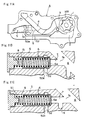
- the mechanism of the second embodiment for preventing influx of the sludge s mixed in the fluid Q into the guide inflow path 7 and valve guide path 51 will be hereinafter described with reference to FIG. 7.
- the relief opening part 51a of the valve guide path 51 is normally positioned in the uppermost part of the valve guide path 51.
- the inflow opening part 7a of the guide inflow path 7 is positioned in the lower part in the orthogonal cross section of the discharge flow path 4.
- the sludge s mixed in the fluid Q such as an oil flowing along the branched discharge flow path 41 of the discharge flow path 4 precipitates due to gravity and accumulates in the lower part in the orthogonal cross section (base part) of the discharge flow path 4.
- the sludge trap 9 is formed in the discharge flow path 4 in a position forward of the guide inflow path 7 in the direction of relief flow, the sludge s accumulated in the lower part in the orthogonal cross section of the discharge flow path 4 becomes trapped in the sludge trap 9 as a result of being squeezed and made to flow into the sludge trap 9 by the flow of the fluid Q and, accordingly, influx thereof into the guide inflow path 7 and valve guide path 51 can be prevented (see FIG. 7).
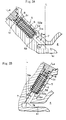
- a third embodiment will be hereinafter described with reference to FIG. 11.
- the valve guide path 51 in this third embodiment is arranged so that the relief opening part 51a of the valve guide path 51 is closed sideways by the valve main body 6.
- the sideways-facing orientation of the relief opening part 51a of the valve guide path 51 and sideways closure of the relief opening part 51a by the head part 6 of the valve main body 6a is referred to as a structure in which the valve guide path 51 is arranged in a sideways-facing orientation.
- the sludge trap 9 is formed in a forward position of the guide inflow path 7 in the direction of relief flow.
- the position in which the sludge trap 9 is formed in this third embodiment is either the discharge flow path 4 or the branched discharge flow path 41 (see FIG. 11B), or else it is formed in the guide inflow path 7 (see FIG. 11C).
- the mechanism of this third embodiment for preventing influx of the sludge s into the guide inflow path 7 and valve guide path 51 is identical to that of the second embodiment.
- FIG. 12A shows the branched discharge flow path 41 of the third embodiment provided vertically and the base part position of the branched discharge flow path 41 positioned in a lower part than the position of the inflow opening part 7a of the guide inflow path 7. This lower position than the inflow opening part 7a serves as the sludge trap 9.
- FIG. 12B shows a structure in which an inward-expanded protruding part 9a is formed between the branched discharge flow path 41 and the sludge trap 9 in which, due to the protruding part 9a, it is unlikely that the sludge s will rise upward once it has been trapped.
- FIG. 12C shows the formation of a region of the inflow opening part 7a as an inclined face that widens towards the branched discharge flow path 41 side that enhances the ease of inflow of the fluid Q.
- the relief valve is directly linked to the discharge flow path 4 main body and there is no branched discharge flow path 41 for the relieving operation formed in the discharge flow path 4.
- the relief valve is directly linked to the discharge flow path 4 main body and there is no branched discharge flow path 41 for the relieving operation formed in the discharge flow path 4.
- the relief valve is directly linked to the discharge flow path 4 in the absence of the formation of the branched discharge flow path 41.
- the discharge flow path 41 may be formed in the discharge flow path 4 with the relief valve linked to the discharge flow path 41.
Landscapes
- Engineering & Computer Science (AREA)
- General Engineering & Computer Science (AREA)
- Mechanical Engineering (AREA)
- Safety Valves (AREA)
- Details Of Valves (AREA)
- Details And Applications Of Rotary Liquid Pumps (AREA)
Applications Claiming Priority (1)
| Application Number | Priority Date | Filing Date | Title |
|---|---|---|---|
| JP2006096077A JP4426542B2 (ja) | 2006-03-30 | 2006-03-30 | リリーフバルブ |
Publications (1)
| Publication Number | Publication Date |
|---|---|
| EP1840428A1 true EP1840428A1 (en) | 2007-10-03 |
Family
ID=38224135
Family Applications (1)
| Application Number | Title | Priority Date | Filing Date |
|---|---|---|---|
| EP20070105106 Withdrawn EP1840428A1 (en) | 2006-03-30 | 2007-03-28 | Relief valve |
Country Status (4)
| Country | Link |
|---|---|
| US (1) | US20070246103A1 (enExample) |
| EP (1) | EP1840428A1 (enExample) |
| JP (1) | JP4426542B2 (enExample) |
| CN (1) | CN101046197A (enExample) |
Cited By (1)
| Publication number | Priority date | Publication date | Assignee | Title |
|---|---|---|---|---|
| FR2965034A1 (fr) * | 2010-09-16 | 2012-03-23 | Peugeot Citroen Automobiles Sa | Dispositif hydraulique pour systeme de transmission de vehicule |
Families Citing this family (8)
| Publication number | Priority date | Publication date | Assignee | Title |
|---|---|---|---|---|
| JP2012017801A (ja) * | 2010-07-07 | 2012-01-26 | Aisin Seiki Co Ltd | リリーフバルブ |
| CN104033634B (zh) * | 2013-03-05 | 2018-07-20 | 罗伯特·博世有限公司 | 溢流阀以及包括该溢流阀的低压输油泵 |
| JP6432440B2 (ja) | 2015-05-15 | 2018-12-05 | 株式会社デンソー | 高圧ポンプ |
| CN105202236B (zh) * | 2015-09-30 | 2018-04-24 | 中国石油辽河油田曙光采油厂 | 高温潜油电泵安全阀 |
| KR102613583B1 (ko) * | 2016-12-30 | 2023-12-14 | 명화공업주식회사 | 가변 오일 펌프 |
| JP7021964B2 (ja) * | 2018-01-31 | 2022-02-17 | Kyb株式会社 | 弁装置 |
| DE102020207381A1 (de) | 2020-06-15 | 2021-12-16 | Mahle International Gmbh | Ventileinrichtung sowie Brennkraftmaschine mit Ventileinrichtung |
| CN112939345B (zh) * | 2021-01-29 | 2022-05-20 | 重庆工商大学 | 智能化污水处理装置及方法 |
Citations (6)
| Publication number | Priority date | Publication date | Assignee | Title |
|---|---|---|---|---|
| JPS5824665A (ja) * | 1982-07-14 | 1983-02-14 | Sumitomo Rubber Ind Ltd | タイヤ加硫機のガス抜き装置用バルブ |
| DE3443518C1 (de) * | 1984-11-29 | 1985-12-12 | Dr.Ing.H.C. F. Porsche Ag, 7000 Stuttgart | Druckbegrenzungsventil |
| JPS61192978A (ja) * | 1985-02-21 | 1986-08-27 | Honda Motor Co Ltd | リリ−フ弁 |
| EP0212981A2 (en) * | 1985-08-21 | 1987-03-04 | Honda Giken Kogyo Kabushiki Kaisha | Oil supply system for a valve operating mechanism in internal combustion engines |
| US6116272A (en) * | 1999-03-26 | 2000-09-12 | Daimlerchrysler Coroporation | Debris resistant oil pressure relief valve |
| JP2004293625A (ja) | 2003-03-26 | 2004-10-21 | Toyota Industries Corp | 弁装置及びその異物除去方法 |
Family Cites Families (5)
| Publication number | Priority date | Publication date | Assignee | Title |
|---|---|---|---|---|
| US3310063A (en) * | 1964-06-05 | 1967-03-21 | Edwards Rivers Edwin | Washing machine dump valve |
| US4194518A (en) * | 1978-09-13 | 1980-03-25 | Nissan Motor Company, Limited | Governor having ability of removing dust from working fluid in automatic transmission |
| JP3643311B2 (ja) * | 2000-03-03 | 2005-04-27 | 本田技研工業株式会社 | リリーフ弁構造 |
| JP4328184B2 (ja) * | 2003-11-17 | 2009-09-09 | 株式会社日立製作所 | オイルポンプ |
| US20060185737A1 (en) * | 2005-01-24 | 2006-08-24 | Matthew Williamson | Pressure relief valve with debris trap |
-
2006
- 2006-03-30 JP JP2006096077A patent/JP4426542B2/ja not_active Expired - Fee Related
-
2007
- 2007-03-28 US US11/727,879 patent/US20070246103A1/en not_active Abandoned
- 2007-03-28 EP EP20070105106 patent/EP1840428A1/en not_active Withdrawn
- 2007-03-30 CN CNA2007100919745A patent/CN101046197A/zh active Pending
Patent Citations (6)
| Publication number | Priority date | Publication date | Assignee | Title |
|---|---|---|---|---|
| JPS5824665A (ja) * | 1982-07-14 | 1983-02-14 | Sumitomo Rubber Ind Ltd | タイヤ加硫機のガス抜き装置用バルブ |
| DE3443518C1 (de) * | 1984-11-29 | 1985-12-12 | Dr.Ing.H.C. F. Porsche Ag, 7000 Stuttgart | Druckbegrenzungsventil |
| JPS61192978A (ja) * | 1985-02-21 | 1986-08-27 | Honda Motor Co Ltd | リリ−フ弁 |
| EP0212981A2 (en) * | 1985-08-21 | 1987-03-04 | Honda Giken Kogyo Kabushiki Kaisha | Oil supply system for a valve operating mechanism in internal combustion engines |
| US6116272A (en) * | 1999-03-26 | 2000-09-12 | Daimlerchrysler Coroporation | Debris resistant oil pressure relief valve |
| JP2004293625A (ja) | 2003-03-26 | 2004-10-21 | Toyota Industries Corp | 弁装置及びその異物除去方法 |
Cited By (1)
| Publication number | Priority date | Publication date | Assignee | Title |
|---|---|---|---|---|
| FR2965034A1 (fr) * | 2010-09-16 | 2012-03-23 | Peugeot Citroen Automobiles Sa | Dispositif hydraulique pour systeme de transmission de vehicule |
Also Published As
| Publication number | Publication date |
|---|---|
| JP4426542B2 (ja) | 2010-03-03 |
| JP2007270927A (ja) | 2007-10-18 |
| CN101046197A (zh) | 2007-10-03 |
| US20070246103A1 (en) | 2007-10-25 |
Similar Documents
| Publication | Publication Date | Title |
|---|---|---|
| EP1840428A1 (en) | Relief valve | |
| US7875171B2 (en) | Suction filter for an automatic transmission | |
| JP5693601B2 (ja) | 組込み式の圧力制限弁を備えたスクリュースピンドルポンプ | |
| JP6412947B2 (ja) | ストレーナ装置 | |
| US20090308471A1 (en) | Startup bypass system for a screw compressor | |
| JP2003194246A (ja) | 油圧リリーフ弁 | |
| US6309198B1 (en) | Scroll compressor with improved oil flow | |
| US8057193B2 (en) | Screw compressor comprising a relief valve | |
| EP1913293A1 (en) | Pressure relief valve | |
| KR20210122050A (ko) | 펌프의 피봇 핀에 통합된 패닉 밸브 | |
| EP3267038B1 (en) | Hydraulic pump and respective multifunction valve | |
| US20190170141A1 (en) | Vacuum pump | |
| KR950009938A (ko) | 기어펌프 | |
| US20060185737A1 (en) | Pressure relief valve with debris trap | |
| CN108386701B (zh) | 一种限压阀柱塞及防卡滞的机油泵限压阀 | |
| JP2006009580A (ja) | ベーンポンプ | |
| JP2006046409A (ja) | 逆止弁 | |
| JP2009150315A (ja) | ポンプユニット | |
| JP3563139B2 (ja) | ガス放出防止器 | |
| CN120819526B (zh) | 潜油泵及其防反转防卡死保护装置 | |
| JP7625260B2 (ja) | リリーフバルブ | |
| KR102806186B1 (ko) | 변속기 유압공급장치 | |
| KR20060072284A (ko) | 캐비테이션 방지를 위한 오일필터장치 | |
| JP2023128330A (ja) | ポンプ装置 | |
| US11619223B2 (en) | Metering pump having an integrated overflow valve, and valve insert for a metering pump |
Legal Events
| Date | Code | Title | Description |
|---|---|---|---|
| PUAI | Public reference made under article 153(3) epc to a published international application that has entered the european phase |
Free format text: ORIGINAL CODE: 0009012 |
|
| AK | Designated contracting states |
Kind code of ref document: A1 Designated state(s): AT BE BG CH CY CZ DE DK EE ES FI FR GB GR HU IE IS IT LI LT LU LV MC MT NL PL PT RO SE SI SK TR |
|
| AX | Request for extension of the european patent |
Extension state: AL BA HR MK YU |
|
| RIN1 | Information on inventor provided before grant (corrected) |
Inventor name: ONO, YASUNORI Inventor name: UMEZAWA, YOSHIRO Inventor name: ENZAKA, KAZUO |
|
| 17P | Request for examination filed |
Effective date: 20080318 |
|
| AKX | Designation fees paid |
Designated state(s): DE ES FR GB IT |
|
| 17Q | First examination report despatched |
Effective date: 20100223 |
|
| STAA | Information on the status of an ep patent application or granted ep patent |
Free format text: STATUS: THE APPLICATION IS DEEMED TO BE WITHDRAWN |
|
| 18D | Application deemed to be withdrawn |
Effective date: 20100706 |