EP1840352A2 - Système d'alimentation d'air frais et méthode d'opération pour un moteur à piston - Google Patents
Système d'alimentation d'air frais et méthode d'opération pour un moteur à piston Download PDFInfo
- Publication number
- EP1840352A2 EP1840352A2 EP07104114A EP07104114A EP1840352A2 EP 1840352 A2 EP1840352 A2 EP 1840352A2 EP 07104114 A EP07104114 A EP 07104114A EP 07104114 A EP07104114 A EP 07104114A EP 1840352 A2 EP1840352 A2 EP 1840352A2
- Authority
- EP
- European Patent Office
- Prior art keywords
- valve
- piston engine
- fresh gas
- inlet
- closing
- Prior art date
- Legal status (The legal status is an assumption and is not a legal conclusion. Google has not performed a legal analysis and makes no representation as to the accuracy of the status listed.)
- Granted
Links
Images
Classifications
-
- F—MECHANICAL ENGINEERING; LIGHTING; HEATING; WEAPONS; BLASTING
- F02—COMBUSTION ENGINES; HOT-GAS OR COMBUSTION-PRODUCT ENGINE PLANTS
- F02B—INTERNAL-COMBUSTION PISTON ENGINES; COMBUSTION ENGINES IN GENERAL
- F02B29/00—Engines characterised by provision for charging or scavenging not provided for in groups F02B25/00, F02B27/00 or F02B33/00 - F02B39/00; Details thereof
- F02B29/08—Modifying distribution valve timing for charging purposes
- F02B29/083—Cyclically operated valves disposed upstream of the cylinder intake valve, controlled by external means
-
- F—MECHANICAL ENGINEERING; LIGHTING; HEATING; WEAPONS; BLASTING
- F02—COMBUSTION ENGINES; HOT-GAS OR COMBUSTION-PRODUCT ENGINE PLANTS
- F02B—INTERNAL-COMBUSTION PISTON ENGINES; COMBUSTION ENGINES IN GENERAL
- F02B75/00—Other engines
- F02B75/12—Other methods of operation
- F02B2075/125—Direct injection in the combustion chamber for spark ignition engines, i.e. not in pre-combustion chamber
-
- F—MECHANICAL ENGINEERING; LIGHTING; HEATING; WEAPONS; BLASTING
- F02—COMBUSTION ENGINES; HOT-GAS OR COMBUSTION-PRODUCT ENGINE PLANTS
- F02D—CONTROLLING COMBUSTION ENGINES
- F02D41/00—Electrical control of supply of combustible mixture or its constituents
- F02D41/30—Controlling fuel injection
- F02D41/38—Controlling fuel injection of the high pressure type
- F02D41/40—Controlling fuel injection of the high pressure type with means for controlling injection timing or duration
- F02D41/402—Multiple injections
-
- Y—GENERAL TAGGING OF NEW TECHNOLOGICAL DEVELOPMENTS; GENERAL TAGGING OF CROSS-SECTIONAL TECHNOLOGIES SPANNING OVER SEVERAL SECTIONS OF THE IPC; TECHNICAL SUBJECTS COVERED BY FORMER USPC CROSS-REFERENCE ART COLLECTIONS [XRACs] AND DIGESTS
- Y02—TECHNOLOGIES OR APPLICATIONS FOR MITIGATION OR ADAPTATION AGAINST CLIMATE CHANGE
- Y02T—CLIMATE CHANGE MITIGATION TECHNOLOGIES RELATED TO TRANSPORTATION
- Y02T10/00—Road transport of goods or passengers
- Y02T10/10—Internal combustion engine [ICE] based vehicles
- Y02T10/12—Improving ICE efficiencies
Definitions
- the present invention relates to a fresh gas system for a piston engine, in particular in a motor vehicle, having the features of the preamble of claim 1.
- the invention also relates to an operating method for a piston engine equipped with such a fresh gas system.
- a fresh gas system for a piston engine which is equipped with a manifold for supplying several individual lines with fresh gas.
- Each individual line supplies a combustion chamber of the piston engine with fresh gas, wherein each cylinder of the piston engine is associated with an inlet valve for opening and closing a connection between the associated combustion chamber and the associated individual line.
- an additional valve is arranged in each individual line upstream of the inlet valve, with which the respective individual line can be opened and closed.
- the fresh gas supply of the combustion chambers can be influenced with the aid of the additional valves so that a temperature increase in the respective cylinder which exceeds the adiabatic compression end temperature.
- This method of operation of the reciprocating engine may also be referred to as a heat load.
- the de-throttled or throttle-free fresh gas system is characterized by the lack of a throttle valve, which is located in a conventional fresh gas system in the manifold to throttle the fresh gas supply of the combustion chambers in the partial load operation of the piston engine depending on the current load condition of the piston engine.
- the throttled supply of fresh gas is problematic because considerable charge exchange losses occur and because the concomitant reduced flow rates impede mixture formation. This suffers from the quality of the combustion process and leads to comparatively poor emission values and increased fuel consumption values.
- a throttle-free or de-throttled fresh gas supply the quality of the combustion process can be significantly improved, resulting in reduced emissions and fuel consumption.
- the known piston engine operates with an electromagnetic valve control, which allows the intake valves to open arbitrarily and close.
- electromagnetic valve controls are significantly more expensive than conventional camshaft controlled valve trains.
- the present invention addresses the problem of providing a fresh gas system of the type mentioned above and an operating method of the type mentioned an improved embodiment, which allows for the piston engine reduced fuel consumption and is relatively inexpensive to implement.
- the invention is based on the general idea to realize the fresh gas quantity control in a de-throttled fresh gas system with the aid of arranged in the individual lines additional valves in which the respective additional valve is temporarily closed within an inlet time window of the respective intake valve.
- the fresh gas quantity or fresh gas charge required for the respective load state of the piston engine can be set in a targeted manner.
- the subdivision of the fresh gas load in two loading phases, of which the first ends with the closing of the additional valve, while the second begins with the reopening of the additional valve.
- the first loading phase as it were, there is a basic load of the respective combustion chamber, which for example can advantageously be used for mixture formation.
- a desired flow state for example swirl flow and / or tumble flow, can be generated in the combustion chamber relatively promptly at the ignition time, which is of decisive importance with regard to pollutant emission and efficiency of the combustion process.
- a piston engine 1 comprises an engine block 2, a fresh gas system 3, which supplies the engine block 2 fresh gas, and an exhaust system 4, the exhaust gas from the engine block 2 dissipates.
- the piston engine 1 is preferably arranged in a motor vehicle.
- the engine block 2 contains a plurality of cylinders 5, in the example four cylinders 5 are shown without limiting the generality.
- Each cylinder 5 encloses a combustion chamber 6 and leads in a known manner in each case a piston, not shown.
- Each cylinder 5 is assigned at least one inlet valve 7 and at least one outlet valve 8.
- the intake valves 7 are configured and arranged such that they can open and close the communicating connection between the respective individual pipe 11 and the respective combustion chamber 6 in the usual way.
- An associated valve control is not shown.
- the gas exchange valves 7, 8 may be controlled in a conventional manner by means of camshafts, which is relatively inexpensive to implement. It is also possible to provide an electromagnetic valve control.
- each cylinder 5 is associated with a fuel injector 9, which can inject fuel into the respective combustion chamber 6 with appropriate control.
- the fresh gas system 3 comprises at least one collecting line 10, which is communicatively connected to a plurality of individual lines 11, wherein each individual line 11 leads to one of the combustion chambers 6.
- the manifold 10 and the individual lines 11 are connected to one another via a fresh gas distributor 12.
- the individual lines 11 may also be connected directly to the manifold 10.
- Each manifold 11 includes an additional valve 13, which is designed so that it can open and close the associated individual line 11.
- a controller 14 is provided.
- This controller 14 has access to signals or general information that allows it to determine the current load condition of the piston engine 1.
- the term "load state" includes in particular the current load and power output and the current speed of the piston engine 1.
- the controller 14 is connected to an engine control unit, not shown here.
- the controller 14 may be integrated into such a motor control device in terms of hardware or implemented by software.
- the controller 14 may also preferably operate the fuel injectors 9.
- the exhaust system 4 comprises usually not specified individual lines, so-called manifold, which are connected here via an exhaust manifold to a common exhaust pipe.
- the fresh gas system 3 of the piston engine 1 is de-throttled. This means that in the fresh gas system 3 at least upstream of the additional valves 13 no means for throttling the fresh gas supply of the individual combustion chambers 6 is included.
- the piston engine 1 basically for safety reasons, eg for emergency running properties, have a throttle device, but in normal operation no Has throttle function in the conventional sense.
- the fresh gas system 3 contains no throttle valve in its collecting line 3.
- the piping system of the fresh gas system 3 is substantially ambient pressure, possibly throttled by an air filter, or the suction pressure generated by the intake of the individual cylinders 5 during an intake stroke of the associated piston, if this from the additional valves 13 in the rest of the system Fresh gas system 3 is allowed through.
- the low negative pressure which may be due to said slight throttling, is significantly lower in absolute terms than a negative pressure which prevails in a conventional throttle valve system.
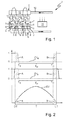
- FIG. 2 shows on the abscissa an example of a section of a piston stroke, namely an intake stroke, which starts at top dead center OT of the respective piston and ends at bottom dead center UT of the piston.
- the gradients of the inlet valve 7 and the additional valve 13 at the respective combustion chamber 6 are plotted against each other on the ordinate as a function of the intake stroke of the respective piston.
- the course of the inlet valve 7 is denoted by EV.
- For the additional valve 13 two different variants of the course are shown, which are designated ZV I and ZV II .
- the closed auxiliary valve 13 is represented in the diagram in each case by a zero line, while the opened additional valve 13 is represented in each case by a one-line.
- the additional valves 13 thus have only two during operation Switching states "OPEN” and "CLOSE” on, which differentiates the additional valves 13 of throttle valves.
- the controller 14 is designed so that it can control the additional valves 13 for implementing an operating method for the piston engine 1, which will be explained in more detail below.
- each piston cyclically performs an intake stroke which starts at top dead center TDC and ends at bottom dead center TDC.
- the associated inlet valve 7 is coupled to the piston movement, for example via a camshaft control.
- the respective intake valve 7 has an intake time window T, which is indicated in Fig. 2 by a curly bracket.
- the intake time window T is limited at its start by opening the intake valve 7 and at its end by closing the intake valve 7. Without restricting the generality takes place in the present case, the opening of the intake valve 7 at top dead center OT of the piston stroke, while the closing of the intake valve 7 takes place in the bottom dead center UT of the piston.
- the inlet time window T thus coincides with the intake stroke of the respective piston.
- the course of the opening or closing movement of the inlet valve 7 is represented in FIG. 2 by the curve EV.
- the respective combustion chamber 6 During the intake stroke of the piston, the respective combustion chamber 6 must be loaded with fresh gas.
- the amount of fresh gas or the fresh gas loading, which is to be introduced into the combustion chamber 6, depends on the current load condition of the piston engine 1.
- the invention proposes to subdivide the fresh gas charge into two charge phases during a partial load operation of the piston engine 1, where in FIG. 2 a chronologically preceding first charge phase is denoted by A, while a second charge phase subsequent to time is designated B.
- A a chronologically preceding first charge phase
- B a second charge phase subsequent to time
- the respective additional valve 13 is closed when the intake valve 7 is open, ie within the intake time window T at a closing time T S and only opened again at a later opening time T O , wherein the opening time T O is still within the Inlet window T is located.
- Both the closing time T S and the opening time T O depend on the current load condition, ie also on the rotational speed of the piston engine 1.
- the first loading phase A thus begins with the opening of the intake valve 7, ie here at the top dead center TDC and ends with the closing of the additional valve 13, ie at the closing time T S.
- the second loading phase B begins with the opening of the additional valve 13, ie at the opening time T O and ends with the closing of the inlet valve 7, ie here at the bottom dead center UT.
- a time interval between the loading phases A, B is also referred to below as the loading interval T P.
- the loading break T P thus depends on the current load condition, including speed, of the piston engine 1 from.
- the smallest engine load is in idling mode.
- idle mode the distances between the opening of the intake valve 7 and the closing of the additional valve 13 on the one hand and the opening of the additional valve 13 and the closing of the intake valve 7 on the other hand, minimal.
- the load pause T P during idling operation is maximum.
- the loading phases A, B therefore have their shortest duration in idle mode.
- the individual combustion processes require more fresh gas, so that with increasing engine load at least one or both loading phases A, B are larger in time, while the loading interval T P is smaller.
- the closing time T S and / or the opening time T O are thus shifted to early.
- both loading phases A, B can thus be increased by shifting the times T S , T O. Or only one of the loading phases A, B is increased by shifting one of the times T S , T O. It is noteworthy for the partial load operation of the piston engine 1 with entschrosselter fresh gas system 3, that adjust even with the very short loading phases A, B advantageous flow conditions. In full-load operation, the de-throttled fresh gas system 3 is particularly advantageous because it allows sufficient fresh gas loading even with short inlet time windows T.
- the controller 14 preferably controls the respective additional valve 13 so that it is necessary for the realization of first loading phase A when opening the respective inlet valve 7 is already open. This can be realized according to the course ZV I , that the additional valve 13 is opened immediately before the opening of the intake valve 7.
- controller 14 can control the additional valves 13 such that they are still open for realizing the second loading phase B when closing the respective inlet valve 7. During course ZV I , this is achieved in that the additional valve 13 closes only immediately after closing the intake valve 7.
- the respective additional valve 13 is controlled by the controller 14 so that it remains open between two inlet time windows T. That is, the respective additional valve 13 remains open after opening at the opening time T O , to which the second loading phase B begins, until it closes in the next inlet time window T at the closing time T S and thereby terminates the first loading phase A of this new inlet time window T.
- This variant comes with significantly fewer switching operations for the respective additional valve 13, which is advantageous in terms of the durability of the additional valves 13, their energy requirements and for the computer power of the controller 14th
- the controller 14 controls the respective additional valve 13 to realize the first loading phase A so that it is still closed when opening the respective inlet valve 7, so that the additional valve 13 is opened only within the inlet time window T. Additionally or alternatively, the controller 14 may also be configured so that it actuates the respective additional valve 13 for the realization of the second loading phase B within the inlet time window T to close, so that the respective additional valve 13 is already closed when closing the respective inlet valve 7. This embodiment may be advantageous with respect to certain loading operations.
- the load interval Tp may amount to at least 20% or at least 30% or at least 40% or at least 50% of the time period of the inlet time window T during partial load operation of the piston engine 1.
- the respective additional valve 13 can be permanently opened in the simplest case, so that the supplied fresh gas quantity is controlled exclusively by the respective inlet valve 7.
- a synchronization of the additional valves 13 with the associated inlet valve 7 is possible, so that they open and close at the same time.
- the fresh gas flow can be optimized for loading the respective combustion chamber 6.
- the controller 14 may be configured and coupled to the fuel injectors 9 so that they realized during the intake time window T in the respective combustion chamber 6 two injection events separated in time. For example, a first injection quantity can be injected during the first loading phase A or between the two loading phases A, B, while a second injection quantity within the second loading phase B is injected separately from it. Due to its long residence time within the combustion chamber 6, the first injection quantity can be mixed comparatively well with the fresh gas. The second injection facilitates the ignitability of the entire combustion chamber filling and thereby stabilizes the engine operation even at low load.
- the second loading phase B is important for achieving an optimized combustion process, since a desired flow situation in the combustion chamber 6 can be generated by the late and thus close to the ignition fresh gas filling, which is still substantially present at the ignition. For example, a swirl flow and / or a Tumbleströmung can be generated.
Landscapes
- Engineering & Computer Science (AREA)
- Chemical & Material Sciences (AREA)
- Combustion & Propulsion (AREA)
- Mechanical Engineering (AREA)
- General Engineering & Computer Science (AREA)
- Output Control And Ontrol Of Special Type Engine (AREA)
- Electrical Control Of Air Or Fuel Supplied To Internal-Combustion Engine (AREA)
Applications Claiming Priority (1)
| Application Number | Priority Date | Filing Date | Title |
|---|---|---|---|
| DE102006015589A DE102006015589A1 (de) | 2006-03-31 | 2006-03-31 | Frischgasanlage und Betriebsverfahren für einen Kolbenmotor |
Publications (3)
| Publication Number | Publication Date |
|---|---|
| EP1840352A2 true EP1840352A2 (fr) | 2007-10-03 |
| EP1840352A3 EP1840352A3 (fr) | 2010-03-31 |
| EP1840352B1 EP1840352B1 (fr) | 2011-12-14 |
Family
ID=38038908
Family Applications (1)
| Application Number | Title | Priority Date | Filing Date |
|---|---|---|---|
| EP07104114A Not-in-force EP1840352B1 (fr) | 2006-03-31 | 2007-03-14 | Système d'alimentation d'air frais et méthode d'opération pour un moteur à piston |
Country Status (3)
| Country | Link |
|---|---|
| US (1) | US7418945B2 (fr) |
| EP (1) | EP1840352B1 (fr) |
| DE (1) | DE102006015589A1 (fr) |
Cited By (2)
| Publication number | Priority date | Publication date | Assignee | Title |
|---|---|---|---|---|
| DE102010061859A1 (de) * | 2010-11-24 | 2012-05-24 | Mahle International Gmbh | Betriebsverfahren |
| DE102010061858A1 (de) * | 2010-11-24 | 2012-05-24 | Mahle International Gmbh | Betriebsverfahren |
Families Citing this family (2)
| Publication number | Priority date | Publication date | Assignee | Title |
|---|---|---|---|---|
| DE102009036192A1 (de) * | 2009-08-05 | 2011-02-17 | Mahle International Gmbh | Verschlusseinrichtung und Betriebsverfahren |
| DE102015214616B4 (de) * | 2015-07-31 | 2018-08-23 | Ford Global Technologies, Llc | Verfahren zum Betreiben einer abgasturboaufgeladenen Brennkraftmaschine mit Teilabschaltung |
Citations (10)
| Publication number | Priority date | Publication date | Assignee | Title |
|---|---|---|---|---|
| DE3737824A1 (de) * | 1987-11-06 | 1989-05-18 | Schatz Oskar | Verfahren zum betrieb eines verbrennungsmotors der kolbenbauart |
| EP0547566A1 (fr) * | 1991-12-16 | 1993-06-23 | Oskar Dr.-Ing. Schatz | Procédé pour contrôler l'admission d'air dans la chambre de combustion d'un moteur à combustion interne de type des pistons en deux phases |
| DE4308931A1 (de) * | 1993-03-19 | 1994-09-22 | Schatz Oskar | Verfahren und Vorrichtung zum Aufladen einer Brennkraftmaschine der Kolbenbauart |
| DE10032669A1 (de) * | 2000-07-05 | 2002-01-24 | Daimler Chrysler Ag | Verfahren und Vorrichtung zur ungedrosselten Laststeuerung einer fremdgezündeten Brennkraftmaschine |
| DE10220076A1 (de) * | 2002-05-04 | 2003-11-13 | Bosch Gmbh Robert | Verfahren und Vorrichtung zur Steuerung einer Brennkraftmaschine |
| DE10240913A1 (de) * | 2002-09-04 | 2004-03-18 | Schatz Thermo Engineering | Verbrennungsmotor der Kolbenbauart und Verfahren zu seinem Betrieb |
| WO2004055345A1 (fr) * | 2002-12-16 | 2004-07-01 | Siemens Aktiengesellschaft | Procede pour commander un changement de fonctionnement dans un moteur a combustion interne |
| US20040159721A1 (en) * | 1998-06-22 | 2004-08-19 | Hitachi, Ltd. | Cylinder injection type internal combustion engine, control method for internal combustion engine, and fuel injection valve |
| WO2005035955A1 (fr) * | 2003-10-06 | 2005-04-21 | Fev Motorentechnik Gmbh | Suralimentation par impulsions |
| DE102006028280A1 (de) * | 2006-06-20 | 2007-12-27 | Dr.Ing.H.C. F. Porsche Ag | Verfahren zur Laststeuerung einer Kolben-Brennkraftmaschine |
Family Cites Families (6)
| Publication number | Priority date | Publication date | Assignee | Title |
|---|---|---|---|---|
| US4509327A (en) * | 1983-01-27 | 1985-04-09 | Johnson Matthey, Inc. | Regenerating catalytic particulate filters and apparatus therefor |
| US4617896A (en) * | 1985-03-14 | 1986-10-21 | Yamaha Hatsudoki Kabushiki Kaisha | Internal combustion engine having three intake valves per cylinder |
| DE4141481C2 (de) * | 1991-12-16 | 2002-04-11 | Oskar Schatz | Verfahren zur Regelung des Luft-Kraftstoff-Verhältnisses eines Verbrennungsmotors, insbesondere eines Verbrennungsmotors der Kolbenbauart |
| DE19754287A1 (de) * | 1997-12-08 | 1999-06-10 | Bosch Gmbh Robert | Brennkraftmaschine |
| DE10252208A1 (de) * | 2002-11-09 | 2004-05-27 | Mahle Ventiltrieb Gmbh | Kolbenmaschine, insbesondere Hubkolbenverbrennungsmotor mit zusätzlicher Ladungssteuerung |
| DE10309730B4 (de) * | 2003-03-06 | 2012-02-16 | Mahle Filtersysteme Gmbh | Verfahren zur Impulsaufladung einer Brennkraftmaschine |
-
2006
- 2006-03-31 DE DE102006015589A patent/DE102006015589A1/de not_active Withdrawn
-
2007
- 2007-03-14 EP EP07104114A patent/EP1840352B1/fr not_active Not-in-force
- 2007-03-26 US US11/728,451 patent/US7418945B2/en not_active Expired - Fee Related
Patent Citations (10)
| Publication number | Priority date | Publication date | Assignee | Title |
|---|---|---|---|---|
| DE3737824A1 (de) * | 1987-11-06 | 1989-05-18 | Schatz Oskar | Verfahren zum betrieb eines verbrennungsmotors der kolbenbauart |
| EP0547566A1 (fr) * | 1991-12-16 | 1993-06-23 | Oskar Dr.-Ing. Schatz | Procédé pour contrôler l'admission d'air dans la chambre de combustion d'un moteur à combustion interne de type des pistons en deux phases |
| DE4308931A1 (de) * | 1993-03-19 | 1994-09-22 | Schatz Oskar | Verfahren und Vorrichtung zum Aufladen einer Brennkraftmaschine der Kolbenbauart |
| US20040159721A1 (en) * | 1998-06-22 | 2004-08-19 | Hitachi, Ltd. | Cylinder injection type internal combustion engine, control method for internal combustion engine, and fuel injection valve |
| DE10032669A1 (de) * | 2000-07-05 | 2002-01-24 | Daimler Chrysler Ag | Verfahren und Vorrichtung zur ungedrosselten Laststeuerung einer fremdgezündeten Brennkraftmaschine |
| DE10220076A1 (de) * | 2002-05-04 | 2003-11-13 | Bosch Gmbh Robert | Verfahren und Vorrichtung zur Steuerung einer Brennkraftmaschine |
| DE10240913A1 (de) * | 2002-09-04 | 2004-03-18 | Schatz Thermo Engineering | Verbrennungsmotor der Kolbenbauart und Verfahren zu seinem Betrieb |
| WO2004055345A1 (fr) * | 2002-12-16 | 2004-07-01 | Siemens Aktiengesellschaft | Procede pour commander un changement de fonctionnement dans un moteur a combustion interne |
| WO2005035955A1 (fr) * | 2003-10-06 | 2005-04-21 | Fev Motorentechnik Gmbh | Suralimentation par impulsions |
| DE102006028280A1 (de) * | 2006-06-20 | 2007-12-27 | Dr.Ing.H.C. F. Porsche Ag | Verfahren zur Laststeuerung einer Kolben-Brennkraftmaschine |
Cited By (2)
| Publication number | Priority date | Publication date | Assignee | Title |
|---|---|---|---|---|
| DE102010061859A1 (de) * | 2010-11-24 | 2012-05-24 | Mahle International Gmbh | Betriebsverfahren |
| DE102010061858A1 (de) * | 2010-11-24 | 2012-05-24 | Mahle International Gmbh | Betriebsverfahren |
Also Published As
| Publication number | Publication date |
|---|---|
| US7418945B2 (en) | 2008-09-02 |
| DE102006015589A1 (de) | 2007-10-04 |
| US20070227498A1 (en) | 2007-10-04 |
| EP1840352A3 (fr) | 2010-03-31 |
| EP1840352B1 (fr) | 2011-12-14 |
Similar Documents
| Publication | Publication Date | Title |
|---|---|---|
| DE69412441T2 (de) | Ventilsteuervorrichtung für eine Brennkraftmaschine und Verfahren | |
| DE69132728T2 (de) | Arbeitsweise eines motors mit völlig unabhängigen ventil- und einspritzsteuerungen | |
| DE69915093T2 (de) | Brennkraftmaschine | |
| DE102011086622B4 (de) | Verfahren zum Abschalten und zum Aktivieren eines Zylinders einer Brennkraftmaschine | |
| EP1913247B1 (fr) | Procede et dispositif pour faire fonctionner un moteur a combustion interne | |
| EP0746675A1 (fr) | Procede de commande de moteur a combustion interne a plusieurs cylindres dans les phases de demarrage a froid et d'echauffement | |
| EP2183469B1 (fr) | Moteur à piston | |
| EP3034842A1 (fr) | Procédé de commande d'un dispositif de frein moteur et dispositif de frein moteur | |
| WO2004070184A1 (fr) | Procede de commande de l'injection directe d'un moteur a combustion | |
| EP1331382B1 (fr) | Procédé, programme informatique et appareil de commande et/ou regulation destinés à l'utilisation d'un moteur à combustion interne, et moteur à combustion interne | |
| EP1840352B1 (fr) | Système d'alimentation d'air frais et méthode d'opération pour un moteur à piston | |
| EP1581725A1 (fr) | Procede d'utilisation d'un moteur a combustion interne | |
| DE102009015639A1 (de) | Brennkraftmaschine und zugehöriges Betriebsverfahren | |
| DE102004030452A1 (de) | Verfahren und Vorrichtung zum Betreiben einer Brennkraftmaschine | |
| DE10342703B4 (de) | Verfahren zum Starten einer mehrzylindrigen Brennkraftmaschine sowie Brennkraftmaschine | |
| EP1682754B1 (fr) | Moteur a combustion interne polycylindrique, et procede pour faire fonctionner un moteur a combustion interne polycylindrique | |
| DE102005000621A1 (de) | Verfahren zum Betreiben einer Brennkraftmaschine | |
| DE102016200487A1 (de) | Brennkraftmaschine | |
| EP1857660B1 (fr) | Méthode de contrôle d'un moteur à combustion | |
| DE102009028798A1 (de) | Verfahren zum Durchführen einer Saugrohreinspritzung | |
| DE10204129B4 (de) | Verfahren und Vorrichtung zum Steuern einer Antriebseinheit mit einem Verbrennungsmotor | |
| DE112006000194B4 (de) | Verfahren und Steuerungseinrichtung zum Betreiben einer Brennkraftmaschine | |
| DE10217695A1 (de) | Verfahren zum erleichterten Starten einer Brennkraftmaschine | |
| EP3536938B1 (fr) | Procédé de fonctionnement d'un moteur à combustion interne permettant d'augmenter une température de gaz d'échappement | |
| DE102016218544A1 (de) | Hubkolben-Verbrennungsmotor sowie Verfahren zum Betreiben eines Hubkolben-Verbrennungsmotors |
Legal Events
| Date | Code | Title | Description |
|---|---|---|---|
| PUAI | Public reference made under article 153(3) epc to a published international application that has entered the european phase |
Free format text: ORIGINAL CODE: 0009012 |
|
| AK | Designated contracting states |
Kind code of ref document: A2 Designated state(s): AT BE BG CH CY CZ DE DK EE ES FI FR GB GR HU IE IS IT LI LT LU LV MC MT NL PL PT RO SE SI SK TR |
|
| AX | Request for extension of the european patent |
Extension state: AL BA HR MK YU |
|
| PUAL | Search report despatched |
Free format text: ORIGINAL CODE: 0009013 |
|
| AK | Designated contracting states |
Kind code of ref document: A3 Designated state(s): AT BE BG CH CY CZ DE DK EE ES FI FR GB GR HU IE IS IT LI LT LU LV MC MT NL PL PT RO SE SI SK TR |
|
| AX | Request for extension of the european patent |
Extension state: AL BA HR MK RS |
|
| 17P | Request for examination filed |
Effective date: 20100923 |
|
| AKX | Designation fees paid |
Designated state(s): DE FR |
|
| 17Q | First examination report despatched |
Effective date: 20101208 |
|
| GRAP | Despatch of communication of intention to grant a patent |
Free format text: ORIGINAL CODE: EPIDOSNIGR1 |
|
| RIN1 | Information on inventor provided before grant (corrected) |
Inventor name: ELSAESSER, ALFRED, DR. Inventor name: DINGELSTADT, RENE |
|
| GRAS | Grant fee paid |
Free format text: ORIGINAL CODE: EPIDOSNIGR3 |
|
| GRAA | (expected) grant |
Free format text: ORIGINAL CODE: 0009210 |
|
| AK | Designated contracting states |
Kind code of ref document: B1 Designated state(s): DE FR |
|
| RAP1 | Party data changed (applicant data changed or rights of an application transferred) |
Owner name: MAHLE INTERNATIONAL GMBH |
|
| REG | Reference to a national code |
Ref country code: DE Ref legal event code: R096 Ref document number: 502007008838 Country of ref document: DE Effective date: 20120202 |
|
| PLBE | No opposition filed within time limit |
Free format text: ORIGINAL CODE: 0009261 |
|
| STAA | Information on the status of an ep patent application or granted ep patent |
Free format text: STATUS: NO OPPOSITION FILED WITHIN TIME LIMIT |
|
| 26N | No opposition filed |
Effective date: 20120917 |
|
| REG | Reference to a national code |
Ref country code: DE Ref legal event code: R097 Ref document number: 502007008838 Country of ref document: DE Effective date: 20120917 |
|
| PGFP | Annual fee paid to national office [announced via postgrant information from national office to epo] |
Ref country code: FR Payment date: 20140328 Year of fee payment: 8 |
|
| REG | Reference to a national code |
Ref country code: FR Ref legal event code: ST Effective date: 20151130 |
|
| PG25 | Lapsed in a contracting state [announced via postgrant information from national office to epo] |
Ref country code: FR Free format text: LAPSE BECAUSE OF NON-PAYMENT OF DUE FEES Effective date: 20150331 |
|
| PGFP | Annual fee paid to national office [announced via postgrant information from national office to epo] |
Ref country code: DE Payment date: 20180530 Year of fee payment: 12 |
|
| REG | Reference to a national code |
Ref country code: DE Ref legal event code: R119 Ref document number: 502007008838 Country of ref document: DE |
|
| PG25 | Lapsed in a contracting state [announced via postgrant information from national office to epo] |
Ref country code: DE Free format text: LAPSE BECAUSE OF NON-PAYMENT OF DUE FEES Effective date: 20191001 |