EP1839957A1 - Vehicle theft prevention device - Google Patents
Vehicle theft prevention device Download PDFInfo
- Publication number
- EP1839957A1 EP1839957A1 EP20070101789 EP07101789A EP1839957A1 EP 1839957 A1 EP1839957 A1 EP 1839957A1 EP 20070101789 EP20070101789 EP 20070101789 EP 07101789 A EP07101789 A EP 07101789A EP 1839957 A1 EP1839957 A1 EP 1839957A1
- Authority
- EP
- European Patent Office
- Prior art keywords
- code
- theft prevention
- vehicle
- prevention device
- inputted
- Prior art date
- Legal status (The legal status is an assumption and is not a legal conclusion. Google has not performed a legal analysis and makes no representation as to the accuracy of the status listed.)
- Granted
Links
- 230000002265 prevention Effects 0.000 title claims abstract description 40
- 230000004044 response Effects 0.000 claims description 11
- 230000000694 effects Effects 0.000 abstract description 4
- 238000012545 processing Methods 0.000 description 19
- 230000006870 function Effects 0.000 description 14
- 238000010586 diagram Methods 0.000 description 6
- 239000000446 fuel Substances 0.000 description 4
- 238000001514 detection method Methods 0.000 description 3
- 230000005611 electricity Effects 0.000 description 3
- 230000006698 induction Effects 0.000 description 2
- 238000000034 method Methods 0.000 description 2
- 230000009471 action Effects 0.000 description 1
- 238000013459 approach Methods 0.000 description 1
- 230000008859 change Effects 0.000 description 1
- 239000010763 heavy fuel oil Substances 0.000 description 1
- 238000007689 inspection Methods 0.000 description 1
- 238000004519 manufacturing process Methods 0.000 description 1
- 238000012986 modification Methods 0.000 description 1
- 230000004048 modification Effects 0.000 description 1
- 238000012544 monitoring process Methods 0.000 description 1
- 239000002674 ointment Substances 0.000 description 1
- XLYOFNOQVPJJNP-UHFFFAOYSA-N water Substances O XLYOFNOQVPJJNP-UHFFFAOYSA-N 0.000 description 1
Images




Classifications
-
- B—PERFORMING OPERATIONS; TRANSPORTING
- B60—VEHICLES IN GENERAL
- B60R—VEHICLES, VEHICLE FITTINGS, OR VEHICLE PARTS, NOT OTHERWISE PROVIDED FOR
- B60R25/00—Fittings or systems for preventing or indicating unauthorised use or theft of vehicles
- B60R25/01—Fittings or systems for preventing or indicating unauthorised use or theft of vehicles operating on vehicle systems or fittings, e.g. on doors, seats or windscreens
- B60R25/04—Fittings or systems for preventing or indicating unauthorised use or theft of vehicles operating on vehicle systems or fittings, e.g. on doors, seats or windscreens operating on the propulsion system, e.g. engine or drive motor
-
- B—PERFORMING OPERATIONS; TRANSPORTING
- B60—VEHICLES IN GENERAL
- B60R—VEHICLES, VEHICLE FITTINGS, OR VEHICLE PARTS, NOT OTHERWISE PROVIDED FOR
- B60R25/00—Fittings or systems for preventing or indicating unauthorised use or theft of vehicles
- B60R25/01—Fittings or systems for preventing or indicating unauthorised use or theft of vehicles operating on vehicle systems or fittings, e.g. on doors, seats or windscreens
- B60R25/02—Fittings or systems for preventing or indicating unauthorised use or theft of vehicles operating on vehicle systems or fittings, e.g. on doors, seats or windscreens operating on the steering mechanism
- B60R25/021—Fittings or systems for preventing or indicating unauthorised use or theft of vehicles operating on vehicle systems or fittings, e.g. on doors, seats or windscreens operating on the steering mechanism restraining movement of the steering column or steering wheel hub, e.g. restraining means controlled by ignition switch
- B60R25/02142—Fittings or systems for preventing or indicating unauthorised use or theft of vehicles operating on vehicle systems or fittings, e.g. on doors, seats or windscreens operating on the steering mechanism restraining movement of the steering column or steering wheel hub, e.g. restraining means controlled by ignition switch comprising externally controlled safety devices for preventing locking during vehicle running condition
-
- B—PERFORMING OPERATIONS; TRANSPORTING
- B60—VEHICLES IN GENERAL
- B60R—VEHICLES, VEHICLE FITTINGS, OR VEHICLE PARTS, NOT OTHERWISE PROVIDED FOR
- B60R25/00—Fittings or systems for preventing or indicating unauthorised use or theft of vehicles
- B60R25/20—Means to switch the anti-theft system on or off
- B60R25/24—Means to switch the anti-theft system on or off using electronic identifiers containing a code not memorised by the user
- B60R25/246—Means to switch the anti-theft system on or off using electronic identifiers containing a code not memorised by the user characterised by the challenge triggering
-
- B—PERFORMING OPERATIONS; TRANSPORTING
- B60—VEHICLES IN GENERAL
- B60R—VEHICLES, VEHICLE FITTINGS, OR VEHICLE PARTS, NOT OTHERWISE PROVIDED FOR
- B60R2325/00—Indexing scheme relating to vehicle anti-theft devices
- B60R2325/30—Vehicles applying the vehicle anti-theft devices
- B60R2325/306—Motorcycles
Definitions
- the present invention relates to a vehicle theft prevention device, and more particularly to a vehicle theft prevention device which is suitable for preventing other person from taking an action to move a vehicle using an ID code outputting device.
- a vehicle theft prevention device As a vehicle theft prevention device, there has been known a vehicle theft prevention device which allows starting of an engine only when cipher numbers agree with each other.
- a vehicle theft prevention device described in Japanese Patent 325224 includes a theft prevention unit which outputs an ID code when an inputted cipher number and a prestored memory number agree with each other, and a control unit which starts a control when the ID code and a prestored memory code agree with each other.
- the theft prevention unit is configured to output a writing code together with the ID code when the use of the theft prevention unit is firstly started
- the control unit is configured to write, when the ID code is firstly inputted after the manufacture and when the writing code is inputted to the control unit together with the ID code from the theft prevention unit, the inputted ID code into a non-volatile memory as the memory code.
- the exchanged theft prevention unit cannot generate the same ID code equal to the memory code which is firstly written in the control unit and hence, one cannot operate the control unit whereby it is possible to obtain a theft prevention effect.
- the present invention for achieving the above-mentioned object is, in a vehicle theft prevention device which includes a portable transmitter which is arranged outside a vehicle for transmitting a first ID code, a receiver unit which receives the first ID code transmitted from the portable transmitter and outputs a second ID code when the first ID code agrees with a preset first reference code, and an engine control unit which starts an engine control when the second ID code is inputted to the engine control unit and the second ID code agrees with a preset second reference code, firstly characterized in that the vehicle theft prevention device includes a code inputting means for registering the second reference code to the engine control unit, and a means which writes the registered second reference code into the receiver unit as the second ID code.
- the present invention is secondly characterized in that the portable transmitter includes a deciphering means which decides the first ID code based on a cipher inputted from the receiver unit, and the receiver unit includes a reference code decision means which decides the first reference code based on the outputted cipher.
- the present invention is thirdly characterized in that a code which is inputted for registering the second reference code to the engine control unit is inputted in response to an open/close manipulation of a throttle provided to the vehicle and a standing/storing manipulation of a side stand provided to the vehicle.
- the present invention is fourthly characterized in that the second reference code is a value intrinsic to each vehicle.
- the present invention having the first feature and the second feature, in the device which allows an operation of the engine control device by collating the second ID code inputted from the receiver unit with the second reference code in the engine control device, when the engine control device is exchanged with a brand new engine control device, an inputted code can be registered as the second reference code. Even when a third party inputs the erroneous code and the code is registered, the registered code does not agree with the second ID code inputted from the receiver unit and hence, the third party cannot make the engine control unit operable. Accordingly, only a user who is authorized to know the second reference code, that is, the second ID code can authentically register the second reference code thus eventually preventing the third party from moving the vehicle by exchanging the engine control unit.
- the second reference code can be registered in the receiver unit as the second ID code. Accordingly, when the inputted code differs from the authorized second reference code, the second ID code is not registered in the receiver unit and hence, even when the transmitter which transmits the first ID code and the receiver unit are exchanged as a set, the second ID code is not outputted thus eventually preventing a person other than the user which is authorized to know the second reference ID code from moving the vehicle.
- the throttle manipulation means or the side stand manipulation which is generally provided to the vehicle is used as an inputting means of an instruction or numerical values for generating the code and the code can be registered and hence, it is unnecessary to provide a dedicated ten key or a dedicated manipulation switch. Accordingly, it is possible to achieve the theft prevention effect without adding parts by newly forming a space for inputting the second reference code.
- the second reference code is the value intrinsic to each vehicle and hence, only the user of the vehicle is authorized to know the second reference code. Accordingly, even when the engine control unit and the receiver unit are newly mounted, a third party cannot start the engine unless the third party accurately input the second reference code and hence, it is possible to achieve a remarkable theft prevention effect.
- Fig. 2 is a rear perspective view of a scooter-type motorcycle which mounts a theft prevention device of one embodiment of the present invention thereon.
- the theft prevention device which is mounted on the motorcycle 1 includes a handle lock module 2, a transmitter antenna 3 and a receiver unit 4.
- the handle lock module 2 is mounted on a main frame not shown in the drawing such that a manipulation knob 6 is exposed to the outside from an inner cover 5.
- a lock pin By extending or retracting a lock pin with the rotatable manipulation of the manipulation knob 6, it is possible to fix a head pipe and a stem shaft which supports a handle 7 or to release fixing of the head pipe and the stem shaft.
- the manipulation knob 6 also functions as a main switch of the motorcycle 1 and a manipulation portion for starting an engine.
- the transmitter antenna 3 is housed in a back side of the inner cover 5, while the receiver unit 4 is mounted on a seat rail portion not shown in the drawing which is arranged below a seat 8.
- a battery 9 which constitutes a power source of the motorcycle 1 is mounted on an approximately center portion of a vehicle body, and an engine control unit (ECU) 10 which receives the supply of electricity from the battery 9 and controls an ignition system and a fuel supply system of the motorcycle 1 is mounted on the approximately center portion of a vehicle body.
- the ECU 10 and a throttle body 11 are integrally formed.
- the manipulation knob 6 is configured such that the rotational manipulation thereof is usually prohibited and the prohibition is released when determination processing of a theft prevention ID code is performed and, thereafter, the ID code agrees with a preset memory code. In the same manner, also with respect to the ECU 10, the start of an engine control is allowed when the ID code and the memory code agree with each other.
- a side stand 12 is mounted on a left side of a vehicle body of the motorcycle 1.
- the side stand 12 is pivotally supported on a side frame (not shown in the drawing) on the left side of the vehicle body, wherein the side stand 12 is used in a downwardly rotated manner in standing the motorcycle 1 in a leftwardly inclined posture in a non-traveling state and, as described later, the side stand 12 is used as an input means of the theft prevention ID code.
- a side stand switch 13 is mounted on a pivotal support portion of the side stand 12 for detecting whether the side stand 12 is stored on the vehicle body side or is downwardly rotated to assume a use state. The side stand switch 13 outputs an "OFF" signal when the side stand 12 is pulled out to assume the use state and outputs an "ON" signal when the side stand 12 is stored on the vehicle body side.
- the instrument panel 14 is provided in front of the handle 7.
- the instrument panel 14 includes a theft prevention device indicator besides a speedo meter, rotational speedo meter, residual fuel meter and an engine water temperature meter.
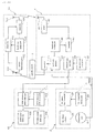
- Fig. 1 is a system constitutional view of the theft prevention device.
- an electronic key 15 includes a receiver 152 which is connected to a receiver antenna 151, a transmitter 154 which has a transmitter antenna 153, a first ID code memory part 155 which prestores a first ID code, and a comparator 156 which compares a code received by the receiver 152 and the first ID code which is stored in the first ID code memory part 155.
- the electronic key 15 includes a battery not show in the drawing which functions as an operation power source and starts operation thereof upon manipulation of a start switch not shown in the drawing.
- the receiver unit 4 includes a receiver 42 which has a receiver antenna 41, a transmitter 43 which is connected to the transmitter antenna 3, a first ID code memory part 44, a first ID code generator 45, and a comparator 46 which compares a code received by the receiver 42 and a first ID code which is stored in the first ID code memory part 44. Further, the receiver unit 4 includes a second ID code memory part 47 and a second ID code generator 48.
- the handle lock module 2 includes a lock release determination part 21 which decides whether the rotation of the manipulation knob 6 is allowed, a lock release code memory part 22 which prestores a lock release code, and a lock release solenoid 23.
- the manipulation knob 6 is always capable of performing a push manipulation.
- the ECU 10 includes a control allowance determination part 101 which determines whether the start of the control is allowed or not, a control allowance code memory part 102 which stores a control allowance code, an ignition system control part 103, and a fuel supply system control part 104.
- a request signal REQ is inputted into the first ID code generator 45 of the receiver unit 4.
- the first ID code generator 45 reads the first ID code from the first ID code memory part 44 in response to the request signal REQ and supplies the first ID code to the transmitter 43.
- the transmitter 43 transmits the first ID code through the transmitter antenna 3.
- the receiver 152 of the electronic key 15 inputs a reception signal to the comparator 156.
- the comparator 156 compares the inputted reception signal with the first ID code stored in the first ID code memory part 155.
- the inputted reception signal is the first ID code transmitted from the receiver unit 4
- both signals agree with each other.
- the transmitter 154 transmits the first ID code stored in the first ID code memory part 155 from the transmitter 154 using the transmitter antenna 153.
- the receiver 42 inputs the reception signal to the comparator 46.
- the comparator 46 compares the inputted reception signal with the second ID code stored in the second ID code memory part 44.
- the second ID code generator 48 reads the second ID code stored in the second ID code memory part 47 and outputs the second ID code to the control allowance determination part 101 of the ECU 10 and the lock release determination part 21 of the handle lock module 2 respectively.
- control allowance determination part 101 of the ECU 10 when the second ID code is inputted to control allowance determination part 101, compares the second ID code with the control allowance code stored in the control allowance code memory part 102. When both codes agree with each other, the control start allowance is given to the ignition system control part 103 and the fuel supply system control part 104. Due to such an operation, the engine control of the motorcycle 1 can be started.
- the second ID code is compared with the lock release code stored in the lock release code memory part 22.
- the lock release solenoid 23 is driven thus releasing the handle lock and, at the same time, enabling the rotary manipulation of the manipulation knob 6. Due to such a constitution, the handle manipulation is allowed. Further, in addition to the push manipulation, locking of the rotary manipulation of the manipulation knob 6 is released and hence, the manipulation knob 6 becomes rotatable.
- the receiver unit 4 is not compatible with the handle lock module 2 and the ECU 10, the lock release determination part 21 and the control allowance determination part 101 do not bring about a collation result "agree" and hence, the engine control cannot be started and, at the same time, the handle locking and the locking of the manipulation knob 6 are also not released.
- the second ID code is set to prevent the occurrence of a case that a third party obtains an electronic key and a receiver unit additionally, exchanges the receiver unit 4 with the existing receiver unit 4 of the motorcycle 1 so as to release the handle lock of the motorcycle 1 or to start the engine control by the ECU 10. That is, even when the electronic key 15 and the receiver unit 4 are aligned with each other by exchanging the receiver unit 4, unless the handle lock module 2 and the ECU 10 are not exchanged, the second ID code outputted from the second ID code generator 46 does not agree with the lock release code and the control allowance code with each other and hence, the engine cannot be started and the handle lock cannot be released.
- Fig. 3 is a block diagram showing a second ID code registration function, and more particularly is a view showing a function necessary for registration processing at the time of assembling a finished vehicle in a factory.
- the second ID code is preliminarily written in the ID writing device 16.
- the ID writing device 16 is a dedicated device for allowing the writing of data into the second ID code memory part 47 which constitutes a RAM.
- a reading/writing part 100 is provided.
- the second ID code is read from the second ID code memory part 47 and the second ID code is written in the control allowance code memory part 102 of the ECU 10 and the lock release code memory part 22 of the handle lock module 2.
- the ID code may be individually written in the second ID code memory part 47, the control allowance code memory part 105 and the lock release code memory part 22 using the ID writing device 16.
- Fig. 4 is a block diagram showing the second ID code registration function when the receiver unit 4 is exchanged.
- the ECU 10 includes a throttle counter 105, an ID buffer 106 and a collation part 107.
- the ID buffer 106 can store six counter values corresponding to six-digit second ID code, for example.
- An indicator 14A is mounted on the instrument panel 14, for example.
- the counter values of the throttle counter 105 are incremented when the opening/closing of the throttle (a series of operations in which the throttle is opened to a preset opening angle and is succeedingly fully closed) is detected by the throttle sensor 11A until a preset time (for example, 5 seconds) elapses from a point of time that the standing/storing of the side stand 12 is detected based on an output of the side stand switch 13.
- a preset time for example, 5 seconds
- the counter values of the throttle counter 105 at this point of time are written in the ID buffer 106.
- the detection of the opening/closing of the throttle and the counting by the throttle counter 105 are performed again for inputting the next digit number to the ID buffer 106.
- the standing/storing of the side stand 12, the opening/closing of the throttle, the increment of the counter values and the writing of the counter values to the ID buffer 106 are repeated until the predetermined number (6 in this case) of counter values is stored in the ID buffer 106. Then, when predetermined number of counter values is stored in the ID buffer 106 and the side stand 12 is stood or stored in response to a sign by turning on the indicator 14A, the registration is allowed.
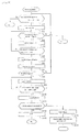
- Fig. 5 is a flow chart showing registration processing of the second ID code when the receiver unit is exchanged.
- a power source is connected to the ECU 10.
- the power source is a battery for registering the second ID code and is connected to the ECU 10 using an inspection tool (a dedicated harness). For example, a coupler which connects a crank pulser and the ECU 10 is removed and the power source is connected to the ECU 10 through the coupler.
- an inspection tool a dedicated harness
- a coupler which connects a crank pulser and the ECU 10 is removed and the power source is connected to the ECU 10 through the coupler.
- the battery is connected to the ECU 10 temporarily, is separated from the ECU 10 once thereafter, and is connected to the ECU 10 again.
- step S1 it is monitored whether the side stand switch 13 is changed over from an ON state to an OFF state and is again changed over from the OFF state to the ON state or not. If this determination is affirmative, the processing advances to step S2 in which the indicator 14A is flickered. Due to this flickering of the indicator 14A, a user can recognize that the registration mode is in progress.
- step S3 it is determined whether the throttle 11 is operated such that the throttle 11 is once opened and is again closed or not in response to an output of the throttle sensor 11A. If this operation is detected, the value of the throttle counter 105 is incremented in step S 4.
- step S5 it is monitored whether the side stand switch 13 is changed over from the ON state to the OFF state and is again changed over from the OFF state to the ON state. Steps S3 to S5 are repeated until this determination becomes affirmative, and when the determination in step S5 becomes affirmative, the processing advances to step S6 and the counter values at this point of time are transferred to the ID buffer 106.
- the ID buffer 106 includes a region for the number of digits of the second ID code, wherein the inputted counter values are sequentially stored from the lower digit. When the counter values are transferred to the ID buffer 106, the counter values of the throttle counter 105 are cleared in step S7.
- step S8 it is determined whether the ID buffer 106 stores the counter values of the full digit number, that is, the predetermined digit number such as six digits or not. If this determination is affirmative, the processing advances to step S9 and the indicator 14A is turned on to inform a user that the predetermined digit number is inputted.
- step S10 the presence or non-presence of a sign which allows a sign of the allowance of the registration from a user is determined by monitoring whether the side stand switch 13 is changed over from an ON state to an OFF state and is changed over from the OFF state to the ON state or not.
- step S10 When it is determined that the registration allowance sign from the user is inputted in step S10, the processing advances to step S11 and the indicator 14A is extinguished. Then, the processing advances to step S12 in which it is determined whether the counter values which are stored in the ID buffer 106 agree with the registered ID, that is, the control allowance code or not by the collation part 107.
- step S12 When the control allowance code and the counter values of the ID buffer 106 agree with each other in step S12, the processing advances to step S13 and a display indicative of the completion of registration is performed by flickering of the indicator 14A.
- step S14 the control allowance code is transferred to the receiver unit 4 from the ECU 10. In the receiver unit 4, the transferred control allowance code is registered to the second ID code memory part 47 as the second ID code.
- step S12 When the determination in step S12 is negative, the processing advances to step S15 and an error display is performed.
- the error display is, for example, performed by flickering of the indicator 14A.
- the flickering of the indicator 14A here differs, for displaying an error, from flickering at other timings in terms of ON/OFF cycles.
- the error display for example, the indicator 14A is extinguished by finishing the open/close operation of the throttle.
- the error is not confirmed based on one determination but the determination is performed the predetermined times, for example, five re-entries, and when the values of the throttle counter do not collate with the second ID code even in such a case, the error may be confirmed. Accordingly, when the determination in step S9 is negative, when the number of determination is up to five times, the processing returns to step S1, and when the collation is not successful even with five determinations, the registration processing is not accepted.
- step S1 and step S3 when the change of the ON/OFF state of the side stand switch 13 or the throttle open/close operation is not performed until the preset determination time elapses, the processing of the flow chart is finished.
- Fig. 6 symbols equal to the symbols shown in Fig. 4 indicate identical or similar parts.
- the values of the throttle counter are stored by the standing/storing of the side stand and the manipulation of the throttle.
- the values of the throttle counter corresponding to the predetermined number that is, the predetermined digit number are stored in the ID buffer 106
- the second ID code of the predetermined digit number is written and registered in the control allowance code memory part 102 from the ID buffer 106.
- the registration technique of the second ID code has been explained in conjunction with the example in which the prestored first ID code is transmitted from the receiver unit 4 in response to the push manipulation of the manipulation knob 6.
- the present invention can be modified as follows. That is, the receiver unit 4 may not transmit the fixed first ID code in response to the request signal REQ but may transmit different numerical values, that is, a cipher each time in response to the request signal REQ.
- a means which deciphers this cipher may be a calculation formula which outputs the first ID code in response to this cipher as an input, for example.
- a calculation formula equal to the calculation formula in the electronic key 15 is provided to the receiver unit 4, and the first reference code based on the output cipher is preliminarily calculated. Then, the first reference code and the first ID code received from the electronic key 15 are collated with each other and the second ID code is outputted only when the authorized first ID code is received.
- Fig. 7 is a constitutional view of an immobilizer system.
- a memory 26 in which a first ID code is prestored and a transmitter 27 for transmitting the first ID code are incorporated.
- the transmitter 27 of the key 25 and the key cylinder 28 are joined by an induction coil 29, for example.
- electricity is supplied to the transmitter 27 via the induction coil 29.
- the transmitter 27 responds to the supply of the electricity, reads the authentication code from the memory 26, and transmits the authentication code to the key cylinder 28 side. This authentication code is received by a receiver 30 and the reception is notified to an immobilizer CPU 32.
- the immobilizer CPU 32 includes, as functions thereof, a memory part 33 which stores a reference ID code, and a collation part 34 which compares the notified first ID code and the reference ID code. When it is determined that the first ID code and the reference ID code agree with each other, the collation part 34 transmits a second ID code stored in a second ID code memory part 35 to the ECU 10.
- the ECU 10 in the same manner as the operation of the smart key system, collates the second ID code inputted from the immobilizer CPU 32 with a control allowance code. When both ID codes agree with each other as a result of collation, the ECU 10 inputs signals which allow the ignition system control part 103 and the fuel supply system control part 104 to perform operations thereof.
- steps for registering the second ID code when a finished vehicle is assembled, when the key 25 and the key cylinder 28 are exchanged with brand new key and key cylinder, and when the ECU 10 is exchanged with a brand new ECU are substantially equal to the steps adopted in the above-mentioned smart key system.
- the second ID code is notified to a user as an authentication code at the time of selling the vehicle, and when the exchange of the key system or the exchange of the ECU is performed, the second ID code which only the user is authorized to know is re-registered using the above-mentioned registration method.
- a third party who is not notified the authentication code cannot succeed in the collation using the second ID code even when the third party exchanges the receiver unit 4 and the ECU 10. Accordingly, it is possible to surely prevent the motorcycle 1 from being moved by exchanging with brand new receiver unit 4 or ECU 10 without using the authorized key.
- the second ID code may be described in a card and the card may be handed over or may be mailed. However, the second ID code may be notified to the user using an electronic mail.
- the present invention has been explained heretofore in accordance with the best mode for carrying out the invention, the present invention is not limited to such a best mode and various modifications are conceivable.
- the output signals of respective sensors for detecting standing/storing of the side stand and the opening/closing of the throttle are used as means for registering the second ID code.
- the manipulation or the number of manipulations of other switch mounted on the vehicle for example, a blinker switch or a brake switch may be detected and a detection result may be used as an instruction for registering the second ID code.
- agreement of the collation of the ID codes includes a case in which a preset relationship is established between both codes which agree with each other or are collated with each other.
Landscapes
- Engineering & Computer Science (AREA)
- Mechanical Engineering (AREA)
- Lock And Its Accessories (AREA)
- Combined Controls Of Internal Combustion Engines (AREA)
- Burglar Alarm Systems (AREA)
Abstract
Description
- The present invention relates to a vehicle theft prevention device, and more particularly to a vehicle theft prevention device which is suitable for preventing other person from taking an action to move a vehicle using an ID code outputting device.
- As a vehicle theft prevention device, there has been known a vehicle theft prevention device which allows starting of an engine only when cipher numbers agree with each other. For example, a vehicle theft prevention device described in
Japanese Patent 325224
[Patent document 1]Japanese Patent 325224 - According to the theft prevention device described in the
patent document 1, since the ID code is written when the use of the theft prevention device is started firstly and hence, even when one attempts to move the vehicle by exchanging only the theft prevention unit while using the control unit as it is, the exchanged theft prevention unit cannot generate the same ID code equal to the memory code which is firstly written in the control unit and hence, one cannot operate the control unit whereby it is possible to obtain a theft prevention effect. - However, by obtaining and using a brand new theft prevention unit, it is possible to rewrite the memory code stored in the existing control unit thus making the ID code and the memory code agree with each other and hence, even a third party can move the vehicle.
- Accordingly, it is an object of the present invention to provide, in a system which is constituted of a theft prevention ID code generation device and a control unit, a vehicle theft prevention device which can effectively prevent one from moving a vehicle using an exchanged theft prevention ID code generation device.
- The present invention for achieving the above-mentioned object is, in a vehicle theft prevention device which includes a portable transmitter which is arranged outside a vehicle for transmitting a first ID code, a receiver unit which receives the first ID code transmitted from the portable transmitter and outputs a second ID code when the first ID code agrees with a preset first reference code, and an engine control unit which starts an engine control when the second ID code is inputted to the engine control unit and the second ID code agrees with a preset second reference code, firstly characterized in that the vehicle theft prevention device includes a code inputting means for registering the second reference code to the engine control unit, and a means which writes the registered second reference code into the receiver unit as the second ID code.
- Further, the present invention is secondly characterized in that the portable transmitter includes a deciphering means which decides the first ID code based on a cipher inputted from the receiver unit, and the receiver unit includes a reference code decision means which decides the first reference code based on the outputted cipher.
- Further, the present invention is thirdly characterized in that a code which is inputted for registering the second reference code to the engine control unit is inputted in response to an open/close manipulation of a throttle provided to the vehicle and a standing/storing manipulation of a side stand provided to the vehicle.
- Further, the present invention is fourthly characterized in that the second reference code is a value intrinsic to each vehicle.
- According to the present invention having the first feature and the second feature, in the device which allows an operation of the engine control device by collating the second ID code inputted from the receiver unit with the second reference code in the engine control device, when the engine control device is exchanged with a brand new engine control device, an inputted code can be registered as the second reference code. Even when a third party inputs the erroneous code and the code is registered, the registered code does not agree with the second ID code inputted from the receiver unit and hence, the third party cannot make the engine control unit operable. Accordingly, only a user who is authorized to know the second reference code, that is, the second ID code can authentically register the second reference code thus eventually preventing the third party from moving the vehicle by exchanging the engine control unit.
- Further, in exchanging the receive unit with a brand new receiver unit, when the inputted code is the authorized second reference code, the second reference code can be registered in the receiver unit as the second ID code. Accordingly, when the inputted code differs from the authorized second reference code, the second ID code is not registered in the receiver unit and hence, even when the transmitter which transmits the first ID code and the receiver unit are exchanged as a set, the second ID code is not outputted thus eventually preventing a person other than the user which is authorized to know the second reference ID code from moving the vehicle.
- According to the present invention having the third feature, the throttle manipulation means or the side stand manipulation which is generally provided to the vehicle is used as an inputting means of an instruction or numerical values for generating the code and the code can be registered and hence, it is unnecessary to provide a dedicated ten key or a dedicated manipulation switch. Accordingly, it is possible to achieve the theft prevention effect without adding parts by newly forming a space for inputting the second reference code.
- According to the fourth feature, the second reference code is the value intrinsic to each vehicle and hence, only the user of the vehicle is authorized to know the second reference code. Accordingly, even when the engine control unit and the receiver unit are newly mounted, a third party cannot start the engine unless the third party accurately input the second reference code and hence, it is possible to achieve a remarkable theft prevention effect.
- [Fig. 1]
A system constitutional view of a theft prevention device according to one embodiment of the present invention. - [Fig. 2]
A rear perspective view of a scooter-type motorcycle which mounts the theft prevention device of one embodiment of the present invention thereon. - [Fig. 3]
A block diagram showing a second ID code registration function, and more particularly, a view showing a function necessary for registration processing at the time of assembling a finished vehicle in a factory. - [Fig. 4]
A block diagram showing the second ID code registration function when the receiver unit is exchanged. - [Fig. 5]
A flow chart showing registration processing of the second ID code when the receiver unit is exchanged. - [Fig. 6]
A functional block diagram showing the registration function of the second ID code when only an ECU is exchanged with a brand new ECU. - [Fig. 7]
A constitutional view of an immobilizer system. - Hereinafter, one embodiment of the present invention is explained in conjunction with drawings. Fig. 2 is a rear perspective view of a scooter-type motorcycle which mounts a theft prevention device of one embodiment of the present invention thereon. In the drawing, the theft prevention device which is mounted on the
motorcycle 1 includes ahandle lock module 2, atransmitter antenna 3 and areceiver unit 4. Thehandle lock module 2 is mounted on a main frame not shown in the drawing such that amanipulation knob 6 is exposed to the outside from aninner cover 5. By extending or retracting a lock pin with the rotatable manipulation of themanipulation knob 6, it is possible to fix a head pipe and a stem shaft which supports ahandle 7 or to release fixing of the head pipe and the stem shaft. Themanipulation knob 6 also functions as a main switch of themotorcycle 1 and a manipulation portion for starting an engine. - The
transmitter antenna 3 is housed in a back side of theinner cover 5, while thereceiver unit 4 is mounted on a seat rail portion not shown in the drawing which is arranged below aseat 8. Abattery 9 which constitutes a power source of themotorcycle 1 is mounted on an approximately center portion of a vehicle body, and an engine control unit (ECU) 10 which receives the supply of electricity from thebattery 9 and controls an ignition system and a fuel supply system of themotorcycle 1 is mounted on the approximately center portion of a vehicle body. In this embodiment, theECU 10 and athrottle body 11 are integrally formed. - The
manipulation knob 6 is configured such that the rotational manipulation thereof is usually prohibited and the prohibition is released when determination processing of a theft prevention ID code is performed and, thereafter, the ID code agrees with a preset memory code. In the same manner, also with respect to theECU 10, the start of an engine control is allowed when the ID code and the memory code agree with each other. - A
side stand 12 is mounted on a left side of a vehicle body of themotorcycle 1. Theside stand 12 is pivotally supported on a side frame (not shown in the drawing) on the left side of the vehicle body, wherein theside stand 12 is used in a downwardly rotated manner in standing themotorcycle 1 in a leftwardly inclined posture in a non-traveling state and, as described later, theside stand 12 is used as an input means of the theft prevention ID code. Aside stand switch 13 is mounted on a pivotal support portion of theside stand 12 for detecting whether theside stand 12 is stored on the vehicle body side or is downwardly rotated to assume a use state. Theside stand switch 13 outputs an "OFF" signal when theside stand 12 is pulled out to assume the use state and outputs an "ON" signal when theside stand 12 is stored on the vehicle body side. - An
instrument panel 14 is provided in front of thehandle 7. Theinstrument panel 14 includes a theft prevention device indicator besides a speedo meter, rotational speedo meter, residual fuel meter and an engine water temperature meter. - Fig. 1 is a system constitutional view of the theft prevention device. In Fig. 1, an
electronic key 15 includes areceiver 152 which is connected to areceiver antenna 151, atransmitter 154 which has atransmitter antenna 153, a first IDcode memory part 155 which prestores a first ID code, and acomparator 156 which compares a code received by thereceiver 152 and the first ID code which is stored in the first IDcode memory part 155. Theelectronic key 15 includes a battery not show in the drawing which functions as an operation power source and starts operation thereof upon manipulation of a start switch not shown in the drawing. - The
receiver unit 4 includes areceiver 42 which has areceiver antenna 41, a transmitter 43 which is connected to thetransmitter antenna 3, a first IDcode memory part 44, a firstID code generator 45, and acomparator 46 which compares a code received by thereceiver 42 and a first ID code which is stored in the first IDcode memory part 44. Further, thereceiver unit 4 includes a second IDcode memory part 47 and a secondID code generator 48. - The
handle lock module 2 includes a lockrelease determination part 21 which decides whether the rotation of themanipulation knob 6 is allowed, a lock releasecode memory part 22 which prestores a lock release code, and alock release solenoid 23. Here, themanipulation knob 6 is always capable of performing a push manipulation. - The ECU 10 includes a control
allowance determination part 101 which determines whether the start of the control is allowed or not, a control allowancecode memory part 102 which stores a control allowance code, an ignitionsystem control part 103, and a fuel supplysystem control part 104. - In the above-mentioned constitution, when the
manipulation knob 6 which is mounted on thehandle lock module 2 is manipulated by pushing, a request signal REQ is inputted into the firstID code generator 45 of thereceiver unit 4. The firstID code generator 45 reads the first ID code from the first IDcode memory part 44 in response to the request signal REQ and supplies the first ID code to the transmitter 43. The transmitter 43 transmits the first ID code through thetransmitter antenna 3. - The
receiver 152 of theelectronic key 15 inputs a reception signal to thecomparator 156. Thecomparator 156 compares the inputted reception signal with the first ID code stored in the first IDcode memory part 155. When the inputted reception signal is the first ID code transmitted from thereceiver unit 4, both signals agree with each other. In response to the result of agreement, thetransmitter 154 transmits the first ID code stored in the first IDcode memory part 155 from thetransmitter 154 using thetransmitter antenna 153. - In the
receiver 42 of thereceiver unit 4, in the same manner as theelectronic key 15, thereceiver 42 inputs the reception signal to thecomparator 46. Thecomparator 46 compares the inputted reception signal with the second ID code stored in the second IDcode memory part 44. When the inputted reception signal is the first ID code transmitted from theelectronic key 15, both signals agree with each other. In response to the result of agreement, the secondID code generator 48 reads the second ID code stored in the second IDcode memory part 47 and outputs the second ID code to the controlallowance determination part 101 of theECU 10 and the lockrelease determination part 21 of thehandle lock module 2 respectively. - The control
allowance determination part 101 of theECU 10, when the second ID code is inputted to controlallowance determination part 101, compares the second ID code with the control allowance code stored in the control allowancecode memory part 102. When both codes agree with each other, the control start allowance is given to the ignitionsystem control part 103 and the fuel supplysystem control part 104. Due to such an operation, the engine control of themotorcycle 1 can be started. - When the second code is inputted to the lock
release determination part 21 of thehandle lock module 2, the second ID code is compared with the lock release code stored in the lock releasecode memory part 22. When both codes agree with each other, thelock release solenoid 23 is driven thus releasing the handle lock and, at the same time, enabling the rotary manipulation of themanipulation knob 6. Due to such a constitution, the handle manipulation is allowed. Further, in addition to the push manipulation, locking of the rotary manipulation of themanipulation knob 6 is released and hence, themanipulation knob 6 becomes rotatable. - However, the
receiver unit 4 is not compatible with thehandle lock module 2 and theECU 10, the lockrelease determination part 21 and the controlallowance determination part 101 do not bring about a collation result "agree" and hence, the engine control cannot be started and, at the same time, the handle locking and the locking of themanipulation knob 6 are also not released. - In this embodiment, the second ID code is set to prevent the occurrence of a case that a third party obtains an electronic key and a receiver unit additionally, exchanges the
receiver unit 4 with the existingreceiver unit 4 of themotorcycle 1 so as to release the handle lock of themotorcycle 1 or to start the engine control by theECU 10. That is, even when theelectronic key 15 and thereceiver unit 4 are aligned with each other by exchanging thereceiver unit 4, unless thehandle lock module 2 and theECU 10 are not exchanged, the second ID code outputted from the secondID code generator 46 does not agree with the lock release code and the control allowance code with each other and hence, the engine cannot be started and the handle lock cannot be released. - Subsequently, the manner of registering the second ID code (also applicable to the lock release code and the control allowance code in the same manner) in the
motorcycle 1 is explained. Fig. 3 is a block diagram showing a second ID code registration function, and more particularly is a view showing a function necessary for registration processing at the time of assembling a finished vehicle in a factory. In Fig. 3, in the second IDcode memory part 47 of thereceiver unit 4, the second ID code is preliminarily written in theID writing device 16. TheID writing device 16 is a dedicated device for allowing the writing of data into the second IDcode memory part 47 which constitutes a RAM. - As a part which performs a function of a microcomputer in the
ECU 10, a reading/writingpart 100 is provided. When thereceiver unit 4 and theECU 10 are connected with each other due to this function, the second ID code is read from the second IDcode memory part 47 and the second ID code is written in the control allowancecode memory part 102 of theECU 10 and the lock releasecode memory part 22 of thehandle lock module 2. - Here, besides such a constitution, at the time of assembling a finished vehicle in a factory, the ID code may be individually written in the second ID
code memory part 47, the control allowancecode memory part 105 and the lock releasecode memory part 22 using theID writing device 16. - Fig. 4 is a block diagram showing the second ID code registration function when the
receiver unit 4 is exchanged. In Fig. 4, theECU 10 includes athrottle counter 105, anID buffer 106 and acollation part 107. TheID buffer 106 can store six counter values corresponding to six-digit second ID code, for example. Anindicator 14A is mounted on theinstrument panel 14, for example. - The counter values of the
throttle counter 105 are incremented when the opening/closing of the throttle (a series of operations in which the throttle is opened to a preset opening angle and is succeedingly fully closed) is detected by thethrottle sensor 11A until a preset time (for example, 5 seconds) elapses from a point of time that the standing/storing of the side stand 12 is detected based on an output of the side standswitch 13. When the opening/closing of the throttle is not detected until the preset time elapses, the counter values of thethrottle counter 105 are reset. - Then, upon detection of the standing/storing of the side stand 12 after opening/closing of the throttle, the counter values of the
throttle counter 105 at this point of time are written in theID buffer 106. When the side stand 12 is stood or stored after writing the counter values to theID buffer 106, the detection of the opening/closing of the throttle and the counting by thethrottle counter 105 are performed again for inputting the next digit number to theID buffer 106. - The standing/storing of the
side stand 12, the opening/closing of the throttle, the increment of the counter values and the writing of the counter values to theID buffer 106 are repeated until the predetermined number (6 in this case) of counter values is stored in theID buffer 106. Then, when predetermined number of counter values is stored in theID buffer 106 and the side stand 12 is stood or stored in response to a sign by turning on theindicator 14A, the registration is allowed. - When the registration is allowed, a row of counter values stored in the
ID buffer 106, that is, the six-digit number is written in thecollation part 107 and is collated with the control allowance code which is registered in the control allowancecode memory part 102 of theECU 10. When the collation result shows that the six-digit number agrees with the control allowance code, theindicator 14A is flickered and, at the same time, the control allowance code is read by accessing to the control allowancecode memory part 102 and is written in the second IDcode memory part 47 of thereceiver unit 4. - Fig. 5 is a flow chart showing registration processing of the second ID code when the receiver unit is exchanged. In a pre-stage of the flow chart, a power source is connected to the
ECU 10. The power source is a battery for registering the second ID code and is connected to theECU 10 using an inspection tool (a dedicated harness). For example, a coupler which connects a crank pulser and theECU 10 is removed and the power source is connected to theECU 10 through the coupler. Here, for removing noises, it may be preferable that the battery is connected to theECU 10 temporarily, is separated from theECU 10 once thereafter, and is connected to theECU 10 again. - In step S1, it is monitored whether the side stand
switch 13 is changed over from an ON state to an OFF state and is again changed over from the OFF state to the ON state or not. If this determination is affirmative, the processing advances to step S2 in which theindicator 14A is flickered. Due to this flickering of theindicator 14A, a user can recognize that the registration mode is in progress. - In step S3 , it is determined whether the
throttle 11 is operated such that thethrottle 11 is once opened and is again closed or not in response to an output of thethrottle sensor 11A. If this operation is detected, the value of thethrottle counter 105 is incremented instep S 4. - In step S5, it is monitored whether the side stand
switch 13 is changed over from the ON state to the OFF state and is again changed over from the OFF state to the ON state. Steps S3 to S5 are repeated until this determination becomes affirmative, and when the determination in step S5 becomes affirmative, the processing advances to step S6 and the counter values at this point of time are transferred to theID buffer 106. TheID buffer 106 includes a region for the number of digits of the second ID code, wherein the inputted counter values are sequentially stored from the lower digit. When the counter values are transferred to theID buffer 106, the counter values of thethrottle counter 105 are cleared in step S7. - In step S8, it is determined whether the
ID buffer 106 stores the counter values of the full digit number, that is, the predetermined digit number such as six digits or not. If this determination is affirmative, the processing advances to step S9 and theindicator 14A is turned on to inform a user that the predetermined digit number is inputted. In step S10, the presence or non-presence of a sign which allows a sign of the allowance of the registration from a user is determined by monitoring whether the side standswitch 13 is changed over from an ON state to an OFF state and is changed over from the OFF state to the ON state or not. - When it is determined that the registration allowance sign from the user is inputted in step S10, the processing advances to step S11 and the
indicator 14A is extinguished. Then, the processing advances to step S12 in which it is determined whether the counter values which are stored in theID buffer 106 agree with the registered ID, that is, the control allowance code or not by thecollation part 107. - When the control allowance code and the counter values of the
ID buffer 106 agree with each other in step S12, the processing advances to step S13 and a display indicative of the completion of registration is performed by flickering of theindicator 14A. In step S14, the control allowance code is transferred to thereceiver unit 4 from theECU 10. In thereceiver unit 4, the transferred control allowance code is registered to the second IDcode memory part 47 as the second ID code. - When the determination in step S12 is negative, the processing advances to step S15 and an error display is performed. The error display is, for example, performed by flickering of the
indicator 14A. The flickering of theindicator 14A here differs, for displaying an error, from flickering at other timings in terms of ON/OFF cycles. In the error display, for example, theindicator 14A is extinguished by finishing the open/close operation of the throttle. Here, the error is not confirmed based on one determination but the determination is performed the predetermined times, for example, five re-entries, and when the values of the throttle counter do not collate with the second ID code even in such a case, the error may be confirmed. Accordingly, when the determination in step S9 is negative, when the number of determination is up to five times, the processing returns to step S1, and when the collation is not successful even with five determinations, the registration processing is not accepted. - Here, in step S1 and step S3, when the change of the ON/OFF state of the side stand
switch 13 or the throttle open/close operation is not performed until the preset determination time elapses, the processing of the flow chart is finished. - Next, the registration function of the second ID code when only the
ECU 10 is exchanged with a brand new ECU is explained in conj unction with a functional block diagram shown in Fig. 6. In Fig. 6, symbols equal to the symbols shown in Fig. 4 indicate identical or similar parts. In theID buffer 106, the values of the throttle counter are stored by the standing/storing of the side stand and the manipulation of the throttle. When the values of the throttle counter corresponding to the predetermined number, that is, the predetermined digit number are stored in theID buffer 106, the second ID code of the predetermined digit number is written and registered in the control allowancecode memory part 102 from theID buffer 106. - The processing when only the
ECU 10 is exchanged with a brand new ECU is similar to the processing described in the flow chart shown in Fig. 5. However, when theECU 10 is exchanged with a brand new ECU, the function of thecollation part 107 is unnecessary and hence, in the flow chart shown in Fig. 5, the processing is modified such that step S12 is skipped and the processing advances to step S13 from step S11. - In the above-mentioned embodiment, the registration technique of the second ID code has been explained in conjunction with the example in which the prestored first ID code is transmitted from the
receiver unit 4 in response to the push manipulation of themanipulation knob 6. However, the present invention can be modified as follows. That is, thereceiver unit 4 may not transmit the fixed first ID code in response to the request signal REQ but may transmit different numerical values, that is, a cipher each time in response to the request signal REQ. A means which deciphers this cipher may be a calculation formula which outputs the first ID code in response to this cipher as an input, for example. A calculation formula equal to the calculation formula in theelectronic key 15 is provided to thereceiver unit 4, and the first reference code based on the output cipher is preliminarily calculated. Then, the first reference code and the first ID code received from the electronic key 15 are collated with each other and the second ID code is outputted only when the authorized first ID code is received. - The above-mentioned embodiment is directed to the so-called smart key system which enables the control by the
ECU 10 and releases the handle lock in a state that a rider carries theelectronic key 15 and pushes themanipulation knob 6 when the rider approaches the vehicle. The present invention is also applicable to an immobilizer. Fig. 7 is a constitutional view of an immobilizer system. In Fig. 7, in anignition key 25, amemory 26 in which a first ID code is prestored and atransmitter 27 for transmitting the first ID code are incorporated. Thetransmitter 27 of the key 25 and thekey cylinder 28 are joined by aninduction coil 29, for example. When the rider inserts the key 25 into thekey cylinder 28 and turns the key 25, electricity is supplied to thetransmitter 27 via theinduction coil 29. Thetransmitter 27 responds to the supply of the electricity, reads the authentication code from thememory 26, and transmits the authentication code to thekey cylinder 28 side. This authentication code is received by a receiver 30 and the reception is notified to animmobilizer CPU 32. - The
immobilizer CPU 32 includes, as functions thereof, a memory part 33 which stores a reference ID code, and acollation part 34 which compares the notified first ID code and the reference ID code. When it is determined that the first ID code and the reference ID code agree with each other, thecollation part 34 transmits a second ID code stored in a second IDcode memory part 35 to theECU 10. - The
ECU 10, in the same manner as the operation of the smart key system, collates the second ID code inputted from theimmobilizer CPU 32 with a control allowance code. When both ID codes agree with each other as a result of collation, theECU 10 inputs signals which allow the ignitionsystem control part 103 and the fuel supplysystem control part 104 to perform operations thereof. - In the immobilizer system having such a constitution, steps for registering the second ID code when a finished vehicle is assembled, when the key 25 and the
key cylinder 28 are exchanged with brand new key and key cylinder, and when theECU 10 is exchanged with a brand new ECU are substantially equal to the steps adopted in the above-mentioned smart key system. - In the above-mentioned embodiment, the second ID code is notified to a user as an authentication code at the time of selling the vehicle, and when the exchange of the key system or the exchange of the ECU is performed, the second ID code which only the user is authorized to know is re-registered using the above-mentioned registration method. A third party who is not notified the authentication code cannot succeed in the collation using the second ID code even when the third party exchanges the
receiver unit 4 and theECU 10. Accordingly, it is possible to surely prevent themotorcycle 1 from being moved by exchanging with brandnew receiver unit 4 orECU 10 without using the authorized key. - Here, as means which notifies the user of the second ID code, the second ID code may be described in a card and the card may be handed over or may be mailed. However, the second ID code may be notified to the user using an electronic mail.
- Although the present invention has been explained heretofore in accordance with the best mode for carrying out the invention, the present invention is not limited to such a best mode and various modifications are conceivable. For example, as means for registering the second ID code, the output signals of respective sensors for detecting standing/storing of the side stand and the opening/closing of the throttle are used. However, in place of input signals obtained by detecting the standing/storing of the side stand and the opening/closing of the throttle, the manipulation or the number of manipulations of other switch mounted on the vehicle, for example, a blinker switch or a brake switch may be detected and a detection result may be used as an instruction for registering the second ID code.
- Further, the agreement of the collation of the ID codes includes a case in which a preset relationship is established between both codes which agree with each other or are collated with each other.
- 1: motorcycle, 2: handle lock module, 3: transmitter, 4: receiver unit, 6: manipulation knob, 10: ECU, 11: throttle body, 11A: throttle sensor, 12: side stand, 13: side stand switch, 14A: indicator, 15: electronic key, 16: ID writing device, 22: lock release code memory part, 47: second ID code memory part, 102: control allowance code memory part
Claims (4)
- A vehicle theft prevention device comprising:a portable transmitter (3) which is arranged outside a vehicle for transmitting a first ID code;a receiver unit (4) which receives the first ID code transmitted from the portable transmitter (3) and outputs a second ID code when the first ID code agrees with a preset first reference code; andan engine control unit (10) which starts an engine control when the second ID code is inputted to the engine control unit (10) and the second ID code agrees with a preset second reference code, whereinthe vehicle theft prevention device includes a code inputting means for recording the second reference code to the engine control unit (10), and a means which writes the registered second reference code into the receiver unit as the second ID code.
- A vehicle theft prevention device according to claim 1, wherein the portable transmitter (3) includes a deciphering means which decides the first ID code based on a cipher inputted from the receiver unit (4), and
the receiver unit (4) includes a reference code decision means which decides the first reference code based on the outputted cipher. - A vehicle theft prevention device according to claim 1 or 2, wherein a code which is inputted for registering the second reference code to the engine control unit (10) is inputted in response to an open/close manipulation of a throttle provided to the vehicle and a standing/storing manipulation of a side stand provided to the vehicle.
- A vehicle theft prevention device according to any one of claims 1 to 3, wherein the second reference code is a value intrinsic to each vehicle.
Applications Claiming Priority (1)
| Application Number | Priority Date | Filing Date | Title |
|---|---|---|---|
| JP2006098995A JP4716428B2 (en) | 2006-03-31 | 2006-03-31 | Vehicle antitheft device |
Publications (2)
| Publication Number | Publication Date |
|---|---|
| EP1839957A1 true EP1839957A1 (en) | 2007-10-03 |
| EP1839957B1 EP1839957B1 (en) | 2008-09-24 |
Family
ID=38031472
Family Applications (1)
| Application Number | Title | Priority Date | Filing Date |
|---|---|---|---|
| EP20070101789 Ceased EP1839957B1 (en) | 2006-03-31 | 2007-02-06 | Vehicle theft prevention device |
Country Status (7)
| Country | Link |
|---|---|
| US (1) | US7667348B2 (en) |
| EP (1) | EP1839957B1 (en) |
| JP (1) | JP4716428B2 (en) |
| CN (1) | CN101046897B (en) |
| BR (1) | BRPI0702025B1 (en) |
| DE (1) | DE602007000137D1 (en) |
| TW (1) | TW200738499A (en) |
Cited By (2)
| Publication number | Priority date | Publication date | Assignee | Title |
|---|---|---|---|---|
| WO2016050876A1 (en) * | 2014-10-01 | 2016-04-07 | U-Shin France Sas | Anti-theft device for a motor vehicle having a safety device preventing switching off of the motor, and motor vehicle comprising such an anti-theft device |
| EP3354522A1 (en) * | 2017-01-25 | 2018-08-01 | TVS Motor Company Limited | Immobilizer for a two-wheeled vehicle |
Families Citing this family (25)
| Publication number | Priority date | Publication date | Assignee | Title |
|---|---|---|---|---|
| US9202328B2 (en) * | 2007-12-03 | 2015-12-01 | International Frontier Technology Laboratory, Inc. | Authentication verifying method, authentication verifying member and authentication verifying member producing method |
| JP2010017129A (en) * | 2008-07-10 | 2010-01-28 | Honda Motor Co Ltd | Antitheft device for equipment |
| DE102008035243B4 (en) * | 2008-07-29 | 2016-12-22 | Continental Automotive Gmbh | Switchgear for a vehicle with an electronic immobilizer and method for actuating an electronic immobilizer |
| JP5205217B2 (en) * | 2008-11-04 | 2013-06-05 | 本田技研工業株式会社 | Anti-theft device for motorcycles |
| KR101091573B1 (en) | 2009-09-10 | 2011-12-13 | 대림자동차공업주식회사 | Starting device and method of two-wheeled vehicle |
| JP5162566B2 (en) * | 2009-12-09 | 2013-03-13 | 本田技研工業株式会社 | Anti-theft device for outboard motor |
| US8725330B2 (en) | 2010-06-02 | 2014-05-13 | Bryan Marc Failing | Increasing vehicle security |
| JP5643171B2 (en) * | 2011-10-14 | 2014-12-17 | 株式会社東海理化電機製作所 | Electronic key |
| CN111216680B (en) * | 2011-11-08 | 2021-09-10 | 睿能创意公司 | Apparatus, method and article for vehicle safety |
| JP5596012B2 (en) * | 2011-12-28 | 2014-09-24 | 本田技研工業株式会社 | Motorcycle |
| CA2890734A1 (en) | 2012-11-12 | 2014-05-15 | Indian Motorcycle International, LLC | Two-wheeled vehicle |
| JP5487334B2 (en) * | 2013-01-21 | 2014-05-07 | 本田技研工業株式会社 | Anti-theft device for motorcycles |
| CN103935321B (en) * | 2013-01-21 | 2016-04-13 | 广东高标电子科技有限公司 | A kind of battery-driven car based on recognition code starts control method |
| JP5487335B2 (en) * | 2013-01-21 | 2014-05-07 | 本田技研工業株式会社 | Anti-theft device for motorcycles |
| CN103287389B (en) * | 2013-04-11 | 2016-03-16 | 力帆实业(集团)股份有限公司 | A kind of bidirectional transfer of information that utilizes realizes antitheft engine anti-theft method and system |
| DE202013006900U1 (en) | 2013-08-01 | 2014-11-03 | C. & E. Fein Gmbh | machine tool |
| NO2884309T3 (en) * | 2013-08-01 | 2018-09-08 | ||
| CN106256616B (en) * | 2015-06-19 | 2018-10-19 | 株式会社三国 | vehicle anti-theft device |
| JP6851044B2 (en) * | 2016-12-22 | 2021-03-31 | 朝日電装株式会社 | Engine starter |
| EP3339110B1 (en) * | 2016-12-22 | 2020-02-05 | Asahi Denso Co., Ltd. | Engine starting device |
| PH12019501866B1 (en) * | 2017-04-05 | 2023-08-04 | Gogoro Inc | Systems for operating a vehicle and associated methods |
| US11649001B2 (en) * | 2017-12-08 | 2023-05-16 | Patrick Zitt | Kickstand mounted alarm device |
| JP6723279B2 (en) * | 2018-03-20 | 2020-07-15 | 本田技研工業株式会社 | In-vehicle authentication device, method, and program |
| JP7191319B2 (en) * | 2018-12-05 | 2022-12-19 | 朝日電装株式会社 | wireless communication system |
| CN111434533B (en) * | 2019-01-15 | 2022-01-18 | 浙江吉利汽车研究院有限公司 | Vehicle key searching method and system |
Citations (3)
| Publication number | Priority date | Publication date | Assignee | Title |
|---|---|---|---|---|
| EP0630785A2 (en) * | 1993-06-23 | 1994-12-28 | Adam Opel Ag | Apparatus for controlling of a motor for vehicles |
| DE19606265A1 (en) * | 1996-02-21 | 1997-08-28 | Opel Adam Ag | Anti-theft device for motor vehicles and anti-theft method |
| EP1464545A2 (en) * | 2003-03-28 | 2004-10-06 | HONDA MOTOR CO., Ltd. | Engine control unit |
Family Cites Families (12)
| Publication number | Priority date | Publication date | Assignee | Title |
|---|---|---|---|---|
| JPS60248485A (en) * | 1984-05-21 | 1985-12-09 | 川崎重工業株式会社 | Side stand device for motorcycle |
| JP3252244B2 (en) | 1993-09-27 | 2002-02-04 | ヤマハ発動機株式会社 | Anti-theft device |
| JPH07156752A (en) * | 1993-12-07 | 1995-06-20 | Suzuki Motor Corp | Vehicle anti-theft device |
| DE69536106D1 (en) * | 1994-04-14 | 2010-10-28 | Fujitsu Ten Ltd | Anti-theft device for vehicles |
| JPH08216947A (en) * | 1995-02-15 | 1996-08-27 | Rhythm Watch Co Ltd | Bicycle theft preventing device |
| JP3493134B2 (en) * | 1998-05-14 | 2004-02-03 | 株式会社小松製作所 | Vehicle unlocking device |
| JP2000108848A (en) * | 1998-10-02 | 2000-04-18 | Toyota Motor Corp | Immobilizer device |
| TWI242511B (en) * | 2001-02-19 | 2005-11-01 | Honda Motor Co Ltd | Remote lock operation apparatus for light vehicle |
| JP3976186B2 (en) * | 2001-10-22 | 2007-09-12 | 本田技研工業株式会社 | Wireless locking and unlocking device |
| JP3999102B2 (en) * | 2002-11-07 | 2007-10-31 | 川崎重工業株式会社 | Anti-theft device and vehicle equipped with the anti-theft device |
| JP4156493B2 (en) * | 2003-11-04 | 2008-09-24 | 株式会社東海理化電機製作所 | Vehicle security device and ID code management device |
| JP4136921B2 (en) * | 2003-12-17 | 2008-08-20 | 本田技研工業株式会社 | Engine starter with anti-theft function |
-
2006
- 2006-03-31 JP JP2006098995A patent/JP4716428B2/en not_active Expired - Fee Related
-
2007
- 2007-02-06 EP EP20070101789 patent/EP1839957B1/en not_active Ceased
- 2007-02-06 TW TW096104204A patent/TW200738499A/en not_active IP Right Cessation
- 2007-02-06 DE DE200760000137 patent/DE602007000137D1/en active Active
- 2007-03-28 US US11/727,791 patent/US7667348B2/en active Active
- 2007-03-28 CN CN2007100918719A patent/CN101046897B/en not_active Expired - Fee Related
- 2007-03-29 BR BRPI0702025-2A patent/BRPI0702025B1/en not_active IP Right Cessation
Patent Citations (3)
| Publication number | Priority date | Publication date | Assignee | Title |
|---|---|---|---|---|
| EP0630785A2 (en) * | 1993-06-23 | 1994-12-28 | Adam Opel Ag | Apparatus for controlling of a motor for vehicles |
| DE19606265A1 (en) * | 1996-02-21 | 1997-08-28 | Opel Adam Ag | Anti-theft device for motor vehicles and anti-theft method |
| EP1464545A2 (en) * | 2003-03-28 | 2004-10-06 | HONDA MOTOR CO., Ltd. | Engine control unit |
Cited By (3)
| Publication number | Priority date | Publication date | Assignee | Title |
|---|---|---|---|---|
| WO2016050876A1 (en) * | 2014-10-01 | 2016-04-07 | U-Shin France Sas | Anti-theft device for a motor vehicle having a safety device preventing switching off of the motor, and motor vehicle comprising such an anti-theft device |
| FR3026699A1 (en) * | 2014-10-01 | 2016-04-08 | U-Shin France | ANTI-THEFT FOR A MOTOR VEHICLE WITH A SAFETY DEVICE AGAINST THE EXTINGUISHING OF THE MOTOR AND A MOTOR VEHICLE COMPRISING SUCH AN ANTI-THEFT |
| EP3354522A1 (en) * | 2017-01-25 | 2018-08-01 | TVS Motor Company Limited | Immobilizer for a two-wheeled vehicle |
Also Published As
| Publication number | Publication date |
|---|---|
| US7667348B2 (en) | 2010-02-23 |
| TWI331970B (en) | 2010-10-21 |
| TW200738499A (en) | 2007-10-16 |
| DE602007000137D1 (en) | 2008-11-06 |
| BRPI0702025B1 (en) | 2018-03-20 |
| CN101046897B (en) | 2010-05-26 |
| CN101046897A (en) | 2007-10-03 |
| EP1839957B1 (en) | 2008-09-24 |
| US20070228829A1 (en) | 2007-10-04 |
| BRPI0702025A (en) | 2007-12-11 |
| JP2007269235A (en) | 2007-10-18 |
| JP4716428B2 (en) | 2011-07-06 |
Similar Documents
| Publication | Publication Date | Title |
|---|---|---|
| EP1839957B1 (en) | Vehicle theft prevention device | |
| US8487740B2 (en) | Vehicle function restriction system | |
| US8514053B2 (en) | Anti-theft system for vehicle, and vehicle having the anti-theft system | |
| JP5197936B2 (en) | Vehicle control apparatus and vehicle equipped with the same | |
| KR100533659B1 (en) | Anti-theft device for motorcycle | |
| CN101423050B (en) | remote start control | |
| JPH1081201A (en) | Engine start control device | |
| US7161467B2 (en) | Vehicle-mounted device communication controller | |
| JP2008050892A (en) | Keyless entry device | |
| JP4570974B2 (en) | Start control device and start control method | |
| JPH07165018A (en) | Engine starting device for automobile | |
| JP2006213247A5 (en) | ||
| US7813773B2 (en) | Electronic key apparatus for vehicle | |
| US7388469B2 (en) | Electronic key apparatus for vehicle and arrest cancellation method for rotation arresting device | |
| JP4841950B2 (en) | Security system using electronic keys | |
| JP2010138815A (en) | Control device and control method | |
| JP2008084120A (en) | Electronic control device | |
| JP3110246B2 (en) | Code registration processor for keyless entry system | |
| JP3661538B2 (en) | Abnormal use determination device for moving body and anti-theft device using the same | |
| JP3309676B2 (en) | Vehicle anti-theft device | |
| JP2005126054A (en) | Anti-theft system, anti-theft device and power source control device therefor, transport equipment equipped with anti-theft system, and anti-theft method | |
| JP2008190148A (en) | Keyless entry system | |
| JP2005336911A (en) | VEHICLE CONTROL SYSTEM, ON-VEHICLE CONTROL DEVICE USED FOR THE SAME, AND PORTABLE DEVICE | |
| KR100194839B1 (en) | Vehicle door unlocking device using storage media and method | |
| JP2006152606A (en) | Entry system |
Legal Events
| Date | Code | Title | Description |
|---|---|---|---|
| PUAI | Public reference made under article 153(3) epc to a published international application that has entered the european phase |
Free format text: ORIGINAL CODE: 0009012 |
|
| 17P | Request for examination filed |
Effective date: 20070206 |
|
| AK | Designated contracting states |
Kind code of ref document: A1 Designated state(s): AT BE BG CH CY CZ DE DK EE ES FI FR GB GR HU IE IS IT LI LT LU LV MC NL PL PT RO SE SI SK TR |
|
| AX | Request for extension of the european patent |
Extension state: AL BA HR MK YU |
|
| GRAP | Despatch of communication of intention to grant a patent |
Free format text: ORIGINAL CODE: EPIDOSNIGR1 |
|
| AKX | Designation fees paid |
Designated state(s): DE IT |
|
| GRAS | Grant fee paid |
Free format text: ORIGINAL CODE: EPIDOSNIGR3 |
|
| GRAA | (expected) grant |
Free format text: ORIGINAL CODE: 0009210 |
|
| AK | Designated contracting states |
Kind code of ref document: B1 Designated state(s): DE IT |
|
| REF | Corresponds to: |
Ref document number: 602007000137 Country of ref document: DE Date of ref document: 20081106 Kind code of ref document: P |
|
| PLBE | No opposition filed within time limit |
Free format text: ORIGINAL CODE: 0009261 |
|
| STAA | Information on the status of an ep patent application or granted ep patent |
Free format text: STATUS: NO OPPOSITION FILED WITHIN TIME LIMIT |
|
| 26N | No opposition filed |
Effective date: 20090625 |
|
| PGRI | Patent reinstated in contracting state [announced from national office to epo] |
Ref country code: IT Effective date: 20110501 |
|
| PGFP | Annual fee paid to national office [announced via postgrant information from national office to epo] |
Ref country code: DE Payment date: 20190122 Year of fee payment: 13 Ref country code: IT Payment date: 20190221 Year of fee payment: 13 |
|
| PGFP | Annual fee paid to national office [announced via postgrant information from national office to epo] |
Ref country code: DE Payment date: 20190122 Year of fee payment: 13 |
|
| REG | Reference to a national code |
Ref country code: DE Ref legal event code: R119 Ref document number: 602007000137 Country of ref document: DE |
|
| PG25 | Lapsed in a contracting state [announced via postgrant information from national office to epo] |
Ref country code: DE Free format text: LAPSE BECAUSE OF NON-PAYMENT OF DUE FEES Effective date: 20200901 |
|
| PG25 | Lapsed in a contracting state [announced via postgrant information from national office to epo] |
Ref country code: IT Free format text: LAPSE BECAUSE OF NON-PAYMENT OF DUE FEES Effective date: 20200206 |