EP1839920A1 - Chauffage électrique pour un système de climatisation d'un véhicule - Google Patents
Chauffage électrique pour un système de climatisation d'un véhicule Download PDFInfo
- Publication number
- EP1839920A1 EP1839920A1 EP06290540A EP06290540A EP1839920A1 EP 1839920 A1 EP1839920 A1 EP 1839920A1 EP 06290540 A EP06290540 A EP 06290540A EP 06290540 A EP06290540 A EP 06290540A EP 1839920 A1 EP1839920 A1 EP 1839920A1
- Authority
- EP
- European Patent Office
- Prior art keywords
- heat
- ptc
- electric heater
- dissipating surface
- auxiliary heater
- Prior art date
- Legal status (The legal status is an assumption and is not a legal conclusion. Google has not performed a legal analysis and makes no representation as to the accuracy of the status listed.)
- Granted
Links
Images


Classifications
-
- F—MECHANICAL ENGINEERING; LIGHTING; HEATING; WEAPONS; BLASTING
- F24—HEATING; RANGES; VENTILATING
- F24H—FLUID HEATERS, e.g. WATER OR AIR HEATERS, HAVING HEAT-GENERATING MEANS, e.g. HEAT PUMPS, IN GENERAL
- F24H9/00—Details
- F24H9/18—Arrangement or mounting of grates or heating means
- F24H9/1854—Arrangement or mounting of grates or heating means for air heaters
- F24H9/1863—Arrangement or mounting of electric heating means
-
- B—PERFORMING OPERATIONS; TRANSPORTING
- B60—VEHICLES IN GENERAL
- B60H—ARRANGEMENTS OF HEATING, COOLING, VENTILATING OR OTHER AIR-TREATING DEVICES SPECIALLY ADAPTED FOR PASSENGER OR GOODS SPACES OF VEHICLES
- B60H1/00—Heating, cooling or ventilating [HVAC] devices
- B60H1/22—Heating, cooling or ventilating [HVAC] devices the heat being derived otherwise than from the propulsion plant
- B60H1/2215—Heating, cooling or ventilating [HVAC] devices the heat being derived otherwise than from the propulsion plant the heat being derived from electric heaters
- B60H1/2225—Heating, cooling or ventilating [HVAC] devices the heat being derived otherwise than from the propulsion plant the heat being derived from electric heaters arrangements of electric heaters for heating air
-
- F—MECHANICAL ENGINEERING; LIGHTING; HEATING; WEAPONS; BLASTING
- F24—HEATING; RANGES; VENTILATING
- F24H—FLUID HEATERS, e.g. WATER OR AIR HEATERS, HAVING HEAT-GENERATING MEANS, e.g. HEAT PUMPS, IN GENERAL
- F24H3/00—Air heaters
- F24H3/02—Air heaters with forced circulation
- F24H3/04—Air heaters with forced circulation the air being in direct contact with the heating medium, e.g. electric heating element
- F24H3/0405—Air heaters with forced circulation the air being in direct contact with the heating medium, e.g. electric heating element using electric energy supply, e.g. the heating medium being a resistive element; Heating by direct contact, i.e. with resistive elements, electrodes and fins being bonded together without additional element in-between
- F24H3/0429—For vehicles
- F24H3/0435—Structures comprising heat spreading elements in the form of fins
-
- F—MECHANICAL ENGINEERING; LIGHTING; HEATING; WEAPONS; BLASTING
- F24—HEATING; RANGES; VENTILATING
- F24H—FLUID HEATERS, e.g. WATER OR AIR HEATERS, HAVING HEAT-GENERATING MEANS, e.g. HEAT PUMPS, IN GENERAL
- F24H9/00—Details
- F24H9/18—Arrangement or mounting of grates or heating means
- F24H9/1854—Arrangement or mounting of grates or heating means for air heaters
- F24H9/1863—Arrangement or mounting of electric heating means
- F24H9/1872—PTC
-
- B—PERFORMING OPERATIONS; TRANSPORTING
- B60—VEHICLES IN GENERAL
- B60H—ARRANGEMENTS OF HEATING, COOLING, VENTILATING OR OTHER AIR-TREATING DEVICES SPECIALLY ADAPTED FOR PASSENGER OR GOODS SPACES OF VEHICLES
- B60H1/00—Heating, cooling or ventilating [HVAC] devices
- B60H1/22—Heating, cooling or ventilating [HVAC] devices the heat being derived otherwise than from the propulsion plant
- B60H2001/2268—Constructional features
- B60H2001/2271—Heat exchangers, burners, ignition devices
Definitions
- the invention relates to an electric heater or auxiliary heater, in particular for a heating or air conditioning system of a motor vehicle, according to the preamble of claim 1.
- an additional heating power is required to heat the passenger compartment as well as to quickly remove a fogging (ice or water), in particular on the windshield, due to the low waste heat supply.
- heat exchangers which are constructed of flat tubes, through which a heat transfer medium which emits heat in the heating case, provide at least at the outermost tubes an additional heating in the form of PTC heating elements, which are usually ceramic PTC which is usually a surface temperature of between 110 and 160 ° C, regardless of the boundary conditions, such as applied voltage, nominal resistance, air flow. Due to limitations in the shape and geometry of the attachment or construction of an electric heater is quite expensive. In addition, the ceramic PTC devices are relatively heavy.
- Conventional PTC ceramic heaters which offer a very limited degree of freedom in the selection of a design form, use a fin member to improve the heat-radiating properties due to these design problems.
- a radiator is for example from the JP-B2-3274234 known.
- a corrugated fin is combined with the heater of the PTC heater by a metal plate, and heat exchange between the PTC heater and air is performed by this corrugated fin.
- the generated heat of the PTC heater is thermally conducted through the metal plate to the corrugated fin and radiated from the corrugated fin to the air.
- the disadvantage here is that the temperature of the corrugated fin, which is in contact with the air flow, is significantly lower than the temperature of the PTC radiator.
- an electric heater having a plurality of heater plates arranged in parallel with each other to define an air passage between two adjacent heater plates, a positive electrode element connected to one end face of each heater plate, and a negative electrode element connected to the other end face of each heater plate.
- the radiator plates are, for example, an electrically conductive resin in which an electrically conductive filler material is mixed.
- the electrically conductive resin generally has a positive resistance-temperature characteristic in which the electrical resistance increases at a predetermined temperature or higher. The current flows from one electrode element through the radiator plates to the other electrode element. This eliminates the corrugated fins in this direct heat transfer.
- plastic PTC elements which are attached thereto by means of gluing, for example, by means of gluing, which serve to make electrical contacting contact plates, wherein the plastic PTC elements themselves form the heating grid directly.
- the DE 10 2004 045 668 A1 shows such electrically heatable plastic matrix, which may have, for example, a honeycomb structure or a foam structure through which air can flow.
- the current contact means may be provided, for example in the form of combs with prongs, which are inserted into channels of the honeycomb structure, by means of bonded to the contact surfaces metal foils or by means of applied metal layers.
- the application of the metal layers can be done for example by sputtering, the PVC process, arc evaporation or electroplating.
- the U.S. Patent No. 5,206,476 discloses a PTC heater unit disposed in the region of the outlets, wherein the PTC heater unit is formed by a polymer material having PTC properties, which has a plurality of rectangularly formed and arranged in a row air passages, which are traversed by air. On the top and bottom of the PTC element contact plates are provided for electrical contacting, so that the flow of current from the upper contact plate over the top of the PTC element through the individual webs to the bottom of the PTC element and then to the lower contact plate or otherwise done around. Such a heater unit leaves nothing to be desired.
- an electric heater or auxiliary heater in particular for a heating or air conditioning system of a motor vehicle, wherein at least one heating element is provided which is formed by a PTC element, particularly preferably a plastic PTC element, wherein the electric heater or heater has at least one arranged in the media stream, the heat-dissipating surface-increasing structure, particularly preferably in the form of one or more corrugated fins, the heat-dissipating surface enlarging structure having through-flow medium through openings or channels or umströmbare ribs, and the heat-dissipating Surface enlarging structure is arranged with a part of its surface close to or directly adjacent to the heating element at least in a region in which the current in or out of the PTC element and / or in which the cross section of the PTC -Elements ent Altered the current flow, in particular substantially changed, preferably in the current flow direction by -20% or more, in particular by -30% or more,
- the power density of the heating element can be increased.
- the heat generated in the area of the current input and output which is often not on a large area but at bottlenecks, quickly dissipated to the outside, so that the PTC element in these areas does not abregelt as a result of its heating and thus the following areas are not sufficiently supplied with power.
- Sufficient heat dissipation is particularly useful in areas that are directly followed by bottlenecks of the PTC element, such as in L- or T-shaped areas of the PTC element.
- heat dissipation in areas of point or small area current injection or drainage is advantageous in order to avoid blockage of current flow through the automatic shutdown due to heat generation due to the relatively large current flowing in the corresponding, relatively small area of the PTC element of the PTC element
- the corrugated ribs may particularly preferably have a wave shape, a V shape (zigzag shape), a rectangular shape (meander shape) and / or a trapezoidal shape (meander shape).
- shape of the structure is not limited, as long as it can provide a sufficient area for the heat transfer to the medium flowing through and optionally for the electrical contacting available.
- the structure may have a smooth surface, but also an additional structure of the surface is possible. Likewise, gills, perforations, slots or similar can. be provided to optimize the heat output.
- the structure may also be formed by lamellae.
- the structure which increases the heat-dissipating surface is preferably formed by one or more metal sheets, in particular made of aluminum, copper or silver. In principle, however, any sufficiently good heat-conducting material with sufficient mechanical properties is suitable.
- the PTC elements are preferably formed by plastic elements with PTC properties, which are easier and more flexible to produce than known ceramic PTC elements.
- the PTC element especially in the case of a plastic PTC element, may be injection molded, extruded, sintered, or otherwise fabricated.
- the heating element is preferably made of a polymer, particularly preferably a polyolefin, with electrical conductive filling materials, in particular with carbon, in particular in the form of soot particles. However, other suitable materials may also be used.
- the medium is usually air, however, the medium may also be any other medium, in particular a liquid, such as, in particular, oil, where appropriate appropriate properties and suitable measures to avoid a flow of current through the medium are provided ,
- the PTC element preferably has an opening which can be flowed through by a medium, in particular by the same medium as the structure which increases the heat-dissipating surface, in particular in the form of a continuous hollow profile, wherein the hollow profile can also be formed from a plurality of assembled parts.
- a hollow profile in particular flat-tube-like profiles, in particular with a plurality of juxtaposed, continuous and by the medium to be heated flow-through openings, in particular in a rectangular shape, in question, however, the forms are not limited.
- a plurality of openings through which the medium can flow are formed in the heating element. These are preferably juxtaposed, rectangular openings.
- the heat-dissipating surface enlarging structure additionally serves the electrical contacting of the PTC element.
- contact plates which normally form the electrical contact can be dispensed with or arranged on the side opposite the PTC element.
- the plastic PTC element is provided in regions with at least one electrically conductive surface coating, hereinafter referred to as coating provided.
- coating provided.
- the provision of an electrically conductive coating reduces the surface resistance and thus the contact resistance, wherein a direct electrical connection of electrically conductive particles in the PTC element takes place, and thus simplifies the power supply and / or -deritung, so that a large-area contact can be omitted, thereby reduce the cost and also the weight of the heater.
- the PTC elements are preferably provided with two electrically conductive coatings which are spatially separated from one another by the PTC element. Here, the coatings are arranged so that the PTC element flows through as large as possible and is thus heated accordingly.
- the thickness and thus the distance of the two coatings of the PTC element is formed as constant as possible.
- the current flow is preferably along the shortest path through the PTC element.
- a corresponding coating also results in an improvement in the heat transfer, for example via a contact plate or another element, such as, in particular, a structure which increases the heat-dissipating surface.
- the coating increases the long-term stability of the heating element, since it acts as a kind of seal.
- the attachment of other elements on the PTC element is simplified because more adhesives are suitable (adhesive metal-metal connection).
- the coating is preferably formed by silver, aluminum, copper or gold and corresponding alloys, other good current conducting materials are also possible.
- the coating can also be of multilayer design, for example by a copper layer applied to plastic.
- the coating may preferably be by vapor deposition (e.g., PVC process, CVD process), plating, electrodeposition, and / or hot spraying. Other methods are also possible.
- vapor deposition e.g., PVC process, CVD process
- plating e.g., plating, electrodeposition, and / or hot spraying.
- electroly conductive film can be glued, wherein the film can also be designed to be self-adhesive.
- said surface coating is preferably provided, in particular in the case of the provision of a current input and output via the structure which dissipates the heat-dissipating surface, due to the good heat dissipation and the associated improved, in particular enlarged, current input or output In principle, however, it can also be dispensed with or even made thinner.
- the structure which increases the heat-dissipating surface and the contact sheet and / or the heating element can be connected to one another by means of mechanical joining, for example by means of compression, for example in a frame or a prestressing spring, which is inserted into the frame with the other components. Also, a bonding is possible.
- the adhesive can be applied and cured in any desired manner.
- the adhesive may form a continuous layer, but preferably contact points for electrical contacting are provided, on which the parts to be connected are in direct contact with each other. In particular, in this case, the use of a low-cost, insulating adhesive is possible.
- the outer contact plates are preferably connected to the minus pole and / or the inner contact plates are connected to the plus pole.
- One or more such electrical heaters or heaters are preferably used in a motor vehicle heating or air conditioning system.
- a corresponding arrangement of PTC elements both in the region of the heater i.
- the housing of an air conditioner as a heater and in the area of air ducts are used shortly before the outflow, where the PTC elements generate additional heat "on the spot" when needed.
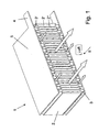
- the slots are also referred to as openings 2 ', the material arranged between the openings 2' as webs 2 "and the material arranged above and below the webs 2" as upper or lower side of the heating element 2.
- the heating element 2 consists of a plastic with PTC properties, in the present case of a polyolefin with soot particles, for which reason reference is also made below to the heating element 2 as a PTC element.
- the PTC element is produced by means of spraying; alternatively, other production methods, such as are known in particular from the production of plastics, are possible, such as, for example, extrusion or sintering.
- a plastic PTC element another suitable material with PTC properties can also be used.
- the height h K2 of the PTC element is presently 50 mm.
- the auxiliary heater 1 has two structures 3, each arranged above and below the PTC element and enlarging the heat-dissipating surface, which are each formed by a corrugated ridge with trapezoidal waves.
- the corrugated rib consist of an electrically conductive and highly thermally conductive metal sheet, in this case of a copper sheet.
- corrugated ribs are hereby arranged so that the peaks and valleys of the corrugated rib extend in the same direction as the openings 2 'of the heating element 2, so that the corrugated ribs also form through-openings 3' which are separated from one another by webs 3 "
- forming sheet metal has a material thickness, that is to say thickness d R2 , of 0.2 mm, in the present case the corrugated fin height h R2 being 5 mm.
- contact plates 5 are arranged on the side facing away from the PTC element side of the corrugated fin.
- the contact plates 5 are made of copper sheets.
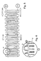
- an electrically conductive coating 6 is provided in each case on the surface, which is in contact with the corrugated fin (see FIG. 3). , which also has good heat-conducting properties. This ensures a relatively uniform current introduction from the corrugated rib into the PTC element.
- the coating 6 consists of a vapor deposited in the PVC process copper layer. The coating 6 is provided exclusively on the top and bottom of the PTC element, so that no short circuit occurs over the coating.
- the heater 1 is according to the first embodiment in which the motor vehicle air conditioner flowing through the air flow, indicated by arrows, in this case arranged after the heater, but the heater can also be located elsewhere in an air duct, for example. Shortly before Vents through which the air flows into the vehicle interior.
- the air to be heated is passed through both the openings 2 'in the heating element 2 and through the openings 3' formed by the corrugated fin.
- the current flow takes place, as shown in Fig. 3 by arrows, via the contact plate 5 to the corrugated fin, to the coating 6 and then to the PTC element, where the current flows through the top into the individual, between the openings 2 'formed webs 2 " The current then passes from the webs 2 "via the underside of the PTC element to the lower coating 6, to the corrugated fin and then to the lower contact sheet 5.
- the PTC element heats up in the corresponding area and regulates as a result of heating, so that less heat is generated in the corresponding area.
- the electrical resistance in the corresponding area increases, so that the current seeks another way, if possible.
- the thickness d is v2, which is formed by the top or bottom of the PTC element and the coating 6 provided thereon , as low as possible.
- the power densities of the surface of the individual webs 3 "of the PTC element are presently about 0.45 watts / cm 2 in an air flow with an air volume of more than 1 kg / min., And an air inlet temperature in the heater 1 of less than 40 ° C.
- the power densities under appropriate conditions based on the volume of the entire PTC element is presently about 4.0 watts / cm 3 .
- the contact sheet 5 is not arranged on the side of the structure 3 opposite the PTC element, but rather between the structure 3 and the coating 6 of the PTC element. Also in this case, the heat dissipating surface enlarging structure 3 conducts the heat generated at the entrance to the lands 3 "of the PTC element to the outside, so that an improved heating performance is effected. so that will not be discussed in detail.
- the coatings 6 of the top and bottom of the heating element 2 and the contact sheets 5 are dispensed with.
- the function of the contact sheets is taken over directly by the structures 3 enlarging the heat-dissipating surface, which are on the outside are provided with corresponding contact lugs for electrical contact.
- the current flow over the upper structure 3 is illustrated in FIG. 6 by arrows.
- an electrically conductive coating is provided on the top and bottom of the heating element, which correspond to the coatings 6 of the first embodiment and its first variant.
- the current input and - takes place - according to the second variant of the first embodiment - on the heat-dissipating surface enlarging Structures 3, so that, as compared with the previously described variant of the first embodiment, the entire top surface is supplied with more uniform power and derived from the entire bottom of the stream more evenly.
- an electric heater 1 is shown, which corresponds in its use to that of the first embodiment.
- the PTC heating element 2 is made of two different materials, the first material being used for the webs 2 "and the second material being used for the top and bottom, the first material being a plastic with PTC
- the second material is an electrically conductive plastic with low electrical resistance and without PTC effect
- the further construction of the additional heater 1 according to the second embodiment corresponds exactly to that of the first exemplary embodiment good electrical conductivity of the material used for the top and bottom of the heating element 2 and the missing PTC effect, the current is gleiichtex over the top of the webs 2 "fed and derived on the bottom of the webs 2" again.
- the coating derived to the corrugated fins where it is delivered to the corrugated air flowing through the air, so that in the corresponding areas of the webs 2 ", which are at least flowed around by air, so least cooled be, no current blocking the flow of heat accumulates, whereby the heating power of the auxiliary heater 1 is improved.
- the second embodiment eliminates the contact plate 5, whose Stromleitfunktion takes over by the heat-dissipating surface enlarging structures 3 (see Fig. 9).
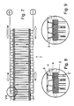
- FIG. 10 shows the auxiliary heater 1 according to the first exemplary embodiment, wherein the heating element 2 together with the heat-dissipating surface enlarging structures 3 and contact plates 5 are arranged in a housing 7.
- a mechanical tension is provided by means of a tension spring 8.
- the fixation in the housing 7 is thus purely mechanical.
- the entire interior of the housing 7 is traversed by air, so both the openings 2 'of the heating element 2 and the openings 3', which are formed by the heat-dissipating surface enlarging structures 3.
- FIG. 11 shows a heater 1 with two heating elements 2 clamped in a housing 7 by means of a tension spring 8, together with the structures 3 and contact plates 5 which enlarge the heat-dissipating surface.
- two contact sheets 5 are shown in the center, but in principle one of the contact sheets can also be dispensed with.
- the entire interior of the housing 7 is traversed by air, so again both the openings 2 'of the heating element 2 and the openings 3', which are formed by the heat-dissipating surface enlarging structures 3.
- a separate circuit of the two heating elements 2 possible, so that this heater 1, for example, can be used for two-zone air conditioning.
- FIGS. 12 and 13 show a glued auxiliary heater 1, the structure of the auxiliary heater 1 corresponding to that of the first exemplary embodiment.
- an electrically conductive adhesive 9 is provided between the coating 6 and the structure 3 enlarging the heat-dissipating surface and between the structure 3 enlarging the heat-dissipating surface and the contact sheet 5.
- contact points can be provided which are automatically freed of adhesive during joining as a result of the contact pressure, so that electrical contacting is ensured. This is particularly useful in a current feedthrough and / or a Stromzu- and -abtechnisch on the heat-dissipating surface enlarging structure.
- Fig. 14 shows the first variant of the first embodiment in glued embodiment, wherein an electrically conductive adhesive 9 is provided between the contact plate 5 and the coating 6.
- An insulating, but sufficiently good heat-dissipating adhesive 9 ' is provided between the contact plate 5 and the heat-dissipating surface enlarging structure 3, so that the structure 3 is at least usually not energized with sufficient adhesive film thickness.
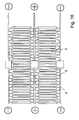
- FIG. 15 shows a glued auxiliary heater 1 with a continuous heating element 2.
- the structures 3 enlarging the heat-dissipating surface are interrupted, as are the contact plates 5, so that a separate circuit of the two heating element halves is possible.
- Fig. 16 shows another bonded heater 1 with two heating elements 2 arranged parallel to each other, again in the middle of the heating elements 2, the heat-dissipating surface enlarging structures 3, as well as the contact plates 5 are interrupted, so that a separate circuit of the two heating element halves, such as also the two heating elements 2 is possible.
- a heater 1 can be used, for example, in a four-zone air conditioning.
- the interconnection and control can be done in any known manner.
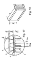
- FIG. 19 shows another possible attachment of structures 3 enlarging the heat-dissipating surface.
- the PTC element forming the heating element 2 is H-shaped and the structures 3 enlarging the heat-dissipating surface are clamped between the legs 2 "'of the PTC element.
- Such a mechanical fixation is sufficient as prefixing, the actual fixing and pressing of the heat-dissipating surface enlarging structures 3 to the PTC element takes place during the assembly in the housing, for example by means of tension springs ..
- a corresponding U-shaped configuration for the one-sided attachment of the heat-dissipating surface enlarging structure is of course also possible.
- short or continuous slots may be provided in extension of the region connecting the legs, into which the ends of the heat-dissipating surface-enlarging structures, which in this case are bent, are inserted for better fixation.
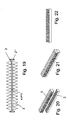
- FIGS. 20 to 23 show a third possibility of mechanical (pre) fixing of the heat-dissipating surface-enlarging structures 3 on the heating element 2.
- the wave-shaped profile of the heat-dissipating Surface enlarging structure 3 pushed together so that the openings 3 'are formed drop-shaped.
- the heating element 2 forming PTC element has on its upper side a plurality of grooves which correspond in profile to that of the heat-dissipating surface enlarging structure 3, wherein the grooves are wider in the lower region than in the upper region, so that an undercut is (indicated by the angle in Fig. 23).
- the underside of the heat-dissipating surface enlarging structure 3 is inserted into the grooves with slight elastic deformation during insertion and held therein by the undercut.
- the structure 3 which heats the heat-dissipating surface and the PTC element current can be supplied or discharged over a large area via the structure 3.
- the heat generated in the PTC element is dissipated rapidly over the structure 3 which increases the heat-dissipating surface, so that no heat build-up is generated in the transition region of the PTC element and thus the transition region does not automatically decelerate.
- the heating element 2 itself can be advantageously designed according to the previously described embodiments and their variants.
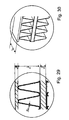
- Figures 24 to 28 show a fourth possibility of mechanical fixation of the heat-dissipating surface enlarging structures 3 on the heating element 2.
- the structure 3 is formed by a trapezoidal curved corrugated fin, wherein in the lower region of the oblique areas in each case present in a transversely extending slot is punched.
- the underside of the structure 3 is in turn inserted into the grooved top of the heating element 2 forming PTC element, wherein the grooves correspond in shape to the underside of the structure 3, but in the region of the slots of the structure 3 through tabs are formed (see Fig. 27 and 28), so that according to the above-described possibility of fixing an undercut of PTC element and structure 3 is provided, which ensures that the both parts are securely connected.
- the slots and noses do not have to extend over almost the entire width, but may - preferably in extension of each other - also be provided more slots and noses.
- a trapezoidal profile can be provided in this embodiment, a rectangular profile of
- the surface in contact with the structure 3 may be provided with an electrically conductive coating to ensure a large-area current transition, even if between structure 3 and heating element 2 in individual areas no large-scale plant due to dimensional variations and / or manufacturing errors is present.
- the structure and attachment of the heat-dissipating surface enlarging structure can be carried out according to the embodiments described above, so that dispenses with a detailed description of individual embodiments and reference is made to the above embodiments, which are to be modified accordingly.
- the structure which increases the heat-dissipating surface does not necessarily have to be formed as a corrugated fin. Rather, the structure may also be a forwarding from one PTC element to another PTC element, wherein preferably a plurality of such structures are provided between the PTC elements in order to allow a more uniform current input and output. In this case too, the heat dissipation from the critical areas improves the heating power of the PTC elements.
- the two contact plates 5 are provided with a plurality of nubs 5 'distributed over the entire surface of the contact plates 5, which points in one direction and are produced by means of forming the contact plate 5 ,
- the knobs 5 ' currently have an approximately truncated pyramidal shape, but other shapes, for example. Round, rectangular, wave-like, trapezoidal or meandering configurations are possible. Furthermore, the elevations may also extend in different directions.
- the function of the nubs 5 improves the adhesion of the PTC material on the contact plate 5, so that the electrical contact is significantly improved.
- the PTC material between the webs 2 "of the heating element 2 and the respective contact plate 5 (distance f, see FIG. 39) is as thin as possible, so that the heat can be released to the outside and the PTC material in the transition region not in consequence Power densities.
- each of the contact sheets 5 is molded into the PTC material, i. - Apart from the laterally protruding tabs 4 - completely surrounded by PTC material.
- additional structures may be arranged inside and / or outside to increase the heat-dissipating surface (not shown). These structures may also be partially cast in the PTC material.
- the thickness d of the webs 2 "of the heating element 2 is preferably less than 2 mm, in particular preferably 0.5 to 1.2 mm
- the aforementioned distance f should not be greater than the thickness d
- the distance of adjacent webs 2" e is preferably 1 to 4 mm.
- the maximum power density is less than 1 watt / cm 2 of the PTC surface, so that the dissipated power densities with a suitable design 0.3 to max. 0.7 watts / cm 2 .
- the coordination of the dimensions a, b and c is carried out accordingly, with a and c are linear in the power. If b is increased, although the heat-transferring surface increases as a result of the larger web length, but also decreases the power density due to the increased electrical resistance.
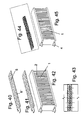
- the contact plate 5 is designed as a perforated plate, ie it is a plurality of openings 5 ", in this case through holes provided, which are completely filled during the pouring of the contact plate in the heating element 2 forming PTC material (see Fig. 43).
- the apertures 5 "need not have a circular shape, but rather any shapes are possible, such as serpentine or rectangular apertures, triangular or square apertures, etc. Variants are also possible according to which part or all of the material is cut into one or both Directions, for example, in the form of burrs, wherein the burrs are kept so small that they do not survive on the PTC material.
- the heater 1 according to this embodiment has the same external shape as the heater of the above-described embodiment.
- the heater 1 described below with reference to FIGS. 44 and 45 also has this shape, but instead of rigid contact plates, net-like contact elements with end-mounted contact paths 4 are provided, which correspond to the conventional contact lugs 4 of the embodiments described above.
- the net-like contact element is in turn completely surrounded by the PTC material.
- the network consists in the present case of copper wires, but also any other suitable material is possible, in particular aluminum.
- FIGS. 46 to 48 show an exemplary embodiment of an additional heater 1, which has different areas of the heating element 2.
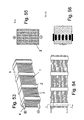
- FIGS. 49 to 52 show an exemplary embodiment and various variants according to which the PTC heating elements 2 are web-shaped, wherein a plurality of mutually parallel PTC heating elements are arranged side by side at equidistant intervals.
- the ends of the PTC heating elements are electrically contacted by means of contact elements 5, the contact elements 5 having grooves into which the ends of the PTC heating elements protrude.
- the ends of the PTC heating elements may be mechanically fixed, glued or injected in these grooves. Possibly.
- the PTC heating elements may also at least partially surround the contact elements 5, i. the contact elements 5 are injected.
- the PTC heating elements are preferably connected to one another (see FIG. 51), wherein this is also possible by subsequent encapsulation.
- a plurality of rows with PTC heating elements 2 can be arranged one above the other (see FIG. 52).
- a structure 3 enlarging the heat-dissipating surface is provided between individual block-shaped PTC heating elements 2, which is formed by a plurality of thin metal sheets arranged in parallel.
- the metal sheets are presently made of aluminum, preferably with a thickness of 0.06 to 0.4 mm, but other good metals or possibly other thermally conductive materials are suitable.
- the distances between two adjacent structures 3 is preferably 1 to 5 mm.
- the structures 3 are perforated in the region of the PTC heating elements 2, wherein the perforation in the present case is formed by oval openings.
- the hole width is preferably less than 3 mm, in particular between 1 and 1.5 mm.
- the current flow takes place, introduced or removed via the corresponding contact lug 4 and distributed through a top and a bottom arranged contact plate 5 through the entire PTC elements in one direction.
- the distance between the individual PTC heating elements 2 is preferably 10 to 40 mm.
- the externally arranged contact plates 5 can also be cast with the structures 3 in the heating elements 2.
- the sheet thickness of the contact sheets is preferably larger than that of the structures 3, preferably, the thickness of the contact sheets is 0.4 to 0.8 mm.
Landscapes
- Engineering & Computer Science (AREA)
- Physics & Mathematics (AREA)
- Thermal Sciences (AREA)
- Mechanical Engineering (AREA)
- Chemical & Material Sciences (AREA)
- Combustion & Propulsion (AREA)
- General Engineering & Computer Science (AREA)
- Air-Conditioning For Vehicles (AREA)
Priority Applications (1)
| Application Number | Priority Date | Filing Date | Title |
|---|---|---|---|
| EP20060290540 EP1839920B1 (fr) | 2006-03-31 | 2006-03-31 | Chauffage électrique pour un système de climatisation d'un véhicule |
Applications Claiming Priority (1)
| Application Number | Priority Date | Filing Date | Title |
|---|---|---|---|
| EP20060290540 EP1839920B1 (fr) | 2006-03-31 | 2006-03-31 | Chauffage électrique pour un système de climatisation d'un véhicule |
Publications (2)
| Publication Number | Publication Date |
|---|---|
| EP1839920A1 true EP1839920A1 (fr) | 2007-10-03 |
| EP1839920B1 EP1839920B1 (fr) | 2013-02-13 |
Family
ID=36693851
Family Applications (1)
| Application Number | Title | Priority Date | Filing Date |
|---|---|---|---|
| EP20060290540 Not-in-force EP1839920B1 (fr) | 2006-03-31 | 2006-03-31 | Chauffage électrique pour un système de climatisation d'un véhicule |
Country Status (1)
| Country | Link |
|---|---|
| EP (1) | EP1839920B1 (fr) |
Cited By (8)
| Publication number | Priority date | Publication date | Assignee | Title |
|---|---|---|---|---|
| WO2013053807A1 (fr) * | 2011-10-14 | 2013-04-18 | Valeo Systemes Thermiques | Module de chauffe isolé pour dispositif de chauffage additionnel |
| EP2288229A4 (fr) * | 2009-05-04 | 2016-07-13 | Lg Electronics Inc | Appareil chauffant |
| WO2018110193A1 (fr) * | 2016-12-13 | 2018-06-21 | 株式会社日本クライメイトシステムズ | Dispositif chauffant électrique de climatiseur de véhicule |
| CN108534347A (zh) * | 2018-05-18 | 2018-09-14 | 上海奉天电子股份有限公司 | 一种ptc电热装置的流道层结构 |
| WO2018215541A1 (fr) * | 2017-05-24 | 2018-11-29 | Webasto SE | Dispositif de chauffage et procédé de fabrication de ce dispositif |
| WO2019052763A1 (fr) * | 2017-09-12 | 2019-03-21 | Webasto SE | Dispositif de chauffage et procédé de fabrication de ce dispositif |
| DE102018200938A1 (de) | 2018-01-22 | 2019-07-25 | Ford Global Technologies, Llc | Temperiervorrichtung insbesondere zum Erwärmen eines Innenraums eines Fahrzeugs und/oder von Aggregaten des Fahrzeugs |
| CN112895846A (zh) * | 2021-02-02 | 2021-06-04 | 镇江海姆霍兹传热传动系统有限公司 | 电动车辆、电加热器及其电加热腔总成 |
Citations (7)
| Publication number | Priority date | Publication date | Assignee | Title |
|---|---|---|---|---|
| US4963716A (en) | 1987-05-01 | 1990-10-16 | Texas Instruments Incorporated | Vehicular air heater using PTC heater tablets associated with funnel heat exchanges |
| US5206476A (en) | 1991-09-30 | 1993-04-27 | General Motors Corporation | Supplementary automobile duct heater |
| EP0616486A1 (fr) | 1993-03-17 | 1994-09-21 | Texas Instruments Incorporated | Appareil de chauffage et procédé pour chauffer un courant de fluide |
| JP3274234B2 (ja) | 1992-06-23 | 2002-04-15 | ダーフィト・ウント・バーダー・−デー・ベー・カー−・スペツィアルファブリーク・エレクトリシャー・アパラーテ・ウント・ハイツヴィダーステーンデ・ゲゼルシャフト・ミット・ベシュレンクテル・ハフツング | ラジエータ |
| US20040252986A1 (en) | 2003-06-10 | 2004-12-16 | Hitoshi Ito | Electrical heater, heating heat exchanger and vehicle air conditioner |
| DE102004045668A1 (de) | 2003-10-31 | 2005-06-30 | Behr Gmbh & Co. Kg | Elektrisch beheizbare Kunststoffmatrix |
| EP1574791A1 (fr) | 2004-03-09 | 2005-09-14 | CEBI S.p.A. | Dispositif de chauffage électrique pour système de ventilation d'automobile |
-
2006
- 2006-03-31 EP EP20060290540 patent/EP1839920B1/fr not_active Not-in-force
Patent Citations (8)
| Publication number | Priority date | Publication date | Assignee | Title |
|---|---|---|---|---|
| US4963716A (en) | 1987-05-01 | 1990-10-16 | Texas Instruments Incorporated | Vehicular air heater using PTC heater tablets associated with funnel heat exchanges |
| US5206476A (en) | 1991-09-30 | 1993-04-27 | General Motors Corporation | Supplementary automobile duct heater |
| JP3274234B2 (ja) | 1992-06-23 | 2002-04-15 | ダーフィト・ウント・バーダー・−デー・ベー・カー−・スペツィアルファブリーク・エレクトリシャー・アパラーテ・ウント・ハイツヴィダーステーンデ・ゲゼルシャフト・ミット・ベシュレンクテル・ハフツング | ラジエータ |
| EP0616486A1 (fr) | 1993-03-17 | 1994-09-21 | Texas Instruments Incorporated | Appareil de chauffage et procédé pour chauffer un courant de fluide |
| US20040252986A1 (en) | 2003-06-10 | 2004-12-16 | Hitoshi Ito | Electrical heater, heating heat exchanger and vehicle air conditioner |
| DE102004027687A1 (de) | 2003-06-10 | 2004-12-30 | Denso Corp., Kariya | Elektrische Heizvorrichtung, heizender Wärmetauscher und Fahrzeug-Klimaanlage |
| DE102004045668A1 (de) | 2003-10-31 | 2005-06-30 | Behr Gmbh & Co. Kg | Elektrisch beheizbare Kunststoffmatrix |
| EP1574791A1 (fr) | 2004-03-09 | 2005-09-14 | CEBI S.p.A. | Dispositif de chauffage électrique pour système de ventilation d'automobile |
Cited By (16)
| Publication number | Priority date | Publication date | Assignee | Title |
|---|---|---|---|---|
| EP2288229A4 (fr) * | 2009-05-04 | 2016-07-13 | Lg Electronics Inc | Appareil chauffant |
| WO2013053807A1 (fr) * | 2011-10-14 | 2013-04-18 | Valeo Systemes Thermiques | Module de chauffe isolé pour dispositif de chauffage additionnel |
| CN103874890A (zh) * | 2011-10-14 | 2014-06-18 | 法雷奥热系统公司 | 用于补充加热装置的绝缘的加热模块 |
| US20140231411A1 (en) * | 2011-10-14 | 2014-08-21 | Valeo Systemes Thermiques | Insulated Heating Module For A Supplemental Heating Device |
| US9539881B2 (en) | 2011-10-14 | 2017-01-10 | Valeo Systemes Thermiques | Insulated heating module for a supplemental heating device |
| WO2018110193A1 (fr) * | 2016-12-13 | 2018-06-21 | 株式会社日本クライメイトシステムズ | Dispositif chauffant électrique de climatiseur de véhicule |
| WO2018215196A1 (fr) * | 2017-05-24 | 2018-11-29 | Webasto SE | Appareil de chauffage d'air |
| WO2018215541A1 (fr) * | 2017-05-24 | 2018-11-29 | Webasto SE | Dispositif de chauffage et procédé de fabrication de ce dispositif |
| WO2018215623A1 (fr) * | 2017-05-24 | 2018-11-29 | Webasto SE | Dispositif de chauffage de fluide et procédé de fabrication de ce dispositif |
| CN110662926A (zh) * | 2017-05-24 | 2020-01-07 | 韦巴斯托股份公司 | 加热器和用于制造加热器的方法 |
| CN110678343A (zh) * | 2017-05-24 | 2020-01-10 | 韦巴斯托股份公司 | 电加热器 |
| CN110678704A (zh) * | 2017-05-24 | 2020-01-10 | 韦巴斯托股份公司 | 流体加热器和用于制造流体加热器的方法 |
| WO2019052763A1 (fr) * | 2017-09-12 | 2019-03-21 | Webasto SE | Dispositif de chauffage et procédé de fabrication de ce dispositif |
| DE102018200938A1 (de) | 2018-01-22 | 2019-07-25 | Ford Global Technologies, Llc | Temperiervorrichtung insbesondere zum Erwärmen eines Innenraums eines Fahrzeugs und/oder von Aggregaten des Fahrzeugs |
| CN108534347A (zh) * | 2018-05-18 | 2018-09-14 | 上海奉天电子股份有限公司 | 一种ptc电热装置的流道层结构 |
| CN112895846A (zh) * | 2021-02-02 | 2021-06-04 | 镇江海姆霍兹传热传动系统有限公司 | 电动车辆、电加热器及其电加热腔总成 |
Also Published As
| Publication number | Publication date |
|---|---|
| EP1839920B1 (fr) | 2013-02-13 |
Similar Documents
| Publication | Publication Date | Title |
|---|---|---|
| EP1839920B1 (fr) | Chauffage électrique pour un système de climatisation d'un véhicule | |
| EP2744034B1 (fr) | Agencement d'échangeur thermique | |
| WO2006012963A1 (fr) | Dispositif de chauffage comportant un element chauffant, destine notamment a un vehicule a moteur | |
| EP1772684A2 (fr) | Module chauffant électrique pour chauffer un flux d'air, notamment pour chauffer et aérer des chaises | |
| EP1714810B1 (fr) | Chauffage supplémentaire électrique pour un système de climatisation d'un véhicule | |
| WO2009153012A1 (fr) | Dispositif pour le refroidissement d'une batterie de véhicule | |
| EP1933598B1 (fr) | Chauffage ou chauffage supplémentaire électrique, en particulier pour un système de chauffage ou climatisation d'un véhicule | |
| WO2009087106A1 (fr) | Module à lamelles d'échangeur thermique, échangeur thermique et module de chauffage électrique | |
| DE102010038781A1 (de) | Kombi-Wärmetauscher und Verfahren zur Herstellung eines Kombi-Wärmetauschers | |
| EP1935684B1 (fr) | Chauffage électrique ou chauffage, en particulier pour un climatiseur ou une installation de chauffage d'un véhicule automobile | |
| WO2003098124A1 (fr) | Echangeur de chaleur, destine en particulier a une installation de chauffage ou de climatisation d'un vehicule automobile | |
| EP2145783B1 (fr) | Chauffage de véhicule | |
| EP1926346B1 (fr) | Dispositif de chauffage électrique, en particulier de véhicules | |
| DE102010033309A1 (de) | Wärmetauscher-Lamellenmodul, Wärmetauscher und elektrisches Heizmodul | |
| EP1933597B1 (fr) | Chauffage ou chauffage supplémentaire électrique, en particulier pour un système de chauffage ou climatisation d'un véhicule | |
| DE202017102436U1 (de) | Wärmetauscher mit Mikrokanal-Struktur oder Flügelrohr-Struktur | |
| DE202010011016U1 (de) | Elektrisches Heizmodul mit PTC-Element zum elektrischen Erwärmen eines Luftstroms | |
| DE102010033310B4 (de) | Elektrisches Heizmodul mit PTC-Element zum elektrischen Erwärmen eines Luftstroms | |
| EP3553450B1 (fr) | Unité d'échangeur de chaleur | |
| EP1687572B1 (fr) | Echanger de chaleur, en particulier pour un systeme de chauffage ou de climatisation d'un vehicule à moteur | |
| DE102006025320A1 (de) | Wärmetauscher, insbesondere für eine Heizungs- oder Klimaanlage eines Kraftfahrzeugs | |
| EP1445553B1 (fr) | Echangeur de chaleur | |
| EP2151639B1 (fr) | Caloporteur | |
| EP1885159B1 (fr) | Ensemble de chauffage électrique, notamment pour véhicule automobile | |
| EP1457368A1 (fr) | Echangeur de chaleur avec chauffage électrique supplémentaire intégré |
Legal Events
| Date | Code | Title | Description |
|---|---|---|---|
| PUAI | Public reference made under article 153(3) epc to a published international application that has entered the european phase |
Free format text: ORIGINAL CODE: 0009012 |
|
| AK | Designated contracting states |
Kind code of ref document: A1 Designated state(s): AT BE BG CH CY CZ DE DK EE ES FI FR GB GR HU IE IS IT LI LT LU LV MC NL PL PT RO SE SI SK TR |
|
| AX | Request for extension of the european patent |
Extension state: AL BA HR MK YU |
|
| 17P | Request for examination filed |
Effective date: 20080403 |
|
| 17Q | First examination report despatched |
Effective date: 20080508 |
|
| AKX | Designation fees paid |
Designated state(s): AT BE BG CH CY CZ DE DK EE ES FI FR GB GR HU IE IS IT LI LT LU LV MC NL PL PT RO SE SI SK TR |
|
| REG | Reference to a national code |
Ref country code: DE Ref legal event code: R079 Ref document number: 502006012494 Country of ref document: DE Free format text: PREVIOUS MAIN CLASS: B60H0001000000 Ipc: B60H0001220000 |
|
| RIC1 | Information provided on ipc code assigned before grant |
Ipc: B60H 1/00 20060101ALI20120620BHEP Ipc: F24H 3/04 20060101ALI20120620BHEP Ipc: F24H 9/18 20060101ALI20120620BHEP Ipc: B60H 1/22 20060101AFI20120620BHEP |
|
| GRAP | Despatch of communication of intention to grant a patent |
Free format text: ORIGINAL CODE: EPIDOSNIGR1 |
|
| GRAS | Grant fee paid |
Free format text: ORIGINAL CODE: EPIDOSNIGR3 |
|
| GRAA | (expected) grant |
Free format text: ORIGINAL CODE: 0009210 |
|
| AK | Designated contracting states |
Kind code of ref document: B1 Designated state(s): AT BE BG CH CY CZ DE DK EE ES FI FR GB GR HU IE IS IT LI LT LU LV MC NL PL PT RO SE SI SK TR |
|
| REG | Reference to a national code |
Ref country code: GB Ref legal event code: FG4D Free format text: NOT ENGLISH Ref country code: DE Ref legal event code: R081 Ref document number: 502006012494 Country of ref document: DE Owner name: MAHLE INTERNATIONAL GMBH, DE Free format text: FORMER OWNERS: BEHR GMBH & CO. KG, 70469 STUTTGART, DE; BEHR FRANCE ROUFFACH S.A.S., ROUFFACH, FR |
|
| REG | Reference to a national code |
Ref country code: AT Ref legal event code: REF Ref document number: 596273 Country of ref document: AT Kind code of ref document: T Effective date: 20130215 |
|
| REG | Reference to a national code |
Ref country code: IE Ref legal event code: FG4D Free format text: LANGUAGE OF EP DOCUMENT: GERMAN |
|
| REG | Reference to a national code |
Ref country code: DE Ref legal event code: R096 Ref document number: 502006012494 Country of ref document: DE Effective date: 20130411 |
|
| REG | Reference to a national code |
Ref country code: NL Ref legal event code: VDEP Effective date: 20130213 |
|
| REG | Reference to a national code |
Ref country code: LT Ref legal event code: MG4D |
|
| PG25 | Lapsed in a contracting state [announced via postgrant information from national office to epo] |
Ref country code: ES Free format text: LAPSE BECAUSE OF FAILURE TO SUBMIT A TRANSLATION OF THE DESCRIPTION OR TO PAY THE FEE WITHIN THE PRESCRIBED TIME-LIMIT Effective date: 20130524 Ref country code: IS Free format text: LAPSE BECAUSE OF FAILURE TO SUBMIT A TRANSLATION OF THE DESCRIPTION OR TO PAY THE FEE WITHIN THE PRESCRIBED TIME-LIMIT Effective date: 20130613 Ref country code: LT Free format text: LAPSE BECAUSE OF FAILURE TO SUBMIT A TRANSLATION OF THE DESCRIPTION OR TO PAY THE FEE WITHIN THE PRESCRIBED TIME-LIMIT Effective date: 20130213 Ref country code: BG Free format text: LAPSE BECAUSE OF FAILURE TO SUBMIT A TRANSLATION OF THE DESCRIPTION OR TO PAY THE FEE WITHIN THE PRESCRIBED TIME-LIMIT Effective date: 20130513 Ref country code: SE Free format text: LAPSE BECAUSE OF FAILURE TO SUBMIT A TRANSLATION OF THE DESCRIPTION OR TO PAY THE FEE WITHIN THE PRESCRIBED TIME-LIMIT Effective date: 20130213 |
|
| PG25 | Lapsed in a contracting state [announced via postgrant information from national office to epo] |
Ref country code: PT Free format text: LAPSE BECAUSE OF FAILURE TO SUBMIT A TRANSLATION OF THE DESCRIPTION OR TO PAY THE FEE WITHIN THE PRESCRIBED TIME-LIMIT Effective date: 20130613 Ref country code: FI Free format text: LAPSE BECAUSE OF FAILURE TO SUBMIT A TRANSLATION OF THE DESCRIPTION OR TO PAY THE FEE WITHIN THE PRESCRIBED TIME-LIMIT Effective date: 20130213 Ref country code: PL Free format text: LAPSE BECAUSE OF FAILURE TO SUBMIT A TRANSLATION OF THE DESCRIPTION OR TO PAY THE FEE WITHIN THE PRESCRIBED TIME-LIMIT Effective date: 20130213 Ref country code: GR Free format text: LAPSE BECAUSE OF FAILURE TO SUBMIT A TRANSLATION OF THE DESCRIPTION OR TO PAY THE FEE WITHIN THE PRESCRIBED TIME-LIMIT Effective date: 20130514 Ref country code: LV Free format text: LAPSE BECAUSE OF FAILURE TO SUBMIT A TRANSLATION OF THE DESCRIPTION OR TO PAY THE FEE WITHIN THE PRESCRIBED TIME-LIMIT Effective date: 20130213 Ref country code: SI Free format text: LAPSE BECAUSE OF FAILURE TO SUBMIT A TRANSLATION OF THE DESCRIPTION OR TO PAY THE FEE WITHIN THE PRESCRIBED TIME-LIMIT Effective date: 20130213 |
|
| BERE | Be: lapsed |
Owner name: BEHR FRANCE ROUFFACH SAS Effective date: 20130331 Owner name: BEHR G.M.B.H. & CO. KG Effective date: 20130331 |
|
| PG25 | Lapsed in a contracting state [announced via postgrant information from national office to epo] |
Ref country code: NL Free format text: LAPSE BECAUSE OF FAILURE TO SUBMIT A TRANSLATION OF THE DESCRIPTION OR TO PAY THE FEE WITHIN THE PRESCRIBED TIME-LIMIT Effective date: 20130213 Ref country code: CZ Free format text: LAPSE BECAUSE OF FAILURE TO SUBMIT A TRANSLATION OF THE DESCRIPTION OR TO PAY THE FEE WITHIN THE PRESCRIBED TIME-LIMIT Effective date: 20130213 Ref country code: EE Free format text: LAPSE BECAUSE OF FAILURE TO SUBMIT A TRANSLATION OF THE DESCRIPTION OR TO PAY THE FEE WITHIN THE PRESCRIBED TIME-LIMIT Effective date: 20130213 Ref country code: MC Free format text: LAPSE BECAUSE OF NON-PAYMENT OF DUE FEES Effective date: 20130331 Ref country code: DK Free format text: LAPSE BECAUSE OF FAILURE TO SUBMIT A TRANSLATION OF THE DESCRIPTION OR TO PAY THE FEE WITHIN THE PRESCRIBED TIME-LIMIT Effective date: 20130213 Ref country code: SK Free format text: LAPSE BECAUSE OF FAILURE TO SUBMIT A TRANSLATION OF THE DESCRIPTION OR TO PAY THE FEE WITHIN THE PRESCRIBED TIME-LIMIT Effective date: 20130213 Ref country code: RO Free format text: LAPSE BECAUSE OF FAILURE TO SUBMIT A TRANSLATION OF THE DESCRIPTION OR TO PAY THE FEE WITHIN THE PRESCRIBED TIME-LIMIT Effective date: 20130213 |
|
| REG | Reference to a national code |
Ref country code: CH Ref legal event code: PL |
|
| PLBE | No opposition filed within time limit |
Free format text: ORIGINAL CODE: 0009261 |
|
| STAA | Information on the status of an ep patent application or granted ep patent |
Free format text: STATUS: NO OPPOSITION FILED WITHIN TIME LIMIT |
|
| PG25 | Lapsed in a contracting state [announced via postgrant information from national office to epo] |
Ref country code: IT Free format text: LAPSE BECAUSE OF FAILURE TO SUBMIT A TRANSLATION OF THE DESCRIPTION OR TO PAY THE FEE WITHIN THE PRESCRIBED TIME-LIMIT Effective date: 20130213 |
|
| REG | Reference to a national code |
Ref country code: IE Ref legal event code: MM4A |
|
| 26N | No opposition filed |
Effective date: 20131114 |
|
| GBPC | Gb: european patent ceased through non-payment of renewal fee |
Effective date: 20130513 |
|
| PG25 | Lapsed in a contracting state [announced via postgrant information from national office to epo] |
Ref country code: LI Free format text: LAPSE BECAUSE OF NON-PAYMENT OF DUE FEES Effective date: 20130331 Ref country code: BE Free format text: LAPSE BECAUSE OF NON-PAYMENT OF DUE FEES Effective date: 20130331 Ref country code: IE Free format text: LAPSE BECAUSE OF NON-PAYMENT OF DUE FEES Effective date: 20130331 Ref country code: CH Free format text: LAPSE BECAUSE OF NON-PAYMENT OF DUE FEES Effective date: 20130331 |
|
| REG | Reference to a national code |
Ref country code: DE Ref legal event code: R097 Ref document number: 502006012494 Country of ref document: DE Effective date: 20131114 |
|
| PG25 | Lapsed in a contracting state [announced via postgrant information from national office to epo] |
Ref country code: GB Free format text: LAPSE BECAUSE OF NON-PAYMENT OF DUE FEES Effective date: 20130513 |
|
| REG | Reference to a national code |
Ref country code: AT Ref legal event code: MM01 Ref document number: 596273 Country of ref document: AT Kind code of ref document: T Effective date: 20130331 |
|
| PG25 | Lapsed in a contracting state [announced via postgrant information from national office to epo] |
Ref country code: AT Free format text: LAPSE BECAUSE OF NON-PAYMENT OF DUE FEES Effective date: 20130331 |
|
| PG25 | Lapsed in a contracting state [announced via postgrant information from national office to epo] |
Ref country code: TR Free format text: LAPSE BECAUSE OF FAILURE TO SUBMIT A TRANSLATION OF THE DESCRIPTION OR TO PAY THE FEE WITHIN THE PRESCRIBED TIME-LIMIT Effective date: 20130213 Ref country code: CY Free format text: LAPSE BECAUSE OF FAILURE TO SUBMIT A TRANSLATION OF THE DESCRIPTION OR TO PAY THE FEE WITHIN THE PRESCRIBED TIME-LIMIT Effective date: 20130213 |
|
| PG25 | Lapsed in a contracting state [announced via postgrant information from national office to epo] |
Ref country code: HU Free format text: LAPSE BECAUSE OF FAILURE TO SUBMIT A TRANSLATION OF THE DESCRIPTION OR TO PAY THE FEE WITHIN THE PRESCRIBED TIME-LIMIT; INVALID AB INITIO Effective date: 20060331 Ref country code: LU Free format text: LAPSE BECAUSE OF NON-PAYMENT OF DUE FEES Effective date: 20130331 |
|
| REG | Reference to a national code |
Ref country code: DE Ref legal event code: R082 Ref document number: 502006012494 Country of ref document: DE Representative=s name: GRAUEL, ANDREAS, DIPL.-PHYS. DR. RER. NAT., DE Ref country code: DE Ref legal event code: R081 Ref document number: 502006012494 Country of ref document: DE Owner name: MAHLE INTERNATIONAL GMBH, DE Free format text: FORMER OWNERS: BEHR FRANCE ROUFFACH SAS, ROUFFACH, FR; BEHR GMBH & CO. KG, 70469 STUTTGART, DE |
|
| REG | Reference to a national code |
Ref country code: FR Ref legal event code: PLFP Year of fee payment: 11 |
|
| REG | Reference to a national code |
Ref country code: FR Ref legal event code: PLFP Year of fee payment: 12 |
|
| REG | Reference to a national code |
Ref country code: FR Ref legal event code: PLFP Year of fee payment: 13 |
|
| PGFP | Annual fee paid to national office [announced via postgrant information from national office to epo] |
Ref country code: DE Payment date: 20180329 Year of fee payment: 13 |
|
| REG | Reference to a national code |
Ref country code: DE Ref legal event code: R119 Ref document number: 502006012494 Country of ref document: DE |
|
| PG25 | Lapsed in a contracting state [announced via postgrant information from national office to epo] |
Ref country code: DE Free format text: LAPSE BECAUSE OF NON-PAYMENT OF DUE FEES Effective date: 20191001 |
|
| PGFP | Annual fee paid to national office [announced via postgrant information from national office to epo] |
Ref country code: FR Payment date: 20200401 Year of fee payment: 15 |
|
| PG25 | Lapsed in a contracting state [announced via postgrant information from national office to epo] |
Ref country code: FR Free format text: LAPSE BECAUSE OF NON-PAYMENT OF DUE FEES Effective date: 20210331 |