EP1839883A1 - Method and device for printing on plate-like objects - Google Patents
Method and device for printing on plate-like objects Download PDFInfo
- Publication number
- EP1839883A1 EP1839883A1 EP06004713A EP06004713A EP1839883A1 EP 1839883 A1 EP1839883 A1 EP 1839883A1 EP 06004713 A EP06004713 A EP 06004713A EP 06004713 A EP06004713 A EP 06004713A EP 1839883 A1 EP1839883 A1 EP 1839883A1
- Authority
- EP
- European Patent Office
- Prior art keywords
- module
- printed
- printing
- modules
- pretreatment
- Prior art date
- Legal status (The legal status is an assumption and is not a legal conclusion. Google has not performed a legal analysis and makes no representation as to the accuracy of the status listed.)
- Granted
Links
Images
Classifications
-
- B—PERFORMING OPERATIONS; TRANSPORTING
- B41—PRINTING; LINING MACHINES; TYPEWRITERS; STAMPS
- B41J—TYPEWRITERS; SELECTIVE PRINTING MECHANISMS, i.e. MECHANISMS PRINTING OTHERWISE THAN FROM A FORME; CORRECTION OF TYPOGRAPHICAL ERRORS
- B41J3/00—Typewriters or selective printing or marking mechanisms characterised by the purpose for which they are constructed
- B41J3/407—Typewriters or selective printing or marking mechanisms characterised by the purpose for which they are constructed for marking on special material
-
- B—PERFORMING OPERATIONS; TRANSPORTING
- B41—PRINTING; LINING MACHINES; TYPEWRITERS; STAMPS
- B41J—TYPEWRITERS; SELECTIVE PRINTING MECHANISMS, i.e. MECHANISMS PRINTING OTHERWISE THAN FROM A FORME; CORRECTION OF TYPOGRAPHICAL ERRORS
- B41J11/00—Devices or arrangements of selective printing mechanisms, e.g. ink-jet printers or thermal printers, for supporting or handling copy material in sheet or web form
- B41J11/0015—Devices or arrangements of selective printing mechanisms, e.g. ink-jet printers or thermal printers, for supporting or handling copy material in sheet or web form for treating before, during or after printing or for uniform coating or laminating the copy material before or after printing
-
- B—PERFORMING OPERATIONS; TRANSPORTING
- B41—PRINTING; LINING MACHINES; TYPEWRITERS; STAMPS
- B41J—TYPEWRITERS; SELECTIVE PRINTING MECHANISMS, i.e. MECHANISMS PRINTING OTHERWISE THAN FROM A FORME; CORRECTION OF TYPOGRAPHICAL ERRORS
- B41J3/00—Typewriters or selective printing or marking mechanisms characterised by the purpose for which they are constructed
- B41J3/407—Typewriters or selective printing or marking mechanisms characterised by the purpose for which they are constructed for marking on special material
- B41J3/4073—Printing on three-dimensional objects not being in sheet or web form, e.g. spherical or cubic objects
Definitions
- the invention relates to a method and apparatus for printing plate-shaped workpieces, in which a portion of the plate-shaped workpiece is printed with a desired pattern, in particular by means of ink-jet printing.
- Plate-shaped workpieces which are used, for example, as components for furniture, are often provided after cutting and the size or shaping process on a narrow side with suitable materials such as edges, webs or films of engineering polymers (ABS, PP, PVC) or wood veneer strips. This measure is used, for example, to achieve an intended appearance or feel or to act as protection against mechanical stress or to prevent the ingress of moisture.
- the plate-shaped workpieces considered here may, for example, be chipboard, plywood, fiber and other wood-based panels or, for example, plasterboard and gypsum fiberboard or, for example, laminate and rigid foam panels or lightweight or sandwich panels.
- the narrow sides of plate-shaped workpieces considered in this case are narrow sides closed by a material suitable for this purpose plate-shaped workpieces, for example. Run as a plastic sheet, profile or foil or act as a wood strip or veneer or other natural materials or as sealed with paint, UV varnish or sealant surface.
- a method and an apparatus for printing such plate-shaped workpieces by means of ink-jet printing is, for example, in DE 100 31 030 A1 disclosed.
- the known printing method or the known printing device leads to a limited quality and durability of the applied print image.
- the invention is based on the finding that in the case of plate-shaped workpieces of the type in question for closing the narrow side or other surface sections leads to a pronounced degree of contamination of the surface, which impairs the quality and durability of the subsequently applied print image.
- dust particles, lubricants, adhesive residues, chips, Hand sweat, fingerprints, scratches and other dirt or damage are applied to the surface.
- the technical polymers used here for example, behave in terms of water repellency in their surface properties and are thus difficult to wet.
- a portion of a plate-shaped workpiece to be printed is first subjected to one or more pretreatment steps which are selected from a) pre-cleaning, b) degreasing, c) improving the adhesion and wetting properties and d) reduction the electrostatic charge.
- pretreatment steps which are selected from a) pre-cleaning, b) degreasing, c) improving the adhesion and wetting properties and d) reduction the electrostatic charge.
- the pretreatment steps are selected selectively depending on the material and / or the surface condition of the section to be printed. As a result, it is not always necessary to carry out all the aforementioned pretreatment steps, but it may be sufficient to carry out only one or a few pretreatment steps matched to the respective material or the respective surface finish, without having to compromise on the quality and durability of the printed image obtained. Although this selection can also be made manually, for example by an operator, it is preferred within the scope of the invention for the selective selection to be controlled electronically, for example by means of a corresponding control device.
- the method according to the invention can be carried out on a stationary workpiece, for example in a machining center which is equipped to carry out the various pretreatment steps.
- a machining center which is equipped to carry out the various pretreatment steps.
- the pretreatment steps and / or the printing are carried out in a continuous process.
- An apparatus according to the invention for carrying out the method according to the invention is the subject matter of independent claim 9.
- This apparatus is characterized by having one or more pretreatment modules selected from a pre-cleaning module, a degreasing module, a module for improving the adhesion and use properties, and a module for reducing the electrostatic charge.
- the pretreatment modules can be set into operation selectively as a function of the material and / or the surface condition of the section to be printed. This makes it possible that the operation of the device according to the invention can be selectively adjusted to the material and / or the surface condition of the section to be printed, so that for each plate-shaped workpiece an optimal Pre-cleaning result and thus also an optimal print image results.
- the pretreatment modules and preferably also the pressure device and / or the conveyor device are connected to a control device. This makes it possible that the device according to the invention can be completely automated and thus work quickly and economically, without having to compromise on the quality or durability of the printed image obtained.
- the device according to the invention may be, for example, a so-called stationary machine (for example a machining center) or a so-called pass-through machine.
- the workpieces to be printed are arranged stationary, and the conveyor moves the respective pre-treatment modules or the printing device with respect to the workpieces to be printed.
- the pretreatment modules and the printing device are arranged stationary, and the workpieces to be printed are moved past these pretreatment modules or the printing device by means of the conveyor.
- combinations of both concepts are also possible, for example, pretreatment modules operating in the run and a printing device operating as a stationary machine.
- the conveyor according to a development of the present invention is a continuous conveyor which conveys the plate-shaped workpieces to be printed past the pre-treatment modules and / or the printing device.
- the device according to the invention can furthermore be constructed by a plurality of different or separate machine units, for example by providing a separate machine unit for each pretreatment module and for the printing device, wherein these units can also be spatially separated.
- pretreatment modules are provided on a machine arrangement, since this simplifies the operation of the device according to the invention and improves the pre-cleaning result.
- the printing device and / or the conveying device are provided on this machine arrangement.
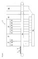
- the figure shows a schematic side view of a preferred embodiment of the device according to the invention.
- a pretreatment and printing apparatus 1 as a preferred embodiment of the present invention is schematically shown in a side view.
- the device 1 is used for printing plate-shaped workpieces 2, which consist at least partially of wood, wood materials, wood substitutes, plastics, lightweight materials or the like, as they are often used for example in furniture manufacturing.
- the device 1 in the present embodiment comprises a plurality of Pre-treatment modules 10, 20, 30, 40 or sub-modules, which will be discussed in more detail below.
- the present invention is not limited to the arrangement shown. Rather, a device according to the invention can also have only one or several pretreatment modules, for example if the device is designed only for a specific type of plate-shaped workpieces to be printed.
- the order of the individual pretreatment modules or sub-modules is not limited to the arrangement shown in Fig. 1, although this is a preferred arrangement or order.
- the device 1 comprises a printing device 50, which is particularly preferably an ink-jet printing device.
- an ink-jet printing device is meant an ink printing device in which ink drops are ejected by the drop-on-demand method, i. the printing device ejects a desired sequence of ink drops in response to a print command.
- printheads are used which have piezoelectric elements or thermally work (“bubble-jet").
- bubble-jet thermally work
- the device according to the invention further comprises a conveying device 60, which in the present embodiment is designed as a linear conveyor, for example as a chain or belt conveyor.
- a conveying device 60 On this conveyor 60, plate-shaped workpieces 2 can be conveyed past or through the pretreatment modules 10, 20, 30, 40 or the corresponding submodules as well as the pressure device 50.
- a section 4 of the plate-shaped workpiece 2 to be printed and pretreated is the pretreatment modules 10, 20, 30, 40 or facing the printing device 50, ie the section 4 is arranged in Fig. 1 on the side facing away from the viewer side.
- the pretreatment modules 10, 20, 30, 40 or their submodules according to the present embodiment will now be explained in more detail.
- the apparatus 1 initially comprises a pre-cleaning module 10, which in the present embodiment comprises three sub-modules, namely a scrubbing module 11, an abrasive module 12 and a CO 2 scrubber cleaning module 13.
- the scrub module can operate mechanically-chemically, for example by having filament fiber brushes filled with diamond dust to which an antistatic and cleaning agent is supplied during operation. In this case, the brushing at the same time a grinding and cleaning and antistatic treatment is achieved.
- This brush module 11 is particularly well suited for hard surfaces or surfaces where an increase in roughness is desired. These include, for example, wood veneers or painted surfaces.
- the scrubbing module 11 or the grinding module 12 can be followed by a further cleaning device (for example a brush) with built-in suction, although this is not shown in the figure.
- a cleaning of the surface by means of the CO 2 -Schneestrahlmaniasmoduls 13 is useful.
- the cleaning with CO 2 irradiation is based on several physical and chemical effects, whereby their thermal, chemical and mechanical effect is exploited.
- the process converts liquid CO 2 provided , for example, into CO 2 bottles by thermodynamic and physical Processes into compressed, solid CO 2 snow particles.
- These CO 2 snow particles are produced using a suitable process and nozzle technology in a specific size. They are added to a compressed air stream in a multi-stage mixing chamber using a jet nozzle. In doing so, a homogeneous free jet is created with which surfaces can be cleaned and pretreated.
- the thermal effect of the CO 2 snow jet causes shock freezing of the surface contamination. Due to the different coefficients of thermal expansion of the surface and the surface, the use of CO 2 snow blasting leads to embrittlement of the contamination. This makes them easy to detach from the surface. Furthermore, the use of compressed air as transport gas and the design of the irradiation nozzle to mechanical actions, which remove the embrittled contaminants from the surface. The sublimation expansion of CO 2 also contributes to this, which contributes to the detachment and removal of the contamination from the surface.
- the chemical action of the CO 2 snow jet further consists of surface contamination removal processes caused by the carbon dioxide gaseous after the sublimation process. This has a further positive influence on the removal of surface contaminants and supports the removal of the contamination.
- CO 2 snow jet modules or devices are available, for example, from Cryosnow GmbH, Zitadellenweg 20 E, D-13599 Berlin under the name CS-4.
- the CO 2 snow blasting has the advantage of non-contact and thus not abrasive to bring about a cleaning. Therefore, the CO 2 snow blasting is suitable For example, especially good for plastic-based surfaces. Furthermore, the CO 2 snow blasting is particularly well suited for contaminated with fats, oils or other organic substances surfaces, since these contaminants shock-frozen due to the low temperatures of CO 2 and embrittle and by means of a suction device (not shown) can be sucked.
- the device 1 further comprises a degreasing module 20.
- the degreasing module 20 is formed in the present embodiment by an electro-mechanical wiping module, which is adapted to apply a degreasing agent on the printed portion 4 and wipe.
- a degreasing agent for example, acetone, methyl ethyl ketone (MEK), isopropanol, ethanol or the like can be used.
- the wiping module comprises a wiping agent, for example in the form of a suitable tile, cloth or other liquid-absorbent aid, which is moistened by means of a spray nozzle.
- the wiping agent can be brought into direct contact with the surface 4 in order to effect the mechanical-chemical degreasing process.
- degreasing module 20 or its wiping module is particularly suitable, for example, for plastic-based surfaces such as plastic edges or foils.
- the apparatus 1 further comprises a module 30 for improving the adhesion and wetting properties, which in the present embodiment comprises a plurality of sub-modules, namely a grinding and excavation module 31, a primer module 32, a corona treatment module 33, a plasma treatment module 34, a flame treatment module 35, and an adhesion promoter module 36.
- a module 30 for improving the adhesion and wetting properties comprises a plurality of sub-modules, namely a grinding and excavation module 31, a primer module 32, a corona treatment module 33, a plasma treatment module 34, a flame treatment module 35, and an adhesion promoter module 36.
- the grinding and excavation module 31 is designed as a conventional mechanical grinding device, which has, for example, a circular, rectangular or belted abrasive. This grinding device can be arranged together with a downstream cleaning unit (not shown) under a suction hood (not shown) to receive and remove the dirt occurring during grinding.
- Grinding and roughening are preferably applied to narrow sides which have been pasted with natural materials such as wood veneer or cork or provided with varnishes, UV varnishes, paints or sealants.
- a roughening of such surfaces allows improved interlocking with other layers to be applied over it.
- the primer module 32 may comprise, for example, a spray or roller applicator, and apply, for example, a primer based on a solvent or water-based, containing, for example, a pore filler as a chemically active component.
- a pore filler is absorbed by the surface by adsorption and reduces the absorbency of the surface, which may be useful especially for natural materials.
- the pore filler forms a closed film for receiving further finishing layers, such as printing inks or inks.
- Such priming is preferably carried out, for example, in natural materials such as wood strips, wood veneer or other natural materials such as cork or the like.
- the primer should be adapted to the natural materials, ie chemically compatible, in order to achieve optimum adhesion and wetting properties.
- the apparatus 1 preferably comprises a corona treatment module 33, a plasma treatment module 34 and a flame treatment module 35, which are described below.
- the corona treatment module 33 is configured to generate a high voltage discharge on the surface 4.
- the high voltage or corona discharge generates an electron migration by means of current filaments in the direction of the surface 4.
- the surface 4 in this case represents a lower voltage potential and there is a high voltage discharge through the surrounding atmosphere.
- the electrons generated in the discharge impinge on the surface 4 with such great energy that the molecular bonds of the surfaces (in the case of polymers) are separated.
- An appropriate corona treatment module for example, at the Tigres Dr. Gerstenberg GmbH, Mühlenstr. 12, D-25462 Rellingen available.
- the plasma treatment module 34 is adapted to generate a plasma spatially separated from a high voltage discharge and to inflate this on the surface 4 by means of compressed air.
- a corresponding plasma treatment module 34 is, for example, at the Tigres Dr.. Gerstenberg GmbH, Mühlenstr. 12, D-25462 Rellingen available.
- the flame treatment module 35 is configured to cause the formation of chemically functional groups, such as oxygen and hydroxyl radicals, which act on a surface in a flame.
- chemically functional groups such as oxygen and hydroxyl radicals
- Propane / butane mixtures are used as fuel gas, the gas flame being adjusted so that an excess of oxygen is produced.
- the surface 4 is heated for a short time without melting it. Seated on the surface, light Incorporated firing layers are also burned and the base material is oxidized.
- oxygen atoms increase the surface energy and thus the wettability of the (plastic) surface.
- a corresponding Beflammungs pre-treatment module is available for example at the Arcotec GmbH, Rotweg 24, D-71297 Mönsheim.
- the three described sub-modules 33, 34, 35 have in common that they cause an incorporation of oxygen atoms in the uppermost surface layers. Furthermore, any lightly bound foreign layers present on the surface are removed by means of these submodules. In this case, the properties of the surfaces are changed in terms of appearance, consistency and geometry only in small, not visible to the naked eye measure. This is accompanied by the increase of the physical surface energy to values which are advantageous for further processing. The amount of surface energy is directly proportional to the oxygen concentration in the plastic surface. The result is an improvement in the chemical bond between the plastic molecules and the other finishing layers to be applied, for example the printing ink or ink.
- the corona treatment module 33 and the plasma treatment module 34 have the advantage that they heat the surface 4 only slightly, whereby a deformation or even fire of plastics is prevented.
- the distance between the flame and the surface 4 should be properly adjusted to avoid excessive heating of the surface 4. Further, upon stopping the conveyor 60, the flame treatment module 35 must be turned off to prevent damage to the surface 4.
- the corona treatment module 33 and the plasma treatment module 34 devices have proven to provide so-called cold open atmospheric plasmas.
- the actual plasma gas
- the ambient gas normal ambient air.
- a special atmosphere vacuum or process gas
- the device 1 according to the invention also comprises an adhesion promoter module 36.
- the adhesion promoter module 36 is set up, for example, to apply a primer or a UV primer to the surface 4, which is often used as an alternative to the physical pretreatment by the corona, plasma or plasma elements described above Flame treatment modules 33, 34, 35 will be made.
- the aim of the application of adhesion promoters is also to improve the wetting and adhesion properties of the surface 4.
- the adhesion promoter module 36 may comprise, for example, a spray or roller application device and optionally a suitable drying device (for example hot air blower), which is connected downstream of the application device.
- a suitable drying device for example hot air blower
- the adhesion promoter module 36 may optionally also have a UV light source with a suitable emitter.
- the primer may, for example, be a solvent-containing primer which contains a chemically active component dissolved in the solvent.
- This chemically active component should be adapted to the respective plastic surface and at the same time also finishing layer. After evaporation of the solvent, the chemically active component remains on the surface. The primer then forms a chemical bridge between the surface and a subsequent finishing layer thus establishes the chemical compatibility between both materials.
- a so-called UV primer can be used, which has already been mentioned above.
- a polymerization of unsaturated monomers present in the liquid primer is triggered by UV light-sensitive photoinitiators (radicals).
- the UV-primer carrier material After completion of the chain reaction (completion of the polymerization), the UV-primer carrier material remains as a further, additional plastic layer on the underlying (plastic) surface, in which the chemically active component is embedded and also provides a chemical bridge to further finishing layers.
- the device 1 comprises a module 40 for reducing the electrostatic charge.
- a module 40 for reducing the electrostatic charge Some of the pre-treatment modules 10, 20, 30 or their sub-modules, which are upstream of the module 40, by their nature have the property of causing an electrostatic charge of the surface 4 of the plate-shaped workpiece 2. This is especially the case with materials that have low electrical surface conductivity, such as plastics or painted surfaces.
- the electrostatic charging reduction module 40 may comprise, for example, an ionization device, which may be designed, for example, rod-shaped. By means of this rod-shaped ionization device, the electrostatic charge of the surface 4 can be brought to values which are no longer critical for subsequent printing.
- the device 1 according to the invention in the present embodiment further comprises a control device 70, which is formed for example by a suitable control computer or the like.
- the control device 70 is, as shown in the figure with dashed lines, with the pretreatment modules 10, 20, 30, 40 or their sub-modules and beyond with the printing device 50 in connection.
- the controller 70 may also communicate with the conveyor 60 accordingly. In this way, the operation of the individual pretreatment modules 10, 20, 30, 40 or their sub-modules can be controlled selectively and individually by the control device.
- control device 70 is supplied with information about the material and / or the surface condition of the respective sections 4 to be printed, so that the pretreatment modules 10, 20, 30, 40 or their sub-modules selectively depending on these or other suitable Parameters of the section to be printed or other parameters can be selectively put into operation.
- the pretreatment modules 10, 20, 30, 40 or their sub-modules are shown as being provided on a common machine arrangement (not shown in detail).
- the ducking device is shown spaced apart from these components in the figure, the printing device may also be provided on the same machine assembly, as well as the conveyor 60 and the controller 70.
- the present invention also encompasses devices in which the individual pretreatment modules 10, 20, 30, 40 or their sub-modules and the other components of the device provided on separate machine arrangements or even spatially separated (for example, in different halls or even locations) are arranged.
- the controller 70 information about the type, number, nature, etc. of the plate-shaped workpieces to be printed 2 are supplied. This information can be specified externally or, if appropriate, can be detected by sensors, measuring devices or the like, which are arranged not shown here, which are arranged upstream of the device, and forwarded to the control device 70.
- the control device 70 controls the conveyor 60 such that plate-shaped workpieces 2 are conveyed along the conveyor 60, wherein the surface 4 to be printed of the respective plate-shaped workpieces 2, the pretreatment modules 10, 20, 30, 40 or their sub-modules and then facing the printing device 50.
- the control device controls the individual pretreatment modules and the printing device such that in each case at least one or more pretreatment modules are put into operation depending on the material and / or the surface condition of the section 4 to be printed or, if appropriate, other parameters. to make the appropriate pretreatment on the section 4 to be printed, before it is finally printed by the printing device 50 with a desired pattern.
- the selection criteria for the individual pretreatment modules 10, 20, 30, 40 or their submodules are not particularly limited in the context of the present invention, although in the above description basic approaches for an advantageous selection of the individual modules have been given.
Abstract
Description
Die Erfindung betrifft ein Verfahren und Vorrichtung zum Bedrucken plattenförmiger Werkstücke, bei denen ein Abschnitt des plattenförmigen Werkstücks mit einem gewünschten Muster bedruckt wird, und zwar insbesondere mittels Ink-Jet-Drucken.The invention relates to a method and apparatus for printing plate-shaped workpieces, in which a portion of the plate-shaped workpiece is printed with a desired pattern, in particular by means of ink-jet printing.
Plattenförmige Werkstücke, die bspw. als Bauelemente für Möbel Einsatz finden, werden nach dem Zuschnitt und dem Größen- oder Formgebungsprozess häufig auf einer Schmalseite mit geeigneten Materialien wie Kanten, Bahnen oder Folien aus technischen Polymeren (ABS, PP, PVC) oder Holzfurnierstreifen versehen. Diese Maßnahme dient um bspw. ein beabsichtigtes Aussehen oder Haptik zu erzielen oder um als Schutz gegen mechanische Beanspruchung zu wirken oder um das Eindringen von Feuchtigkeit zu verhindern.Plate-shaped workpieces, which are used, for example, as components for furniture, are often provided after cutting and the size or shaping process on a narrow side with suitable materials such as edges, webs or films of engineering polymers (ABS, PP, PVC) or wood veneer strips. This measure is used, for example, to achieve an intended appearance or feel or to act as protection against mechanical stress or to prevent the ingress of moisture.
Bei den hier betrachteten plattenförmigen Werkstücken kann es sich bspw. um Span-, Sperrholz-, Faser- und anderen Holzwerkstoffplatten oder bspw. um Gipskarton- und Gipsfaserplatten oder bspw. um Schichtstoff- und Hartschaumplatten oder Leichtbau- oder Sandwichplatten handeln. Bei den hierbei betrachteten Schmalseiten von plattenförmigen Werkstücken handelt es sich um mit einem hierfür geeigneten Material verschlossene Schmalseiten von plattenförmigen Werkstücken, bspw. ausgeführt als Kunststoffbahn, -profil oder -folie oder als Holzstreifen oder -furnier oder anderen Naturmaterialien oder als mit Lack, UV-Lack oder Versiegelungsmittel verschlossene Oberfläche handeln.The plate-shaped workpieces considered here may, for example, be chipboard, plywood, fiber and other wood-based panels or, for example, plasterboard and gypsum fiberboard or, for example, laminate and rigid foam panels or lightweight or sandwich panels. The narrow sides of plate-shaped workpieces considered in this case are narrow sides closed by a material suitable for this purpose plate-shaped workpieces, for example. Run as a plastic sheet, profile or foil or act as a wood strip or veneer or other natural materials or as sealed with paint, UV varnish or sealant surface.
Ein Verfahren und eine Vorrichtung zum Bedrucken derartiger plattenförmiger Werkstücke mittels Ink-Jet-Drucken ist beispielsweise in der
Es ist daher Aufgabe der vorliegenden Erfindung, ein Verfahren und eine Vorrichtung zum Bedrucken plattenförmiger Werkstücke, insbesondere mittels Ink-Jet-Drucken, bereitzustellen, das eine verbesserte Qualität und Dauerhaftigkeit des auf das plattenförmige Werkstück aufgebrachten Druckbildes ermöglichen.It is therefore an object of the present invention to provide a method and an apparatus for printing plate-shaped workpieces, in particular by means of ink-jet printing, which enable improved quality and durability of the printed image applied to the plate-shaped workpiece.
Diese Aufgabe wird erfindungsgemäß durch ein Verfahren nach Anspruch 1 sowie eine Vorrichtung nach Anspruch 9 gelöst. Besonders vorteilhafte Weiterbildungen der Erfindung sind in den abhängigen Ansprüchen angegeben.This object is achieved by a method according to
Der Erfindung liegt die Erkenntnis zugrunde, dass bei plattenförmigen Werkstücken der hier zur Rede stehenden Art der Verarbeitungsprozess zum Verschließen der Schmalseite oder anderer Oberflächenabschnitte zu einem ausgeprägtem Verschmutzungsgrad der Oberfläche führt, der die Qualität und Dauerhaftigkeit des anschließend aufgebrachten Druckbildes beeinträchtigt. Gewöhnlich werden nämlich während und durch den Herstellungsprozess beim Verschließen der plattenförmigen Werkstücke Staubpartikel, Schmiermittel, Kleberreste, Späne, Handschweiß, Fingerabdrücke, Kratzer und weitere Verschmutzungen oder Beschädigungen auf die Oberfläche aufgebracht. Ferner verhalten sich die hier bspw. zur Verwendung kommenden technischen Polymere in ihren Oberflächeneigenschaften wasserabstoßend und sind somit nur schwer zu benetzen.The invention is based on the finding that in the case of plate-shaped workpieces of the type in question for closing the narrow side or other surface sections leads to a pronounced degree of contamination of the surface, which impairs the quality and durability of the subsequently applied print image. Usually during and through the manufacturing process when closing the plate-shaped workpieces dust particles, lubricants, adhesive residues, chips, Hand sweat, fingerprints, scratches and other dirt or damage are applied to the surface. Furthermore, the technical polymers used here, for example, behave in terms of water repellency in their surface properties and are thus difficult to wet.
Vor diesem Hintergrund ist bei dem erfindungsgemäßen Verfahren vorgesehen, dass ein zu bedruckender Abschnitt eines plattenförmigen Werkstücks zunächst einem oder mehreren Vorbehandlungsschritten unterworfen wird, die ausgewählt sind aus a) Vorreinigung, b) Entfetten, c) Verbessern der Haftungs- und Benetzungseigenschaften und d) Verminderung der elektrostatischen Aufladung. Auf diese Weise lassen sich mit dem erfindungsgemäßen Verfahren an den plattenförmigen Werkstücken Druckbilder mit hervorragender Qualität herstellen, die darüber hinaus eine ausgezeichnete Haftung an dem bedruckten Abschnitt und somit eine sehr gute Dauerhaftigkeit besitzen.Against this background, it is provided in the method according to the invention that a portion of a plate-shaped workpiece to be printed is first subjected to one or more pretreatment steps which are selected from a) pre-cleaning, b) degreasing, c) improving the adhesion and wetting properties and d) reduction the electrostatic charge. In this way can be produced with the inventive method to the plate-shaped workpieces print images with excellent quality, which moreover have excellent adhesion to the printed portion and thus a very good durability.
Dabei ist gemäß einer Weiterbildung der vorliegenden Erfindung vorgesehen, dass die Vorbehandlungsschritte selektiv in Abhängigkeit von dem Material und/oder der Oberflächenbeschaffenheit des zu bedruckenden Abschnitts ausgewählt werden. Hierdurch müssen nicht stets alle genannten Vorbehandlungsschritte ausgeführt werden, sondern es kann genügen, nur einen oder einige auf das jeweilige Material bzw. die jeweilige Oberflächenbeschaffenheit auf abgestimmte Vorbehandlungsschritte auszuführen, ohne Abstriche bei der Qualität und Dauerhaftigkeit des erzielten Druckbildes machen zu müssen. Obgleich diese Auswahl auch manuell vorgenommen werden kann, beispielsweise durch eine Bedienperson, ist es im Rahmen der Erfindung bevorzugt, dass die selektive Auswahl elektronisch gesteuert wird, beispielsweise mittels einer entsprechenden Steuereinrichtung.It is provided according to a development of the present invention that the pretreatment steps are selected selectively depending on the material and / or the surface condition of the section to be printed. As a result, it is not always necessary to carry out all the aforementioned pretreatment steps, but it may be sufficient to carry out only one or a few pretreatment steps matched to the respective material or the respective surface finish, without having to compromise on the quality and durability of the printed image obtained. Although this selection can also be made manually, for example by an operator, it is preferred within the scope of the invention for the selective selection to be controlled electronically, for example by means of a corresponding control device.
Das erfindungsgemäße Verfahren kann prinzipiell an einem stationär angeordneten Werkstück durchgeführt werden, beispielsweise in einem Bearbeitungszentrum, das ausgerüstet ist, um die verschiedenen Vorbehandlungsschritte auszuführen. Im Hinblick auf einen zügigen Verfahrensablauf mit hohem Durchsatz ist gemäß einer Weiterbildung der Erfindung jedoch vorgesehen, dass die Vorbehandlungsschritte und/oder das Bedrucken im Durchlauf durchgeführt werden.In principle, the method according to the invention can be carried out on a stationary workpiece, for example in a machining center which is equipped to carry out the various pretreatment steps. In view of a speedy procedure with high throughput, however, according to a development of the invention, it is provided that the pretreatment steps and / or the printing are carried out in a continuous process.
Die jeweiligen Vorbehandlungsschritte können im Rahmen der vorliegenden Erfindung auf unterschiedlichste Art und Weise durchgeführt werden, wobei besonders vorteilhafte Ausgestaltungen dieser Vorbehandlungsschritte Gegenstand der abhängigen Ansprüche 5 bis 8 sind.The respective pretreatment steps can be carried out in various ways in the context of the present invention, with particularly advantageous embodiments of these pretreatment steps being the subject of the dependent claims 5 to 8.
Eine erfindungsgemäße Vorrichtung zur Durchführen des erfindungsgemäßen Verfahrens ist Gegenstand des unabhängigen Patentanspruchs 9. Diese Vorrichtung zeichnet sich dadurch aus, dass sie eines oder mehrere Vorbehandlungsmodule aufweist, die ausgewählt sind aus einem Vorreinigungsmodul, einem Entfettungsmodul, einem Modul zum Verbessern der Haftungs- und Benutzungseigenschaften und einem Modul zum Vermindern der elektrostatischen Aufladung. Hierdurch lässt sich, wie bei dem erfindungsgemäßen Verfahren, an den plattenförmigen Werkstücken ein Druckbild erzielen, das eine ausgezeichnete Qualität und eine hohe Dauerhaftigkeit besitzt.An apparatus according to the invention for carrying out the method according to the invention is the subject matter of independent claim 9. This apparatus is characterized by having one or more pretreatment modules selected from a pre-cleaning module, a degreasing module, a module for improving the adhesion and use properties, and a module for reducing the electrostatic charge. As a result, as in the method according to the invention, it is possible to achieve a printed image on the plate-shaped workpieces which has excellent quality and high durability.
Gemäß einer Weiterbildung der erfindungsgemäßen Vorrichtung ist vorgesehen, dass die Vorbehandlungsmodule selektiv in Abhängigkeit von dem Material und/oder der Oberflächenbeschaffenheit des zu bedruckenden Abschnitts in Betrieb setzbar sind. Hierdurch wird ermöglicht, dass der Betrieb der erfindungsgemäßen Vorrichtung selektiv auf das Material und/oder die Oberflächenbeschaffenheit des zu bedruckenden Abschnitts abgestimmt werden kann, sodass sich für jedes plattenförmige Werkstück ein optimales Vorreinigungsergebnis und somit auch ein optimales Druckbild ergibt.According to a development of the device according to the invention, it is provided that the pretreatment modules can be set into operation selectively as a function of the material and / or the surface condition of the section to be printed. This makes it possible that the operation of the device according to the invention can be selectively adjusted to the material and / or the surface condition of the section to be printed, so that for each plate-shaped workpiece an optimal Pre-cleaning result and thus also an optimal print image results.
Gemäß einer Weiterbildung der Erfindung stehen die Vorbehandlungsmodule und bevorzugt auch die Druckeinrichtung und/oder die Fördereinrichtung mit einer Steuereinrichtung in Verbindung. Hierdurch wird ermöglicht, dass die erfindungsgemäße Vorrichtung vollständig automatisiert und damit zügig und wirtschaftlich arbeiten kann, ohne dass Abstriche an der Qualität oder Dauerhaftigkeit des erzielten Druckbildes gemacht werden müssen.According to a development of the invention, the pretreatment modules and preferably also the pressure device and / or the conveyor device are connected to a control device. This makes it possible that the device according to the invention can be completely automated and thus work quickly and economically, without having to compromise on the quality or durability of the printed image obtained.
Bei der erfindungsgemäßen Vorrichtung kann es sich beispielsweise um eine sogenannte Stationärmaschine (beispielsweise ein Bearbeitungszentrum) oder eine sogenannte Durchlaufmaschine handeln. Im ersteren Falle sind die zu bedruckenden Werkstücke stationär angeordnet, und die Fördereinrichtung bewegt die jeweiligen Vorbehandlungsmodule bzw. die Druckeinrichtung in Bezug auf die zu bedruckenden Werkstücke. Im letzteren Falle sind die Vorbehandlungsmodule und die Druckeinrichtung stationär angeordnet, und die zu bedruckenden Werkstücke werden an diesen Vorbehandlungsmodulen bzw. der Druckeinrichtung mittels der Fördereinrichtung vorbeibewegt. Im Rahmen der vorliegenden Erfindung sind jedoch auch Kombinationen beider Konzepte möglich, beispielsweise im Durchlauf arbeitende Vorbehandlungsmodule und eine als Stationärmaschine arbeitende Druckeinrichtung. Ein besonders zügiger und wirtschaftlicher Betrieb der Vorrichtung lässt sich allerdings erzielen, wenn die Fördereinrichtung gemäß einer Weiterbildung der vorliegenden Erfindung eine Durchlauffördereinrichtung ist, welche die zu bedruckenden plattenförmigen Werkstücke an den Vorbehandlungsmodulen und/oder der Druckeinrichtung vorbei bzw. durch diese hindurch fördert.The device according to the invention may be, for example, a so-called stationary machine (for example a machining center) or a so-called pass-through machine. In the former case, the workpieces to be printed are arranged stationary, and the conveyor moves the respective pre-treatment modules or the printing device with respect to the workpieces to be printed. In the latter case, the pretreatment modules and the printing device are arranged stationary, and the workpieces to be printed are moved past these pretreatment modules or the printing device by means of the conveyor. In the context of the present invention, however, combinations of both concepts are also possible, for example, pretreatment modules operating in the run and a printing device operating as a stationary machine. However, a particularly rapid and economical operation of the device can be achieved if the conveyor according to a development of the present invention is a continuous conveyor which conveys the plate-shaped workpieces to be printed past the pre-treatment modules and / or the printing device.
Die erfindungsgemäße Vorrichtung kann ferner durch eine Mehrzahl unterschiedlicher bzw. getrennter Maschineneinheiten aufgebaut sein, beispielsweise indem für jedes Vorbehandlungsmodul und für die Druckeinrichtung jeweils eine separate Maschineneinheit vorgesehen ist, wobei diese Einheiten auch räumlich getrennt sein können. Gemäß einer Weiterbildung der vorliegenden Erfindung ist jedoch bevorzugt, dass mehrere, bevorzugt alle, Vorbehandlungsmodule auf einer Maschinenanordnung vorgesehen sind, da hierdurch der Betrieb der erfindungsgemäßen Vorrichtung vereinfacht und das Vorreinigungsergebnis verbessert wird. Ferner ist es besonders bevorzugt, dass gegebenenfalls auch die Druckeinrichtung und/oder die Fördereinrichtung auf dieser Maschinenanordnung vorgesehen sind.The device according to the invention can furthermore be constructed by a plurality of different or separate machine units, for example by providing a separate machine unit for each pretreatment module and for the printing device, wherein these units can also be spatially separated. According to a development of the present invention, however, it is preferred that several, preferably all, pretreatment modules are provided on a machine arrangement, since this simplifies the operation of the device according to the invention and improves the pre-cleaning result. Furthermore, it is particularly preferred that, if appropriate, the printing device and / or the conveying device are provided on this machine arrangement.
Die Figur zeigt eine schematische Seitenansicht einer bevorzugten Ausführungsform der erfindunsgemäßen Vorrichtung.The figure shows a schematic side view of a preferred embodiment of the device according to the invention.
Bevorzugte Ausführungsformen der vorliegenden Erfindung werden nachfolgend ausführlich unter Bezugnahme auf die begleitende Figur beschrieben.Preferred embodiments of the present invention will be described below in detail with reference to the accompanying figure.
In der Figur ist eine Vorbehandlungs- und Druckvorrichtung 1 als bevorzugte Ausführungsform der vorliegenden Erfindung schematisch in einer Seitenansicht dargestellt. Die Vorrichtung 1 dient zum Bedrucken plattenförmiger Werkstücke 2, die zumindest teilweise aus Holz, Holzwerkstoffen, Holzaustauschstoffen, Kunststoffen, Leichtbaustoffen oder dergleichen bestehen, wie sie beispielsweise bei der Möbelherstellung häufig zum Einsatz kommen.In the figure, a pretreatment and
Wie in der Figur zu erkennen ist, umfasst die Vorrichtung 1 in der vorliegenden Ausführungsform eine Mehrzahl von Vorbehandlungsmodulen 10, 20, 30, 40 bzw. Teilmodule, auf die untenstehend noch näher eingegangen wird. Die vorliegende Erfindung ist jedoch nicht auf die gezeigte Anordnung beschränkt. Vielmehr kann eine erfindungsgemäße Vorrichtung auch nur ein oder einige Vorbehandlungsmodule aufweisen, beispielsweise wenn die Vorrichtung nur für eine bestimmte Art zu bedruckender plattenförmiger Werkstücke ausgelegt ist. Auch die Reihenfolge der einzelnen Vorbehandlungsmodule bzw. Teilmodule ist nicht auf die in Fig. 1 gezeigte Anordnung beschränkt, obgleich es sich hierbei um eine bevorzugte Anordnung bzw. Reihenfolge handelt.As can be seen in the figure, the
Ferner umfasst die Vorrichtung 1 eine Druckeinrichtung 50, bei der es sich besonders bevorzugt um eine Ink-Jet-Druckeinrichtung handelt. Unter einer Ink-Jet-Druckeinrichtung ist eine Tintendruckeinrichtung zu verstehen, bei der Tintentropfen nach dem Drop-on-Demand-Verfahren ausgestoßen werden, d.h. die Druckeinrichtung stößt in Antwort auf einen Druckbefehl eine gewünschte Folge von Tintentropfen aus. Bei derartigen Druckeinrichtungen kommen häufig Druckköpfe zum Einsatz, die piezoelektrische Elemente aufweisen oder thermisch arbeiten ("bubble-jet"). Es ist jedoch zu beachten, dass im Rahmen der vorliegenden Erfindung auch andere geeignete Druckeinrichtung zum Einsatz kommen können, wie beispielsweise Laserdruckeinrichtungen, Thermodruckeinrichtungen oder dergleichen.Furthermore, the
Die erfindungsgemäße Vorrichtung umfasst ferner eine Fördereinrichtung 60, die in der vorliegenden Ausführungsform als Linearförderer, beispielsweise als Ketten- oder Riemenförderer ausgebildet ist. Auf dieser Fördereinrichtung 60 können plattenförmige Werkstücke 2 an den Vorbehandlungsmodulen 10, 20, 30, 40 bzw. den entsprechenden Teilmodulen sowie der Druckeinrichtung 50 vorbei bzw. durch diese hindurch gefördert werden. Dabei ist ein zu bedruckender und vorzubehandelnder Abschnitt 4 des plattenförmigen Werkstücks 2 den Vorbehandlungsmodulen 10, 20, 30, 40 bzw. der Druckeinrichtung 50 zugewandt, d.h. der Abschnitt 4 ist in Fig. 1 auf der vom Betrachter abgewandten Seite angeordnet.The device according to the invention further comprises a
Nun werden die Vorbehandlungsmodule 10, 20, 30, 40 bzw. deren Teilmodule gemäß der vorliegenden Ausführungsform näher erläutert.The
Die Vorrichtung 1 umfasst zunächst ein Vorreinigungsmodul 10, das in der vorliegenden Ausführungsform drei Teilmodule aufweist, nämlich ein Abbürstmodul 11, ein Schleifmodul 12 und ein CO2-Schneestrahlreinigungsmodul 13. Das Abbürstmodul kann mechanisch-chemisch arbeiten, indem es beispielsweise mit Diamantstaub besetzte Fillamentfaserbürsten aufweist, denen im Betrieb ein Antistatik- und Reinigungsmittel zugeführt wird. In diesem Falle wird mit dem Abbürsten gleichzeitig ein Abschleifen sowie ein Reinigen und eine Antistatikbehandlung erzielt. Dieses Abbürstmodul 11 eignet sich besonders gut für harte Oberflächen oder für Oberflächen, bei denen eine Erhöhung der Rauhigkeit gewünscht wird. Hierzu zählen beispielsweise Holzfurniere oder lackierte Oberflächen. Um den Abtransport von abgetragenen Verschmutzungen zu gewährleisten, kann dem Abbürstmodul 11 bzw. dem Schleifmodul 12 eine weitere Reinigungseinrichtung (beispielsweise Bürste) mit eingebauter Absaugung nachgeschaltet sein, obgleich dies in der Figur nicht gezeigt ist.The
Insbesondere wenn sich auf der zu bedruckenden Oberfläche 4 Fette, Öle oder sonstige organische Substanzen befinden, ist eine Reinigung der Oberfläche mittels des CO2-Schneestrahlreinigungsmoduls 13 sinnvoll. Die Reinigung mit CO2-Bestrahlung beruht auf mehreren physikalischen und chemischen Effekten, wobei deren thermische, chemische und mechanische Wirkung ausgenutzt wird. Das Verfahren wandelt Flüssig-CO2, das beispielsweise in CO2-Flaschen bereitgestellt wird, durch thermodynamische und physikalische Vorgänge in verdichtete, feste CO2-Schneepartikel um. Diese CO2-Schneepartikel werden mithilfe einer geeigneten Verfahrens- und Düsentechnik in einer bestimmten Größe erzeugt. Sie werden dabei in einer mehrstufigen Mischkammer einem Druckluftstrom mithilfe einer Strahldüse zudosiert. Dabei wird ein homogener Freistrahl erzeugt, mit dem sich Oberflächen reinigen und vorbehandeln lassen.In particular, if there are 4 fats, oils or other organic substances on the surface to be printed, a cleaning of the surface by means of the CO 2 -
Die thermische Wirkung des CO2-Schneestrahlens bewirkt ein Schockgefrieren der Oberflächenverunreinigung. Aufgrund der unterschiedlichen Temperaturausdehnungskoeffizienten von Verschmutzung und Oberfläche führt die Anwendung des CO2-Schneestrahlens zum Verspröden der Verschmutzung. Dadurch lassen sie sich leicht von der Oberfläche lösen. Ferner führen die Verwendung von Druckluft als Transportgas und die Ausführung der Bestrahlungsdüse zu mechanischen Einwirkungen, welche die versprödeten Verunreinigungen von der Oberfläche entfernen. Dazu trägt auch die Sublimationsexpansion des CO2 bei, die zum Ablösen und zum Abtransport der Verunreinigung von der Oberfläche beiträgt. Die chemische Wirkung des CO2-Schneestrahlens besteht ferner in Ablösungsvorgängen der Verunreinigung von der Oberfläche, die durch das nach dem Sublimationsvorgang gasförmige Kohlendioxid bewirkt werden. Dies hat einen weiteren positiven Einfluss auf das Ablösen von Oberflächenverunreinigungen und unterstützt den Abtransport der Verunreinigung.The thermal effect of the CO 2 snow jet causes shock freezing of the surface contamination. Due to the different coefficients of thermal expansion of the surface and the surface, the use of CO 2 snow blasting leads to embrittlement of the contamination. This makes them easy to detach from the surface. Furthermore, the use of compressed air as transport gas and the design of the irradiation nozzle to mechanical actions, which remove the embrittled contaminants from the surface. The sublimation expansion of CO 2 also contributes to this, which contributes to the detachment and removal of the contamination from the surface. The chemical action of the CO 2 snow jet further consists of surface contamination removal processes caused by the carbon dioxide gaseous after the sublimation process. This has a further positive influence on the removal of surface contaminants and supports the removal of the contamination.
CO2-Schneestrahlmodule bzw. -geräte sind beispielsweise bei der Cryosnow GmbH, Zitadellenweg 20 E, D-13599 Berlin unter der Bezeichnung CS-4 erhältlich.CO 2 snow jet modules or devices are available, for example, from Cryosnow GmbH, Zitadellenweg 20 E, D-13599 Berlin under the name CS-4.
Auch beim CO2-Schneestrahlen lassen sich die gelösten Verunreinigungen sowie das Prozessgas mittels einer geeigneten Absaugvorrichtung (in der Figur nicht gezeigt) problemlos entfernen. Insgesamt hat das CO2-Schneestrahlen den Vorteil, berührungslos und somit nicht abrasiv eine Reinigung herbeizuführen. Daher eignet sich das CO2-Schneestrahlen beispielsweise besonders gut für kunststoffbasierte Oberflächen. Ferner eignet sich das CO2-Schneestrahlen besonders gut für mit Fetten, Ölen oder sonstigen organischen Substanzen verschmutzte Oberflächen, da diese Verschmutzungen aufgrund der tiefen Temperaturen des CO2 schockgefrieren und verspröden und mittels einer Absaugvorrichtung (nicht gezeigt) abgesaugt werden können.Even when CO 2 snow jets, the dissolved impurities and the process gas can be easily removed by means of a suitable suction device (not shown in the figure). Overall, the CO 2 snow blasting has the advantage of non-contact and thus not abrasive to bring about a cleaning. Therefore, the CO 2 snow blasting is suitable For example, especially good for plastic-based surfaces. Furthermore, the CO 2 snow blasting is particularly well suited for contaminated with fats, oils or other organic substances surfaces, since these contaminants shock-frozen due to the low temperatures of CO 2 and embrittle and by means of a suction device (not shown) can be sucked.
Wie in der Figur zu erkennen ist, umfasst die Vorrichtung 1 ferner ein Entfettungsmodul 20. Das Entfettungsmodul 20 ist in der vorliegenden Ausführungsform durch ein elektromechanisches Abwischmodul gebildet, das eingerichtet ist, ein Entfettungsmittel auf den zu bedruckenden Abschnitt 4 aufzutragen und abzuwischen. Als Reinigungs- und Entfettungsmittel können beispielsweise Aceton, Methylethylketon (MEK), Isopropanol, Ethanol oder dergleichen verwendet werden. Bei der Auswahl des Mittels muss auf Verträglichkeit mit der zu entfettenden Oberfläche geachtet werden, die Oberfläche sollte durch das verwendete Mittel nicht angegriffen werden. Das Abwischmodul umfasst ein Wischmittel, beispielsweise in Form eines geeigneten Flieses, Tuchs oder ein sonstiges Flüssigkeit-aufsaugendes Hilfsmittel, welches mittels einer Sprühdüse entsprechend befeuchtet wird. Das Wischmittel ist in direktem Kontakt mit der Oberfläche 4 bringbar, um den mechanisch-chemischen Entfettungsvorgang zu bewirken.As can be seen in the figure, the
Der Einsatz des Entfettungsmoduls 20 bzw. dessen Abwischmoduls eignet sich besonders gut beispielsweise für kunststoffbasierte Oberflächen wie Kunststoffkanten oder -folien.The use of the degreasing module 20 or its wiping module is particularly suitable, for example, for plastic-based surfaces such as plastic edges or foils.
Die Vorrichtung 1 umfasst ferner ein Modul 30 zum Verbessern der Haftungs- und Benetzungseigenschaften, das in der vorliegenden Ausführungsform mehrere Teilmodule aufweist, nämlich ein Schleif- und Aufraumodul 31, ein Grundiermodul 32, ein Korona-Behandlungsmodul 33, ein Plasma-Behandlungsmodul 34, ein Beflammungsbehandlungsmodul 35 und ein Haftvermittlermodul 36.The
Das Schleif- und Aufraumodul 31 ist als herkömmliche mechanische Schleifvorrichtung ausgebildet, die beispielsweise ein kreisförmiges, rechteckiges oder als Bandware ausgestaltetes Schleifmittel aufweist. Diese Schleifvorrichtung kann zusammen mit einer nachgeschalteten Reinigungseinheit (nicht gezeigt) unter einer Absaughaube (nicht gezeigt) angeordnet sein, um die beim Schleifen auftretenden Verschmutzungen aufzunehmen und abzuführen.The grinding and
Ein Schleifen und Aufrauen wird beispielsweise bevorzugt auf Schmalseiten angewendet, die mit Naturmaterialien wie Holzfurnier oder Kork beklebt sind oder mit Lacken, UV-Lacken, Farben oder Versiegelungsmitteln versehen wurden. Eine Aufrauung solcher Oberflächen ermöglicht eine verbesserte Verzahnung mit weiteren, darüber aufzubringenden Schichten.Grinding and roughening, for example, are preferably applied to narrow sides which have been pasted with natural materials such as wood veneer or cork or provided with varnishes, UV varnishes, paints or sealants. A roughening of such surfaces allows improved interlocking with other layers to be applied over it.
Das Grundiermodul 32 kann beispielsweise ein Sprüh- oder Rollenauftragsgerät aufweisen, und beispielsweise eine Grundierung auf Basis eines Lösungsmittels oder auf Wasserbasis aufzubringen, die beispielsweise einen Porenfüller als chemisch aktive Komponente enthält. Ein solcher Porenfüller wird von der Oberfläche durch Adsorption aufgenommen und vermindert die Saugfähigkeit der Oberfläche, was insbesondere bei Naturmaterialien sinnvoll sein kann. Ferner bildet der Porenfüller nach dem Abtrocknen einen geschlossenen Film zur Aufnahme weiterer Veredelungsschichten, wie Druckfarben oder -tinten. Ein solches Grundieren wird bevorzugt beispielsweise bei Naturwerkstoffen wie Holzstreifen, Holzfurnier oder anderen Naturmaterialien wie Kork oder dergleichen vorgenommen. Dabei sollte die Grundierung auf die Naturmaterialien abgestimmt, d.h. chemisch kompatibel sein, um optimale Haftungs- und Benetzungseigenschaften zu erreichen.The
Um bei Polymeren oder ähnlichen Oberflächen 4 eine verbesserte Haftungsfähigkeit aufzubringender Schichten wie Druckfarben oder -tinten zu ermöglichen, weist die Vorrichtung 1 bevorzugt ein Korona-Behandlungsmodul 33, ein Plasma-Behandlungsmodul 34 und ein Beflammungs-Behandlungsmodul 35 auf, die nachfolgend beschrieben werden.In order to enable improved adhesion of applied layers such as printing inks or inks to polymers or
Das Korona-Behandlungsmodul 33 ist eingerichtet, eine Hochspannungsentladung auf die Oberfläche 4 zu erzeugen. Die Hochspannungs- bzw. Koronaentladung erzeugt eine Elektronenwanderung mittels Stromfäden in Richtung der Oberfläche 4. Die Oberfläche 4 stellt hierbei ein niedrigeres Spannungspotential dar und es erfolgt eine Hochspannungsentladung über die umgebende Atmosphäre. Die in der Entladung erzeugten Elektronen prallen mit so großer Energie auf die Oberfläche 4 auf, dass die molekularen Bindungen der Oberflächen (bei Polymeren) aufgetrennt werden. Ein entsprechendes Korona-Behandlungsmodul ist beispielsweise bei der Tigres Dr. Gerstenberg GmbH, Mühlenstr. 12, D-25462 Rellingen verfügbar.The
Das Plasma-Behandlungsmodul 34 ist dazu eingerichtet, von einer Hochspannungsentladung räumlich getrennt ein Plasma zu erzeugen und dieses mittels Druckluft auf die Oberfläche 4 aufzublasen. Ein entsprechendes Plasma-Behandlungsmodul 34 ist beispielsweise bei der Tigres Dr. Gerstenberg GmbH, Mühlenstr. 12, D-25462 Rellingen verfügbar.The
Das Beflammungs-Behandlungsmodul 35 ist dazu eingerichtet, die Bildung von chemisch funktionellen Gruppen, wie Sauerstoff- und Hydroxylradikalen zu bewirken, die auf eine in einer Flamme befindliche Oberfläche einwirken. Als Brenngas werden Propan-/Butangemische verwendet, wobei die Gasflamme so eingestellt wird, dass ein Sauerstoffüberschuss entsteht. Die Oberfläche 4 wird dabei kurzzeitig erhitzt, ohne diese anzuschmelzen. Auf der Oberfläche sitzende, leicht eingebundene Brennschichten werden zudem verbrannt, und das Grundmaterial wird oxidiert. Damit erhöhen die in die polymeren Strukturen eingelagerten Sauerstoffatome die Oberflächenenergie und somit die Benetzbarkeit der (Kunststoff-)Oberfläche. Ein entsprechendes Beflammungs-Vorbehandlungsmodul ist beispielsweise bei der Arcotec GmbH, Rotweg 24, D-71297 Mönsheim verfügbar.The
Den drei beschriebenen Teilmodulen 33, 34, 35 ist gemeinsam, dass sie eine Einlagerung von Sauerstoffatomen in die obersten Oberflächenschichten bewirken. Ferner werden eventuell auf der Oberfläche vorhandene, leicht gebundene Fremdschichten mittels dieser Teilmodule entfernt. Dabei werden nur in geringem, mit bloßem Auge nicht feststellbarem Maß die Eigenschaften der Oberflächen hinsichtlich Aussehen, Konsistenz und Geometrie verändert. Damit einher geht die Erhöhung der physikalischen Oberflächenenergie auf für die weitere Veredelung vorteilhafte Werte. Die Höhe der Oberflächenenergie ist hierbei direkt proportional zu Sauerstoffkonzentration in der Kunststoffoberfläche. Das Ergebnis ist eine Verbesserung der chemischen Verbindung zwischen den Kunststoffmolekülen und den weiteren aufzubringenden Veredelungsschichten, beispielsweise der Druckfarbe oder -tinte.The three described
Das Korona-Behandlungsmodul 33 und das Plasma-Behandlungsmodul 34 besitzen den Vorteil, dass sie die Oberfläche 4 nur gering erwärmen, wodurch eine Verformung oder gar Entflammung von Kunststoffen verhindert wird. Bei dem Beflammungs-Behandlungsmodul 35 sollte der Abstand zwischen der Flamme und der Oberfläche 4 geeignet eingestellt werden, um eine übermäßige Erwärmung der Oberfläche 4 zu vermeiden. Ferner muss beim Anhalten der Fördereinrichtung 60 das Beflammungs-Behandlungsmodul 35 abgeschaltet werden, um eine Beschädigung der Oberfläche 4 auszuschließen.The
Im Hinblick auf das Korona-Behandlungsmodul 33 und das Plasmabehandlungsmodul 34 haben sich Geräte bewährt, die sogenannte kalte offene, atmosphärische Plasmen bereitstellen. Hierbei wird das eigentliche Plasma (Gas) von den Stromfäden zwischen den Elektroden räumlich getrennt. Weiter wird als Umgebungsgas normale Umgebungsluft verwendet. Auf eine besondere Atmosphäre (Vakuum- oder Prozessgas) kann dabei verzichtet werden.With regard to the
Ferner umfasst die erfindungsgemäße Vorrichtung 1 in der vorliegenden Ausführungsform ein Haftvermittlermodul 36. Das Haftvermittlermodul 36 ist eingerichtet, beispielsweise einen Primer oder einen UV-Primer auf die Oberfläche 4 aufzubringen, was häufig alternativ zur physikalischen Vorbehandlung durch die oben beschriebenen Korona-, Plasma- bzw. Beflammungs-Behandlungsmodule 33, 34, 35 erfolgen wird.In the present embodiment, the
Ziel des Aufbringens von Haftvermittlern ist ebenfalls, die Benetzungs- und Haftungseigenschaften der Oberfläche 4 zu verbessern. Das Haftvermittlermodul 36 kann beispielsweise ein Sprüh- oder Rollenauftragsgerät sowie gegebenenfalls ein geeignetes Trocknungsgerät (beispielsweise Heißluftgebläse), das dem Auftragsgerät nachgeschaltet ist, aufweisen. Im Falle eines UV-Primers kann das Haftvermittlermodul 36 gegebenenfalls auch eine UV-Lichtquelle mit geeignetem Strahler aufweisen.The aim of the application of adhesion promoters is also to improve the wetting and adhesion properties of the
Bei dem Primer kann es sich beispielsweise um einen lösungsmittelhaltigen Primer handeln, der eine im Lösungsmittel gelöste, chemisch aktive Komponente enthält. Diese chemisch aktive Komponente sollte auf die jeweilige Kunststoffoberfläche und gleichzeitig auch Veredelungsschicht abgestimmt sein. Nach dem Verdunsten des Lösungsmittels verbleibt die chemisch aktive Komponente auf der Oberfläche. Der Primer bildet dann zwischen der Oberfläche und einer darauf folgenden Veredelungsschicht eine chemische Brücke und stellt damit die chemische Kompatibilität zwischen beiden Materialien her.The primer may, for example, be a solvent-containing primer which contains a chemically active component dissolved in the solvent. This chemically active component should be adapted to the respective plastic surface and at the same time also finishing layer. After evaporation of the solvent, the chemically active component remains on the surface. The primer then forms a chemical bridge between the surface and a subsequent finishing layer thus establishes the chemical compatibility between both materials.
Zum anderen kann beispielsweise auch ein so genannter UV-Primer zum Einsatz kommen, der oben bereits angesprochen wurde. Dieser enthält üblicherweise kein Lösungsmittel, sondern die Aushärtung erfolgt durch Bestrahlung mit in der Wellenlänge geeignetem UV-Licht. Hierbei wird eine Polymerisation von im flüssigen Primer befindlichen, ungesättigten Monomeren mittels UV-Licht empfindlicher Photoinitiatoren (Radikale) angestoßen. Nach Beendigung der Kettenreaktion (Abschluss der Polyermisation) verbleibt das UV-Primer-Trägermaterial als weitere, zusätzliche Kunststoffschicht auf der darunter liegenden (Kunststoff-)oberfläche, in welche die chemisch aktive Komponente eingebettet ist und hier ebenso eine chemische Brücke zu weiteren Veredelungsschichten bereitstellt.On the other hand, for example, a so-called UV primer can be used, which has already been mentioned above. This usually contains no solvent, but the curing is carried out by irradiation with wavelength-suitable UV light. In this case, a polymerization of unsaturated monomers present in the liquid primer is triggered by UV light-sensitive photoinitiators (radicals). After completion of the chain reaction (completion of the polymerization), the UV-primer carrier material remains as a further, additional plastic layer on the underlying (plastic) surface, in which the chemically active component is embedded and also provides a chemical bridge to further finishing layers.
Ferner umfasst die'erfindungsgemäße Vorrichtung 1 ein Modul 40 zum Vermindern der elektrostatischen Aufladung. Einige der Vorbehandlungsmodule 10, 20, 30 bzw. deren Teilmodule, welche dem Modul 40 vorgeschaltet sind, besitzen aufgrund ihrer Natur die Eigenschaft, eine elektrostatische Aufladung der Oberfläche 4 des plattenförmigen Werkstücks 2 zu bewirken. Dies ist vor allem bei Materialien der Fall, die eine geringe elektrische Oberflächenleitfähigkeit aufweisen, wie beispielsweise Kunststoffe oder lackierte Oberflächen. Um an diesen Oberflächen die elektrostatische Aufladung zu vermindern, kann das Modul 40 zur Verminderung der elektrostatischen Aufladung beispielsweise ein Ionisierungsgerät aufweisen, das beispielsweise stabförmig ausgeführt sein kann. Mittels dieses stabförmigen Ionisierungsgeräts kann die elektrostatische Aufladung der Oberfläche 4 auf Werte gebracht werden, die für die nachfolgende Bedruckung nicht mehr kritisch sind.Furthermore, the
Wie in der Figur ebenso zu erkennen ist, umfasst die erfindungsgemäße Vorrichtung 1 in der vorliegenden Ausführungsform ferner eine Steuereinrichtung 70, die beispielsweise durch einen geeigneten Steuercomputer oder dergleichen gebildet ist. Die Steuereinrichtung 70 steht, wie in der Figur mit gestrichelten Linien dargestellt, mit den Vorbehandlungsmodulen 10, 20, 30, 40 bzw. deren Teilmodulen und darüber hinaus auch mit der Druckeinrichtung 50 in Verbindung. Obgleich in der Figur nicht gezeigt, kann die Steuereinrichtung 70 auch mit der Fördereinrichtung 60 entsprechend in Verbindung stehen. Auf diese Weise kann der Betrieb der einzelnen Vorbehandlungsmodule 10, 20, 30, 40 bzw. deren Teilmodule selektiv und individuell durch die Steuereinrichtung gesteuert werden. Dabei ist es bevorzugt, dass die Steuereinrichtung 70 mit Informationen über das Material und/oder die Oberflächenbeschaffenheit der jeweiligen zu bedruckenden Abschnitte 4 versorgt wird, sodass die Vorbehandlungsmodule 10, 20, 30, 40 bzw. deren Teilmodule selektiv in Abhängigkeit von diesen oder anderen geeigneten Parametern des zu bedruckenden Abschnitts oder auch sonstigen Parametern selektiv in Betrieb genommen werden können.As can also be seen in the figure, the
In der Figur sind die Vorbehandlungsmodule 10, 20, 30, 40 bzw. deren Teilmodule derart dargestellt, dass sie auf einer gemeinsamen Maschinenanordnung (nicht im Detail gezeigt) vorgesehen sind. Obgleich die Duckvorrichtung in der Figur von diesen Bauteilen beabstandet dargestellt ist, kann die ' Druckvorrichtung auch auf derselben Maschinenanordnung vorgesehen sein, ebenso wie die Fördereinrichtung 60 und die Steuereinrichtung 70. Wie bereits eingangs erwähnt, umfasst die vorliegende Erfindung jedoch auch Vorrichtungen, bei denen die einzelnen Vorbehandlungsmodule 10, 20, 30, 40 bzw. deren Teilmodule sowie die übrigen Bauteile der Vorrichtung auf separaten Maschinenanordnungen vorgesehen oder sogar räumlich getrennt (beispielsweise in unterschiedlichen Hallen oder gar Standorten) angeordnet sind.In the figure, the
Der Betrieb der erfindungsgemäßen Vorrichtung vollzieht sich beispielsweise wie folgt. Zunächst werden der Steuereinrichtung 70 Informationen über die Art, Anzahl, Beschaffenheit, etc. der zu bedruckenden plattenförmigen Werkstücke 2 zugeführt. Diese Informationen können extern vorgegeben werden oder können gegebenenfalls durch hier nicht näher gezeigte Sensoren, Messeinrichtungen oder dergleichen, die stromaufwärts der Vorrichtung angeordnet sind, erfasst und an die Steuereinrichtung 70 weitergegeben werden.The operation of the device according to the invention takes place, for example, as follows. First, the
Auf der Grundlage dieser Informationen steuert die Steuereinrichtung 70 die Fördereinrichtung 60 derart, dass plattenförmige Werkstücke 2 entlang der Fördereinrichtung 60 gefördert werden, wobei die zu bedruckende Oberfläche 4 der jeweiligen plattenförmigen Werkstücke 2 den Vorbehandlungsmodulen 10, 20, 30, 40 bzw. deren Teilmodulen und anschließend der Druckeinrichtung 50 zugewandt ist. Während des Durchlaufs des jeweiligen plattenförmigen Werkstücks 2 steuert die Steuereinrichtung die einzelnen Vorbehandlungsmodule und die Druckeinrichtung derart, dass in Abhängigkeit von dem Material und/oder der Oberflächenbeschaffenheit des zu bedruckenden Abschnitts 4 oder gegebenenfalls anderen Parametern jeweils zumindest eines oder mehrere Vorbehandlungsmodule in Betrieb gesetzt werden, um die entsprechende Vorbehandlung an dem zu bedruckenden Abschnitt 4 vorzunehmen, bevor dieser abschließend durch die Druckeinrichtung 50 mit einem gewünschten Muster bedruckt wird.Based on this information, the
Die Auswahlkriterien für die einzelnen Vorbehandlungsmodule 10, 20, 30, 40 bzw. deren Teilmodule sind im Rahmend er vorliegenden Erfindung nicht besonders beschränkt, obgleich in der oben stehenden Beschreibung grundlegende Ansätze für eine vorteilhafte Auswahl der einzelnen Module gegeben wurden.The selection criteria for the
Claims (16)
ein zu bedruckender Abschnitt (4) eines plattenförmigen Werkstücks (2) zunächst einem oder mehreren Vorbehandlungsschritten unterworfen wird, die ausgewählt sind aus Vorreinigung (10), Entfetten (20), Verbessern der Haftungs- und Benetzungseigenschaften (30) und Verminderung der elektrostatischen Aufladung (40), und bei welchem
anschließend der vorbehandelte, zu bedruckende Abschnitt (4) mit einem gewünschten Muster bedruckt (50) wird, insbesondere mittels Ink-Jet-Drucken.Method for printing plate-shaped workpieces (2), in particular in the region of an edge (4), in which
a section (4) to be printed of a plate-shaped workpiece (2) is first subjected to one or more pretreatment steps selected from pre-cleaning (10), degreasing (20), improving the adhesion and wetting properties (30) and reducing the electrostatic charge ( 40), and in which
Subsequently, the pretreated to be printed section (4) is printed with a desired pattern (50), in particular by means of ink-jet printing.
einem oder mehreren Vorbehandlungsmodulen, die ausgewählt sind aus einem Vorreinigungsmodul (10), Entfettungsmodul (20), Modul zum Verbessern der Haftungs- und Benetzungseigenschaften (30) und Modul zum Vermindern der elektrostatischen Aufladung (40),
einer Druckeinrichtung (50), insbesondere einer Ink-Jet-Druckeinrichtung, zum Bedrucken eines vorbehandelten, zu bedruckenden Abschnitts (4) mit einem gewünschten Muster, und
einer Fördereinrichtung (60) zum Erzeugen einer Relativbewegung zwischen einem zu bedruckenden Werkstück (2) und einem oder mehreren Vorbehandlungsmodulen (10, 20, 30, 40) sowie der Druckeinrichtung (50).Device (1) for carrying out the method according to one of the preceding claims, with
one or more pre-treatment modules selected from a pre-cleaning module (10), degreasing module (20), adhesion and wetting property improving module (30) and electrostatic-charge-attenuating module (40);
a printing device (50), in particular an ink-jet printing device, for printing a pretreated, to be printed portion (4) with a desired pattern, and
a conveyor (60) for generating a relative movement between a workpiece to be printed (2) and one or more pre-treatment modules (10, 20, 30, 40) and the printing device (50).
Priority Applications (13)
| Application Number | Priority Date | Filing Date | Title |
|---|---|---|---|
| PL06004713T PL1839883T3 (en) | 2006-03-08 | 2006-03-08 | Method and device for printing on plate-like objects |
| EP06004713.1A EP1839883B1 (en) | 2006-03-08 | 2006-03-08 | Method and device for printing on plate-like objects |
| ES06004713.1T ES2601398T3 (en) | 2006-03-08 | 2006-03-08 | Procedure and device for printing work pieces in plate form |
| US11/632,461 US8366260B2 (en) | 2006-03-08 | 2006-05-18 | Process and apparatus for the printing of panel-shaped workpieces |
| EP06017766.4A EP1837189B1 (en) | 2006-03-08 | 2006-08-25 | Device for refining of workpieces |
| EP08021281A EP2065206B1 (en) | 2006-03-08 | 2006-08-25 | Device for finishing workpieces |
| PL08021281T PL2065206T3 (en) | 2006-03-08 | 2006-08-25 | Device for finishing workpieces |
| PL06017766T PL1837189T3 (en) | 2006-03-08 | 2006-08-25 | Device for refining of workpieces |
| ES08021281T ES2355965T3 (en) | 2006-03-08 | 2006-08-25 | DEVICE FOR WRAPPING UP WORK PIECES. |
| ES06017766.4T ES2607893T3 (en) | 2006-03-08 | 2006-08-25 | Device for finishing work pieces |
| DE200650008634 DE502006008634D1 (en) | 2006-03-08 | 2006-08-25 | Device for refining workpieces |
| EP06023120A EP1832429A3 (en) | 2006-03-08 | 2006-11-07 | Device for patterning workpieces |
| CN2007100066009A CN101032891B (en) | 2006-03-08 | 2007-02-05 | Method and device for printing on plate-like objects |
Applications Claiming Priority (1)
| Application Number | Priority Date | Filing Date | Title |
|---|---|---|---|
| EP06004713.1A EP1839883B1 (en) | 2006-03-08 | 2006-03-08 | Method and device for printing on plate-like objects |
Publications (2)
| Publication Number | Publication Date |
|---|---|
| EP1839883A1 true EP1839883A1 (en) | 2007-10-03 |
| EP1839883B1 EP1839883B1 (en) | 2016-08-24 |
Family
ID=36761007
Family Applications (1)
| Application Number | Title | Priority Date | Filing Date |
|---|---|---|---|
| EP06004713.1A Active EP1839883B1 (en) | 2006-03-08 | 2006-03-08 | Method and device for printing on plate-like objects |
Country Status (5)
| Country | Link |
|---|---|
| US (1) | US8366260B2 (en) |
| EP (1) | EP1839883B1 (en) |
| CN (1) | CN101032891B (en) |
| ES (2) | ES2601398T3 (en) |
| PL (1) | PL1839883T3 (en) |
Cited By (9)
| Publication number | Priority date | Publication date | Assignee | Title |
|---|---|---|---|---|
| DE202007017471U1 (en) * | 2007-12-14 | 2009-04-23 | Homag Holzbearbeitungssysteme Ag | Physical structure |
| EP2065217A1 (en) | 2007-11-30 | 2009-06-03 | Homag Holzbearbeitungssysteme AG | Device and method for sampling a workpiece using web like materials |
| WO2013143659A1 (en) * | 2012-03-29 | 2013-10-03 | Heidelberger Druckmaschinen Ag | Method for printing an object |
| EP2716462A1 (en) * | 2012-10-04 | 2014-04-09 | Akzenta Paneele + Profile GmbH | Device and method for improved direct printing of decorative panels |
| WO2017055439A1 (en) * | 2015-10-02 | 2017-04-06 | Homag Gmbh | Method for coating a, preferably planar, workpiece |
| DE102019133335A1 (en) * | 2019-12-06 | 2021-06-10 | Homag Gmbh | Apparatus and a method for coating a surface of a workpiece |
| WO2021148340A1 (en) * | 2020-01-21 | 2021-07-29 | Homag Gmbh | Method for printing on a workpiece and printing device |
| WO2022180168A1 (en) * | 2021-02-25 | 2022-09-01 | Homag Gmbh | Machine and method for treating a workpiece |
| DE102021113681A1 (en) | 2021-05-27 | 2022-12-01 | Homag Gmbh | Device and method for finishing a workpiece |
Families Citing this family (27)
| Publication number | Priority date | Publication date | Assignee | Title |
|---|---|---|---|---|
| EP2291289B1 (en) * | 2008-05-29 | 2020-09-16 | Hewlett-Packard Development Company, L.P. | Printer including positionable printing units |
| DE102010008295A1 (en) * | 2010-02-17 | 2011-08-18 | Dieffenbacher System Automation GmbH, 75031 | Apparatus and method for printing surfaces of material boards, in particular wood panels, with a multi-colored image |
| DE102010008821A1 (en) * | 2010-02-22 | 2011-08-25 | Homag Holzbearbeitungssysteme AG, 72296 | Process for coating components |
| ES2453200T3 (en) * | 2010-08-24 | 2014-04-04 | Homag Holzbearbeitungssysteme Ag | Transmission device for radiation |
| DE102012006370A1 (en) | 2012-03-29 | 2013-10-02 | Heidelberger Druckmaschinen Aktiengesellschaft | System for printing on an object |
| ES2699232T3 (en) * | 2012-06-13 | 2019-02-08 | Xylo Tech Ag | Procedure for printing plates |
| US9259924B2 (en) * | 2012-09-18 | 2016-02-16 | Ricoh Company, Ltd. | Printing apparatus and printed material manufacturing method |
| EP2722189A1 (en) * | 2012-10-17 | 2014-04-23 | Akzenta Paneele + Profile GmbH | Method for producing a decorated wall or floor panel |
| CN103286943A (en) * | 2013-06-20 | 2013-09-11 | 合肥昌河汽车有限责任公司 | Method for preventing automobile bumper surface from blister |
| DE102013216113A1 (en) | 2013-08-14 | 2015-03-05 | Homag Holzbearbeitungssysteme Gmbh | coating unit |
| EP3044002A1 (en) * | 2013-09-12 | 2016-07-20 | Agfa Graphics NV | Large cuboid shaped object inkjet printing |
| JP2015084319A (en) * | 2013-09-17 | 2015-04-30 | 株式会社リコー | Processing target object reformer, printer, printing system, and manufacturing method of print |
| JP6451129B2 (en) * | 2013-09-17 | 2019-01-16 | 株式会社リコー | Plasma processing apparatus, printing apparatus, printing system, and printed matter manufacturing method |
| DE102013016006A1 (en) * | 2013-09-26 | 2015-04-09 | Heidelberger Druckmaschinen Ag | Machine for inkjet printing of three-dimensional objects |
| PL406197A1 (en) * | 2013-11-22 | 2015-05-25 | Inphotech Spółka Z Ograniczoną Odpowiedzialnością | Method for connecting optical fibres coated by conducting layers with metallic elements |
| CN103660639B (en) * | 2013-12-08 | 2015-12-30 | 志邦厨柜股份有限公司 | A kind of kitchen cabinet plate code spraying method |
| JP6586725B2 (en) * | 2014-03-18 | 2019-10-09 | 株式会社リコー | Printing apparatus, printing system, printed material manufacturing method, and program |
| WO2016199803A1 (en) * | 2015-06-08 | 2016-12-15 | 日新製鋼株式会社 | Pretreatment method for coating or printing |
| CN106738171A (en) * | 2016-12-06 | 2017-05-31 | 阜阳市伟叶家具有限公司 | A kind of wood surface processing method |
| DE102017105504A1 (en) * | 2017-03-15 | 2018-09-20 | Homag Gmbh | Method of handling a coating material and use |
| DE102017205280A1 (en) | 2017-03-29 | 2018-10-04 | Heidelberger Druckmaschinen Ag | Method for setting up and operating an inkjet printing machine for a print job |
| CN108816938A (en) * | 2018-04-08 | 2018-11-16 | 苏州珮凯科技有限公司 | The regeneration method of semiconductor transistor elements thin film manufacture process metal DPS art ceramics gas nozzle |
| CN110341313B (en) * | 2019-07-12 | 2020-10-09 | 佛山市三水盈捷精密机械有限公司 | Scanning type glass ink jet machine |
| EP4116915A4 (en) * | 2020-03-02 | 2023-08-09 | Mimaki Engineering Co., Ltd. | Printing system, process management device, and printing method |
| CN112918140A (en) * | 2021-02-25 | 2021-06-08 | 刘超 | A panel stamp equipment for intelligent manufacturing |
| CN113042420A (en) * | 2021-04-16 | 2021-06-29 | 广州市绿志环保科技有限公司 | Full-automatic cleaning room for PC (polycarbonate) mold |
| WO2023164711A2 (en) * | 2022-02-28 | 2023-08-31 | Aktivax, Inc. | Apparatus and method for cleaning materials for medical devices |
Citations (5)
| Publication number | Priority date | Publication date | Assignee | Title |
|---|---|---|---|---|
| DE19823195A1 (en) * | 1998-05-23 | 1999-11-25 | Doellken & Co Gmbh W | Procedure to print on plastic work piece surfaces, profiles |
| DE10031030A1 (en) | 2000-06-26 | 2002-01-17 | Joerg R Bauer | Method and device for producing flat components with a predetermined surface appearance, in particular front panels of kitchen elements |
| US20020033865A1 (en) * | 1996-06-20 | 2002-03-21 | Hiroyuki Ishinaga | Method an apparatus for discharging liquid by a gas bubble controlled by a moveable member to communicate with the atmosphere |
| EP1479524A1 (en) * | 2003-05-23 | 2004-11-24 | Jörg R. Bauer | Method and device for the production of a component with a pre-determined surface appearance |
| DE102005005638B3 (en) * | 2005-02-05 | 2006-02-09 | Cryosnow Gmbh | Method for cleaning, activating or treating workpieces using carbon dioxide snow streams comprises adding a carbon dioxide mixture via a nozzle opening of a mixing chamber into which a central gas stream and further processing |
Family Cites Families (86)
| Publication number | Priority date | Publication date | Assignee | Title |
|---|---|---|---|---|
| GB722485A (en) | 1952-10-21 | 1955-01-26 | Roberts Patent Filling Machine | Improvements in machines for filling, lidding and marking containers |
| US3811915A (en) * | 1971-04-27 | 1974-05-21 | Inmont Corp | Printing method for forming three dimensional simulated wood grain,and product formed thereby |
| US3975740A (en) * | 1973-10-02 | 1976-08-17 | Siemens Aktiengesellschaft | Liquid jet recorder |
| DE2433719A1 (en) * | 1974-07-13 | 1976-01-29 | Agfa Gevaert Ag | INK WRITING DEVICE FOR THE INKJET PROCESS |
| SE421055B (en) * | 1978-04-19 | 1981-11-23 | Klaus Mielke | DEVICE FOR LABELING OF PACKAGES OR OTHER FORMS |
| EP0036297A3 (en) * | 1980-03-14 | 1981-10-07 | Willett International Limited | Ink jet printing apparatus and process |
| US4514742A (en) * | 1980-06-16 | 1985-04-30 | Nippon Electric Co., Ltd. | Printer head for an ink-on-demand type ink-jet printer |
| DE3219508A1 (en) | 1982-05-25 | 1983-12-01 | Interprint Rotationsdruck GmbH & Co. KG, 5760 Arnsberg | LAMINATE AND METHOD FOR PRODUCING IT |
| JPS60264285A (en) | 1984-06-13 | 1985-12-27 | Pilot Ink Co Ltd | Reversible thermal recording composition |
| US5113757A (en) * | 1986-01-10 | 1992-05-19 | Alliance Rubber Company, Inc. | Method and apparatus for making printed elastic bands |
| FR2601265B1 (en) | 1986-05-28 | 1988-08-05 | Cherubin Grillo Victor | PICTURAL POINT-BY-POINT POLYCHROME PRINTING SYSTEM ON A FLAT OR RELIEF SURFACE, CONTROLLED BY MICRO-PROCESSOR. |
| US4814795A (en) | 1987-05-01 | 1989-03-21 | Marsh Company | Ink jet head holder |
| JPH026164A (en) | 1988-06-24 | 1990-01-10 | Nec Data Terminal Ltd | Card imprint printer |
| JPH03205A (en) * | 1989-05-26 | 1991-01-07 | Norin Suisansyo Shinrin Sogo Kenkyusho | High speed bonding method of wood by heating surface |
| DE4039742A1 (en) | 1990-12-08 | 1992-06-11 | Francotyp Postalia Gmbh | LIQUID JET PRINTING DEVICE FOR STAMPING AND VALUE STAMPING MACHINES |
| US5530537A (en) * | 1994-09-15 | 1996-06-25 | Xerox Corporation | Biased foam roll cleaner |
| JPH08119239A (en) | 1994-10-31 | 1996-05-14 | Sony Corp | Apparatus and method for treating carton |
| US5581284A (en) | 1994-11-25 | 1996-12-03 | Xerox Corporation | Method of extending the life of a printbar of a color ink jet printer |
| US6053231A (en) | 1995-03-23 | 2000-04-25 | Osaka Sealing Printing Co., Ltd. | Bonding apparatus for cutting label continuum having labels formed thereon and bonding label to object |
| DE19532724A1 (en) | 1995-09-05 | 1997-03-06 | Tampoprint Gmbh | Multi-color printing device |
| US5830529A (en) * | 1996-01-11 | 1998-11-03 | Ross; Gregory E. | Perimeter coating alignment |
| JP3658714B2 (en) | 1996-02-09 | 2005-06-08 | アイン興産株式会社 | Pattern formation method for woody synthetic board |
| JP3084606B2 (en) | 1996-02-26 | 2000-09-04 | 荘太郎 津田 | Wood plate manufacturing method and apparatus |
| GB9609379D0 (en) * | 1996-05-03 | 1996-07-10 | Willett Int Ltd | Mechanism and method |
| JPH10157245A (en) | 1996-11-27 | 1998-06-16 | Seiko Precision Kk | Printing apparatus |
| JPH10226045A (en) | 1997-02-12 | 1998-08-25 | Tokyo Enbosu Kogyo Kk | Working and coloring device for emboss working plate |
| US6072509A (en) * | 1997-06-03 | 2000-06-06 | Eastman Kodak Company | Microfluidic printing with ink volume control |
| US5961098A (en) * | 1997-06-18 | 1999-10-05 | Loan; Chung | Lifting jack support system |
| JP2001512064A (en) * | 1997-08-01 | 2001-08-21 | マルコニ データ システムズ インコーポレイテッド | Automatic priming and ink system for inkjet printer |
| US6578276B2 (en) * | 1998-01-27 | 2003-06-17 | Eastman Kodak Company | Apparatus and method for marking multiple colors on a contoured surface having a complex topography |
| EP0931649A3 (en) | 1998-01-27 | 2000-04-26 | Eastman Kodak Company | Apparatus and method for making a contoured surface having complex topology |
| GB2335885A (en) | 1998-03-28 | 1999-10-06 | Markem Tech Ltd | Method of printing on conveyed articles |
| IT1304910B1 (en) | 1998-10-14 | 2001-04-05 | Giovanni Fattori | NAILING MACHINE |
| WO2000032420A1 (en) | 1998-12-03 | 2000-06-08 | Akzo Nobel N.V. | Process for the preparation of a decorated substrate |
| DE19907043B4 (en) | 1999-02-19 | 2005-03-24 | Karl Otto Braun Kg | Thermoplastic bandage material and method for its production |
| US6286920B1 (en) * | 1999-07-29 | 2001-09-11 | Paul Anthony Ridgway | Venetian blind printing system |
| DE19955575B4 (en) | 1999-11-18 | 2010-04-08 | Brandt Kantentechnik Gmbh | Method and device for adhering a cover material to workpiece surfaces of continuously moving or stationarily arranged plate- or strip-shaped workpieces |
| SE516696C2 (en) * | 1999-12-23 | 2002-02-12 | Perstorp Flooring Ab | Process for producing surface elements comprising an upper decorative layer as well as surface elements produced according to the method |
| IT1317205B1 (en) | 2000-04-11 | 2003-05-27 | Comital S P A | METHOD FOR THE PRODUCTION OF POLYCHROME DECORATIONS WITH METAL SUMANUFACTURE PRINT AND RELATED EQUIPMENT |
| JP2002037224A (en) | 2000-07-21 | 2002-02-06 | Fuji Photo Film Co Ltd | Package manufacturing method, package, and printing apparatus |
| US6755518B2 (en) | 2001-08-30 | 2004-06-29 | L&P Property Management Company | Method and apparatus for ink jet printing on rigid panels |
| EP1190864A1 (en) | 2000-09-21 | 2002-03-27 | GRETAG IMAGING Trading AG | Method and device for printing digital image information |
| US6930696B2 (en) * | 2000-09-27 | 2005-08-16 | Seiko Epson Corporation | Printing up to edges of printing paper without platen soiling |
| WO2002042087A2 (en) | 2000-11-13 | 2002-05-30 | Imaging Alternatives, Inc. | Wood surface inkjet receptor medium and method of making and using same |
| GB0101186D0 (en) | 2001-01-17 | 2001-02-28 | Dolphin Packaging Materials Lt | Printing process and apparatus |
| US6789876B2 (en) | 2001-03-21 | 2004-09-14 | Aaron G. Barclay | Co-operating mechanical subassemblies for a scanning carriage, digital wide-format color inkjet print engine |
| US20030020767A1 (en) | 2001-07-24 | 2003-01-30 | Saksa Thomas A. | Grain forming ink jet printer for printing a grain on a workpiece and method of assembling the printer |
| DE10139633C1 (en) * | 2001-08-11 | 2003-04-24 | Amtec Kistler Gmbh | Device for applying a coating agent |
| US20030048343A1 (en) * | 2001-08-30 | 2003-03-13 | Anderson Brian L. | Process for preparing a laminated ink jet print |
| US20050274272A1 (en) | 2001-10-09 | 2005-12-15 | Ralph Machesky | Multipurpose label apparatus |
| US7556708B2 (en) | 2003-06-13 | 2009-07-07 | Advanced Label Systems, Inc. | Apparatus and method for applying labels |
| GB0130485D0 (en) * | 2001-12-21 | 2002-02-06 | Plastic Logic Ltd | Self-aligned printing |
| US20030217807A1 (en) * | 2002-01-25 | 2003-11-27 | Leif Lesmann | Method and apparatus for gluing |
| GB2384931B (en) | 2002-01-30 | 2005-06-29 | Hewlett Packard Co | Printer device and method |
| DE60335613D1 (en) | 2002-04-03 | 2011-02-17 | Masonite Corp | METHOD AND DEVICE FOR PRODUCING AN IMAGE ON A SUBJECT AND AN OBJECT MANUFACTURED BY THE PROCESS |
| WO2003096257A2 (en) | 2002-05-08 | 2003-11-20 | Erich Utsch Ag | Motor vehicle number plate |
| US6634729B1 (en) * | 2002-06-12 | 2003-10-21 | J.M. Huber Corporation | Apparatus for applying ink indicia to boards |
| US6964722B2 (en) * | 2002-08-07 | 2005-11-15 | Trio Industries Holdings, L.L.C. | Method for producing a wood substrate having an image on at least one surface |
| WO2004016438A1 (en) | 2002-08-19 | 2004-02-26 | Creo Il. Ltd. | Continuous flow inkjet utilized for 3d curved surface printing |
| DE10239630B3 (en) * | 2002-08-23 | 2004-04-08 | Espera-Werke Gmbh | Device and method for labeling objects |
| US6819886B2 (en) * | 2002-10-23 | 2004-11-16 | Nex Press Solutions Llc | Gloss/density measurement device with feedback to control gloss and density of images produced by an electrographic reproduction apparatus |
| US6790335B2 (en) * | 2002-11-15 | 2004-09-14 | Hon Hai Precision Ind. Co., Ltd | Method of manufacturing decorative plate |
| ITMO20020369A1 (en) | 2002-12-30 | 2004-06-30 | Tecno Europa Srl | SYSTEM FOR PRINTING OBJECTS. |
| US6981767B2 (en) * | 2003-01-15 | 2006-01-03 | Ssgii, Inc. | Printed item having an image with a high durability and/or resolution |
| JP4225076B2 (en) | 2003-02-19 | 2009-02-18 | セイコーエプソン株式会社 | Droplet discharge device |
| BR0313325A (en) | 2003-06-24 | 2005-06-14 | Huber Corp J M | Apparatus for applying paint to panels |
| JP4387727B2 (en) * | 2003-08-14 | 2009-12-24 | 富士通株式会社 | Component mounting assembly cell |
| DE10342723B4 (en) | 2003-09-16 | 2005-12-15 | Delle Vedove Maschinenbau Gmbh | heat exchanger device |
| DE202004000662U1 (en) | 2004-01-17 | 2004-04-08 | Homag Holzbearbeitungssysteme Ag | Machine for printing the narrow sides of plate-shaped workpieces |
| US7354845B2 (en) * | 2004-08-24 | 2008-04-08 | Otb Group B.V. | In-line process for making thin film electronic devices |
| US20050279450A1 (en) * | 2004-06-16 | 2005-12-22 | Kevin King | Method and apparatus for producing laminated products of infinite length |
| US8709296B2 (en) * | 2004-06-25 | 2014-04-29 | Mitsubishi Materials Corporation | Metal colloidal particles, metal colloid and use of metal colloid |
| JP4508762B2 (en) | 2004-07-29 | 2010-07-21 | 大日本スクリーン製造株式会社 | Printing inspection apparatus, printing apparatus including the same, and printing inspection method |
| US20060021535A1 (en) | 2004-07-30 | 2006-02-02 | Heidelberger Druckmaschinen Ag | Method for printing and aftertreating a print |
| PL1853671T3 (en) * | 2005-03-04 | 2014-01-31 | Inktec Co Ltd | Conductive inks and manufacturing method thereof |
| JP4584003B2 (en) | 2005-04-07 | 2010-11-17 | セイコーエプソン株式会社 | Label production method and label production apparatus |
| EP1714884A1 (en) | 2005-04-21 | 2006-10-25 | Glaxo Group Limited | Apparatus and method for printing packaging elements |
| DE202005021236U1 (en) | 2005-04-28 | 2007-10-04 | Homag Holzbearbeitungssysteme Ag | Device for patterning the surface of workpieces |
| DE102005020119B3 (en) | 2005-04-29 | 2006-06-08 | Homag Holzbearbeitungssysteme Ag | Woodworking system, for cutting board workpieces, has a work center with coupled radial arms at the feed and the work center with a horizontal sliding movement along the line of the assembly |
| FR2886880B1 (en) * | 2005-06-14 | 2008-10-03 | Mgi France Sa | DIGITAL JET MACHINE FOR REMOVING A COATING ON A SUBSTRATE |
| EP1912215A4 (en) * | 2005-08-03 | 2009-07-15 | Mitsubishi Kagaku Media Co Ltd | Optical recording medium and ink composition |
| DE102006056010C5 (en) | 2005-11-23 | 2024-01-11 | Homag Holzbearbeitungssysteme Ag | Device for coating components |
| DE202006000270U1 (en) | 2006-01-10 | 2006-04-06 | Khs Maschinen- Und Anlagenbau Ag | Device for printing information on bottles comprises an electrostatic printing head having individual nozzles for controlled release of printing ink |
| US7669947B2 (en) * | 2006-05-10 | 2010-03-02 | Rsi Systems, Llc | Industrial ink jet print head system |
| EP1935657B1 (en) | 2006-12-20 | 2013-02-13 | Homag Holzbearbeitungssysteme AG | Method and device for coating workpieces |
| US20090252933A1 (en) * | 2008-04-04 | 2009-10-08 | 3M Innovative Properties Company | Method for digitally printing electroluminescent lamps |
-
2006
- 2006-03-08 ES ES06004713.1T patent/ES2601398T3/en active Active
- 2006-03-08 PL PL06004713T patent/PL1839883T3/en unknown
- 2006-03-08 EP EP06004713.1A patent/EP1839883B1/en active Active
- 2006-05-18 US US11/632,461 patent/US8366260B2/en active Active
- 2006-08-25 ES ES08021281T patent/ES2355965T3/en active Active
-
2007
- 2007-02-05 CN CN2007100066009A patent/CN101032891B/en active Active
Patent Citations (5)
| Publication number | Priority date | Publication date | Assignee | Title |
|---|---|---|---|---|
| US20020033865A1 (en) * | 1996-06-20 | 2002-03-21 | Hiroyuki Ishinaga | Method an apparatus for discharging liquid by a gas bubble controlled by a moveable member to communicate with the atmosphere |
| DE19823195A1 (en) * | 1998-05-23 | 1999-11-25 | Doellken & Co Gmbh W | Procedure to print on plastic work piece surfaces, profiles |
| DE10031030A1 (en) | 2000-06-26 | 2002-01-17 | Joerg R Bauer | Method and device for producing flat components with a predetermined surface appearance, in particular front panels of kitchen elements |
| EP1479524A1 (en) * | 2003-05-23 | 2004-11-24 | Jörg R. Bauer | Method and device for the production of a component with a pre-determined surface appearance |
| DE102005005638B3 (en) * | 2005-02-05 | 2006-02-09 | Cryosnow Gmbh | Method for cleaning, activating or treating workpieces using carbon dioxide snow streams comprises adding a carbon dioxide mixture via a nozzle opening of a mixing chamber into which a central gas stream and further processing |
Cited By (13)
| Publication number | Priority date | Publication date | Assignee | Title |
|---|---|---|---|---|
| EP2065217A1 (en) | 2007-11-30 | 2009-06-03 | Homag Holzbearbeitungssysteme AG | Device and method for sampling a workpiece using web like materials |
| DE202007017471U1 (en) * | 2007-12-14 | 2009-04-23 | Homag Holzbearbeitungssysteme Ag | Physical structure |
| WO2013143659A1 (en) * | 2012-03-29 | 2013-10-03 | Heidelberger Druckmaschinen Ag | Method for printing an object |
| US9266353B2 (en) | 2012-03-29 | 2016-02-23 | Heidelberger Druckmaschinen Ag | Method for printing an object having at least one non-planar, contoured or three-dimensional surface |
| RU2563215C1 (en) * | 2012-10-04 | 2015-09-20 | Акцента Панееле + Профиле Гмбх | Device and method of improved direct printing of decorative panels |
| AU2013311107B2 (en) * | 2012-10-04 | 2015-07-23 | Akzenta Paneele & Profile Gmbh | Device and method for improved direct printing of decorative panels |
| WO2014053569A1 (en) * | 2012-10-04 | 2014-04-10 | Akzenta Paneele + Profile Gmbh | Device and method for improved direct printing of décor panels |
| EP2716462A1 (en) * | 2012-10-04 | 2014-04-09 | Akzenta Paneele + Profile GmbH | Device and method for improved direct printing of decorative panels |
| WO2017055439A1 (en) * | 2015-10-02 | 2017-04-06 | Homag Gmbh | Method for coating a, preferably planar, workpiece |
| DE102019133335A1 (en) * | 2019-12-06 | 2021-06-10 | Homag Gmbh | Apparatus and a method for coating a surface of a workpiece |
| WO2021148340A1 (en) * | 2020-01-21 | 2021-07-29 | Homag Gmbh | Method for printing on a workpiece and printing device |
| WO2022180168A1 (en) * | 2021-02-25 | 2022-09-01 | Homag Gmbh | Machine and method for treating a workpiece |
| DE102021113681A1 (en) | 2021-05-27 | 2022-12-01 | Homag Gmbh | Device and method for finishing a workpiece |
Also Published As
| Publication number | Publication date |
|---|---|
| PL1839883T3 (en) | 2017-08-31 |
| ES2601398T3 (en) | 2017-02-15 |
| ES2355965T3 (en) | 2011-04-01 |
| CN101032891A (en) | 2007-09-12 |
| EP1839883B1 (en) | 2016-08-24 |
| CN101032891B (en) | 2011-10-19 |
| US20080239042A1 (en) | 2008-10-02 |
| US8366260B2 (en) | 2013-02-05 |
Similar Documents
| Publication | Publication Date | Title |
|---|---|---|
| EP1839883B1 (en) | Method and device for printing on plate-like objects | |
| DE102010054813B4 (en) | Method and device for laminating a substrate plate with a plastic film | |
| EP2651644B1 (en) | Process for laminating a substrate plate with a plastic film | |
| WO2020225210A2 (en) | Methods for producing a structure on a surface | |
| EP3140129B2 (en) | Method for producing a decorated wall or floor panel | |
| EP1935657B1 (en) | Method and device for coating workpieces | |
| DE102009043812B4 (en) | Process for producing a printed surface on a flat workpiece | |
| DE102011117168A1 (en) | Laminating substrate plate with plastic film, comprises applying liquid hot melt adhesive on surface of substrate plate, smoothing applied adhesive layer, applying adhesive on back side of plastic film, and laminating plastic film | |
| WO2014060402A1 (en) | Method for producing a decorated wall or floor panel | |
| EP2829415A1 (en) | Method for producing a decorated wall and floor panel | |
| DE102009008907A1 (en) | Process for plasma treatment and painting of a surface | |
| EP2755827B1 (en) | Device and method for improved direct printing of decorative panels | |
| EP1423208B2 (en) | Method for producing parts having a sealing layer on the surface | |
| EP3835079A1 (en) | Digital printing structured wear-resistant film with adjustable gloss | |
| EP2480416B1 (en) | Method for producing a digitally printed workpiece | |
| WO2006010181A2 (en) | Method for coating a surface | |
| EP3532260B1 (en) | Multilayer film for the transfer of coating material, use of this film and a process for preparation of this film as well as a process for the preparation of a coated plastic part | |
| DE102010019838A1 (en) | Method and device for producing three-dimensional surfaces | |
| DE102021104499A1 (en) | Device and method for tempering a workpiece | |
| DE102017208422A1 (en) | processing device | |
| DE102007009030B4 (en) | Method for producing a pane arrangement for a vehicle or building | |
| DE202019101917U1 (en) | Device for edge processing of a plate | |
| DE102016100602A1 (en) | Apparatus and method for continuously applying a film to a profile-shaped workpiece | |
| DE102009025065A1 (en) | Method for temporary conservation of a pre-treated surface of a workpiece, comprises pre-treating an area of workpiece surface for a planned treatment, and partially subjecting the pre-treated area to the planned treatment | |
| EP2404699A2 (en) | Method for polishing surfaces and device for providing edges on plate-shaped products |
Legal Events
| Date | Code | Title | Description |
|---|---|---|---|
| PUAI | Public reference made under article 153(3) epc to a published international application that has entered the european phase |
Free format text: ORIGINAL CODE: 0009012 |
|
| 17P | Request for examination filed |
Effective date: 20061115 |
|
| AK | Designated contracting states |
Kind code of ref document: A1 Designated state(s): AT BE BG CH CY CZ DE DK EE ES FI FR GB GR HU IE IS IT LI LT LU LV MC NL PL PT RO SE SI SK TR |
|
| AX | Request for extension of the european patent |
Extension state: AL BA HR MK YU |
|
| 17Q | First examination report despatched |
Effective date: 20080206 |
|
| AKX | Designation fees paid |
Designated state(s): DE ES FR IT PL |
|
| APBK | Appeal reference recorded |
Free format text: ORIGINAL CODE: EPIDOSNREFNE |
|
| APBN | Date of receipt of notice of appeal recorded |
Free format text: ORIGINAL CODE: EPIDOSNNOA2E |
|
| APBR | Date of receipt of statement of grounds of appeal recorded |
Free format text: ORIGINAL CODE: EPIDOSNNOA3E |
|
| APAF | Appeal reference modified |
Free format text: ORIGINAL CODE: EPIDOSCREFNE |
|
| APBT | Appeal procedure closed |
Free format text: ORIGINAL CODE: EPIDOSNNOA9E |
|
| GRAP | Despatch of communication of intention to grant a patent |
Free format text: ORIGINAL CODE: EPIDOSNIGR1 |
|
| INTG | Intention to grant announced |
Effective date: 20160506 |
|
| GRAS | Grant fee paid |
Free format text: ORIGINAL CODE: EPIDOSNIGR3 |
|
| GRAA | (expected) grant |
Free format text: ORIGINAL CODE: 0009210 |
|
| AK | Designated contracting states |
Kind code of ref document: B1 Designated state(s): DE ES FR IT PL |
|
| REG | Reference to a national code |
Ref country code: DE Ref legal event code: R096 Ref document number: 502006015121 Country of ref document: DE |
|
| REG | Reference to a national code |
Ref country code: ES Ref legal event code: FG2A Ref document number: 2601398 Country of ref document: ES Kind code of ref document: T3 Effective date: 20170215 |
|
| REG | Reference to a national code |
Ref country code: FR Ref legal event code: PLFP Year of fee payment: 12 |
|
| REG | Reference to a national code |
Ref country code: DE Ref legal event code: R097 Ref document number: 502006015121 Country of ref document: DE |
|
| PLBE | No opposition filed within time limit |
Free format text: ORIGINAL CODE: 0009261 |
|
| STAA | Information on the status of an ep patent application or granted ep patent |
Free format text: STATUS: NO OPPOSITION FILED WITHIN TIME LIMIT |
|
| 26N | No opposition filed |
Effective date: 20170526 |
|
| REG | Reference to a national code |
Ref country code: FR Ref legal event code: PLFP Year of fee payment: 13 |
|
| PGFP | Annual fee paid to national office [announced via postgrant information from national office to epo] |
Ref country code: PL Payment date: 20200303 Year of fee payment: 15 |
|
| PGFP | Annual fee paid to national office [announced via postgrant information from national office to epo] |
Ref country code: FR Payment date: 20200306 Year of fee payment: 15 |
|
| PG25 | Lapsed in a contracting state [announced via postgrant information from national office to epo] |
Ref country code: FR Free format text: LAPSE BECAUSE OF NON-PAYMENT OF DUE FEES Effective date: 20210331 |
|
| PG25 | Lapsed in a contracting state [announced via postgrant information from national office to epo] |
Ref country code: PL Free format text: LAPSE BECAUSE OF NON-PAYMENT OF DUE FEES Effective date: 20210308 |
|
| PGFP | Annual fee paid to national office [announced via postgrant information from national office to epo] |
Ref country code: IT Payment date: 20230323 Year of fee payment: 18 Ref country code: DE Payment date: 20220615 Year of fee payment: 18 |
|
| P01 | Opt-out of the competence of the unified patent court (upc) registered |
Effective date: 20230529 |
|
| PGFP | Annual fee paid to national office [announced via postgrant information from national office to epo] |
Ref country code: ES Payment date: 20230404 Year of fee payment: 18 |