EP1839355B1 - Fuel cell system including a unit for electrical isolation of a fuel cell stack from a manifold assembly and method therefor - Google Patents
Fuel cell system including a unit for electrical isolation of a fuel cell stack from a manifold assembly and method therefor Download PDFInfo
- Publication number
- EP1839355B1 EP1839355B1 EP05855543A EP05855543A EP1839355B1 EP 1839355 B1 EP1839355 B1 EP 1839355B1 EP 05855543 A EP05855543 A EP 05855543A EP 05855543 A EP05855543 A EP 05855543A EP 1839355 B1 EP1839355 B1 EP 1839355B1
- Authority
- EP
- European Patent Office
- Prior art keywords
- manifold
- stack
- fuel cell
- electrical
- cell system
- Prior art date
- Legal status (The legal status is an assumption and is not a legal conclusion. Google has not performed a legal analysis and makes no representation as to the accuracy of the status listed.)
- Expired - Lifetime
Links
Images

Classifications
-
- H—ELECTRICITY
- H01—ELECTRIC ELEMENTS
- H01M—PROCESSES OR MEANS, e.g. BATTERIES, FOR THE DIRECT CONVERSION OF CHEMICAL ENERGY INTO ELECTRICAL ENERGY
- H01M8/00—Fuel cells; Manufacture thereof
- H01M8/02—Details
-
- H—ELECTRICITY
- H01—ELECTRIC ELEMENTS
- H01M—PROCESSES OR MEANS, e.g. BATTERIES, FOR THE DIRECT CONVERSION OF CHEMICAL ENERGY INTO ELECTRICAL ENERGY
- H01M8/00—Fuel cells; Manufacture thereof
- H01M8/14—Fuel cells with fused electrolytes
- H01M8/144—Fuel cells with fused electrolytes characterised by the electrolyte material
- H01M8/145—Fuel cells with fused electrolytes characterised by the electrolyte material comprising carbonates
-
- H—ELECTRICITY
- H01—ELECTRIC ELEMENTS
- H01M—PROCESSES OR MEANS, e.g. BATTERIES, FOR THE DIRECT CONVERSION OF CHEMICAL ENERGY INTO ELECTRICAL ENERGY
- H01M8/00—Fuel cells; Manufacture thereof
- H01M8/02—Details
- H01M8/0271—Sealing or supporting means around electrodes, matrices or membranes
- H01M8/0273—Sealing or supporting means around electrodes, matrices or membranes with sealing or supporting means in the form of a frame
-
- H—ELECTRICITY
- H01—ELECTRIC ELEMENTS
- H01M—PROCESSES OR MEANS, e.g. BATTERIES, FOR THE DIRECT CONVERSION OF CHEMICAL ENERGY INTO ELECTRICAL ENERGY
- H01M8/00—Fuel cells; Manufacture thereof
- H01M8/02—Details
- H01M8/0271—Sealing or supporting means around electrodes, matrices or membranes
- H01M8/0276—Sealing means characterised by their form
-
- H—ELECTRICITY
- H01—ELECTRIC ELEMENTS
- H01M—PROCESSES OR MEANS, e.g. BATTERIES, FOR THE DIRECT CONVERSION OF CHEMICAL ENERGY INTO ELECTRICAL ENERGY
- H01M8/00—Fuel cells; Manufacture thereof
- H01M8/04—Auxiliary arrangements, e.g. for control of pressure or for circulation of fluids
-
- H—ELECTRICITY
- H01—ELECTRIC ELEMENTS
- H01M—PROCESSES OR MEANS, e.g. BATTERIES, FOR THE DIRECT CONVERSION OF CHEMICAL ENERGY INTO ELECTRICAL ENERGY
- H01M8/00—Fuel cells; Manufacture thereof
- H01M8/24—Grouping of fuel cells, e.g. stacking of fuel cells
- H01M8/241—Grouping of fuel cells, e.g. stacking of fuel cells with solid or matrix-supported electrolytes
- H01M8/242—Grouping of fuel cells, e.g. stacking of fuel cells with solid or matrix-supported electrolytes comprising framed electrodes or intermediary frame-like gaskets
-
- H—ELECTRICITY
- H01—ELECTRIC ELEMENTS
- H01M—PROCESSES OR MEANS, e.g. BATTERIES, FOR THE DIRECT CONVERSION OF CHEMICAL ENERGY INTO ELECTRICAL ENERGY
- H01M8/00—Fuel cells; Manufacture thereof
- H01M8/24—Grouping of fuel cells, e.g. stacking of fuel cells
- H01M8/2465—Details of groupings of fuel cells
- H01M8/2483—Details of groupings of fuel cells characterised by internal manifolds
-
- H—ELECTRICITY
- H01—ELECTRIC ELEMENTS
- H01M—PROCESSES OR MEANS, e.g. BATTERIES, FOR THE DIRECT CONVERSION OF CHEMICAL ENERGY INTO ELECTRICAL ENERGY
- H01M8/00—Fuel cells; Manufacture thereof
- H01M8/24—Grouping of fuel cells, e.g. stacking of fuel cells
- H01M8/2465—Details of groupings of fuel cells
- H01M8/2484—Details of groupings of fuel cells characterised by external manifolds
- H01M8/2485—Arrangements for sealing external manifolds; Arrangements for mounting external manifolds around a stack
-
- H—ELECTRICITY
- H01—ELECTRIC ELEMENTS
- H01M—PROCESSES OR MEANS, e.g. BATTERIES, FOR THE DIRECT CONVERSION OF CHEMICAL ENERGY INTO ELECTRICAL ENERGY
- H01M8/00—Fuel cells; Manufacture thereof
- H01M8/02—Details
- H01M8/0271—Sealing or supporting means around electrodes, matrices or membranes
- H01M8/028—Sealing means characterised by their material
- H01M8/0282—Inorganic material
-
- H—ELECTRICITY
- H01—ELECTRIC ELEMENTS
- H01M—PROCESSES OR MEANS, e.g. BATTERIES, FOR THE DIRECT CONVERSION OF CHEMICAL ENERGY INTO ELECTRICAL ENERGY
- H01M8/00—Fuel cells; Manufacture thereof
- H01M8/02—Details
- H01M8/0289—Means for holding the electrolyte
- H01M8/0295—Matrices for immobilising electrolyte melts
-
- Y—GENERAL TAGGING OF NEW TECHNOLOGICAL DEVELOPMENTS; GENERAL TAGGING OF CROSS-SECTIONAL TECHNOLOGIES SPANNING OVER SEVERAL SECTIONS OF THE IPC; TECHNICAL SUBJECTS COVERED BY FORMER USPC CROSS-REFERENCE ART COLLECTIONS [XRACs] AND DIGESTS
- Y02—TECHNOLOGIES OR APPLICATIONS FOR MITIGATION OR ADAPTATION AGAINST CLIMATE CHANGE
- Y02E—REDUCTION OF GREENHOUSE GAS [GHG] EMISSIONS, RELATED TO ENERGY GENERATION, TRANSMISSION OR DISTRIBUTION
- Y02E60/00—Enabling technologies; Technologies with a potential or indirect contribution to GHG emissions mitigation
- Y02E60/30—Hydrogen technology
- Y02E60/50—Fuel cells
Definitions
- This invention relates to fuel cells and, in particular, to an externally manifolded fuel cell system adapted to impede the flow of electrolyte from the fuel cell stack of the system to the manifold used with the stack.
- a fuel cell is a device which directly converts chemical energy stored in hydrocarbon fuel into electrical energy by means of an electrochemical reaction.
- a fuel cell comprises an anode and a cathode separated by an electrolyte, which serves to conduct electrically charged ions.
- Fuel cells operate by passing a reactant fuel gas through the anode, while passing oxidizing gas through the cathode.
- a number of individual fuel cells are stacked in series with an electrically conductive separator plate between each cell.
- a fuel cell stack may be an internally manifolded stack or an externally manifolded stack.
- An internally manifolded stack typically includes gas passages for delivery of fuel and oxidant gases built into the fuel cell plates.
- fuel cell plates are left open on their ends and gas is delivered to the cells by way of manifolds sealed to the respective faces of the fuel cell stack.
- the manifolds in each type of fuel cell stack provide sealed passages for delivery of fuel and oxidant gases to the fuel cells and prevent those gases from leaking to the environment and to the other manifolds. These functions of the manifolds must be performed under the operating conditions of the fuel cell stack and for the duration of the stack life.
- the fuel cell stack is electrically conductive and has an electrical potential gradient along its length such that one end of the stack is at a positive-most electrical potential (the positive potential end of the stack) and the other end is at a negative-most electrical potential (the negative potential end of the stack).
- External manifolds which are typically made from metallic materials, must therefore be electrically isolated from the fuel cell stack so as not to short circuit the stack.
- Electrical isolating assemblies which include dielectric insulators and one or more gaskets, have been used between the metallic manifold and the fuel cell stack to produce the desired electrical isolation.
- a typical external manifold system includes three to four manifolds each employing similar electrical isolation assemblies to provide similar seals and dielectric isolation for each of the manifolds.
- FIG. 1 A schematic exploded view of one manifold and an electrical isolating assembly in a typical arrangement for a conventional externally manifolded fuel cell system 100 is shown in FIG. 1 .
- the system 100 includes a fuel cell stack 1, a manifold comprising a metallic manifold 6 which covers a face 1a of the stack 1 and an electrical isolating assembly 101 disposed between the stack 1 and the manifold 6.
- the assembly 101 includes a dielectric member 5, a wet gasket 2 abutting the stack face 1a, a ceramic block or member 3 abutting the wet gasket 2 and a dry gasket 4 disposed between the ceramic block 3 and the dielectric member 5 in an abutting relationship.
- the other manifolds of the fuel cell system use a similar design.
- electrical isolation provided by the electrical isolating assembly 101 may be severely compromised when liquid electrolyte in the fuel cells migrates from the stack to a point where it wets the components of the isolating assembly abutting the manifold 6.
- the stack face la becomes wet with liquid electrolyte, which is absorbed by the wet gasket 2.
- the ceramic block 3 comes into contact with liquid electrolyte through its surface abutting the surface of the wet gasket 2.
- the dielectric capacity of the ceramic block 3 is substantially reduced.
- electrical isolation between the manifold 6 and the stack 1 becomes difficult to maintain with the dry gasket being responsible for most of the voltage drop between the stack 1 and the manifold 6. This voltage drop may be as high as 500 Volts.
- the electrolyte migration from the stack face la across the electrical isolating assembly 101 is facilitated by the difference in electrical potential between the fuel cell stack and the manifold.
- the manifold has a constant electrical potential floating between the positive-most and the negative-most electrical potentials of the stack. This causes the manifold to be at a lower potential than the positive potential end of the stack. As a result, a positive electrical potential is applied between the stack and the manifold. This, in turn, promotes the flow of electrolyte from the stack into and through the electrical isolating assembly 101.
- JP 59 214169 A discloses a fuel cell system comprising a fuel cell stack with a plurality of unit cells, a plurality of manifolds, a plurality of insulating members attached between the fuel cell stack and the manifolds and a cooling system.
- the manifold is connected via a connection wire to the positive electrode of a fuel cell unit of the fuel cell stack.
- the manifold is connected to a fuel cell unit of the central area of the fuel cell stack.
- a liquid electrolyte fuel cell system comprising a fuel cell stack having a positive potential end and a negative potential, a manifold for use in coupling gases to arid from a face of the fuel cell stack, an electrical isolating assembly for electrically isolating the manifold from the stack, and a unit for adjusting an electrical potential of the manifold such as to impede the flow of electrolyte from the stack across the isolating assembly.
- the unit is adapted to adjust the electrical potential of the manifold so that it becomes equal to or greater than the electrical potential of the positive potential end of the stack.
- the unit takes the form, in one case, of a power supply such as, for example, a battery, and in another case, of an electrical wire.
- a method for retarding electrolyte migration from a fuel cell stack through an electrical isolating assembly is also disclosed.
- a dielectric member of an electrical isolating assembly is adapted to prevent debris build up from compromising the electrical isolation provided between a fuel cell stack and its manifold.
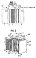
- FIG. 2 shows an exploded view of an externally manifolded fuel cell system 200 in accordance with the principles of the present invention.
- the fuel cell system 200 has a fuel cell stack 1 and a manifold 6 covering a face la of the stack 1.
- An electrical isolating assembly 201 is disposed between the fuel cell stack 1 and the manifold 6 for electrically isolating the manifold 6 from the stack.
- the assembly 201 has a similar construction as the electrical isolating assembly 101 of FIG. 1 and comprises a dielectric member 5, a wet gasket 2, which abuts the stack face 1a, followed by a ceramic block 3 and a dry gasket 4 disposed in an abutting relationship with one another.
- the members 2-5 are all formed to have picture-frame configurations.
- the dielectric member 5 has high dielectric resistivity, i.e. greater than 10 8 ohm-cm at 600°C.
- Mica sheet materials such as 503P phlogopite mica manufactured by Cogebi, Inc. may be used to form the dielectric member 5.
- the fuel cell stack 1 has a large electrical potential gradient along its length. As shown, the negative potential end 1b of the stack 1 having the negative terminal 1b1 is at a negative-most electrical potential, while the positive potential end 1c of the stack having the positive terminal 1c1 is at a positive-most potential.
- the manifold 6 is at a constant electrical potential which is between the positive-most and the negative-most electrical potentials of the stack 1. In particular, the manifold 6 is at a lower electrical potential than the electrical potential at the positive potential end 1c of the stack. As discussed above, this causes electrolyte to flow from the end 1c of the stack to the manifold through the electrical isolation assembly 101.
- the fuel cell system 200 is provided with a unit 7 for adjusting the electrical potential of the manifold 6 so as to impede electrolyte flow from the stack to the manifold.
- the unit 7 adjusts the electrical potential of the manifold 6 so that it approaches the electrical potential of the positive end 1c of the stack.
- this adjustment is such that the electrical potential at the manifold 6 becomes equal to or greater than the electrical potential at the stack end 1c.
- the unit 7 is in the form of a power supply 7a connected between the stack end 1c and the manifold 6.
- the power supply can be a battery having its positive terminal 7a1 connected to the manifold 6 and its negative terminal 7a2 connected to the positive end 1c of the stack 1. Batteries, such as 12 volt car battery, are suitable for use as the power supply 7a.
- the power supply 7a applies a positive electrical potential to the manifold 6 to increase the manifolds' electrical potential so that it approaches that at the positive end 1c of the stack.
- the battery potential is such that it is equal to or exceeds the potential at the stack end 1c.
- the electrical potential gradient between the stack 1 and the manifold 6 is at least decreased and in the preferred form of the battery 7, is zeroed or is reversed.
- the carbonate ions at the stack face 1a are less attracted to the manifold 6 and, therefore, the driving of the electrolyte across the isolating assembly 201 is at least reduced, if not stopped or reversed.
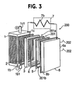
- FIG. 3 shows an alternative embodiment of the fuel cell system 200 of FIG. 2 in accord with the present invention.
- the unit 7 is in the form of an electrical conductor 7b which connects the positive end 1c of the fuel cell stack 1 to the manifold 6.
- the conductor 7b typically might be an electrical wire sized according to the National Electrical Code.
- a typical wire might be a 1/16 inch SS316 welding rod.
- the electrical conductor might also contain a resistor and a fuse sized according to the National Electric Code based on a power rating of the fuel cell.
- the presence of the electrical conductor 7b acts similarly to the battery in FIG. 2 , causing the potential at the manifold to become closer to that at the positive potential end 1c of the stack. This, in turn, acts to reduce or retard electrolyte flow from the stack through the electrical isolating assembly 201, thereby tending to preserve its electrical isolating characteristics. Accordingly, electrical isolation can be better maintained between the manifold 6 and the stack 1 over the operating life of the stack.
- the system 200 usually will have like manifolds 6 and associated isolating assemblies 201 adjacent one or more of the other faces of the stack.
- these manifolds will be connected electrically so as to be at the same potential.
- a common stack manifold clamping system or a wire or wires 202 such as a 1/16 inch SS316 welding rod, may be used so as to provide the electrical connection.
- the unit 7 between one of the manifolds and its associated stack face will be sufficient to provide all manifolds with a potential closer to that of the positive end 1c of the stack.
- a unit 7 can be provided between each face of the stack at the positive potential end of the stack and the facing manifold.
- the fuel cell system 200 shown in FIGS. 2 and 3 may be further modified to provide a barrier to prevent debris from compromising the electrical or dielectric isolation between the manifold 6 and the stack 1.
- debris comprising conductive materials is typically formed in the system 200 due to the presence of corrosive materials at high temperatures. This debris accumulates on the upper outer surface 201a of the electrical isolation assembly 201 and the upper surface at the upper end 6a of the manifold 6 and also on the upper inner surface 201b of the assembly 201 and the upper surface at the lower end 6b of the manifold 6.
- Accumulation of such conductive debris may compromise electrical isolation between the stack 1 and the manifold 6 if the debris forms a bridge between the manifold 6 and the electrical isolation assembly components which are adjacent the stack, i.e., the ceramic block 3 and/or the wet gasket 2.
- FIG. 4A shows an exploded side view of a modified arrangement of the fuel cell' system 200 of FIGS. 2 and 3 adapted to inhibit the bridging of this debris.
- the electrical isolating assembly 201 shown in FIGS. 2 and 3 has been modified to provide a dielectric member 5 whose upper end 5a has an outer surface 5a1 which extends beyond the upper outer surfaces 3a1, 4a1 and 6a1 of the upper outer ends 3a, 4a and 6a of the ceramic block 3, dry gasket 4 and manifold 6, respectively.
- the upper inner surface 5b1 of the lower end 5b of the dielectric member 5 extends above the upper inner surfaces 3b1, 4b1, 6b1 of the lower ends 3b, 4b and 6b of the gasket 3, ceramic block 4 and manifold 6.
- dielectric member 5 forms a physical barrier separating the surfaces 3a1 and 4a1 from the surface 6a1 and the surfaces 3b1 and 4b1 from the surface 6b1.
- the debris on the ceramic block 3 and dry gasket 4 is thus prevented from bridging with the debris on the manifold 6.
- the electrical coupling or connection of these elements and, thus, the manifold and stack by the debris 9 is thus avoided.
- FIG. 4B shows a front view of the dielectric member 5 of FIG. 4A viewed from the face of the dielectric member 5 abutting the dry gasket 4.
- the manifold 6, shown in dashed lines in FIG. 4B abuts the opposed face of the dielectric member 5.
- the upper surface 5a1 of the upper outer end 5a of the dielectric member 5 extends beyond the upper surface 6a 1 of the upper outer end 6a of the manifold 6 so as to form a barrier, as discussed above. As also discussed above, this barrier prevents debris on the surfaces 3a1 and 4a1 from bridging with the debris on the surface 6a1.
- the upper surface 5b1 of the lower end 5b of the dielectric members 5 extends beyond upper surface 6b1 of tbe lower end 6b of the manifold 6 so as bo form another barrier.
- This barrier similarly prevents debris on the surfaces 3b1, 4b1 from bridging with the debris on the surface 6b1.
Landscapes
- Life Sciences & Earth Sciences (AREA)
- Engineering & Computer Science (AREA)
- Manufacturing & Machinery (AREA)
- Sustainable Development (AREA)
- Sustainable Energy (AREA)
- Chemical & Material Sciences (AREA)
- Chemical Kinetics & Catalysis (AREA)
- Electrochemistry (AREA)
- General Chemical & Material Sciences (AREA)
- Fuel Cell (AREA)
Applications Claiming Priority (2)
| Application Number | Priority Date | Filing Date | Title |
|---|---|---|---|
| US11/020,593 US7276304B2 (en) | 2004-12-23 | 2004-12-23 | Fuel cell system including a unit for electrical isolation of a fuel cell stack from a manifold assembly and method therefor |
| PCT/US2005/047002 WO2006071841A2 (en) | 2004-12-23 | 2005-12-22 | Fuel cell system including a unit for electrical isolation of a fuel cell stack from a manifold assembly and method therefor |
Publications (3)
| Publication Number | Publication Date |
|---|---|
| EP1839355A2 EP1839355A2 (en) | 2007-10-03 |
| EP1839355A4 EP1839355A4 (en) | 2009-08-05 |
| EP1839355B1 true EP1839355B1 (en) | 2011-11-09 |
Family
ID=36611997
Family Applications (1)
| Application Number | Title | Priority Date | Filing Date |
|---|---|---|---|
| EP05855543A Expired - Lifetime EP1839355B1 (en) | 2004-12-23 | 2005-12-22 | Fuel cell system including a unit for electrical isolation of a fuel cell stack from a manifold assembly and method therefor |
Country Status (6)
| Country | Link |
|---|---|
| US (1) | US7276304B2 (enExample) |
| EP (1) | EP1839355B1 (enExample) |
| JP (1) | JP2008525970A (enExample) |
| KR (1) | KR101310483B1 (enExample) |
| CN (1) | CN101088186A (enExample) |
| WO (1) | WO2006071841A2 (enExample) |
Families Citing this family (5)
| Publication number | Priority date | Publication date | Assignee | Title |
|---|---|---|---|---|
| US8088697B2 (en) * | 2008-09-18 | 2012-01-03 | Fuelcell Energy, Inc. | Fibrous ceramic material and method for making the same |
| US9515346B2 (en) | 2009-06-19 | 2016-12-06 | Audi Ag | Power plant fuse arrangement |
| US9005837B2 (en) | 2009-10-29 | 2015-04-14 | Fuelcell Energy, Inc. | Gasket for fuel cell system manifold seal |
| US8541144B2 (en) | 2009-10-29 | 2013-09-24 | Fuelcell Energy, Inc. | Fuel cell system manifold seal |
| US10283804B2 (en) | 2016-10-21 | 2019-05-07 | General Electric Company | Flange assembly for use with a solid oxide fuel cell system |
Family Cites Families (9)
| Publication number | Priority date | Publication date | Assignee | Title |
|---|---|---|---|---|
| US4467018A (en) * | 1981-07-31 | 1984-08-21 | Electric Power Research Institute | Manifold dielectric barrier for a fuel cell electrical power generation system |
| US4414294A (en) * | 1982-09-27 | 1983-11-08 | The United States Of America As Represented By The U.S. Department Of Energy | Electrically insulating and sealing frame |
| JPS59214169A (ja) * | 1983-05-20 | 1984-12-04 | Hitachi Ltd | 燃料電池 |
| JPH06275303A (ja) * | 1993-03-17 | 1994-09-30 | Sanyo Electric Co Ltd | 外部マニホールド方式溶融炭酸塩型燃料電池 |
| US5607786A (en) * | 1995-05-05 | 1997-03-04 | International Fuel Cells Corporation | Fuel cell transport frame |
| US6410161B1 (en) * | 1999-04-15 | 2002-06-25 | Fuelcell Energy, Inc. | Metal-ceramic joint assembly |
| US6413665B1 (en) * | 2000-08-31 | 2002-07-02 | Fuelcell Energy, Inc. | Fuel cell stack compression system |
| US20020164519A1 (en) * | 2000-12-13 | 2002-11-07 | Jian Li | Electrolyte creepage barrier for liquid electrolyte fuel cells |
| US20050058872A1 (en) | 2003-09-12 | 2005-03-17 | Blanchet Scott C. | Connection assembly for promoting electrical isolation |
-
2004
- 2004-12-23 US US11/020,593 patent/US7276304B2/en not_active Expired - Lifetime
-
2005
- 2005-12-22 KR KR1020077016881A patent/KR101310483B1/ko not_active Expired - Lifetime
- 2005-12-22 EP EP05855543A patent/EP1839355B1/en not_active Expired - Lifetime
- 2005-12-22 JP JP2007548574A patent/JP2008525970A/ja active Pending
- 2005-12-22 CN CNA2005800445381A patent/CN101088186A/zh active Pending
- 2005-12-22 WO PCT/US2005/047002 patent/WO2006071841A2/en not_active Ceased
Also Published As
| Publication number | Publication date |
|---|---|
| JP2008525970A (ja) | 2008-07-17 |
| CN101088186A (zh) | 2007-12-12 |
| KR101310483B1 (ko) | 2013-09-24 |
| US7276304B2 (en) | 2007-10-02 |
| US20060141306A1 (en) | 2006-06-29 |
| WO2006071841B1 (en) | 2007-05-03 |
| WO2006071841A3 (en) | 2007-03-01 |
| EP1839355A4 (en) | 2009-08-05 |
| WO2006071841A2 (en) | 2006-07-06 |
| KR20070091032A (ko) | 2007-09-06 |
| EP1839355A2 (en) | 2007-10-03 |
Similar Documents
| Publication | Publication Date | Title |
|---|---|---|
| US4855193A (en) | Bipolar fuel cell | |
| US7150931B1 (en) | Fuel cell gas separator | |
| US10923728B1 (en) | Current collector structures for rechargeable battery | |
| US5643696A (en) | Battery plates with lightweight cores | |
| KR20160137573A (ko) | 연료 전지 스택 배열 | |
| EP0472152B1 (en) | Gasket for a battery of molten carbonate fuel cells | |
| EP1298755B1 (en) | Fuel cell stack having foil interconnects and laminated spacers | |
| JP4592940B2 (ja) | 固体高分子型燃料電池スタック | |
| GB2083278A (en) | Connector for electrochemical storage cells | |
| EP1839355B1 (en) | Fuel cell system including a unit for electrical isolation of a fuel cell stack from a manifold assembly and method therefor | |
| US7261965B2 (en) | Fuel cell module | |
| JP2003086229A (ja) | 燃料電池のスタック構造 | |
| US11721839B2 (en) | Electrode assembly with improved connection between electrode tabs | |
| EP1756896B1 (en) | Fuell cell stack | |
| US20050202298A1 (en) | Fuel cell | |
| JP4432291B2 (ja) | 燃料電池 | |
| KR20230012023A (ko) | 고온 반응부의 단열 구조 | |
| US20050130015A1 (en) | Molten carbonate fuel cell and method for production thereof | |
| KR20250110286A (ko) | 바이폴라 고체 상태 배터리 셀 | |
| RU2737037C1 (ru) | Электрохимическое устройство и батарея | |
| CN105637676B (zh) | 包括用于过充电保护的导电部分的电化学能量存储装置 | |
| KR102112679B1 (ko) | 부식 완화를 위한 외부 전극을 포함하는 연료 전지 스택 | |
| JP2024042644A (ja) | 電気化学装置 | |
| KR20240049152A (ko) | 축전 장치 | |
| KR20240099059A (ko) | 온도 제어가 최적화된 배터리 |
Legal Events
| Date | Code | Title | Description |
|---|---|---|---|
| PUAI | Public reference made under article 153(3) epc to a published international application that has entered the european phase |
Free format text: ORIGINAL CODE: 0009012 |
|
| 17P | Request for examination filed |
Effective date: 20070720 |
|
| AK | Designated contracting states |
Kind code of ref document: A2 Designated state(s): AT BE BG CH CY CZ DE DK EE ES FI FR GB GR HU IE IS IT LI LT LU LV MC NL PL PT RO SE SI SK TR |
|
| AX | Request for extension of the european patent |
Extension state: AL BA HR MK YU |
|
| DAX | Request for extension of the european patent (deleted) | ||
| RBV | Designated contracting states (corrected) |
Designated state(s): DE IT |
|
| A4 | Supplementary search report drawn up and despatched |
Effective date: 20090706 |
|
| 17Q | First examination report despatched |
Effective date: 20091221 |
|
| REG | Reference to a national code |
Ref country code: DE Ref legal event code: R079 Ref document number: 602005031172 Country of ref document: DE Free format text: PREVIOUS MAIN CLASS: H01M0008000000 Ipc: H01M0008140000 |
|
| GRAP | Despatch of communication of intention to grant a patent |
Free format text: ORIGINAL CODE: EPIDOSNIGR1 |
|
| RIC1 | Information provided on ipc code assigned before grant |
Ipc: H01M 8/02 20060101ALN20110421BHEP Ipc: H01M 8/24 20060101ALI20110421BHEP Ipc: H01M 8/14 20060101AFI20110421BHEP |
|
| RIN1 | Information on inventor provided before grant (corrected) |
Inventor name: FAROOQUE, MOHAMMAD Inventor name: DAVIS, KEITH Inventor name: KELLEY, DANA, A. |
|
| GRAS | Grant fee paid |
Free format text: ORIGINAL CODE: EPIDOSNIGR3 |
|
| GRAA | (expected) grant |
Free format text: ORIGINAL CODE: 0009210 |
|
| AK | Designated contracting states |
Kind code of ref document: B1 Designated state(s): DE IT |
|
| REG | Reference to a national code |
Ref country code: DE Ref legal event code: R096 Ref document number: 602005031172 Country of ref document: DE Effective date: 20120119 |
|
| PG25 | Lapsed in a contracting state [announced via postgrant information from national office to epo] |
Ref country code: IT Free format text: LAPSE BECAUSE OF FAILURE TO SUBMIT A TRANSLATION OF THE DESCRIPTION OR TO PAY THE FEE WITHIN THE PRESCRIBED TIME-LIMIT Effective date: 20111109 |
|
| PLBE | No opposition filed within time limit |
Free format text: ORIGINAL CODE: 0009261 |
|
| STAA | Information on the status of an ep patent application or granted ep patent |
Free format text: STATUS: NO OPPOSITION FILED WITHIN TIME LIMIT |
|
| 26N | No opposition filed |
Effective date: 20120810 |
|
| REG | Reference to a national code |
Ref country code: DE Ref legal event code: R097 Ref document number: 602005031172 Country of ref document: DE Effective date: 20120810 |
|
| P01 | Opt-out of the competence of the unified patent court (upc) registered |
Effective date: 20230508 |
|
| PGFP | Annual fee paid to national office [announced via postgrant information from national office to epo] |
Ref country code: DE Payment date: 20241029 Year of fee payment: 20 |