EP1839020B1 - Statische, zweidimensionale öffnungskodierung für multimodale multiplex-spektroskopie - Google Patents
Statische, zweidimensionale öffnungskodierung für multimodale multiplex-spektroskopie Download PDFInfo
- Publication number
- EP1839020B1 EP1839020B1 EP06718717.9A EP06718717A EP1839020B1 EP 1839020 B1 EP1839020 B1 EP 1839020B1 EP 06718717 A EP06718717 A EP 06718717A EP 1839020 B1 EP1839020 B1 EP 1839020B1
- Authority
- EP
- European Patent Office
- Prior art keywords
- mask
- spectrometer
- source
- matrix
- multimode multiplex
- Prior art date
- Legal status (The legal status is an assumption and is not a legal conclusion. Google has not performed a legal analysis and makes no representation as to the accuracy of the status listed.)
- Active
Links
- 230000003068 static effect Effects 0.000 title claims description 40
- 238000004611 spectroscopical analysis Methods 0.000 title description 20
- 230000003595 spectral effect Effects 0.000 claims description 70
- 239000011159 matrix material Substances 0.000 claims description 48
- 230000006870 function Effects 0.000 claims description 43
- 238000001228 spectrum Methods 0.000 claims description 38
- 230000003287 optical effect Effects 0.000 claims description 36
- 230000005855 radiation Effects 0.000 claims description 23
- 238000000034 method Methods 0.000 claims description 16
- 230000001419 dependent effect Effects 0.000 claims description 12
- 238000012545 processing Methods 0.000 claims description 12
- 238000005286 illumination Methods 0.000 claims description 11
- 230000009466 transformation Effects 0.000 claims description 7
- 239000006185 dispersion Substances 0.000 claims description 6
- 238000012546 transfer Methods 0.000 claims description 6
- 239000000835 fiber Substances 0.000 claims description 4
- 239000005337 ground glass Substances 0.000 claims description 4
- 230000000295 complement effect Effects 0.000 claims 1
- 238000003384 imaging method Methods 0.000 description 34
- 238000010586 diagram Methods 0.000 description 21
- 238000012937 correction Methods 0.000 description 13
- 230000005540 biological transmission Effects 0.000 description 12
- 238000000265 homogenisation Methods 0.000 description 12
- 238000013461 design Methods 0.000 description 11
- 230000008901 benefit Effects 0.000 description 9
- 239000013598 vector Substances 0.000 description 9
- 238000004891 communication Methods 0.000 description 7
- 238000004458 analytical method Methods 0.000 description 6
- 238000005259 measurement Methods 0.000 description 5
- 238000013459 approach Methods 0.000 description 4
- 238000003491 array Methods 0.000 description 4
- 230000000694 effects Effects 0.000 description 4
- 230000010354 integration Effects 0.000 description 4
- 238000006243 chemical reaction Methods 0.000 description 3
- 238000006073 displacement reaction Methods 0.000 description 3
- 230000009467 reduction Effects 0.000 description 3
- 230000004044 response Effects 0.000 description 3
- 229910052724 xenon Inorganic materials 0.000 description 3
- FHNFHKCVQCLJFQ-UHFFFAOYSA-N xenon atom Chemical compound [Xe] FHNFHKCVQCLJFQ-UHFFFAOYSA-N 0.000 description 3
- 238000012512 characterization method Methods 0.000 description 2
- 238000010276 construction Methods 0.000 description 2
- 238000004519 manufacturing process Methods 0.000 description 2
- 239000007787 solid Substances 0.000 description 2
- 238000012935 Averaging Methods 0.000 description 1
- VYZAMTAEIAYCRO-UHFFFAOYSA-N Chromium Chemical compound [Cr] VYZAMTAEIAYCRO-UHFFFAOYSA-N 0.000 description 1
- 238000001069 Raman spectroscopy Methods 0.000 description 1
- 238000004847 absorption spectroscopy Methods 0.000 description 1
- 125000004122 cyclic group Chemical group 0.000 description 1
- 230000003247 decreasing effect Effects 0.000 description 1
- 238000011161 development Methods 0.000 description 1
- 238000005516 engineering process Methods 0.000 description 1
- 238000002474 experimental method Methods 0.000 description 1
- 238000001914 filtration Methods 0.000 description 1
- 238000001506 fluorescence spectroscopy Methods 0.000 description 1
- 230000006872 improvement Effects 0.000 description 1
- 238000002329 infrared spectrum Methods 0.000 description 1
- 230000000670 limiting effect Effects 0.000 description 1
- 239000004973 liquid crystal related substance Substances 0.000 description 1
- 238000013178 mathematical model Methods 0.000 description 1
- 238000012986 modification Methods 0.000 description 1
- 230000004048 modification Effects 0.000 description 1
- 230000008569 process Effects 0.000 description 1
- 230000000135 prohibitive effect Effects 0.000 description 1
- 239000010453 quartz Substances 0.000 description 1
- 229910052704 radon Inorganic materials 0.000 description 1
- SYUHGPGVQRZVTB-UHFFFAOYSA-N radon atom Chemical compound [Rn] SYUHGPGVQRZVTB-UHFFFAOYSA-N 0.000 description 1
- 230000002829 reductive effect Effects 0.000 description 1
- VYPSYNLAJGMNEJ-UHFFFAOYSA-N silicon dioxide Inorganic materials O=[Si]=O VYPSYNLAJGMNEJ-UHFFFAOYSA-N 0.000 description 1
- 238000010183 spectrum analysis Methods 0.000 description 1
- 239000000758 substrate Substances 0.000 description 1
- 238000011282 treatment Methods 0.000 description 1
Images


Classifications
-
- G—PHYSICS
- G01—MEASURING; TESTING
- G01J—MEASUREMENT OF INTENSITY, VELOCITY, SPECTRAL CONTENT, POLARISATION, PHASE OR PULSE CHARACTERISTICS OF INFRARED, VISIBLE OR ULTRAVIOLET LIGHT; COLORIMETRY; RADIATION PYROMETRY
- G01J3/00—Spectrometry; Spectrophotometry; Monochromators; Measuring colours
- G01J3/28—Investigating the spectrum
- G01J3/2846—Investigating the spectrum using modulation grid; Grid spectrometers
-
- G—PHYSICS
- G01—MEASURING; TESTING
- G01J—MEASUREMENT OF INTENSITY, VELOCITY, SPECTRAL CONTENT, POLARISATION, PHASE OR PULSE CHARACTERISTICS OF INFRARED, VISIBLE OR ULTRAVIOLET LIGHT; COLORIMETRY; RADIATION PYROMETRY
- G01J3/00—Spectrometry; Spectrophotometry; Monochromators; Measuring colours
- G01J3/02—Details
- G01J3/0205—Optical elements not provided otherwise, e.g. optical manifolds, diffusers, windows
- G01J3/0208—Optical elements not provided otherwise, e.g. optical manifolds, diffusers, windows using focussing or collimating elements, e.g. lenses or mirrors; performing aberration correction
-
- G—PHYSICS
- G01—MEASURING; TESTING
- G01J—MEASUREMENT OF INTENSITY, VELOCITY, SPECTRAL CONTENT, POLARISATION, PHASE OR PULSE CHARACTERISTICS OF INFRARED, VISIBLE OR ULTRAVIOLET LIGHT; COLORIMETRY; RADIATION PYROMETRY
- G01J3/00—Spectrometry; Spectrophotometry; Monochromators; Measuring colours
- G01J3/02—Details
- G01J3/0205—Optical elements not provided otherwise, e.g. optical manifolds, diffusers, windows
- G01J3/0218—Optical elements not provided otherwise, e.g. optical manifolds, diffusers, windows using optical fibers
-
- G—PHYSICS
- G01—MEASURING; TESTING
- G01J—MEASUREMENT OF INTENSITY, VELOCITY, SPECTRAL CONTENT, POLARISATION, PHASE OR PULSE CHARACTERISTICS OF INFRARED, VISIBLE OR ULTRAVIOLET LIGHT; COLORIMETRY; RADIATION PYROMETRY
- G01J3/00—Spectrometry; Spectrophotometry; Monochromators; Measuring colours
- G01J3/02—Details
- G01J3/0205—Optical elements not provided otherwise, e.g. optical manifolds, diffusers, windows
- G01J3/0229—Optical elements not provided otherwise, e.g. optical manifolds, diffusers, windows using masks, aperture plates, spatial light modulators or spatial filters, e.g. reflective filters
Definitions
- the throughput of an optical instrument can be approximated as the product of the area of the input aperture and the solid angle from which the instrument will accept light.
- the acceptance solid angle is determined by the internal optics of an instrument.
- the only way to increase the etendue of the system is to increase the size of the input aperture.
- such an approach reduces the resolution of the spectrometer as it increases the throughput.
- a design that solves the first problem is said to have a Jacquinot (or large-area or throughput) advantage.
- a design that solves the second problem is said to have a Fellgett (or multiplex) advantage.
- a coded aperture or mask is used to convert intensity information into frequency or spectral information.
- the basic elements of a coded aperture imaging spectrometer are described in Mende and Claflin, U.S. Pat. No. 5,627,639 (the '639 patent), for example.
- Light from multiple locations on a target is incident on a mask.
- the mask contains rows and columns of both transmissive and opaque elements.
- the transmissive and opaque elements are located on the mask according to a transfer function used to convert intensity information of the incident light to spectral information.
- the transmissive elements transmit the incident light, and the opaque elements block the incident light.
- a grating is used to disperse the transmitted light from the transmissive elements in a linear spatial relationship, according to the wavelength of the transmitted light.
- the dispersed light is incident on a detector array.
- the detector array contains rows and columns of detector elements.
- the detector array elements are designed to receive a different range of wavelengths from each transmissive element of the mask and provide a signal indicative the intensity of the light received.
- the mask is translated in one direction relative to the target over time.
- a data matrix is generated.
- the data matrix contains light intensity data from each row of the detector array as light incident from the same target elements passes through a corresponding row of the mask.
- the intensities recorded by the rows and columns of detector elements are collected over time and assembled in a data matrix for each set of target elements.
- a frequency spectrum is obtained for each set of target elements by converting the data matrix according to the transfer function.
- a pattern matrix is predetermined from the mathematical representation of the mask elements. Transmissive elements of the mask are represented as a '1' in the pattern mask, and opaque elements of the mask are represented as a '0' in the pattern mask.
- a frequency matrix representing the frequency spectrum is obtained by multiplying the data matrix by the inverse pattern matrix and a factor that is a function of the number of transmissive elements and number of total mask elements.
- Coded aperture spectroscopy was proposed in Golay, M. J. E. (1951), "Static multislit spectrometry and its application to the panoramic display of infrared spectra," Journal of the Optical Society of America 41(7): 468-472 .
- Two-dimensional coded apertures for spectroscopy were developed in the late 1950's and early 1960's as described, for example, in Girard, A. (1960), "Nouveaux gebers de spectroscopie a grande luminosite,” Optica Acta 7(1): 81 - 97 .
- coded aperture spectroscopy instruments were limited to single optical detector elements or small arrays of discrete detectors. Reliance on single detectors required mechanical, electro-optical, liquid crystal, or other forms of modulation to read spectral data. These early coded aperture instruments implemented spectral processing by using both an entrance and an exit coded aperture and a single detector element or a detector element pair.
- High quality two-dimensional electronic detector arrays were in use by the 1990's, as described in the '639 patent, for example.
- coded aperture instruments combining entrance and exit coded apertures for two-dimensional codes are still in use today, as described, for example in Shlishevsky, V. B. (2002), "Methods of high-aperture grid spectroscopy," Journal Of Optical Technology 69(5): 342-353 .
- Aperture coding is not the only approach to solving these spectrometer design problems.
- Interferometric spectrometers such as Fourier transform (FT) spectrometers, can also exhibit the Jacquinot and Fellgett advantages.
- the FT spectrometer in fact exhibits both.
- the majority of FT spectrometers contain mechanical scanning elements.
- a class of aperture coded spectrometer is optimized for the spectral characterization of diffuse sources.
- the spectrometer achieves high throughput and high spatial resolution by replacing the slit of conventional dispersive spectrometers with a spatial filter or mask.
- a number of masks can be used including Harmonic masks, Legendre masks, and Hadamard masks.
- the present invention is a static multimode multiplex spectrometer (MMS) as defined in claim 1.
- MMS includes a two-dimensional orthogonal column code mask, wherein source radiation is incident on the mask, wherein the transmissive and opaque elements of the mask are arranged according to a transfer function represented mathematically as a coding matrix, and wherein each column of the coding matrix is orthogonal under an inner product transformation.
- the MMS further includes a dispersive element aligned with the code mask, wherein source radiation transmitted through the mask is incident on the dispersive element such that the dispersive element induces a wavelength dependent spatial shift of the image of the mask.
- Embodiments of systems and methods relate to a two-dimensional orthogonal column code multimodal spectrometer and spectral imager are described in this detailed description of the invention, which includes the accompanying Appendix 1 of the '522 application and Appendix 1 of the '173 application.
- Appendix 1 of the '522 application and Appendix 1 of the '173 application.
- numerous specific details are set forth to provide a thorough understanding of embodiments of the present invention.
- One skilled in the art will appreciate, however, that embodiments of the present invention may be practiced without these specific details.
- structures and devices are shown in block diagram form.
- one skilled in the art can readily appreciate that the specific sequences in which methods are presented and performed are illustrative and it is contemplated that the sequences can be varied and still remain within the spirit and scope of embodiments of the present invention.
- a primary goal of a static multimode multiplex spectrometer is to estimate the mean spectral density S ( ⁇ ) of a diffuse (multimodal) source.
- Static refers to the lack of mechanical, electro-optical or other active modulation in forming the source estimate.
- a preferred static MMS estimates S ( ⁇ ) in a single time step of parallel measurements.
- a preferred MMS system measures spectral projections of the field drawn from diverse modes or points and combines these projections to produce an estimate of the mean spectral density.
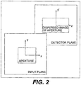
- FIG. 1 is a schematic diagram of an exemplary MMS system 100, in accordance with an embodiment of the present invention.
- System 100 is a grating spectrometer with a two-dimensional coded aperture mask 110 taking the place of the entrance slit of a conventional system. Unlike many previous coded aperture spectrometers, system 100 does not use an output slit. The output aperture is fully occupied by a two-dimensional optical detector array 120.
- System 100 images aperture coding mask 110 onto optical detector array 120, through a dispersive element 130.
- Aperture coding mask 110 preferably contains aperture codes and weighting on the aperture codes such that each column of the pattern or coding matrix is orthogonal under an inner product transformation.
- Optical detector array 120 is a two-dimensional charge coupled device (CCD), for example.
- Dispersive element 130 can include but is not limited to a grating, a holographic grating, or a prism. Dispersive element 130 can include a combination of dispersive elements. Dispersive element 130 induces a wavelength dependent spatial shift of the image of aperture coding mask 110 on detector array 120.
- System 100 preferably includes a relay optical system 140.
- Relay optical system 140 is used to convert a non-uniform spectral density of source radiation 150 to a substantially uniform spectral density in at least one direction.
- System 100 also preferably includes an imaging lens system 160 and an imaging lens system 170. The combined imaging system 160 and 170 is designed to form an image of the aperture mask 110 on the focal plane 120 through the grating 130 such that the image position shifts linearly as a function of illumination wavelength.
- H(x, y) is the kernel describing propagation through the spectrometer
- T(x, y) is a transmission function describing the input aperture
- S(xy, ⁇ ) is the input spectral density at position (x, y).
- unprimed variables denote quantities defined in the input plane
- primed variables denote quantities in the detector plane.
- Eqn. (14) reveals that the intensity profile in the detector plane is a direct estimate of the spectral density at the slit location.
- the drawback to such an approach is that the throughput of the system is severely curtailed. More complicated aperture patterns, however, can increase the photon collection efficiency of the system.
- a goal of the MMS is to develop an aperture code that permits estimation of the mean spectrum across an extended aperture.
- the mean spectrum across an extended aperture is defined as: S mean ⁇ ⁇ ⁇ dxdyS x y ⁇ .
- S ( x, y, ⁇ ) is constant, or slowly varying in y .
- S ( x , y , ⁇ ) can be written as: S x y ⁇ ⁇ I y S x ⁇
- Eqn. (20) can be interpreted as a two-dimensional function containing estimates of the input spectrum at different input locations. A slice through this function at a constant value of x" corresponds to the input spectrum at a particular value of x. In other words, at this point, a 1D imaging spectrometer. has been created. Conversion of E(x', x") into an estimate of S mean ( ⁇ ) is described below.
- the codes have been chosen such that the transmission has physically-realizable values in the interval [0,1].
- the exemplary pattern illustrated in Fig. 3 is continuous vertically, but discrete horizontally.
- the functions form a self-adjoint set of codes: T X , T ⁇ x ⁇ ⁇ P m y Y , m ⁇ Z + .
- the codes have been chosen such that the transmission has physically-realizable values in the interval [0,1].
- the exemplary pattern illustrated in Fig. 4 is continuous vertically, but discrete horizontally.
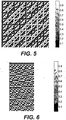
- FIG. 5 An aperture based on an S-matrix code is shown in Fig. 5 .
- the codes have been chosen such that the transmission has physically-realizable values in the interval [0,1].
- the exemplary pattern illustrated in Fig. 5 is discrete both horizontally and vertically.
- the aperture must be designed so that when imaged onto the detector, the features involve integral numbers of pixels in the y' direction. This places performance requirements on the manufacturing accuracy of the aperture and the magnification of the relay optics in the spectrometer.
- Arbitrarily-patterned, continuous-tone masks with transmissions ranging from 0-100% are indeed possible. However, given the complexity of most orthogonal column code patterns, the cost to manufacture transmission masks to the required precision is prohibitive.
- One alternative is to convert the designed continuous-tone mask into a half-toned version. A small region of the continuous-tone pattern is subdivided into an array of even smaller subregions. Each of these subregions is assigned a transmission of either 0 or 100%, such that the net transmission in the region matches the grayscale value of the continuous-tone pattern. Provided that the conversion happens on a spatial scale that is smaller than the pixelization of the detector plane, no significant difference should be detectable.
- the internal optics of the spectrometer can have a significant effect on the performance of the system.
- the optical properties of a static MMS deviate from a traditional instrument in a critical manner. Because the MMS encodes spectral information across the detector plane in a highly non-local way, optical errors anywhere have a non-local effect on the reconstruction, introducing noise and errors at regions throughout the spectral range.
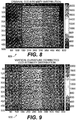
- Figure 9 is an exemplary CCD image 900 showing corrected spectral line curvature as a function of vertical field position, in accordance with an embodiment of the present invention.
- a digital correction technique is used that involves averaging the multiple spectral estimates. After the inversion of the formatted CCD data, spectral estimates at the different slit positions are determined.
- a reconstructed data set from a calibration source such as a pen lamp is also used.
- Vectors are then formed of the pixel positions of the strongest peaks in the spectra for each spectral estimate.
- Vectors are then formed of the required pixel positions in order to keep the spacing of the peaks the same in each estimate, since the source spectra line positions are fixed.
- a polynomial fit is performed to relate the column of the CCD and its deviation from these required pixel positions.
- the reconstructed spectra are then resampled using this polynomial fit onto a corrected axis.
- the spectra are aligned and summed in order to form a spectral estimate.
- the spectral source was a xenon discharge lamp operated in conjunction with an integrating sphere.
- the light from the integrating sphere was allowed to fall directly on the mask aperture no relay optics of any kind were used.
- the CCD integration time was 160 ms.
- the particular spectrometer has a spectral range of ⁇ 775 - 900 nm.
- the spectral resolution depends on the mask used. For the majority of the masks, the resolution is ⁇ ⁇ 0.65 nm.
- the masks consisted of chrome deposited on a quartz substrate. The smallest mask feature was 36 gm, corresponding to 4 pixels on the CCD.
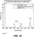
- Fig. 11 compares the spectrum reconstructed from an order-40, row-doubled Hadamard mask and from a slit with a width (36 ⁇ m) equal to the feature size of the mask. As can be seen from Fig. 11 , coded aperture collects significantly more light, without sacrificing spectral resolution.
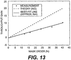
- Fig. 13 illustrates that the observed scaling is approximately N/4, rather than the expected N / 2 .
- MTF modulation transfer function
- Figure 15 is a schematic diagram showing an exemplary system 1500 for converting spatially non-uniform source of interest to a spatially uniform source of interest using a Fourier-transform lens 1510, in accordance with an embodiment of the present invention. If the source radiation is spatially incoherent in an input plane 1520, placing Fourier-transform lens 1510 between input plane 1520 and a mask plane 1530 produces a uniform illumination. Fourier-transform lens 1510 is situated one focal length from source input plane 1520 and one focal length from coding mask plane 1530.
- Figure 16 is a schematic diagram showing an exemplary system 1600 for converting a spatially non-uniform source of interest to a spatially uniform source of interest using a ground-glass diffuser 1610, in accordance with an embodiment of the present invention. If the incoherence of a source cannot be guaranteed, placing a ground glass diffuser 1610 between input plane 1620 and mask plane 1630 produces a uniform illumination.
- Figure 17 is a schematic diagram showing an exemplary system 1700 for converting a spatially non-uniform source of interest to a spatially uniform source of interest using a multimode fiber bundle 1710, in accordance with an embodiment of the present invention. Similarly, if the incoherence of a source cannot be guaranteed, placing multimode fiber bundle 1710 between input plane 1620 and mask plane 1630 produces a uniform illumination.
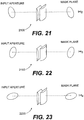
- Figures 19-23 illustrate image rotation in the input aperture of system 1800. Such rotation is achieved by a prism combination or by rotating the imaging spectrometer.
- x' and y' are transverse coordinates in a canonical coordinate system and x and y are rotated transverse coordinates.
- a computer-readable medium can be a device that stores digital information.
- a computer-readable medium includes a read-only memory (e.g., a Compact Disc-ROM ("CD-ROM”) as is known in the art for storing software.
- CD-ROM Compact Disc-ROM
- the computer-readable medium can be accessed by a processor suitable for executing instructions adapted to be executed.
- instructions configured to be executed and “instructions to be executed” are meant to encompass any instructions that are ready to be executed in their present form (e.g., machine code) by a processor, or require further manipulation (e.g., compilation, decryption, or provided with an access code, etc.) to be ready to be executed by a processor.
- Coupled encompasses a direct connection, an indirect connection, or a combination thereof.
- Two devices that are coupled can engage in direct communications, in indirect communications, or a combination thereof.
- two devices that are coupled need not be in continuous communication, but can be in communication typically, periodically, intermittently, sporadically, occasionally, and so on.
- communication is not limited to direct communication, but also includes indirect communication.
- Systems and methods in accordance with an embodiment of the present invention disclosed herein can advantageously maximize spectrometer throughput without sacrificing spectral resolution and maximize the signal-to-noise ratio of an estimated spectrum for a given system throughput and detector noise.
Landscapes
- Physics & Mathematics (AREA)
- Spectroscopy & Molecular Physics (AREA)
- General Physics & Mathematics (AREA)
- Spectrometry And Color Measurement (AREA)
- Analysing Materials By The Use Of Radiation (AREA)
Claims (25)
- Statisches Multimode-Multiplex-Spektrometer (100) zum Schätzen der spektralen Dichte einer diffusen Quelle in einem einzigen Zeitschritt, wobei das Spektrometer Folgendes umfasst:eine zweidimensionale orthogonale Spaltencodemaske (110), wobei Quellenstrahlung auf die Maske auftrifft, wobei die transmissiven und undurchsichtigen Elemente der Maske gemäß einer Transferfunktion angeordnet sind, die mathematisch als Codierungsmatrix dargestellt ist, und wobei jede Spalte der Codierungsmatrix unter einer inneren Produkttransformation unabhängig ist;ein dispersives Element (130), das mit der codierten Maske ausgerichtet ist, wobei eine Quellenstrahlung, die durch die Maske übertragen wird, auf das dispersive Element auftrifft, so dass das dispersive Element eine wellenlängenabhängige räumliche Verschiebung des Bildes der Maske induziert;eine zweidimensionale Detektoranordnung (120), die mit dem dispersiven Element ausgerichtet ist, wobei eine Quellenstrahlung aus dem dispersiven Element auf die Anordnung auftrifft, wobei die Anordnung Zeilen- und Spaltendetektorelemente umfasst und wobei die Detektorelemente das wellenlängenabhängige, räumlich verschobene Bild der Maske (110) in Lichtintensitätswerte in einem einzigen Zeitschritt umwandeln; undeine Verarbeitungseinheit; wobei die Verarbeitungseinheit die Werte in einer Datenmatrix speichert und eine Transformation der Datenmatrix unter Verwendung der Codierungsmatrix durchführt, um eine Spektrummatrix zu erzeugen, die eine mathematische Darstellung einer spektralen Dichte der Quellenstrahlung ist.
- Statisches Multimode-Multiplex-Spektrometer (100) nach Anspruch 1, wobei die Codierungsmatrix eine Hadamard-Matrix ist.
- Statisches Multimode-Multiplex-Spektrometer (100) nach Anspruch 1, wobei die Codierungsmatrix eine S-Matrix ist.
- Statisches Multimode-Multiplex-Spektrometer (100) nach Anspruch 1, wobei die Codierungsmatrix aus etwa orthogonalen Spalten besteht, die zufällige Sequenzen, pseudozufällige Sequenzen oder perfekte Sequenzen verwenden.
- Statisches Multimode-Multiplex-Spektrometer (100) nach Anspruch 1, wobei die Codierungsmatrix aus kontinuierlichen orthogonalen Funktionsfamilien gebildet ist, die harmonische Funktionen oder Wavelet-Funktionen umfassen.
- Statisches Multimode-Multiplex-Spektrometer (100) nach Anspruch 1, wobei die Codierungsmatrix aus kontinuierlichen orthogonalen Funktionsfamilien gebildet ist.
- Statisches Multimode-Multiplex-Spektrometer (100) nach Anspruch 1, wobei das dispersive Element (130) ein Gitter, ein holographisches Gitter und/oder ein Prisma ist.
- Statisches Multimode-Multiplex-Spektrometer (100) nach Anspruch 1, wobei die Anordnung (120) eine zweidimensionale ladungsgekoppelte Vorrichtung, eine aktive Pixel-Photodetektoranordnung, eine Mikrobolometeranordnung oder eine Photodiodenanordnung ist.
- Statisches Multimode-Multiplex-Spektrometer (100) nach Anspruch 1, wobei die Verarbeitungseinheit ein Computer, ein Mikroprozessor und/oder eine anwendungsspezifische Schaltung ist.
- Statisches Multimode-Multiplex-Spektrometer (100) nach Anspruch 1, wobei die Verarbeitungseinheit ein digitales Kompensationsverfahren verwendet, um die Spektrumlinienkrümmung und die nichtlineare Dispersion der Spektren auf die Detektoranordnung zu korrigieren.
- Statisches Multimode-Multiplex-Spektrometer (100) nach Anspruch 1, wobei das System verwendet werden kann, um ein eindimensionales räumliches Bild der Quellenstrahlungsspektraldichte anstelle der durchschnittlichen spektralen Dichte zu erhalten.
- Statisches Multimode-Multiplex-Spektrometer (100) nach Anspruch 1, wobei ein dreidimensionales Bild der Quellenstrahlungsspektraldichte durch Drehen einer Quelle, Drehen des statischen Multimode-Multiplex-Spektrometers und/oder Drehen einer Darstellung der Quelle in Bezug auf das statische Multimode-Multiplex-Spektrometer gebildet wird.
- Statisches Multimode-Multiplex-Spektrometer (100) nach Anspruch 1, das ferner Folgendes umfasst: ein optisches System (140), das zwischen der Quellenstrahlung und der Maske angeordnet ist und eine ungleichförmige spektrale Dichte der Quellenstrahlung in eine im Wesentlichen gleichförmige spektrale Dichte in mindestens einer Richtung umwandelt.
- Statisches Multimode-Multiplex-Spektrometer (100) nach Anspruch 13, wobei eine Fourier-Transformationslinse (1510) zwischen der Quelle und der Maske (110) angeordnet ist, um eine räumlich ungleichförmige Quelle in eine räumlich gleichförmige umzuwandeln.
- Statisches Multimode-Multiplex-Spektrometer (100) nach Anspruch 13, wobei ein Grundglasdiffusor (1610) zwischen der Quelle und der Maske (110) angeordnet ist, um die Maske gleichmäßig zu beleuchten.
- Statisches Multimode-Multiplex-Spektrometer (100) nach Anspruch 13, wobei ein Multimode-Faserbündel (1710), das zwischen der Quelle und der Maske (110) angeordnet ist, eine gleichmäßige Beleuchtung erzeugt.
- Statisches Multimode-Multiplex-Spektrometer nach Anspruch 1,
wobei die Maske (110) aus einer Reihe von lithographisch geätzten Blenden besteht, um eine Codierung zu implementieren, wie sie durch eine diskrete Matrix, insbesondere eine Hadamard- oder S-Matrix einer bestimmten Ordnung, beschrieben ist. - Statisches Multimode-Multiplex-Spektrometer (110) nach Anspruch 17, wobei die Maske mit -1 Werten einer Hadamard-Matrix durch einen zeilenverdoppelten Hadamard realisiert wird, so dass jede Zeile durch zwei zueinander komplementäre Zeilen ersetzt wird.
- Statisches Multimode-Multiplex-Spektrometer (110) nach Anspruch 17, wobei die codierte Maske durch Umwandlung der Maske mit kontinuierlichem Ton in eine halb getönte Version hergestellt wird, um Graustufenmuster zu implementieren, wie sie von einer Familie unabhängiger Spaltencodes definiert sind.
- Statisches Multimode-Multiplex-Spektrometer (110) nach Anspruch 17, wobei die Maske, deren transmissiven und undurchsichtigen Elemente durch elektrische, optische oder mechanische Mittel automatisch oder manuell rekonfiguriert werden können, eine Vielzahl von Transformationen und eine Reihe von Blendengrößen erzeugt, die dem Spektrometer ermöglichen, die Eigenschaften der Quellenstrahlung optimal anzupassen.
- Statisches Multimode-Multiplex-Spektrometer (110) nach Anspruch 19, wobei die digitalen Verfahren angewendet werden können, um nur ausgewählte Abschnitte der Blende zu rekonstruieren, wodurch dies ein System mit variabler Blende wird, um unterschiedliche Beleuchtungsmuster der Quelle auf die Maske zu ermöglichen.
- Statisches Multimode-Multiplex-Spektrometer (110) nach Anspruch 20, wobei die digitalen Verfahren angewendet werden können, um nur ausgewählte Abschnitte der Blende zu rekonstruieren, wodurch dies ein System mit variabler Blende wird, um unterschiedliche Beleuchtungsmuster der Quelle auf die Maske zu ermöglichen.
- Statisches Multimode-Multiplex-Spektrometer (100) zum Schätzen der spektralen Dichte einer diffusen Quelle in einem einzigen Zeitschritt, wobei das Spektrometer Folgendes umfasst:eine zweidimensionale unabhängige Spaltencodemaske (110), wobei Quellenstrahlung auf die Maske auftrifft, wobei die transmissiven und undurchsichtigen Elemente der Maske gemäß einer Transferfunktion angeordnet sind, die mathematisch als Codierungsmatrix dargestellt ist, und wobei jede Spalte der Codierungsmatrix unter einer inneren Produkttransformation unabhängig ist;ein dispersives Element (130), das mit der codierten Maske ausgerichtet ist, wobei eine Quellenstrahlung, die durch die Maske übertragen wird, auf das dispersive Element auftrifft, so dass das dispersive Element eine wellenlängenabhängige räumliche Verschiebung des Bildes der Maske induziert;eine zweidimensionale Detektoranordnung (120), die mit dem dispersiven Element ausgerichtet ist, wobei eine Quellenstrahlung aus dem dispersiven Element auf die Anordnung auftrifft, wobei die Anordnung Zeilen- und Spaltendetektorelemente umfasst und wobei die Detektorelemente das wellenlängenabhängige, räumlich verschobene Bild der Maske in Lichtintensitätswerte in einem einzigen Zeitschritt umwandeln; undeine Verarbeitungseinheit; wobei die Verarbeitungseinheit die Werte in einer Datenmatrix speichert und eine Transformation der Datenmatrix unter Verwendung der Codierungsmatrix durchführt, um eine Spektrummatrix zu erzeugen, die eine mathematische Darstellung einer spektralen Dichte der Quellenstrahlung ist.
- Statisches Multimode-Multiplex-Spektrometer (100) nach Anspruch 23, das ferner Folgendes umfasst:ein optisches System (140), das zwischen der Quellenstrahlung und der Maske (110) angeordnet ist und eine ungleichförmige spektrale Dichte der Quellenstrahlung in eine im Wesentlichen gleichförmige spektrale Dichte in mindestens einer Richtung umwandelt.
- Statisches Multimode-Multiplex-Spektrometer (100) nach Anspruch 1,
wobei die Maske (110) aus einer Reihe von lithographisch geätzten Blenden besteht, um eine Codierung zu implementieren, wie sie durch eine diskrete Matrix, insbesondere eine Hadamard- oder S-Matrix einer bestimmten Ordnung, beschrieben ist.
Applications Claiming Priority (3)
| Application Number | Priority Date | Filing Date | Title |
|---|---|---|---|
| US64452205P | 2005-01-19 | 2005-01-19 | |
| US70517305P | 2005-08-04 | 2005-08-04 | |
| PCT/US2006/001685 WO2006078687A2 (en) | 2005-01-19 | 2006-01-19 | Static two-dimensional aperture coding for multimodal multiplex spectroscopy |
Publications (3)
| Publication Number | Publication Date |
|---|---|
| EP1839020A2 EP1839020A2 (de) | 2007-10-03 |
| EP1839020A4 EP1839020A4 (de) | 2011-11-23 |
| EP1839020B1 true EP1839020B1 (de) | 2017-04-26 |
Family
ID=36692804
Family Applications (1)
| Application Number | Title | Priority Date | Filing Date |
|---|---|---|---|
| EP06718717.9A Active EP1839020B1 (de) | 2005-01-19 | 2006-01-19 | Statische, zweidimensionale öffnungskodierung für multimodale multiplex-spektroskopie |
Country Status (4)
| Country | Link |
|---|---|
| US (2) | US7301625B2 (de) |
| EP (1) | EP1839020B1 (de) |
| JP (1) | JP5220420B2 (de) |
| WO (1) | WO2006078687A2 (de) |
Families Citing this family (31)
| Publication number | Priority date | Publication date | Assignee | Title |
|---|---|---|---|---|
| EP1839020B1 (de) * | 2005-01-19 | 2017-04-26 | Optopo Inc. D/B/A Centice Corporation | Statische, zweidimensionale öffnungskodierung für multimodale multiplex-spektroskopie |
| US7336353B2 (en) * | 2005-10-17 | 2008-02-26 | Duke University | Coding and modulation for hyperspectral imaging |
| US7830507B2 (en) * | 2006-02-13 | 2010-11-09 | Optopo Inc. | Spatially patterned substrates for chemical and biological sensing |
| US8144320B2 (en) | 2006-11-22 | 2012-03-27 | Optopo, Inc. | Method and apparatus for reconstructing optical spectra in a static multimode multiplex spectrometer |
| JP5115788B2 (ja) * | 2007-05-10 | 2013-01-09 | ソニー株式会社 | 画像処理装置および方法、並びにプログラム |
| JP5657517B2 (ja) * | 2008-03-20 | 2015-01-21 | コーニンクレッカ フィリップス エヌ ヴェ | 光検出器及び光を測定する方法 |
| US8243353B1 (en) | 2008-04-07 | 2012-08-14 | Applied Science Innovations, Inc. | Holography-based device, system and method for coded aperture imaging |
| BRPI0909916A2 (pt) * | 2008-06-17 | 2015-10-20 | Koninkl Philips Electronics Nv | "método para examinar opticamente o interior de meio turvo, dispositivo para examinar opticamente o interior de meio turvo". |
| US8151223B2 (en) * | 2008-07-14 | 2012-04-03 | Mentor Graphics Corporation | Source mask optimization for microcircuit design |
| US8149400B2 (en) | 2009-04-07 | 2012-04-03 | Duke University | Coded aperture snapshot spectral imager and method therefor |
| US9420241B2 (en) | 2009-08-11 | 2016-08-16 | Koninklijke Philips N.V. | Multi-spectral imaging |
| US8885161B2 (en) | 2011-10-12 | 2014-11-11 | Spectroclick, Inc. | Energy dispersion device |
| US20140052386A1 (en) * | 2012-02-10 | 2014-02-20 | Optopo Inc. D/B/A Centice Corporation | Systems and Methods for Handheld Raman Spectroscopy |
| US10290480B2 (en) | 2012-07-19 | 2019-05-14 | Battelle Memorial Institute | Methods of resolving artifacts in Hadamard-transformed data |
| US20140055784A1 (en) * | 2012-08-23 | 2014-02-27 | Logos Technologies, Llc | Camera system for capturing two-dimensional spatial information and hyper-spectral information |
| US10004464B2 (en) | 2013-01-31 | 2018-06-26 | Duke University | System for improved compressive tomography and method therefor |
| US10373815B2 (en) | 2013-04-19 | 2019-08-06 | Battelle Memorial Institute | Methods of resolving artifacts in Hadamard-transformed data |
| WO2015023741A1 (en) | 2013-08-13 | 2015-02-19 | Duke University | Structured illumination for volumetric-molecular-imaging |
| CN103743702A (zh) * | 2013-12-16 | 2014-04-23 | 中国科学院长春光学精密机械与物理研究所 | 一种光谱二维折叠哈达玛变换近红外光谱仪 |
| WO2015117000A1 (en) * | 2014-01-30 | 2015-08-06 | Horiba Instruments Incorporated | Spectroscopic mapping system and method |
| US9928989B2 (en) | 2014-07-22 | 2018-03-27 | Intelligent Virus Imaging Inc. | Method for automatic correction of astigmatism |
| EP3172757B1 (de) * | 2014-07-22 | 2019-12-11 | Intelligent Virus Imaging Inc. | Verfahren zur automatischen astigmatismuskorrektur |
| CN106331442B (zh) | 2015-07-02 | 2021-01-15 | 松下知识产权经营株式会社 | 摄像装置 |
| US11131860B1 (en) * | 2015-09-14 | 2021-09-28 | Wavefront Research, Inc. | Wide spatial field optical systems |
| WO2017139008A1 (en) * | 2016-02-11 | 2017-08-17 | Stratio | Broadband visible-shortwave infrared spectrometer |
| US10281327B2 (en) | 2016-02-11 | 2019-05-07 | Stratio | Spectrometers with self-compensation of rotational misalignment |
| US10020839B2 (en) * | 2016-11-14 | 2018-07-10 | Rampart Communications, LLC | Reliable orthogonal spreading codes in wireless communications |
| TR201810123A2 (tr) * | 2018-07-16 | 2018-08-27 | T C Istanbul Medipol Ueniversitesi | Dağitici fi̇lm i̇çeren yüksek çözünürlüklü pri̇zma tayfölçeri̇ |
| US10909670B2 (en) | 2018-12-06 | 2021-02-02 | Massachusetts Institute Of Technology | Computational reconfigurable imaging spectrometer |
| US10965352B1 (en) | 2019-09-24 | 2021-03-30 | Rampart Communications, Inc. | Communication system and methods using very large multiple-in multiple-out (MIMO) antenna systems with extremely large class of fast unitary transformations |
| JP2022174355A (ja) * | 2019-11-01 | 2022-11-24 | コニカミノルタ株式会社 | 分光測定器 |
Citations (1)
| Publication number | Priority date | Publication date | Assignee | Title |
|---|---|---|---|---|
| US20040207855A1 (en) * | 2003-04-16 | 2004-10-21 | Duke University | Methods and systems for static multimode multiplex spectroscopy |
Family Cites Families (17)
| Publication number | Priority date | Publication date | Assignee | Title |
|---|---|---|---|---|
| US4007989A (en) * | 1975-09-29 | 1977-02-15 | International Business Machines Corporation | Hadamard filter design |
| US5050989A (en) * | 1989-09-21 | 1991-09-24 | The United States Of America As Represented By The Secretary Of The Air Force | Single Hadamard mask spectrograph system |
| DE69225365T2 (de) * | 1991-08-30 | 1998-11-19 | Fuji Xerox Co Ltd | Bildsignalkodierungsvorrichtung |
| JP2774738B2 (ja) * | 1992-05-27 | 1998-07-09 | シャープ株式会社 | 画像符号化復元システム |
| US6771237B1 (en) * | 1993-05-24 | 2004-08-03 | Display Science, Inc. | Variable configuration video displays and their manufacture |
| JP3112800B2 (ja) * | 1994-05-30 | 2000-11-27 | シャープ株式会社 | 光演算装置 |
| US5627639A (en) * | 1995-06-06 | 1997-05-06 | Lockheed Missiles & Space Company, Inc. | Coded aperture imaging spectrometer |
| JP3792273B2 (ja) * | 1995-06-30 | 2006-07-05 | 株式会社島津製作所 | 分光測定装置 |
| US5701015A (en) * | 1996-08-19 | 1997-12-23 | Eastman Kodak Company | Infrared illumination system for digital camera |
| DE19710143A1 (de) * | 1997-03-13 | 1998-09-17 | Inst Physikalische Hochtech Ev | Hadamard-Spektrometer |
| CA2304500A1 (en) * | 1997-09-26 | 1999-04-08 | The Secretary Of State For Defence In Her Britannic Majesty's Government Of The United Kingdom Of Great Britain And Northern Ireland | Sensor apparatus |
| JP2000131142A (ja) * | 1998-10-29 | 2000-05-12 | Minolta Co Ltd | 分光装置における光シャッタアレイ駆動方法、分光装置及び分光装置を備えた測定装置 |
| US7180588B2 (en) | 1999-04-09 | 2007-02-20 | Plain Sight Systems, Inc. | Devices and method for spectral measurements |
| JP3740571B2 (ja) * | 2001-01-24 | 2006-02-01 | 独立行政法人科学技術振興機構 | 2次元画像の分光方法及び装置 |
| US6791666B2 (en) * | 2001-11-19 | 2004-09-14 | Taiwan Semiconductor Manufacturing Co., Ltd | Variable transmission focal mask for lens heating compensation |
| JP3895671B2 (ja) * | 2002-11-18 | 2007-03-22 | オリンパス株式会社 | 分光法及び分光装置 |
| EP1839020B1 (de) * | 2005-01-19 | 2017-04-26 | Optopo Inc. D/B/A Centice Corporation | Statische, zweidimensionale öffnungskodierung für multimodale multiplex-spektroskopie |
-
2006
- 2006-01-19 EP EP06718717.9A patent/EP1839020B1/de active Active
- 2006-01-19 WO PCT/US2006/001685 patent/WO2006078687A2/en active Application Filing
- 2006-01-19 US US11/334,546 patent/US7301625B2/en active Active
- 2006-01-19 JP JP2007552223A patent/JP5220420B2/ja active Active
-
2007
- 2007-11-19 US US11/942,420 patent/US7505130B2/en active Active
Patent Citations (1)
| Publication number | Priority date | Publication date | Assignee | Title |
|---|---|---|---|---|
| US20040207855A1 (en) * | 2003-04-16 | 2004-10-21 | Duke University | Methods and systems for static multimode multiplex spectroscopy |
Also Published As
| Publication number | Publication date |
|---|---|
| JP2008527393A (ja) | 2008-07-24 |
| WO2006078687A3 (en) | 2007-11-15 |
| US7301625B2 (en) | 2007-11-27 |
| JP5220420B2 (ja) | 2013-06-26 |
| WO2006078687A2 (en) | 2006-07-27 |
| US20080106732A1 (en) | 2008-05-08 |
| EP1839020A4 (de) | 2011-11-23 |
| US7505130B2 (en) | 2009-03-17 |
| US20070081158A1 (en) | 2007-04-12 |
| EP1839020A2 (de) | 2007-10-03 |
Similar Documents
| Publication | Publication Date | Title |
|---|---|---|
| EP1839020B1 (de) | Statische, zweidimensionale öffnungskodierung für multimodale multiplex-spektroskopie | |
| US9823126B2 (en) | Apparatus and method for snapshot spectral imaging | |
| Cushing et al. | Spextool: a spectral extraction package for SpeX, a 0.8–5.5 micron cross‐dispersed spectrograph | |
| US5627639A (en) | Coded aperture imaging spectrometer | |
| Mooney et al. | High-throughput hyperspectral infrared camera | |
| US7616306B2 (en) | Compressive sampling and signal inference | |
| US7532772B2 (en) | Coding for compressive imaging | |
| US20170160135A1 (en) | Snapshot spectral imaging based on digital cameras | |
| Wagadarikar et al. | Spectral image estimation for coded aperture snapshot spectral imagers | |
| US8144320B2 (en) | Method and apparatus for reconstructing optical spectra in a static multimode multiplex spectrometer | |
| JP2008545974A (ja) | オーバーラップした画像を用いる光学分光法 | |
| US20070097363A1 (en) | Coding and modulation for hyperspectral imaging | |
| McCain et al. | Coded aperture Raman spectroscopy for quantitative measurements of ethanol in a tissue phantom | |
| Guilloteau et al. | Hyperspectral and multispectral image fusion under spectrally varying spatial blurs–Application to high dimensional infrared astronomical imaging | |
| Saragadam et al. | KRISM—Krylov subspace-based optical computing of hyperspectral images | |
| Kos et al. | Holistic spectroscopy: complete reconstruction of a wide-field, multiobject spectroscopic image using a photonic comb | |
| Oktem et al. | High-resolution multi-spectral imaging with diffractive lenses and learned reconstruction | |
| Degraux et al. | Multispectral compressive imaging strategies using Fabry–Pérot filtered sensors | |
| Ma et al. | An efficient calibration method for multi-spectral imaging | |
| CN116972969A (zh) | 一种基于二维色散光谱重构的光谱探测方法及装置 | |
| EP3978965A1 (de) | Beugungselement und bildgebungsvorrichtung | |
| Ma et al. | Digital micro-mirror device based multispectral imaging using compressed Fourier spectrum | |
| Wuttig et al. | Subpixel analysis of a double array grating spectrometer | |
| Kar | Computational spectral imaging techniques using diffractive lenses and compressive sensing | |
| Su'e | Characterization of a hyperspectral chromotomographic imaging ground system |
Legal Events
| Date | Code | Title | Description |
|---|---|---|---|
| PUAI | Public reference made under article 153(3) epc to a published international application that has entered the european phase |
Free format text: ORIGINAL CODE: 0009012 |
|
| 17P | Request for examination filed |
Effective date: 20070612 |
|
| AK | Designated contracting states |
Kind code of ref document: A2 Designated state(s): AT BE BG CH CY CZ DE DK EE ES FI FR GB GR HU IE IS IT LI LT LU LV MC NL PL PT RO SE SI SK TR |
|
| AX | Request for extension of the european patent |
Extension state: AL BA HR MK YU |
|
| R17D | Deferred search report published (corrected) |
Effective date: 20071115 |
|
| RIC1 | Information provided on ipc code assigned before grant |
Ipc: G06K 9/36 20060101AFI20071228BHEP |
|
| DAX | Request for extension of the european patent (deleted) | ||
| REG | Reference to a national code |
Ref country code: DE Ref legal event code: R079 Ref document number: 602006052362 Country of ref document: DE Free format text: PREVIOUS MAIN CLASS: G01J0003040000 Ipc: G06K0009360000 |
|
| A4 | Supplementary search report drawn up and despatched |
Effective date: 20111025 |
|
| RIC1 | Information provided on ipc code assigned before grant |
Ipc: G01J 3/02 20060101ALI20111020BHEP Ipc: G01J 3/28 20060101ALI20111020BHEP Ipc: G06K 9/36 20060101AFI20111020BHEP |
|
| 17Q | First examination report despatched |
Effective date: 20121210 |
|
| GRAP | Despatch of communication of intention to grant a patent |
Free format text: ORIGINAL CODE: EPIDOSNIGR1 |
|
| STAA | Information on the status of an ep patent application or granted ep patent |
Free format text: STATUS: GRANT OF PATENT IS INTENDED |
|
| INTG | Intention to grant announced |
Effective date: 20161122 |
|
| GRAS | Grant fee paid |
Free format text: ORIGINAL CODE: EPIDOSNIGR3 |
|
| GRAA | (expected) grant |
Free format text: ORIGINAL CODE: 0009210 |
|
| STAA | Information on the status of an ep patent application or granted ep patent |
Free format text: STATUS: THE PATENT HAS BEEN GRANTED |
|
| AK | Designated contracting states |
Kind code of ref document: B1 Designated state(s): AT BE BG CH CY CZ DE DK EE ES FI FR GB GR HU IE IS IT LI LT LU LV MC NL PL PT RO SE SI SK TR |
|
| REG | Reference to a national code |
Ref country code: GB Ref legal event code: FG4D |
|
| REG | Reference to a national code |
Ref country code: CH Ref legal event code: EP |
|
| REG | Reference to a national code |
Ref country code: AT Ref legal event code: REF Ref document number: 888461 Country of ref document: AT Kind code of ref document: T Effective date: 20170515 |
|
| REG | Reference to a national code |
Ref country code: IE Ref legal event code: FG4D |
|
| REG | Reference to a national code |
Ref country code: DE Ref legal event code: R096 Ref document number: 602006052362 Country of ref document: DE |
|
| REG | Reference to a national code |
Ref country code: NL Ref legal event code: MP Effective date: 20170426 |
|
| REG | Reference to a national code |
Ref country code: LT Ref legal event code: MG4D |
|
| REG | Reference to a national code |
Ref country code: AT Ref legal event code: MK05 Ref document number: 888461 Country of ref document: AT Kind code of ref document: T Effective date: 20170426 |
|
| PG25 | Lapsed in a contracting state [announced via postgrant information from national office to epo] |
Ref country code: NL Free format text: LAPSE BECAUSE OF FAILURE TO SUBMIT A TRANSLATION OF THE DESCRIPTION OR TO PAY THE FEE WITHIN THE PRESCRIBED TIME-LIMIT Effective date: 20170426 |
|
| PG25 | Lapsed in a contracting state [announced via postgrant information from national office to epo] |
Ref country code: FI Free format text: LAPSE BECAUSE OF FAILURE TO SUBMIT A TRANSLATION OF THE DESCRIPTION OR TO PAY THE FEE WITHIN THE PRESCRIBED TIME-LIMIT Effective date: 20170426 Ref country code: GR Free format text: LAPSE BECAUSE OF FAILURE TO SUBMIT A TRANSLATION OF THE DESCRIPTION OR TO PAY THE FEE WITHIN THE PRESCRIBED TIME-LIMIT Effective date: 20170727 Ref country code: LT Free format text: LAPSE BECAUSE OF FAILURE TO SUBMIT A TRANSLATION OF THE DESCRIPTION OR TO PAY THE FEE WITHIN THE PRESCRIBED TIME-LIMIT Effective date: 20170426 Ref country code: ES Free format text: LAPSE BECAUSE OF FAILURE TO SUBMIT A TRANSLATION OF THE DESCRIPTION OR TO PAY THE FEE WITHIN THE PRESCRIBED TIME-LIMIT Effective date: 20170426 Ref country code: AT Free format text: LAPSE BECAUSE OF FAILURE TO SUBMIT A TRANSLATION OF THE DESCRIPTION OR TO PAY THE FEE WITHIN THE PRESCRIBED TIME-LIMIT Effective date: 20170426 |
|
| PG25 | Lapsed in a contracting state [announced via postgrant information from national office to epo] |
Ref country code: BG Free format text: LAPSE BECAUSE OF FAILURE TO SUBMIT A TRANSLATION OF THE DESCRIPTION OR TO PAY THE FEE WITHIN THE PRESCRIBED TIME-LIMIT Effective date: 20170726 Ref country code: SE Free format text: LAPSE BECAUSE OF FAILURE TO SUBMIT A TRANSLATION OF THE DESCRIPTION OR TO PAY THE FEE WITHIN THE PRESCRIBED TIME-LIMIT Effective date: 20170426 Ref country code: IS Free format text: LAPSE BECAUSE OF FAILURE TO SUBMIT A TRANSLATION OF THE DESCRIPTION OR TO PAY THE FEE WITHIN THE PRESCRIBED TIME-LIMIT Effective date: 20170826 Ref country code: LV Free format text: LAPSE BECAUSE OF FAILURE TO SUBMIT A TRANSLATION OF THE DESCRIPTION OR TO PAY THE FEE WITHIN THE PRESCRIBED TIME-LIMIT Effective date: 20170426 Ref country code: PL Free format text: LAPSE BECAUSE OF FAILURE TO SUBMIT A TRANSLATION OF THE DESCRIPTION OR TO PAY THE FEE WITHIN THE PRESCRIBED TIME-LIMIT Effective date: 20170426 |
|
| REG | Reference to a national code |
Ref country code: FR Ref legal event code: PLFP Year of fee payment: 13 |
|
| REG | Reference to a national code |
Ref country code: DE Ref legal event code: R097 Ref document number: 602006052362 Country of ref document: DE |
|
| PG25 | Lapsed in a contracting state [announced via postgrant information from national office to epo] |
Ref country code: EE Free format text: LAPSE BECAUSE OF FAILURE TO SUBMIT A TRANSLATION OF THE DESCRIPTION OR TO PAY THE FEE WITHIN THE PRESCRIBED TIME-LIMIT Effective date: 20170426 Ref country code: RO Free format text: LAPSE BECAUSE OF FAILURE TO SUBMIT A TRANSLATION OF THE DESCRIPTION OR TO PAY THE FEE WITHIN THE PRESCRIBED TIME-LIMIT Effective date: 20170426 Ref country code: SK Free format text: LAPSE BECAUSE OF FAILURE TO SUBMIT A TRANSLATION OF THE DESCRIPTION OR TO PAY THE FEE WITHIN THE PRESCRIBED TIME-LIMIT Effective date: 20170426 Ref country code: DK Free format text: LAPSE BECAUSE OF FAILURE TO SUBMIT A TRANSLATION OF THE DESCRIPTION OR TO PAY THE FEE WITHIN THE PRESCRIBED TIME-LIMIT Effective date: 20170426 Ref country code: CZ Free format text: LAPSE BECAUSE OF FAILURE TO SUBMIT A TRANSLATION OF THE DESCRIPTION OR TO PAY THE FEE WITHIN THE PRESCRIBED TIME-LIMIT Effective date: 20170426 |
|
| PG25 | Lapsed in a contracting state [announced via postgrant information from national office to epo] |
Ref country code: IT Free format text: LAPSE BECAUSE OF FAILURE TO SUBMIT A TRANSLATION OF THE DESCRIPTION OR TO PAY THE FEE WITHIN THE PRESCRIBED TIME-LIMIT Effective date: 20170426 |
|
| PLBE | No opposition filed within time limit |
Free format text: ORIGINAL CODE: 0009261 |
|
| STAA | Information on the status of an ep patent application or granted ep patent |
Free format text: STATUS: NO OPPOSITION FILED WITHIN TIME LIMIT |
|
| 26N | No opposition filed |
Effective date: 20180129 |
|
| PG25 | Lapsed in a contracting state [announced via postgrant information from national office to epo] |
Ref country code: SI Free format text: LAPSE BECAUSE OF FAILURE TO SUBMIT A TRANSLATION OF THE DESCRIPTION OR TO PAY THE FEE WITHIN THE PRESCRIBED TIME-LIMIT Effective date: 20170426 |
|
| REG | Reference to a national code |
Ref country code: CH Ref legal event code: PL |
|
| PG25 | Lapsed in a contracting state [announced via postgrant information from national office to epo] |
Ref country code: LU Free format text: LAPSE BECAUSE OF NON-PAYMENT OF DUE FEES Effective date: 20180119 |
|
| REG | Reference to a national code |
Ref country code: IE Ref legal event code: MM4A |
|
| REG | Reference to a national code |
Ref country code: BE Ref legal event code: MM Effective date: 20180131 |
|
| PG25 | Lapsed in a contracting state [announced via postgrant information from national office to epo] |
Ref country code: LI Free format text: LAPSE BECAUSE OF NON-PAYMENT OF DUE FEES Effective date: 20180131 Ref country code: BE Free format text: LAPSE BECAUSE OF NON-PAYMENT OF DUE FEES Effective date: 20180131 Ref country code: CH Free format text: LAPSE BECAUSE OF NON-PAYMENT OF DUE FEES Effective date: 20180131 |
|
| PG25 | Lapsed in a contracting state [announced via postgrant information from national office to epo] |
Ref country code: IE Free format text: LAPSE BECAUSE OF NON-PAYMENT OF DUE FEES Effective date: 20180119 |
|
| PG25 | Lapsed in a contracting state [announced via postgrant information from national office to epo] |
Ref country code: MC Free format text: LAPSE BECAUSE OF FAILURE TO SUBMIT A TRANSLATION OF THE DESCRIPTION OR TO PAY THE FEE WITHIN THE PRESCRIBED TIME-LIMIT Effective date: 20170426 |
|
| PG25 | Lapsed in a contracting state [announced via postgrant information from national office to epo] |
Ref country code: TR Free format text: LAPSE BECAUSE OF FAILURE TO SUBMIT A TRANSLATION OF THE DESCRIPTION OR TO PAY THE FEE WITHIN THE PRESCRIBED TIME-LIMIT Effective date: 20170426 |
|
| PG25 | Lapsed in a contracting state [announced via postgrant information from national office to epo] |
Ref country code: PT Free format text: LAPSE BECAUSE OF FAILURE TO SUBMIT A TRANSLATION OF THE DESCRIPTION OR TO PAY THE FEE WITHIN THE PRESCRIBED TIME-LIMIT Effective date: 20170426 Ref country code: HU Free format text: LAPSE BECAUSE OF FAILURE TO SUBMIT A TRANSLATION OF THE DESCRIPTION OR TO PAY THE FEE WITHIN THE PRESCRIBED TIME-LIMIT; INVALID AB INITIO Effective date: 20060119 |
|
| PG25 | Lapsed in a contracting state [announced via postgrant information from national office to epo] |
Ref country code: CY Free format text: LAPSE BECAUSE OF FAILURE TO SUBMIT A TRANSLATION OF THE DESCRIPTION OR TO PAY THE FEE WITHIN THE PRESCRIBED TIME-LIMIT Effective date: 20170426 |
|
| REG | Reference to a national code |
Ref country code: DE Ref legal event code: R079 Ref document number: 602006052362 Country of ref document: DE Free format text: PREVIOUS MAIN CLASS: G06K0009360000 Ipc: G06V0030160000 |
|
| PGFP | Annual fee paid to national office [announced via postgrant information from national office to epo] |
Ref country code: FR Payment date: 20230125 Year of fee payment: 18 |
|
| P01 | Opt-out of the competence of the unified patent court (upc) registered |
Effective date: 20230515 |
|
| PGFP | Annual fee paid to national office [announced via postgrant information from national office to epo] |
Ref country code: DE Payment date: 20240129 Year of fee payment: 19 Ref country code: GB Payment date: 20240129 Year of fee payment: 19 |