EP1838589B1 - System and method for automatic marking, identification and tracing of substances or containers - Google Patents
System and method for automatic marking, identification and tracing of substances or containers Download PDFInfo
- Publication number
- EP1838589B1 EP1838589B1 EP05819232A EP05819232A EP1838589B1 EP 1838589 B1 EP1838589 B1 EP 1838589B1 EP 05819232 A EP05819232 A EP 05819232A EP 05819232 A EP05819232 A EP 05819232A EP 1838589 B1 EP1838589 B1 EP 1838589B1
- Authority
- EP
- European Patent Office
- Prior art keywords
- containers
- transponder
- container
- cylinder
- main section
- Prior art date
- Legal status (The legal status is an assumption and is not a legal conclusion. Google has not performed a legal analysis and makes no representation as to the accuracy of the status listed.)
- Not-in-force
Links
Images


Classifications
-
- B—PERFORMING OPERATIONS; TRANSPORTING
- B01—PHYSICAL OR CHEMICAL PROCESSES OR APPARATUS IN GENERAL
- B01L—CHEMICAL OR PHYSICAL LABORATORY APPARATUS FOR GENERAL USE
- B01L3/00—Containers or dishes for laboratory use, e.g. laboratory glassware; Droppers
- B01L3/54—Labware with identification means
- B01L3/545—Labware with identification means for laboratory containers
- B01L3/5453—Labware with identification means for laboratory containers for test tubes
-
- B—PERFORMING OPERATIONS; TRANSPORTING
- B01—PHYSICAL OR CHEMICAL PROCESSES OR APPARATUS IN GENERAL
- B01L—CHEMICAL OR PHYSICAL LABORATORY APPARATUS FOR GENERAL USE
- B01L3/00—Containers or dishes for laboratory use, e.g. laboratory glassware; Droppers
- B01L3/54—Labware with identification means
- B01L3/545—Labware with identification means for laboratory containers
-
- B—PERFORMING OPERATIONS; TRANSPORTING
- B65—CONVEYING; PACKING; STORING; HANDLING THIN OR FILAMENTARY MATERIAL
- B65D—CONTAINERS FOR STORAGE OR TRANSPORT OF ARTICLES OR MATERIALS, e.g. BAGS, BARRELS, BOTTLES, BOXES, CANS, CARTONS, CRATES, DRUMS, JARS, TANKS, HOPPERS, FORWARDING CONTAINERS; ACCESSORIES, CLOSURES, OR FITTINGS THEREFOR; PACKAGING ELEMENTS; PACKAGES
- B65D23/00—Details of bottles or jars not otherwise provided for
- B65D23/12—Means for the attachment of smaller articles
- B65D23/14—Means for the attachment of smaller articles of tags, labels, cards, coupons, decorations or the like
-
- B—PERFORMING OPERATIONS; TRANSPORTING
- B01—PHYSICAL OR CHEMICAL PROCESSES OR APPARATUS IN GENERAL
- B01L—CHEMICAL OR PHYSICAL LABORATORY APPARATUS FOR GENERAL USE
- B01L2300/00—Additional constructional details
- B01L2300/02—Identification, exchange or storage of information
- B01L2300/021—Identification, e.g. bar codes
- B01L2300/022—Transponder chips
-
- B—PERFORMING OPERATIONS; TRANSPORTING
- B01—PHYSICAL OR CHEMICAL PROCESSES OR APPARATUS IN GENERAL
- B01L—CHEMICAL OR PHYSICAL LABORATORY APPARATUS FOR GENERAL USE
- B01L2300/00—Additional constructional details
- B01L2300/02—Identification, exchange or storage of information
- B01L2300/024—Storing results with means integrated into the container
-
- B—PERFORMING OPERATIONS; TRANSPORTING
- B65—CONVEYING; PACKING; STORING; HANDLING THIN OR FILAMENTARY MATERIAL
- B65D—CONTAINERS FOR STORAGE OR TRANSPORT OF ARTICLES OR MATERIALS, e.g. BAGS, BARRELS, BOTTLES, BOXES, CANS, CARTONS, CRATES, DRUMS, JARS, TANKS, HOPPERS, FORWARDING CONTAINERS; ACCESSORIES, CLOSURES, OR FITTINGS THEREFOR; PACKAGING ELEMENTS; PACKAGES
- B65D2203/00—Decoration means, markings, information elements, contents indicators
- B65D2203/10—Transponders
Landscapes
- Chemical & Material Sciences (AREA)
- Analytical Chemistry (AREA)
- Health & Medical Sciences (AREA)
- Clinical Laboratory Science (AREA)
- Chemical Kinetics & Catalysis (AREA)
- Engineering & Computer Science (AREA)
- Mechanical Engineering (AREA)
- Details Of Rigid Or Semi-Rigid Containers (AREA)
- Radar Systems Or Details Thereof (AREA)
- Near-Field Transmission Systems (AREA)
Abstract
Description
Die Erfindung betrifft ein System und ein Verfahren zur automatischen Kennzeichnung, Identifikation und Verfolgung von Substanzen oder Behältern.The invention relates to a system and a method for automatic identification, identification and tracking of substances or containers.
Transpondertechnologie wird seit mehreren Jahren in vielen Anwendungen erfolgreich eingesetzt: Der berührungslose Firmenausweis, der den Zutritt zum Arbeitsplatz freigibt oder die Wegfahrsperre auf Basis eines in den Fahrzeugschlüssel eingebauten Transponders sind typische Beispiele. Rechnungen für die Abfallentsorgung werden in Deutschland ebenfalls bereits seit mehreren Jahren mit Hilfe von Transpondem in den Hausmülltonnen erstellt. Dabei wird bei jeder Entleerung der Mülltonne der einmalige Code automatisch vom Fahrzeug eingelesen und die Abfallmenge dem Mülltonnenbesitzer zugeordnet [RFID-Forum, Magazin für den kontaktlosen Datentransfer 04/2004, Every Card Verlags GmbH Lüneburg, S. 33]. Dabei erweist sich die Transponder- bzw. RFID-Technologie robuster als herkömmliche Kennzeichnungssysteme, insbesondere Etiketten mit Barcodes: Für verschmutzte, verdeckte oder beschädigte Barcodes stehen trotz einer wachsenden Zahl von eingebauten Redundanzen die Chancen auf Erfassung schlecht. Dagegen bietet die von einer optischen Sichtverbindung unabhängige RFID-Technologie auch bei stark verschmutzten Datenträgern eine konstant hohe Lesequalität.Transponder technology has been used successfully for many years in many applications: the non-contact company ID card that gives access to the workplace or the immobilizer based on a transponder installed in the vehicle key are typical examples. Bills for waste disposal in Germany have also been prepared for several years using transponders in household waste bins. Each time the garbage bin is emptied, the one-time code is automatically read in by the vehicle and the amount of garbage is assigned to the owner of the garbage bin [RFID Forum, Magazine for contactless data transfer 04/2004, Every Card Verlags GmbH Lüneburg, p. 33]. The transponder or RFID technology proves to be more robust than conventional labeling systems, in particular labels with barcodes: For dirty, concealed or damaged bar codes, the chances of detection are poor despite a growing number of built-in redundancies. By contrast, the RFID technology, which is independent of an optical line of sight, offers a consistently high reading quality even for heavily soiled data carriers.
Weitere Vorteile der RFID-Technologie sind die prinzipiell hohen Speicherfähigkeiten (aktuell bis zu 64 kByte), die Möglichkeit der Umprogrammierung und der verschlüsselten Datenübertragung.Further advantages of the RFID technology are the generally high memory capacities (currently up to 64 kByte), the possibility of reprogramming and encrypted data transmission.
Ein Transponder besteht üblicherweise aus einem Koppelelement (Spule oder Mikrowellenantenne) und einem elektronischen Mikrochip. Außerhalb des Ansprechbereichs eines Lesegeräts verhält sich der Transponder, der in der Regel keine eigene Spannungsversorgung (Batterie) aufweist, typischerweise vollkommen passiv. Erst innerhalb des Ansprechbereichs eines Lesegeräts wird der Transponder aktiviert. Die zum Betrieb des Transponders benötigte Energie wird ebenso wie Takt und Daten durch die Koppeleinheit kontaktlos zum Transponder übertragen.A transponder usually consists of a coupling element (coil or microwave antenna) and an electronic microchip. Outside the response range of a reader, the transponder, which typically does not have its own power supply (battery), typically behaves completely passively. Only within the response range of a reader, the transponder is activated. The energy required to operate the transponder is transmitted as well as clock and data by the coupling unit contactless to the transponder.
Die für die Energieversorgung und Datenübertragung des Transponders maßgebliche Gegeninduktivität M ist proportional zur Querschnittsfläche A und Windungszahl n der Transponderspule sowie zum Kosinus des Winkels θ zwischen den Magnetfeldlinien des Lesegeräts und der Mittelachse der Spule: M ∼ n · A · cos θ. Eine hohe Gegeninduktivität erlaubt eine hohe Auslesereichweite des Transponders und/oder eine Energieversorgung komplexer Transponderchips, beispielsweise mit großer Speicherkapazität oder mit einem komplexen Prozessor zur Durchführung von Antikollisionsverfahren oder verschlüsselter Datenübertragung.The mutual inductance M relevant for the power supply and data transmission of the transponder is proportional to the cross-sectional area A and number of turns n of the transponder coil and to the cosine of the angle θ between the magnetic field lines of the reader and the central axis of the coil: Mn · A · cos θ. A high mutual inductance allows a high read range of the transponder and / or a power supply of complex transponder chips, for example, with a large storage capacity or with a complex processor for performing anti-collision or encrypted data transmission.
Folgende Transponderbauformen sind bekannt:
- B1:
- Disks: Häufigste Bauform sind die sogenannten Disks oder Münzen, Transponder mit einem runden Spritzgussgehäuse mit Durchmessern von wenigen Millimetern bis zu 10 cm. Für eine gute Energieversorgung des Transponders muss. Der kleinste Disk-Transponder (Wäsche-Tag) im 13,56 MHz-Frequenzband auf dem Markt hat einen Durchmesser von 16 mm, verfügt jedoch nur über eine Speicherkapazität von 120 Byte [RFID-Forum 06/2004, S. 10].
- B2:
- Glasgehäuse: Für die Identifikation von Tieren wurden Glastransponder entwickelt, die unter die Haut des Tieres injiziert werden können. In ei- nem lediglich 12 bis 32 mm langen Glasröhrchen mit ca. 4 mm Außen- durchmesser befinden sich ein auf einem Träger montierter Mikrochip sowie ein Chipkondensator. Die Transponderspule wird aus nur 0,03 mm dickem Draht auf einen Ferritkern gewickelt. Für die mechanische Stabilität sind die inneren Komponenten in einen Weichkleber eingebet- tet.
- B3:
- Plastikgehäuse: Für Anwendungen mit besonders hohen mechanischen Anforderungen wurde das Plastikgehäuse (plasticpackage) entwickelt. Dieses Gehäuse wird auch gern in andere Bauformen integriert, so et- wa in Autoschlüssel für elektronische Wegfahrsperren. Der aus Mold- masse (IC-Vergussmasse) bestehende abgeschrägte Quader mit den Abmessungen 12 x 5,9 x 3 mm3 beinhaltet nahezu die gleichen Kompo- nenten wie der Glastransponder, hat aber durch die längere Spule eine größere Funktionsreichweite.
- B4:
- Chipkarten: Der von Kredit- und Telefonkarten bekannten Bauform ID-1 (85,72 x 54,03 x 0,76 mm3) kommt auch bei RFID-Systemen eine immer größer werdende Bedeutung als kontaktlose Chipkarte zu. Der Vorteil dieser Bauform für induktiv gekoppelte RFID-Systeme besteht in der großen Spulenfläche, wobei sich bei den Chipkarten hohe Reichweiten ergeben.
Kontaktlose Chipkarten entstehen durch das Einlaminieren eines Transponders zwischen vier PVC-Folien. Dabei werden die Einzelfolien bei hohem Druck und Temperaturen über 100°C zu einer unlösbaren Einheit verbacken.
Nicht immer ist jedoch die für ID-1 Karten geforderte maximale Dicke von 0,8 mm einzuhalten. Vor allem Mikrowellentransponder benötigen dickere Bauformen. - B5:
- Smart-Label: Unter Smart-Label versteht man eine papierdünne Trans- ponderbauform. Hierbei wird die Transponderspule durch Siebdruck oder Ätztechnik auf eine 0,1 mm dicke Plastikfolie aufgebracht. Diese Folie wird häufig mit einer Papierschicht laminiert und auf der Rückseite mit einem Kleber beschichtet. Die Transponder werden als Selbstklebe- etiketten geliefert und können direkt aufgeklebt werden.
- B6:
- Coil-on-Chip: Bei den bisher vorgestellten Bauformen werden die Transponder aus einer separaten Transponderspule, die als Antenne funktioniert, und einem Transponderchip hergestellt (hybride Technolo- gie). Im Wege der Miniaturisierung liegt es nahe, auch die Spulen auf dem Chip zu integrieren (Coil-on-Chip). Die Spule wird hier als planare (einlagige) Spiralanordnung unmittelbar auf dem Isolator des Silizium- chips platziert und durch konventionelle Öffnungen in der Passivie- rungsschicht mit der darunterliegenden Schaltung kontaktiert. Die Grö- β e des Chips und damit des gesamten Transponders beträgt nur 3 x 3 mm2. Zur besseren Handhabung werden die Transponder häufig noch in einen Kunststoffkörper eingebettet und gehören mit Ø 6 mm x 1,5 mm zu den kleinsten auf dem Markt verfügbaren RFID-Transpondem.
- B1:
- Discs: Most common types are the so-called discs or coins, transponders with a round injection molded housing with diameters of a few millimeters up to 10 cm. For a good energy supply of the transponder must. The smallest disk transponder (laundry tag) in the 13.56 MHz frequency band on the market has a diameter of 16 mm, but has only a memory capacity of 120 bytes [RFID Forum 06/2004, p. 10].
- B2:
- Glass housing: For the identification of animals, glass transponders have been developed, which can be injected under the skin of the animal. A glass microchip mounted on a carrier and a chip capacitor are located in a glass tube with a diameter of only approx. 4 mm to a diameter of only 12 to 32 mm. The transponder coil is wound on a ferrite core of only 0.03 mm thick wire. For mechanical stability, the inner components are embedded in a soft adhesive.
- B3:
- Plastic housing: The plastic package (plasticpackage) was developed for applications with particularly high mechanical requirements. This housing is also often integrated into other designs, such as car keys for electronic immobilisers. The 12 x 5.9 x 3 mm 3 bevelled block consisting of molding compound (IC potting compound) contains almost the same components as the glass transponder, but has a wider range of functions thanks to the longer coil.
- B4:
- Chip cards: The ID-1 (85.72 x 54.03 x 0.76 mm 3 ) design known from credit and telephone cards is becoming more and more important as a contactless chip card in RFID systems. The advantage of this design for inductively coupled RFID systems is the large coil area, resulting in the chip cards high ranges.
Contactless chip cards are created by laminating a transponder between four PVC films. The individual films are baked at high pressure and temperatures above 100 ° C to form a permanent unit.
However, the maximum thickness of 0.8 mm required for ID-1 cards is not always met. Especially microwave transponders require thicker designs. - B5:
- Smart label: Smart label is a paper-thin transponder design. Here, the transponder coil is applied by screen printing or etching on a 0.1 mm thick plastic film. This film is often laminated with a paper layer and coated on the back with an adhesive. The transponders are supplied as self-adhesive labels and can be affixed directly.
- B6:
- Coil-on-Chip: In the designs presented so far, the transponders are manufactured from a separate transponder coil, which functions as an antenna, and a transponder chip (hybrid technology). By way of miniaturization, it is obvious to also integrate the coils on the chip (coil-on-chip). The coil is placed here as a planar (single-layer) spiral arrangement directly on the insulator of the silicon chip and contacted by conventional openings in the passivation layer with the underlying circuit. The size of the chip and thus of the entire transponder is only 3 × 3 mm 2 . For better handling, the transponders are often embedded in a plastic body and, with a diameter of 6 mm x 1.5 mm, are among the smallest RFID transponders available on the market.
Durch Kombination eines Transponders mit einem Sensor ist es möglich neben einer Identifikationsnummer physikalische Messdaten drahtlos zu übertragen [RFID-Forum 06/2004, S.20]. Eingesetzt werden hierbei meist aktive Transponder, d.h. mit integrierter Batterie, zum eigenständigen Erfassen von Messdaten außerhalb der Reichweite der Lesestation. Anwendungen liegen insbesondere in der Temperaturüberwachung beim Transport empfindlicher Waren, beispielsweise Blutkonserven, Pflanzen oder Frischfleisch.By combining a transponder with a sensor, it is possible to transmit physical measurement data wirelessly in addition to an identification number [RFID-Forum 06/2004, p.20]. Active transponders, ie with an integrated battery, are used for autonomous acquisition of measured data outside the range of the reading station. Applications are in particular in the temperature control during the transport of sensitive goods, such as blood, plants or fresh meat.
Zur Kennzeichnung und Sicherstellung der Nachverfolgbarkeit von Waren sowie der Dokumentation von Prozessschritten im Warenfluss - seien es Schritte der Produktion, Analyse, Qualitätssicherung, Transport, Warenübergabe, Verbrauch oder Entsorgung - werden oft gekennzeichnete Behälter eingesetzt. Sollen dabei Transponder eingesetzt werden, so ergeben sich eine Reihe praktischer Probleme in Bezug auf die optimale Anbringung an bzw. die Integration in den Behälter. Diese Problematik ist bei kleinen, dünnwandigen Behältern, insbesondere wenn diese gewölbte Oberflächen aufweisen, besonders ausgeprägt.For marking and ensuring the traceability of goods and the documentation of process steps in the flow of goods - be it steps of production, analysis, quality assurance, transport, goods transfer, consumption or disposal - often labeled containers are used. If transponders are to be used, a number of practical problems arise with regard to the optimal attachment to or integration into the container. This problem is particularly pronounced for small, thin-walled containers, especially if they have curved surfaces.
Darüber hinaus stellt die Sicherstellung einer geeigneten Orientierung der Transponderspule relativ zum Magnetfeld des Auslesegeräts beim Auslesevorgang oft ein Problem dar, da nur bei einer geeigneten relativen Orientierung eine ausreichende Wechselwirkungsstärke zwischen Auslesegerät und Transponder erreicht wird. Auch können sich berührende oder nahe beieinander stehende Behälter eine störungsfreie Auslesung der auf den jeweiligen Transpondem gespeicherten Daten erschweren oder sogar unmöglich machen.In addition, the assurance of a suitable orientation of the transponder coil relative to the magnetic field of the readout device in the read-out process is often a problem, since only at a suitable relative orientation sufficient interaction strength between reader and transponder is achieved. Also, touching or closely spaced containers may make it difficult or even impossible to read the data stored on the respective transponders trouble-free.
In
Das Gebrauchsmuster
In der Druckschrift
Aus der
Die Druckschrift
Die Druckschrift
Die Druckschrift
Die Druckschrift
Hier setzt die Erfindung an. Der Erfindung, wie sie in den Ansprüchen gekennzeichnet ist, liegt die Aufgabe zugrunde, die Nachteile des Stands der Technik zu vermeiden und insbesondere einen gattungsgemäßen Behälter anzugeben, der auch in kleinen und mit gewölbten Oberflächen versehenen Bauformen ein sicheres und störungsfreies Auslesen des enthaltenen Transponders auch aus einiger Entfernung ermöglicht.This is where the invention starts. The invention, as characterized in the claims, the object is to avoid the disadvantages of the prior art and in particular to provide a generic container, the safe and trouble-free readout of the transponder contained even in small and vaulted surfaces designs from a distance.
Diese Aufgabe wird erfindungsgemäß durch die Merkmale der unabhängigen Ansprüche gelöst. Weitere vorteilhafte Details, Aspekte und Ausgestaltungen der vorliegenden Erfindung ergeben sich aus den abhängigen Ansprüchen, der Beschreibung, den Figuren und den Beispielen.This object is achieved by the features of the independent claims. Further advantageous details, aspects and embodiments of the present invention will become apparent from the dependent claims, the description, the figures and the examples.
Im Rahmen der vorliegenden Erfindung werden die folgenden Abkürzungen und Begriffe benutzt:The following abbreviations and terms are used in the context of the present invention:
Die Abkürzung RFID (Radio Frequency Identification) wird hier allgemein für Identifikationssysteme mit kontaktloser elektromagnetischer Energie- und Datenübertragung verwendet - unabhängig von der eingesetzten Trägerfrequenz.The abbreviation RFID (Radio Frequency Identification) is used here generally for identification systems with contactless electromagnetic energy and data transmission - regardless of the carrier frequency used.
Unter Transponderauslesegerät wird ein System verstanden, das über elektromagnetische Felder einen Transponder mit Energie versorgen, Daten aus dessen Chip auslesen und optional auch Daten auf den Chip schreiben kann.A transponder reader is a system that uses electromagnetic fields to supply a transponder with energy, read out data from its chip and optionally also write data to the chip.
Nach einem ersten Erfindungsaspekt weist ein Behälter der eingangs genannten Art einen im Wesentlichen zylinderförmigen Hauptabschnitt mit einer gekrümmten Mantelfläche auf. Darüber hinaus enthält der Transponder einen elektronischen Speicher und als Koppelelement eine Antennenspule, die in oder auf einer Wandfläche des Behälters und mit ihrer Achse parallel zur Zylinderachse des Hauptabschnitts angeordnet ist. Erfindungsgemäß ist die Antennenspule im Bereich des zylinderförmigen Hauptabschnitts des Behälters auf der Mantelfläche des Zylinders angeordnet und weist eine oder mehrere Windungen um die Zylinderachse auf.According to a first aspect of the invention, a container of the aforementioned type has a substantially cylindrical main section with a curved lateral surface. In addition, the transponder contains an electronic memory and as a coupling element, an antenna coil which is arranged in or on a wall surface of the container and with its axis parallel to the cylinder axis of the main portion. According to the invention, the antenna coil is arranged in the region of the cylindrical main section of the container on the lateral surface of the cylinder and has one or more windings around the cylinder axis.
Durch Aufbringen der Transponderspule im Bereich der Mantelfläche entspricht die Spulenfläche der Querschnittsfläche des Behälters und ist damit bei der gegebenen Orientierung maximal groß. Folglich ist auch die mit der Gegeninduktivität M verbundene Energieübertragung und Reichweite bei gegebener Behälterquerschnittsfläche optimiert.By applying the transponder coil in the region of the lateral surface, the coil surface corresponds to the cross-sectional area of the container and is thus maximally large at the given orientation. Consequently, the energy transfer and range associated with the mutual inductance M is also optimized for a given container cross-sectional area.
Durch diese Maßnahmen kann sichergestellt werden, dass die Antennenspule des Behälters beim Auslesevorgang in einer korrekten Orientierung relativ zum Magnetfeld des Auslesegeräts ausgerichtet ist. Darüber hinaus wird ein möglichst großer Mindestabstand der Ansprechbereiche der Transponder zweier sich berührender oder nahe beieinander stehender Behälter gewährleistet und so eine eindeutige und störungsfreie Auslesung erleichtert.These measures can be used to ensure that the antenna coil of the container is aligned during the reading process in a correct orientation relative to the magnetic field of the read-out device. In addition, the greatest possible minimum distance between the response areas of the transponder of two contacting or close to each other standing container is guaranteed, thus facilitating a clear and trouble-free reading.
Merkmal aller Ausführungsformen ist die Tatsache, dass der Behälter einen im Wesentlichen zylinderförmigen Hauptabschnitt mit gekrümmter Mantelfläche aufweist. Dem Hauptabschnitt kommt entweder von seiner Größe oder seiner Funktion nach eine wesentliche Bedeutung für den Behälter zu. Der zylinderförmige Hauptabschnitt kann beispielsweise einen Aufnahmebereich darstellen, der die zu transportierenden oder aufzubewahrenden Substanzen aufnimmt.A feature of all embodiments is the fact that the container has a substantially cylindrical main portion with a curved lateral surface. The main section is either of its size or its function of essential importance for the container. The cylindrical main section can for example represent a receiving area which receives the substances to be transported or stored.
In einer anderen Gestaltung stellt der zylinderförmige Hauptabschnitt einen Handhabungsbereich dar, der der Handhabung, wie dem Transport oder der Lagerung des Behälters dient. In letzterem Fall ist der Hauptabschnitt vorzugsweise mit einem sich konisch verjüngenden Aufnahmebereich verbunden, der die zu transportierenden oder aufzubewahrenden Substanzen aufnimmt. In anderen Gestaltungen nimmt der zylinderförmige Hauptabschnitt mehr als 50%, insbesondere mehr als 70% der Ausdehnung des Behälters in Richtung der Zylinderachse ein und dominiert damit die Bauform des Behälters.In another configuration, the main cylindrical portion constitutes a handling area for handling such as transportation or storage of the container. In the latter case, the main portion is preferably connected to a conically tapered receiving area, which receives the substances to be transported or stored. In other configurations, the cylindrical main section occupies more than 50%, in particular more than 70%, of the expansion of the container in the direction of the cylinder axis and thus dominates the design of the container.
Der Begriff "im Wesentlichen zylinderförmig" umfasst insbesondere kreiszylindrische Formen, aber auch zylindrische Formen, bei denen die tatsächliche, oder - falls der Hauptabschnitt in einen anderen Bereich übergeht - gedachte Boden- und Deckelflächen aus zumindest 5-eckigen Polygonen mit abgerundeten Ecken, Kreis- oder Ellipsenbögen oder sonstigen glatten Kurvenabschnitten bestehen. Die einzelnen Abschnitte gehen dabei ohne Knicke einander über.The term "essentially cylindrical" encompasses, in particular, circular-cylindrical shapes, but also cylindrical shapes in which the actual, or if the main section transitions into another area, imagined bottom and top surfaces consist of at least 5-cornered polygons with rounded corners, circular edges. or elliptical arcs or other smooth curve sections. The individual sections go without kinks over each other.
In vorteilhaften Ausgestaltungen ist der Behälter selbst im Wesentlichen zylinderförmig, wobei es sich versteht, dass in untergeordneten Teilbereichen Abweichungen von der Zylinderform vorkommen können, insbesondere im Bereich des Bodens oder Deckels, beispielsweise durch Abschrägungen zum Deckel hin (z. B. Flaschen) oder zum Boden hin (z. B. Eppendorf-Tube nach
Nach einem anderen Erfindungsaspekt weist ein Behälter der eingangs genannten Art einen im Wesentlichen zylinderförmigen Hauptabschnitt mit einer gekrümmten Mantelfläche auf. Darüber hinaus enthält der Transponder einen elektronischen Speicher und als Koppelelement eine Antennenspule, die in oder auf einer Wandfläche des Behälters und mit ihrer Achse parallel zur Zylinderachse des Hauptabschnitts angeordnet ist. Erfindungsgemäß ist der zylinderförmige Hauptabschnitt mit einem sich konisch verjüngenden Aufnahmebereich verbunden ist, der die zu transportierenden oder aufzubewahrenden Substanzen aufnimmt. Auch in diesem Erfindungsaspekt kommen die oben beschriebenen Ausgestaltungen derAntennenspule mit Vorteil zu Einsatz.According to another aspect of the invention, a container of the aforementioned type has a substantially cylindrical main portion with a curved lateral surface. In addition, the transponder contains an electronic memory and as a coupling element, an antenna coil which is arranged in or on a wall surface of the container and with its axis parallel to the cylinder axis of the main portion. According to the invention, the cylindrical main section is connected to a conically tapered receiving area, which receives the substances to be transported or stored. Also in this aspect of the invention, the embodiments of the antenna coil described above are used with advantage.
In allen Erfindungsaspekten weist zumindest der zylinderförmige Hauptabschnitt oder sogar der gesamte Behälter mit Ausnahme von Verschlüssen, Halterungen oder Gewinden vorteilhaft keine Kanten auf. Dadurch ist gewährleistet, dass die Aufbringung von Chip und Antennenspule auf den Hauptabschnitt oder Behälter nicht durch Kanten behindert wird. Andererseits stören Rundungen - insbesondere mit kleinem Krümmungsradius - die Aufbringung und Auslesung von konventionellen Barcode-Etiketten oder Smart-Labels.In all aspects of the invention, at least the main cylindrical portion or even the entire container, with the exception of closures, retainers or threads, advantageously has no edges. This ensures that the application of chip and antenna coil to the main section or container is not hindered by edges. On the other hand, curves - especially with a small radius of curvature - interfere with the application and reading of conventional barcode labels or smart labels.
Der Behälter besteht zweckmäßig aus einem Kunststoffmaterial wie PE, PP, PS, PET, ABS, einem Epoxydharz, einer Moldmasse oder IC-Vergussmasse oder aus Glas. In einer vorteilhaften Ausgestaltung ist der Transponder unter der Oberfläche des Behälters in Kunststoff, Glas oder eine Lackschicht eingebettet. Bevorzugt ist der Behälter beständig gegen Flüssigkeiten, Chemikalien, mechanische Beanspruchungen, insbesondere Abrieb, oder Sterilisierungs- bzw. Autoklavierungsverfahren ausgebildet.The container is suitably made of a plastic material such as PE, PP, PS, PET, ABS, an epoxy resin, a molding compound or IC potting compound or glass. In an advantageous embodiment, the transponder is embedded under the surface of the container in plastic, glass or a lacquer layer. Preferably, the container is resistant to liquids, chemicals, mechanical stresses, in particular abrasion, or sterilization or autoclaving process formed.
Der Transponder ist mit Vorteil auf eine niederfrequente Arbeitsfrequenz und induktive Kopplung ausgelegt, da in diesem Frequenzbereich Materialabhängigkeiten typischer zu transportierender oder aufzubewahrender Substanzen nicht ins Gewicht fallen. Vorzugsweise ist der Transponder auf eine Arbeitsfrequenz zwischen 9 kHz und 135 kHz, vorzugsweise zwischen 100 kHz und 135 kHz ausgelegt ist. Der Transponder kann jedoch auch auf eine Arbeitsfrequenz im ISM-Frequenzbereich, insbesondere auf eine Arbeitsfrequenz um 6,78 MHz, 13,56 MHz, 27,125 MHz, 40,68 MHz, 433,92 MHz, 869,0 MHz, 915,0 MHz, 2,45 GHz, 5,8 GHz oder 24,125 GHz ausgelegt sein. Dabei stellt der Frequenzbereich um 13,56 MHz mit ebenfalls induktiver Kopplung einen besonders bevorzugten Kompromiss dar, da sich Materialabhängigkeiten im Vergleich mit höheren Frequenzen noch im Rahmen halten, gleichzeitig jedoch im Vergleich zum Niederfrequenzbereich eine schnelle Datenübertragung möglich ist. Darüber hinaus entwickelt sich dieser Frequenzbereich gegenwärtig weltweit zu einem Standard für Transponder.The transponder is advantageously designed for a low-frequency operating frequency and inductive coupling, since in this frequency range material dependencies of typical substances to be transported or stored are not significant. Preferably, the transponder is designed for a working frequency between 9 kHz and 135 kHz, preferably between 100 kHz and 135 kHz. However, the transponder can also operate at an operating frequency in the ISM frequency range, in particular at an operating frequency around 6.78 MHz, 13.56 MHz, 27.125 MHz, 40.68 MHz, 433.92 MHz, 869.0 MHz, 915.0 MHz , 2.45 GHz, 5.8 GHz or 24.125 GHz. The frequency range around 13.56 MHz with likewise inductive coupling represents a particularly preferred compromise, since material dependencies still remain within the range compared with higher frequencies, but at the same time rapid data transmission is possible in comparison with the low frequency range. In addition, this frequency range is currently becoming a standard for transponders worldwide.
Zweckmäßig ist der Behälter mit einem zugehörigen Deckel verschließbar, insbesondere mit einem Klemmdeckel oder Schraubverschluss.Suitably, the container with an associated lid is closed, in particular with a clamping lid or screw cap.
Der Behälter kann eine (Pfand-)Flasche, ein Recycling-Behälter oder ein im Tiefziehverfahren hergestellter Becher sein. In anderen Gestaltungen stellt der Behälter ein Reaktionsgefäß, wie etwa ein Probenröhrchen, ein Eppendorf-Tube oder eine Petrischale, insbesondere für klinische und biochemische Labore, oder ein Probengefäß innerhalb einer Mikro-Titterplatte dar.The container may be a (deposit) bottle, a recycling container or a thermoformed cup. In other configurations, the container provides a reaction vessel, such as a sample tube, an Eppendorf tube or a Petri dish, especially for clinical and biochemical laboratories, or a sample vessel within a micro-Titterplatte represents.
Der elektrische Speicher des Transponders enthält vorzugsweise Daten wie eine Identifikationskennung, Spezifikation des Inhalts, Herkunft des Inhalts, Patientendaten bei klinischen Anwendungen, durchgeführte oder durchzuführende Verarbeitungsschritte, durchlaufene oder zu durchlaufende Verarbeitungsstationen, Aufenthaltsorte und Zeiten, physikalische Messgrößen, wie Temperatur, Druck, Füllstand, Beschleunigung, die insbesondere von einem in den Transponder integrierten Sensor stammen, Herstellungsdatum des Inhalts und/oder des Behälters, Bedienungsanleitung oder Steuerungscode für Verarbeitungssysteme.The electrical memory of the transponder preferably contains data such as an identification code, specification of the content, origin of the content, patient data in clinical applications, processing steps carried out or to be performed, processing stations run through or to be passed through, locations and times, physical measured variables such as temperature, pressure, filling level, Acceleration derived in particular from a transponder-integrated sensor, date of manufacture of the contents and / or container, operating instructions or control code for processing systems.
Der elektrische Speicher kann als Nur-Lese-Speicher oder als wiederbeschreibbarer Speicher ausgebildet sein.The electrical memory may be designed as a read-only memory or as a rewritable memory.
Der Behälter kann weiter einen Drehbegrenzer umfasst, der auf einer Förderstrecke das Verdrehen des Behälters um die eigene Achse verhindert. Auf diese Weise kann eine einheitliche Orientierung einer Mehrzahl von Behältern sichergestellt werden.The container may further comprise a rotation limiter, which prevents the rotation of the container about its own axis on a conveying path. In this way, a uniform orientation of a plurality of containers can be ensured.
In andern Ausgestaltungen umfasst der der Behälter mit Vorteil einen Abstandhalter, der einen vorgewählten Mindestabstand benachbarter Behälter auf einer Förderstrecke gewährleistet.In other embodiments, the container advantageously comprises a spacer which ensures a preselected minimum distance between adjacent containers on a conveyor line.
Die Erfindung enthält auch ein Verfahren zur automatischen Kennzeichnung, Identifikation und Verfolgung nach Anspruch 21.The invention also includes a method for automatic identification, identification and tracking according to
Gemäß einer vorteilhaften Verfahrensvariante wird der elektrische Speicher mit einer Angabe über die einzufüllende oder eingefüllte Substanz beschrieben. Diese kann beispielsweise beim Beschreiben mit der Identifikationskennung erfolgen. Falls gewünscht, kann der elektrische Speicher mit einer Zeitkennung, Ortskennung und/oder Daten der Substanzbearbeitung beschrieben werden, wenn sich der Behälter bei einem der Auslesegeräte befindet. Beim Beschreiben und/oder Auslesen des elektrischen Speichers wird vorteilhaft eine gesicherte Datenübertragung, insbesondere über Identifizierungs- oder Autorisierungsprotokolle durchgeführt. Die Datenkommunikation kann auch verschlüsselt durchgeführt werden.According to an advantageous variant of the method, the electrical memory is described with an indication of the substance to be filled or filled. This can be done, for example, when writing to the identification code. If desired, the electrical memory may be described with a time identifier, location identifier, and / or substance editing data when the container is on one of the readout devices. When writing and / or reading the electrical memory is advantageously a secure data transfer, in particular via identification or Authorization protocols performed. The data communication can also be encrypted.
Bei dem Verfahren wird eine Mehrzahl gleichartiger Behälter gekennzeichnet und mit Substanzen befüllt und alle Behälter werden mit derselben Orientierung ihrer Zylinderachse an dem oder den Auslesegeräten vorbeigeführt.In the method, a plurality of similar containers are labeled and filled with substances and all containers are passed with the same orientation of their cylinder axis on the one or more read-out devices.
Insgesamt werden durch die Erfindung folgende Vorteile verwirklicht:
- Schutz des Transponders vor (mechanischer und chemischer) Beschädigung bei der Handhabung des Behälters oder durch die im Behälter transportierten Waren, insbesondere auch durch Flüssigkeiten und chemische Substanzen;
- Integration des Transponders in dünnwandige oder kleine Gefäße;
- Integration bzw. Anbringung des Transponders an Behältern mit gewölbten Oberflächen;
- Sicherstellung einer ausreichenden Energieversorgung und Reichweite;
- Sicherstellung der richtigen Orientierung der Transponderspule relativ zum Magnetfeld des Auslesegeräts beim Auslesevorgang;
- Sicherstellung eines möglichst großen Mindestabstands der Ansprechbereiche der Transponder zweier sich berührender oder nahe beieinander stehender Behälter, um eine eindeutige störungsfreie Auslesung zu erleichtern; und
- kostengünstige Herstellung des Systems.
- Protection of the transponder from (mechanical and chemical) damage during handling of the container or by the goods transported in the container, in particular also by liquids and chemical substances;
- Integration of the transponder into thin-walled or small vessels;
- Integration or attachment of the transponder to containers with curved surfaces;
- Ensuring sufficient energy supply and coverage;
- Ensuring the correct orientation of the transponder coil relative to the magnetic field of the read-out device during the read-out process;
- Ensuring as large a minimum distance as possible between the response ranges of the transponders of two containers in contact or close to each other in order to facilitate a clear, interference-free reading; and
- cost-effective production of the system.
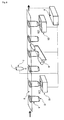
Nachfolgend soll die Erfindung anhand von Ausführungsbeispielen im Zusammenhang mit den Zeichnungen näher erläutert werden. Dabei sind nur die für das Verständnis der Erfindung wesentlichen Elemente dargestellt. Es zeigt
Figur 1- ein Reaktionsgefäß mit einem nachträglich auf der äußeren Man- telfläche aufgebauten Transponder;
Figur 2- ein nicht erfindungsgemäßes Fläschchen mit einem in den Boden eingebrachten Transpon- der in Disk-Bauform;
Figur 3- die Herstellung einer RFID-Flasche mit Hilfe eines selbstkieben- den Transponderhalbzeugs: a) Selbstklebendes Transponderhalb- zeug mit offener Spule, b) Aufkleben des Transponderhalbzeugs auf die Flasche, c) fertige RFID-Flasche;
- Figur 4
- einen RFID-Becher bestehend aus zwei ineinander gesteckten Bechern, wobei der Transponder auf der äußeren Mantelfläche des inneren Bechers aufgebaut ist;
- Figur 5
- die Herstellung eines nicht erfindungsgemäßen RFID-Bechers im Tiefziehverfahren: a) Auf- bau des Transponders mit ebenen Trägerfolien, b) Laminieren und Tiefziehen;
Figur 6- den Einsatz von nicht erfindungsgemäßen RFID-Probenröhrchen in einer automatischen Synthese- bzw. Analysestation;
- Figur 7
- eine nicht erfindungsgemäße RFID-Flasche- mit einer Dipolantenne für den Betrieb im Ult- rahochfrequenz-Bereich nach einem weiteren Ausführungsbeispiel der Erfindung; und
- Figur 8
- die Herstellung einer nicht erfindungsgemäßen RFID-Flasche mit einer als offene Spule aus- gebildeten Dipolantenne: a) Selbstklebender Träger mit Transpon- der und Dipolantenne, b) Aufkleben des Trägers auf die Flasche, c) fertige RFID-Flasche.
- FIG. 1
- a reaction vessel with a transponder constructed subsequently on the outer shell surface;
- FIG. 2
- a vial not according to the invention with a transponder incorporated in the bottom in disk form;
- FIG. 3
- the production of an RFID bottle by means of a semi-finished transponder semi-finished product: a) self-adhesive transponder semi-finished product with open coil, b) gluing of the transponder semi-finished product to the bottle, c) finished RFID bottle;
- FIG. 4
- an RFID cup consisting of two nested cups, wherein the transponder is constructed on the outer surface of the inner cup;
- FIG. 5
- the production of a non-inventive RFID cup in the deep drawing process: a) construction of the transponder with flat carrier foils, b) lamination and thermoforming;
- FIG. 6
- the use of non-inventive RFID sample tube in an automatic synthesis or analysis station;
- FIG. 7
- a non-inventive RFID bottle with a dipole antenna for operation in the ultrahigh-frequency range according to a further embodiment of the invention; and
- FIG. 8
- the production of a non-inventive RFID bottle with a dipole antenna formed as an open coil: a) self-adhesive carrier with transponder and dipole antenna, b) sticking of the carrier on the bottle, c) finished RFID bottle.
Zunächst wird mit Bezug auf die
In
Dieses Gefäß umfasst neben einem erfindungsgemäß relevanten zylinderförmigen Hauptabschnitt 12, der der Handhabung des Reaktionsgefäßes dient, einen Boden 11 mit Abschrägungen im Bodenbereich 111, einen Deckel 13 mit Deckelhalterung 131 (Scharnier) und Schnappverschluss 132.This vessel comprises, in addition to a cylinder-shaped
Auf die Mantelfläche des zylinderförmigen Abschnitts 12 des Gefäßes wird der Spulendraht der Transponderspule 22 mit einer automatischen Wickelmaschine gewickelt. Vorzugsweise sind die verwendeten Kupferdrähte neben dem üblichen Isolationslack mit einer zusätzlichen Schicht niedrigschmelzenden Backlacks versehen. Während des Wickelvorgangs wird das Gefäß auf die Schmelztemperatur des Backlacks erhitzt. Dieser schmilzt während des Wickelvorgangs, wodurch die einzelnen Windungen der Transponderspule miteinander verkleben. Auf diese Weise wird die mechanische Stabilität der Spule bereits vor der am Ende des Produktionsprozesses aufzubringenden Schutzschicht gewährleistet. Nach dem Wickeln der Spule stehen zur Kontaktierung des Transponderchips 21 zwei Varianten zur Auswahl: Erlauben die mechanischen Stabilitätsanforderungen und die Größe des Reaktionsgefäßes die Verwendung von sehr dünnen Spulendrähten (<= 50 µm), so kann der Draht direkt auf den Transponderchip gebondet werden. Alternativ wird ein Transpondermodul (Transponderchip, der auf einem Träger bzw. in einem Gehäuse fixiert ist) eingesetzt. Die Anschlüsse der Spule werden mit einem Punktschweißgerät an die Anschlussflächen des Transpondermoduls angeschweißt. Abschließend wird der gesamte Transponderaufbau mit einer Schutzschicht 3 aus Kunststoff überzogen. Die Schutzschicht wird dabei entweder durch Gießen bzw. Sprühen noch auf der Wickelmaschine oder durch Eintauchen des Gefäßes in verflüssigten Kunststoff aufgetragen.On the lateral surface of the
In weiteren Ausführungsformen eines Probenröhrchens mit Transponder wird die Antennenspule nicht aus Draht gewickelt, sondern entweder
- aus einer flächigen leitfähigen Beschichtung der Außenwand des Probenröhrchens - bevorzugt einer Kupferbeschichtung - mit Hilfe einer Maske herausgeätzt,
- aus einem leitfähigen Polymer, bevorzugt einem Silberleitkleber mit Epoxydharz, hergestellt, das bei rotierendem Probenröhrchen aufgetragen wird oder
- aus einer leitfähigen Paste (bekannt als: polymer thick film - PTF) hergestellt, die auf die Mantelfläche aufgedruckt wird.
- from a planar conductive coating of the outer wall of the sample tube - preferably a copper coating - etched out with the aid of a mask,
- made of a conductive polymer, preferably a silver conductive adhesive with epoxy resin, which is applied with a rotating sample tube or
- made of a conductive paste (known as polymer thick film - PTF), which is printed on the lateral surface.
Der Transponder in Disk-Bauform beinhaltet neben dem Transponderchip eine kreisringförmige Antenne, die nahe der Mantelfläche innerhalb des scheibenförmigen Spritzgussgehäuses verläuft. Durch die koaxiale Anordnung von Disk-Transponder und zylinderförmiger Flasche sind folgende erfindungsgemäße Vorteile gewährleistet: einheitliche Orientierung der Transponderspulen bei parallel stehenden Flaschen, Sicherstellung eines Mindestabstands (= Flaschendurchmesser) der Spulenachsen, eine relativ zum Gefäß große Spulenfläche und damit hoher Energieübertragung bzw. Reichweite. Weitere Vorteile dieser Anordnung sind die geschützte Position und damit stabile Fixierung des Transponders in der Aussparung des Bodens, die Möglichkeit der Anbringung eines Transponders an dünnwandige und kleine Gefäße sowie Gefäße mit kleinen Krümmungsradien.The transponder in disk design contains, in addition to the transponder chip, an annular antenna which runs close to the lateral surface within the disk-shaped injection-molded housing. Due to the coaxial arrangement of Disk transponder and cylinder-shaped bottle, the following advantages of the invention are ensured: uniform orientation of the transponder coils in parallel bottles, ensuring a minimum distance (= bottle diameter) of the coil axes, a relative to the vessel large coil surface and thus high energy transfer and range. Further advantages of this arrangement are the protected position and thus stable fixation of the transponder in the recess of the soil, the possibility of attaching a transponder to thin-walled and small vessels and vessels with small radii of curvature.
Eine weitere nicht erfindungsgemäße Ausführungsform mit vergleichbaren Vorteilen ist eine Petri-Schale (ein flaches zylinderförmiges Gefäß) auf deren Boden oder Deckel von außen ein Smart-Label, d.h. ein selbstklebendes Transponderetikett, dergestalt aufgeklebt wird, dass die Transponderspule um die Zylinderachse herum verläuft. Bevorzugt wird dabei ein kreisförmiges Smart-Label konzentrisch aufgeklebt, so dass die Zylinderachse durch die Fläche der Transponderspule hindurchtritt.Another non-inventive embodiment with comparable advantages is a petri dish (a flat cylindrical vessel) on its bottom or lid from the outside a smart label, i. a self-adhesive transponder label adhered such that the transponder coil extends around the cylinder axis. Preferably, a circular smart label is glued concentrically, so that the cylinder axis passes through the surface of the transponder coil.
In
Der Transponder 2 bestehend aus Chip 21 und Spule 22 wird, anlog wie anhand
Anschließend werden die Becher ineinandergesteckt und miteinander verschweißt. Je nach Stabilitätsanforderungen geschieht das Verschweißen vollflächig oder nur im Bereich des Deckelflanschs (14 und 34) und bei Bedarf im Bodenbereich (11 und 31).Then the cups are plugged into each other and welded together. Depending on the stability requirements welding takes place over the entire surface or only in the region of the cover flange (14 and 34) and, if necessary, in the bottom region (11 and 31).
Anhand der
Eine Chipkarte ist typischerweise aus vier Folien aufgebaut: zwei Inletfolien, davon eine Trägerfolie 18, auf der der Transponder 2 aufgebaut wird, und eine im Bereich 171 des Chips 21 ausgestanzte Zwischenfolie 17, sowie zwei Deckfolien (Overlayfolien 16, 19), welche die Außenseite der Karte bilden. Während zur Herstellung von Chipkarten möglichst steife Kunststoffe eingesetzt werden, werden für die Herstellung erfindungsgemäßer RFID-Becher zum Tiefziehen geeignete, thermisch leicht formbare Kunststoffe bevorzugt. Dabei bietet sich an, Kunststoffe wie Polyethylen (PE), Polyethylenterephthalat (PET), Polyvinylchlorid (PVC), Polystyrol (PS) und insbesondere Polypropylen (PP) einzusetzen.A chip card is typically composed of four films: two inlet foils, one of which is a
Nachdem der Transponder aufgebaut und die Folien passgenau übereinander gelegt sind, werden die Folien laminiert, d. h. bei erhöhter Temperatur (T = ca. 100 - 200°C) und hohem Druck (p = 20 -120 kg/cm2) in einen weichelastischen Zustand gebracht und miteinander verbacken. Anschließend werden die verbackenen Folien insgesamt im Tiefziehverfahren zum erfindungsgemäßen Becher geformt (
Nach dem Laminieren, Tiefziehen und Auskühlen werden die einzelnen geformten RFID-Becher 1 aus dem Mehrfachnutzen-Bogen ausgestanzt (
Bei einer nicht erfindungsgemäßen Variante des hier beschriebenen RFID-Bechers wird lediglich der Boden aus den vier Folien, die den Transponder enthalten, laminiert. Der restliche Becher besteht dann lediglich aus einer Folie, die durch Tiefziehen in Form gebracht wird.In a non-inventive variant of the RFID cup described here, only the bottom of the four films containing the transponder is laminated. The rest of the cup then consists only of a film which is brought into shape by deep drawing.
Die Antennen der Transponderauslesegeräte 511 und 521 sind in der Nähe jeweils eines Haltepunkts der Transponder 2 so angeordnet, dass deren Magnetfeldlinien am jeweiligen Haltepunkt parallel zur Spulenachse eines dort vorhandenen Transponders verlaufen und eine selektive Auslesung dieses Transponders ermöglicht wird.The antennas of the
Durch die Anordnung mehrerer Prozessierungsstationen hintereinander, gegebenenfalls ergänzt durch (temperierte) Zwischenlager und Sortiereinheiten, können komplexe Synthesen und Analysen durchgeführt werden. Das ganze Prozessierungssystem wird über eine zentrale Datenverarbeitungseinheit 9 gesteuert.The arrangement of several processing stations in a row, optionally supplemented by (tempered) intermediate storage and sorting units, complex syntheses and analyzes can be performed. The whole Processing system is controlled by a central data processing unit 9.
Auf dem Transponder 2 eines jeden Probenröhrchens 1 können folgende Daten abgelegt werden: Identifikationsnummer des Probenröhrchens, Spezifikation des Inhalts, Herkunft des Inhalts, Patientendaten bei klinischen Anwendungen, durchgeführte und durchzuführende Verarbeitungsschritte, durchlaufene und zu durchlaufende Verarbeitungsstationen, Aufenthaltsorte und Zeiten, physikalische Messgrößen, z.B. Temperatur, Druck, Füllstand, Beschleunigung, insbesondere von einem in den Transponder integrierten Sensor, Herstellungsdatum des Inhalts und/oder des Behälters sowie Bedienungsanleitung oder Steuerungscode für die Prozessierungseinheit.The following data may be stored on the
Die Informationen dienen insbesondere der eindeutigen Kennzeichnung der Substanzen in den Probenröhrchen, der Steuerung sowie Dokumentation der Produktions- bzw. Analyseschritte und damit der Rückverfolgbarkeit bzw. Qualitätssicherung der Prozesse.The information is used in particular for the clear identification of the substances in the sample tubes, the control and documentation of the production and analysis steps and thus the traceability and quality assurance of the processes.
In den
Der Vorteil dieser Anordnung besteht darin, dass bei parallel angeordneten (aufgestellten) Flaschen die jeweiligen Antennen mit einheitlicher Orientierung ausgerichtet sind und damit mit einer einheitlichen, parallelen Orientierung der Antenne des Lesegeräts bevorzugt ausgelesen werden können. Auf einer Förderstrecke quer zur Flaschenachse ist damit auch eine definierte selektive Auslesung des jeweils in der Hauptstrahlrichtung befindlichen Transponders möglich. Die Bevorzugung eines entfernteren Transponders (Fehllesung) aufgrund unterschiedlicher Orientierungen ist damit ausgeschlossen.The advantage of this arrangement is that in parallel (erected) bottles, the respective antennas are aligned with a uniform orientation and thus can be preferably read with a uniform, parallel orientation of the antenna of the reader. On a conveyor line transverse to the bottle axis so that a defined selective readout of each located in the main beam direction transponder is possible. The preference of a remote transponder (incorrect reading) due to different orientations is thus excluded.
Bevorzugt umfasst dabei der Behälter 1 und/oder die Förderstrecke ein Mittel, das ein Verdrehen des Behälters um die eigene Achse verhindert.Preferably, the
Alternativ oder zusätzlich können der Behälter und/oder die Förderstrecke ein Mittel umfassen, das einen Mindestabstand der Mantelflächen benachbarter Flaschen gewährleistet.Alternatively or additionally, the container and / or the conveying path may comprise a means which ensures a minimum distance of the lateral surfaces of adjacent bottles.
Während die Erfindung insbesondere mit Bezug auf bevorzugte Ausführungsbeispiele gezeigt und beschrieben worden ist, versteht sich für den Fachmann, dass Änderungen in Gestalt und Einzelheiten gemacht werden können, ohne von dem Umfang der Erfindung abzuweichen. Dementsprechend soll die Offenbarung der vorliegenden Erfindung nicht einschränkend sein. Statt dessen soll die Offenbarung der vorliegenden Erfindung den Umfang der Erfindung veranschaulichen, der in den nachfolgenden Ansprüchen dargelegt ist.While the invention has been particularly shown and described with reference to preferred embodiments, it will be understood by those skilled in the art that changes in form and detail may be made without departing from the scope of the invention. Accordingly, the disclosure of the present invention is not intended to be limiting. Instead, the disclosure of the present invention is intended to illustrate the scope of the invention, which is set forth in the following claims.
Claims (25)
- A system for marking, identifying and tracking substances or containers, comprising:- a plurality of homogeneous containers for transporting and storing substances,- which are each provided with a transponder for radio frequency identification, and- which, in the system, are standing close together or are even touching each other,- wherein each of the homogeneous containers- - exhibits a substantially cylinder-shaped main section having a curved lateral surface, and- - the transponder includes an electronic memory and, as a coupling element, an antenna coil, wherein- - the antenna coil is disposed in or on a wall surface of the container and with its axis parallel to the cylinder axis of the main section, and the antenna coil is disposed in the cylinder-shaped main section of the container on the lateral surface of the cylinder and exhibits one or more windings around the cylinder axis,- and comprising for the transponders of the containers, one or more readout devices that are disposed at locations at which an identification or processing of the substances or containers is to take place, and past which the containers are directed with the same orientation of their cylinder axis.
- The system according to claim 1, characterized in that the antenna coil of the containers is disposed in or on a wall surface of the container such that the cylinder axis of the main section passes through the area of the antenna coil (22).
- The system according to claim 1 or 2, characterized in that the cylinder-shaped main section of the containers constitutes a receiving region that receives the substances to be transported or stored.
- The system according to claim 1 or 2, characterized in that the cylinder-shaped main section of the containers is connected with a conically tapering receiving region that receives the substances to be transported or stored.
- The system according to one of the preceding claims, characterized in that the cylinder-shaped main section of the containers constitutes a handling region that serves the handling, such as the transportation or storage, of the container.
- The system according to one of the preceding claims, characterized in that the cylinder-shaped main section of the containers exhibits no edges.
- The system according to one of the preceding claims, characterized in that the cylinder-shaped main section of the containers takes up more than 50%, especially more than 70% of the dimension of the container in the direction of the cylinder axis.
- The system according to one of the preceding claims, characterized in that the containers consist of a plastic material such as PE, PP, PS, PET, ABS, an epoxide resin, a molding compound or IC sealing compound, or of glass.
- The system according to one of the preceding claims, characterized in that the transponder of the containers is embedded under the surface of the container in plastic, glass or a lacquer layer.
- The system according to one of the preceding claims, characterized in that the containers are formed to be resistant to liquids, chemicals, mechanical stresses, especially abrasion, or sterilization or autoclaving processes.
- The system according to one of the preceding claims, characterized in that the transponder of the containers is designed for an operating frequency between 9 and 135 kHz, preferably between 100 and 135 kHz.
- The system according to one of claims 1 to 10, characterized in that the transponder of the containers is designed for an operating frequency in the ISM frequency range, especially for an operating frequency around 6.78 MHz, 13.56 MHz, 27.125 MHz, 40.68 MHz, 433.92 MHz, 869.0 MHz, 915.0 MHz, 2.45 GHz, 5.8 GHz or 24.125 GHz, and particularly preferably for an operating frequency around 13.56 MHz.
- The system according to one of the preceding claims, characterized in that the containers are closable with an associated lid, especially with a seal lid or screw top.
- The system according to one of the preceding claims, characterized in that the containers are (returnable) bottles, recycling containers or cups manufactured in the deep drawing method.
- The system according to one of the preceding claims, characterized in that the containers are reaction vessels, such as a sample tube, an Eppendorf tube or a Petri dish, especially for clinical and biochemical labs, or sample vessels within a microtiter plate.
- The system according to one of the preceding claims, characterized in that the electronic memory of the containers contains data, such as an identification number, specification of the contents, origin of the contents, patient data for clinical applications, processing steps performed or to be performed, processing stations passed through or to be passed through, staging points and times, physical measurands, such as temperature, pressure, fill level and acceleration, that stem especially from a sensor integrated into the transponder, manufacturing date of the contents and/or of the containers, and operating manual or control code for processing systems.
- The system according to one of the preceding claims, characterized in that the electronic memory of the containers is a read-only memory.
- The system according to one of claims 1 to 49, characterized in that the electronic memory of the containers is a rewritable memory.
- The system according to one of the preceding claims, characterized in that the containers comprise a rotation limiter that, on a conveyance path, prevents the rotation of the containers about their own axis.
- The system according to one of the preceding claims, characterized in that the containers comprise a spacer that ensures a preselected minimum spacing of adjacent containers on a conveyance path.
- A method for automatically marking, identifying and tracking substances or containers, having the following method steps:- providing a system in which homogeneous containers are standing close together or are even touching each other, according to one of claims 1 to 20,- writing an unambiguous identification code to the electronic memory of the transponder of the containers,- filling the substances into the containers, and- reading out the identification code when a container is located at one of the readout devices.
- The method according to claim 21, characterized in that information about the substance to be filled or the filled substance is written to the electronic memory.
- The method according to claim 21 or 22, characterized in that, when the container is located at one of the readout devices, a time code, location code and/or data pertaining to the substance processing is written to the electronic memory.
- The method according to one of claims 21 to 23, characterized in that, when writing to and/or reading out the electronic memory, a secure data transmission is carried out, especially through identification or authorization protocols.
- The method according to one of claims 21 to 24, characterized in that a plurality of homogeneous containers is labeled and filled with substances, and all containers are directed past the readout device(s) with the same orientation of their cylinder axis.
Applications Claiming Priority (2)
| Application Number | Priority Date | Filing Date | Title |
|---|---|---|---|
| DE102004061633A DE102004061633A1 (en) | 2004-12-17 | 2004-12-17 | Container with transponder |
| PCT/EP2005/013478 WO2006066787A1 (en) | 2004-12-17 | 2005-12-15 | Container with transponder |
Publications (3)
| Publication Number | Publication Date |
|---|---|
| EP1838589A1 EP1838589A1 (en) | 2007-10-03 |
| EP1838589B1 true EP1838589B1 (en) | 2011-04-20 |
| EP1838589B8 EP1838589B8 (en) | 2011-09-14 |
Family
ID=35789373
Family Applications (1)
| Application Number | Title | Priority Date | Filing Date |
|---|---|---|---|
| EP05819232A Not-in-force EP1838589B8 (en) | 2004-12-17 | 2005-12-15 | System and method for automatic marking, identification and tracing of substances or containers |
Country Status (5)
| Country | Link |
|---|---|
| US (1) | US20100032437A1 (en) |
| EP (1) | EP1838589B8 (en) |
| AT (1) | ATE506271T1 (en) |
| DE (3) | DE102004061633A1 (en) |
| WO (1) | WO2006066787A1 (en) |
Cited By (5)
| Publication number | Priority date | Publication date | Assignee | Title |
|---|---|---|---|---|
| DE102011084453A1 (en) | 2011-10-13 | 2013-04-18 | Krones Aktiengesellschaft | Device for checking operability of inspection unit of beverage bottles in production line, has interrogation unit identifying test container based on marks, where device is formed to assign reference values to associated container |
| DE102014105548A1 (en) * | 2014-04-17 | 2015-10-22 | Krones Ag | Inspection device for containers and / or containers and computer-implemented method for inspecting containers and / or containers |
| DE102017106538A1 (en) * | 2017-03-27 | 2018-09-27 | Gazwan Avakhti | beverage containers |
| EP3410386A1 (en) | 2017-05-31 | 2018-12-05 | Greiner Bio-One GmbH | Method for data management in health care |
| DE102012204277B4 (en) | 2012-03-19 | 2023-02-09 | Krones Ag | Device and method for checking container inspection units |
Families Citing this family (50)
| Publication number | Priority date | Publication date | Assignee | Title |
|---|---|---|---|---|
| US10010371B2 (en) * | 2005-05-31 | 2018-07-03 | Aprovix Ab | Sampling system |
| GB2433926A (en) * | 2005-12-22 | 2007-07-11 | Lifescan Scotland Inc | Container with RFID for storing calibration information |
| US7586417B2 (en) | 2006-11-10 | 2009-09-08 | Rexam Healthcare Packaging Inc. | RFID insert with disable feature and container that includes such an insert |
| CA2680655C (en) * | 2007-03-19 | 2015-06-30 | Csp Technologies, Inc. | Method for incorporating an anti-counterfeiting device into a multi-walled container and the multi-walled container containing such device |
| DE102008012505B4 (en) | 2008-03-04 | 2019-02-21 | Krones Aktiengesellschaft | Stretch blow molding machine with printing device |
| DE102008021490A1 (en) * | 2008-04-29 | 2009-11-05 | Fachhochschule Münster | Sterilization process monitoring method for e.g. medical instrument, involves transferring identification data of articles that are sterilized, and storing time and temperature measurement for sterilization |
| US8976029B1 (en) * | 2008-07-10 | 2015-03-10 | Annette Cote McTigue | Product management system |
| JP5256935B2 (en) * | 2008-08-26 | 2013-08-07 | 富士通株式会社 | ID tag manufacturing method |
| DE202008014618U1 (en) * | 2008-11-04 | 2010-03-25 | Hirschmann Laborgeräte GmbH & Co. KG | Vessel for containing chemical, biochemical, medical or pharmaceutical components or samples and system for identifying such a vessel |
| GB2467185A (en) * | 2009-01-27 | 2010-07-28 | Navigator Systems Ltd | Antenna Arrangement of RFID Tag |
| IT1396263B1 (en) * | 2009-09-22 | 2012-11-16 | Fresenius Kabi Italia S R L | IDENTIFICATION AND TRACEABILITY TECHNIQUES OF THE BLOOD BAGS DURING THE TRANSFUSION PROCESS. |
| FR2957536A1 (en) * | 2010-03-18 | 2011-09-23 | Sas Laboratoire | Test tubes for containing e.g. blood, to be analyzed in laboratory, has reading and/or writing unit that reads and/or writes identifier stored and/or to be stored in chip, where unit is located in circulation path of tube |
| US8852532B2 (en) | 2010-06-18 | 2014-10-07 | Roche Diagnostics Operations, Inc. | G-force sensitive label and corresponding sample tube, method and analytical system |
| USD742693S1 (en) | 2011-10-04 | 2015-11-10 | Alicia Spagnola | Combination electronic storage medium and drinking cup |
| DE102011088144A1 (en) * | 2011-12-09 | 2013-06-13 | Robert Bosch Gmbh | Device for carrying out a centrifuging process, container device and method for carrying out a centrifuging process |
| DE102011120859A1 (en) * | 2011-12-13 | 2013-06-13 | Felix Schoeller Supply Chain Technologies Gmbh & Co. Kg | Transponder arrangement for integration in an object |
| ES2376436B1 (en) * | 2012-01-31 | 2012-11-19 | Grifols, S.A. | CONTAINER OF PRODUCTS DERIVED FROM THE BLOOD. |
| US9488538B2 (en) * | 2012-01-31 | 2016-11-08 | Smart Skin Technologies, Inc. | Pressure mapping and orientation sensing system |
| EP2623206A1 (en) * | 2012-02-01 | 2013-08-07 | Baumer Electric AG | Centrifuge |
| JP5639607B2 (en) * | 2012-02-27 | 2014-12-10 | 三智商事株式会社 | Wireless IC tag |
| JP5639606B2 (en) | 2012-02-27 | 2014-12-10 | 三智商事株式会社 | Wireless IC tag |
| DE102012102885A1 (en) | 2012-04-03 | 2013-10-10 | Reinhausen Plasma Gmbh | Container for powder, method for marking a container for powder and apparatus for using powder from the container |
| US9439590B2 (en) * | 2013-03-13 | 2016-09-13 | George S. Cembrowski | Method and apparatus for blood collection |
| US11241178B2 (en) | 2013-03-13 | 2022-02-08 | George S. Cembrowski | Method and apparatus for inversion detection |
| DE102013103992A1 (en) | 2013-04-19 | 2014-10-23 | Krones Ag | Test container for testing inspection equipment |
| US20140345534A1 (en) * | 2013-05-27 | 2014-11-27 | Hana Micron America Inc. | Livestock Feeder-Embedded RFID Antenna Apparatus |
| AT514661A1 (en) * | 2013-07-25 | 2015-02-15 | Seibersdorf Labor Gmbh | container |
| US10377623B2 (en) | 2014-06-27 | 2019-08-13 | Neurones Vision Inc. | System and method for dispensing and sale of bulk products |
| CN104777293A (en) * | 2015-04-05 | 2015-07-15 | 浙江大学 | Detection device and detection method |
| US20160364640A1 (en) * | 2015-06-09 | 2016-12-15 | Promega Corporation | Radio frequency identification techniques in an ultra-low temperature environment |
| DE102016120792A1 (en) * | 2016-04-19 | 2017-10-19 | Rastal Gmbh & Co Kg | serving system |
| US9863989B1 (en) * | 2016-08-18 | 2018-01-09 | The United States Of America As Represented By Secretary Of The Navy | Current probe fed dipole array on dielectric water bottle with brine water loading |
| CH712996A1 (en) * | 2016-09-30 | 2018-04-13 | Hoffmann Neopac Ag | Tube and tube body with an electronic device. |
| US20190287089A1 (en) * | 2017-07-07 | 2019-09-19 | Instream Water, Inc. | Beverage kiosk apparatus, system, and method |
| WO2019018837A1 (en) * | 2017-07-21 | 2019-01-24 | Avery Dennison Retail Information Services Llc | Rfid vial tracking with rfid inlay |
| DE102017120214A1 (en) * | 2017-09-01 | 2019-03-07 | Krones Ag | Plastic preform with RFID tag |
| EP3501660A1 (en) * | 2017-12-19 | 2019-06-26 | Antonio Pinto | Method and device for the separation of substances by centrifugation |
| US20210147212A1 (en) * | 2018-02-02 | 2021-05-20 | Conopco, Inc., D/B/A Unilever | Sustainable methods and devices for automated dosing of a laundry product |
| EA202091899A1 (en) | 2018-02-13 | 2020-11-02 | Карлсберг Брюэриз А/С | BEVERAGE FILLING SYSTEM CONTAINING SINGLE-USE Squeezable Barrels |
| DE102018207425A1 (en) * | 2018-05-14 | 2019-11-14 | Fritz Schäfer GmbH | A trashcan equipped with a transponder and a stopper equipped with a transponder for use in a garbage bin |
| WO2019246342A1 (en) * | 2018-06-20 | 2019-12-26 | Amcor Rigid Plastics Usa, Llc | Refillable pet bottle codification for container lifecycle traceability |
| DE102018215035A1 (en) * | 2018-09-04 | 2020-03-05 | Rhenoflex Gmbh | Stiffening element and method for producing a stiffening element |
| WO2020181375A1 (en) * | 2019-03-13 | 2020-09-17 | Motryx Inc. | Sensor device for detecting transport parameters and method of making the same |
| DE102019208645A1 (en) * | 2019-06-13 | 2020-12-17 | Krones Ag | Process for the automatic control of a packing process, control system and placeholder for a container or an outer packaging for containers |
| DE102019124948A1 (en) * | 2019-09-17 | 2021-03-18 | ZiVo Engineering GmbH | Method and apparatus for operating a plant breeding and sales system |
| CN110781995A (en) * | 2019-10-30 | 2020-02-11 | 浙江悦和科技有限公司 | Method for manufacturing reaction vessel and reaction vessel |
| US11910982B2 (en) | 2019-11-01 | 2024-02-27 | Conopco Inc. | Recyclable auto-dosing container |
| EP4275146A1 (en) | 2021-01-10 | 2023-11-15 | Kapoor, Puneet | Article with embedded rfid labels and methods of manufacture thereof |
| WO2022175221A1 (en) * | 2021-02-16 | 2022-08-25 | F. Hoffmann-La Roche Ag | Reaction vessel |
| CN117553445B (en) * | 2024-01-09 | 2024-03-22 | 浙江拓感科技有限公司 | Infrared detector quick start integrated refrigerator subassembly |
Family Cites Families (30)
| Publication number | Priority date | Publication date | Assignee | Title |
|---|---|---|---|---|
| DE2758437C2 (en) * | 1977-12-28 | 1984-02-02 | Ultrakust Gerätebau GmbH & Co KG, 8375 Ruhmannsfelden | Milk sample bottle |
| US4210900A (en) * | 1978-08-16 | 1980-07-01 | Honeywell Inc. | Surface acoustic wave code reader |
| DE4313049C2 (en) | 1993-04-21 | 1996-05-15 | Michael L Hoeffgen | Shipping container |
| US5491483A (en) | 1994-01-05 | 1996-02-13 | Texas Instruments Incorporated | Single loop transponder system and method |
| DE9407696U1 (en) | 1994-05-10 | 1994-09-01 | Philipp Christian Dr Ing | container |
| GB9422082D0 (en) * | 1994-11-02 | 1994-12-21 | Zeneca Ltd | Reservoirs and delivery devices |
| DE4439914C2 (en) * | 1994-11-08 | 2002-06-06 | Eltec Mueller Gmbh & Co Kg | bottle |
| US6153425A (en) * | 1995-07-13 | 2000-11-28 | Xtrana, Inc. | Self-contained device integrating nucleic acid extraction, amplification and detection |
| EP0782214B1 (en) * | 1995-12-22 | 2004-10-06 | Texas Instruments France | Ring antennas for resonant cicuits |
| DE19645892C2 (en) * | 1996-11-07 | 1999-02-18 | Eppendorf Geraetebau Netheler | Lid jar |
| US6136274A (en) * | 1996-10-07 | 2000-10-24 | Irori | Matrices with memories in automated drug discovery and units therefor |
| FR2760998B1 (en) * | 1997-03-21 | 1999-05-21 | Equisecurite Sa | METHOD OF INCLUDING AN ELECTRONIC LABEL IN AN OBJECT MADE OF PLASTIC, AT THE TIME OF THE MANUFACTURE OF THE OBJECT |
| US6538569B1 (en) * | 1998-10-30 | 2003-03-25 | The Goodyear Tire & Rubber Company | Container with sensor |
| FR2791035B1 (en) * | 1999-03-19 | 2001-07-27 | Allibert Equipement | PROCESS FOR PACKAGING AN ELECTRONIC LABEL, CORRESPONDING PLASTIC LABEL AND PIECE |
| DE29910452U1 (en) * | 1999-06-15 | 1999-08-26 | Krones Ag | Device for checking the functionality of bottle inspection machines and a test bottle suitable for this |
| EP1083519A3 (en) * | 1999-09-09 | 2002-01-30 | Supersensor (Proprietary) Limited | Method of mounting RF transponders on containers |
| ES2195940T3 (en) | 1999-10-20 | 2003-12-16 | Ifco Systems Gmbh | CONTAINER FOLLOW-UP SYSTEM AND REUSABLE CONTAINER INCLUDING A TRANSPONDER. |
| GB0013619D0 (en) * | 2000-06-06 | 2000-07-26 | Glaxo Group Ltd | Sample container |
| DE20010351U1 (en) * | 2000-06-09 | 2000-08-31 | Flexchip Ag | Bottle label |
| US6483473B1 (en) * | 2000-07-18 | 2002-11-19 | Marconi Communications Inc. | Wireless communication device and method |
| JP2002185358A (en) | 2000-11-24 | 2002-06-28 | Supersensor Pty Ltd | Method for fitting rf transponder to container |
| DE10246777A1 (en) * | 2002-03-21 | 2003-10-02 | Endress & Hauser Wetzer Gmbh | Device for identifying sample container and/or for preparing information connected with sample container comprises electronic label assigned to container |
| DE10253567A1 (en) * | 2002-11-15 | 2004-05-27 | Linpac Plastics Gmbh | Storage means, especially shell |
| DE10257923A1 (en) * | 2002-12-11 | 2004-06-24 | BROSOW, Jörgen | Bottle corking device for wine etc. has electronic transponder circuit producing and storing identification from injected scan signal |
| US6959229B2 (en) | 2003-03-07 | 2005-10-25 | Sdi Industries, Inc. | RFID control system |
| DE10310238A1 (en) | 2003-03-08 | 2004-09-23 | Bekuplast Kunststoffverarbeitungs-Gmbh | Plastic container with integrated transponder |
| US7017807B2 (en) * | 2003-09-08 | 2006-03-28 | Francis M. Claessens | Apparatus and method for detecting tampering with containers and preventing counterfeiting thereof |
| US7298243B2 (en) * | 2003-11-12 | 2007-11-20 | Rsa Security Inc. | Radio frequency identification system with privacy policy implementation based on device classification |
| FR2862947B1 (en) * | 2003-11-28 | 2010-01-01 | Cebal Sas | FLEXIBLE TUBE WITH ELECTRONIC COMPONENT |
| US7187286B2 (en) * | 2004-03-19 | 2007-03-06 | Applera Corporation | Methods and systems for using RFID in biological field |
-
2004
- 2004-12-17 DE DE102004061633A patent/DE102004061633A1/en not_active Withdrawn
-
2005
- 2005-12-15 DE DE202005021951U patent/DE202005021951U1/en not_active Expired - Lifetime
- 2005-12-15 AT AT05819232T patent/ATE506271T1/en active
- 2005-12-15 US US11/721,931 patent/US20100032437A1/en not_active Abandoned
- 2005-12-15 DE DE502005011294T patent/DE502005011294D1/en active Active
- 2005-12-15 WO PCT/EP2005/013478 patent/WO2006066787A1/en active Application Filing
- 2005-12-15 EP EP05819232A patent/EP1838589B8/en not_active Not-in-force
Cited By (7)
| Publication number | Priority date | Publication date | Assignee | Title |
|---|---|---|---|---|
| DE102011084453A1 (en) | 2011-10-13 | 2013-04-18 | Krones Aktiengesellschaft | Device for checking operability of inspection unit of beverage bottles in production line, has interrogation unit identifying test container based on marks, where device is formed to assign reference values to associated container |
| DE102011084453B4 (en) | 2011-10-13 | 2021-12-02 | Krones Aktiengesellschaft | Device and method for checking container inspection units |
| DE102012204277B4 (en) | 2012-03-19 | 2023-02-09 | Krones Ag | Device and method for checking container inspection units |
| DE102014105548A1 (en) * | 2014-04-17 | 2015-10-22 | Krones Ag | Inspection device for containers and / or containers and computer-implemented method for inspecting containers and / or containers |
| DE102017106538A1 (en) * | 2017-03-27 | 2018-09-27 | Gazwan Avakhti | beverage containers |
| EP3410386A1 (en) | 2017-05-31 | 2018-12-05 | Greiner Bio-One GmbH | Method for data management in health care |
| WO2018219945A1 (en) | 2017-05-31 | 2018-12-06 | Greiner Bio-One Gmbh | Method for managing data in the field of health |
Also Published As
| Publication number | Publication date |
|---|---|
| EP1838589B8 (en) | 2011-09-14 |
| WO2006066787A1 (en) | 2006-06-29 |
| DE202005021951U1 (en) | 2012-01-19 |
| US20100032437A1 (en) | 2010-02-11 |
| DE502005011294D1 (en) | 2011-06-01 |
| DE102004061633A1 (en) | 2006-06-29 |
| EP1838589A1 (en) | 2007-10-03 |
| ATE506271T1 (en) | 2011-05-15 |
Similar Documents
| Publication | Publication Date | Title |
|---|---|---|
| EP1838589B1 (en) | System and method for automatic marking, identification and tracing of substances or containers | |
| DE112006002996B4 (en) | Method and system for article tracking with brands | |
| DE4439914C2 (en) | bottle | |
| DE60131657T2 (en) | WIRELESS COMMUNICATION DEVICE AND METHOD | |
| US7070053B1 (en) | System, method, and apparatuses for maintaining, tracking, transporting and identifying the integrity of a disposable specimen container with a re-usable transponder | |
| DE102006010159A1 (en) | Electronic label and method for monitoring good | |
| EP2102796A1 (en) | Method and system for monitoring a container | |
| DE102006057644A1 (en) | Container for shipping objects and method for producing the containers | |
| JP2006062716A (en) | Cap type rf-id and rf-id system using the same | |
| DE102006057645A1 (en) | Sensor transponder unit and method of operation | |
| EP1491317B1 (en) | Method for producing a container with a data carrier and container with a data carrier | |
| WO2006100283A1 (en) | Hand-held tool or accessory for a hand-held tool | |
| EP1466298B1 (en) | Transponder label | |
| EP1001265A2 (en) | Sampling bottle | |
| DE102005026559A1 (en) | Installation assembly for radio frequency identification transponder has plastic foam separation layer | |
| JP3221142U (en) | Container for blood-derived products | |
| CN202748817U (en) | Spiral radio frequency identification tag capable of directional reception | |
| WO2005002992A1 (en) | Transport bag | |
| DE60303088T2 (en) | A system, method and apparatus for maintaining, tracking, promoting and identifying the integrity of a disposable sample container having a reusable transponder | |
| US20190205720A1 (en) | System and method for rfid enabling, tagging, and tracking items needing to be preserved in a cryogenic state | |
| EP1398604B1 (en) | Method for handling data of a dosing device and dosing device adapted to perform such method | |
| DE102005023300A1 (en) | Drink, e.g. beer, transporting container, especially a keg or barrel, has an electronic positioning component for recording the containers location and storing it in a memory under the control of a processor | |
| DE202008014618U1 (en) | Vessel for containing chemical, biochemical, medical or pharmaceutical components or samples and system for identifying such a vessel | |
| DE102012025129A1 (en) | Plastic container e.g. plastic drink box, has film-like flat element provided on first upper surface covered by material layer that is made of covering material to be connected with container | |
| DE102018207425A1 (en) | A trashcan equipped with a transponder and a stopper equipped with a transponder for use in a garbage bin |
Legal Events
| Date | Code | Title | Description |
|---|---|---|---|
| PUAI | Public reference made under article 153(3) epc to a published international application that has entered the european phase |
Free format text: ORIGINAL CODE: 0009012 |
|
| 17P | Request for examination filed |
Effective date: 20070717 |
|
| AK | Designated contracting states |
Kind code of ref document: A1 Designated state(s): AT BE BG CH CY CZ DE DK EE ES FI FR GB GR HU IE IS IT LI LT LU LV MC NL PL PT RO SE SI SK TR |
|
| DAX | Request for extension of the european patent (deleted) | ||
| 17Q | First examination report despatched |
Effective date: 20080721 |
|
| RTI1 | Title (correction) |
Free format text: SYSTEM AND METHOD FOR AUTOMATIC MARKING, IDENTIFICATION AND TRACING OF SUBSTANCES OR CONTAINERS |
|
| GRAP | Despatch of communication of intention to grant a patent |
Free format text: ORIGINAL CODE: EPIDOSNIGR1 |
|
| GRAS | Grant fee paid |
Free format text: ORIGINAL CODE: EPIDOSNIGR3 |
|
| GRAA | (expected) grant |
Free format text: ORIGINAL CODE: 0009210 |
|
| AK | Designated contracting states |
Kind code of ref document: B1 Designated state(s): AT BE BG CH CY CZ DE DK EE ES FI FR GB GR HU IE IS IT LI LT LU LV MC NL PL PT RO SE SI SK TR |
|
| REG | Reference to a national code |
Ref country code: GB Ref legal event code: FG4D Free format text: NOT ENGLISH |
|
| REG | Reference to a national code |
Ref country code: CH Ref legal event code: EP |
|
| REG | Reference to a national code |
Ref country code: IE Ref legal event code: FG4D Free format text: LANGUAGE OF EP DOCUMENT: GERMAN |
|
| RAP2 | Party data changed (patent owner data changed or rights of a patent transferred) |
Owner name: DYNAMIC SYSTEMS GMBH |
|
| REF | Corresponds to: |
Ref document number: 502005011294 Country of ref document: DE Date of ref document: 20110601 Kind code of ref document: P |
|
| REG | Reference to a national code |
Ref country code: DE Ref legal event code: R096 Ref document number: 502005011294 Country of ref document: DE Effective date: 20110601 |
|
| REG | Reference to a national code |
Ref country code: NL Ref legal event code: VDEP Effective date: 20110420 |
|
| REG | Reference to a national code |
Ref country code: CH Ref legal event code: NV Representative=s name: RENTSCH PARTNER AG |
|
| LTIE | Lt: invalidation of european patent or patent extension |
Effective date: 20110420 |
|
| REG | Reference to a national code |
Ref country code: DE Ref legal event code: R081 Ref document number: 502005011294 Country of ref document: DE Owner name: DYNAMIC SYSTEMS GMBH, DE Free format text: FORMER OWNER: DYNAMIC SYSTEMS GMBH, 82234 WESSLING, DE Effective date: 20110825 Ref country code: DE Ref legal event code: R082 Ref document number: 502005011294 Country of ref document: DE Representative=s name: ZEUNER SUMMERER STUETZ PATENT- UND RECHTSANWAL, DE Effective date: 20110825 Ref country code: DE Ref legal event code: R082 Ref document number: 502005011294 Country of ref document: DE Representative=s name: ZEUNER SUMMERER STUETZ PATENT- UND RECHTSANWAE, DE Effective date: 20110825 Ref country code: DE Ref legal event code: R081 Ref document number: 502005011294 Country of ref document: DE Owner name: DYNAMIC SYSTEMS GMBH, DE Free format text: FORMER OWNER: LOSSAU, HARALD, DR., 81377 MUENCHEN, DE Effective date: 20110324 |
|
| PG25 | Lapsed in a contracting state [announced via postgrant information from national office to epo] |
Ref country code: SE Free format text: LAPSE BECAUSE OF FAILURE TO SUBMIT A TRANSLATION OF THE DESCRIPTION OR TO PAY THE FEE WITHIN THE PRESCRIBED TIME-LIMIT Effective date: 20110420 Ref country code: PT Free format text: LAPSE BECAUSE OF FAILURE TO SUBMIT A TRANSLATION OF THE DESCRIPTION OR TO PAY THE FEE WITHIN THE PRESCRIBED TIME-LIMIT Effective date: 20110822 Ref country code: LT Free format text: LAPSE BECAUSE OF FAILURE TO SUBMIT A TRANSLATION OF THE DESCRIPTION OR TO PAY THE FEE WITHIN THE PRESCRIBED TIME-LIMIT Effective date: 20110420 |
|
| REG | Reference to a national code |
Ref country code: IE Ref legal event code: FD4D |
|
| PG25 | Lapsed in a contracting state [announced via postgrant information from national office to epo] |
Ref country code: GR Free format text: LAPSE BECAUSE OF FAILURE TO SUBMIT A TRANSLATION OF THE DESCRIPTION OR TO PAY THE FEE WITHIN THE PRESCRIBED TIME-LIMIT Effective date: 20110721 Ref country code: LV Free format text: LAPSE BECAUSE OF FAILURE TO SUBMIT A TRANSLATION OF THE DESCRIPTION OR TO PAY THE FEE WITHIN THE PRESCRIBED TIME-LIMIT Effective date: 20110420 Ref country code: SI Free format text: LAPSE BECAUSE OF FAILURE TO SUBMIT A TRANSLATION OF THE DESCRIPTION OR TO PAY THE FEE WITHIN THE PRESCRIBED TIME-LIMIT Effective date: 20110420 Ref country code: ES Free format text: LAPSE BECAUSE OF FAILURE TO SUBMIT A TRANSLATION OF THE DESCRIPTION OR TO PAY THE FEE WITHIN THE PRESCRIBED TIME-LIMIT Effective date: 20110731 Ref country code: FI Free format text: LAPSE BECAUSE OF FAILURE TO SUBMIT A TRANSLATION OF THE DESCRIPTION OR TO PAY THE FEE WITHIN THE PRESCRIBED TIME-LIMIT Effective date: 20110420 Ref country code: CY Free format text: LAPSE BECAUSE OF FAILURE TO SUBMIT A TRANSLATION OF THE DESCRIPTION OR TO PAY THE FEE WITHIN THE PRESCRIBED TIME-LIMIT Effective date: 20110420 Ref country code: IS Free format text: LAPSE BECAUSE OF FAILURE TO SUBMIT A TRANSLATION OF THE DESCRIPTION OR TO PAY THE FEE WITHIN THE PRESCRIBED TIME-LIMIT Effective date: 20110820 |
|
| PG25 | Lapsed in a contracting state [announced via postgrant information from national office to epo] |
Ref country code: NL Free format text: LAPSE BECAUSE OF FAILURE TO SUBMIT A TRANSLATION OF THE DESCRIPTION OR TO PAY THE FEE WITHIN THE PRESCRIBED TIME-LIMIT Effective date: 20110420 |
|
| PG25 | Lapsed in a contracting state [announced via postgrant information from national office to epo] |
Ref country code: IE Free format text: LAPSE BECAUSE OF FAILURE TO SUBMIT A TRANSLATION OF THE DESCRIPTION OR TO PAY THE FEE WITHIN THE PRESCRIBED TIME-LIMIT Effective date: 20110420 Ref country code: CZ Free format text: LAPSE BECAUSE OF FAILURE TO SUBMIT A TRANSLATION OF THE DESCRIPTION OR TO PAY THE FEE WITHIN THE PRESCRIBED TIME-LIMIT Effective date: 20110420 Ref country code: EE Free format text: LAPSE BECAUSE OF FAILURE TO SUBMIT A TRANSLATION OF THE DESCRIPTION OR TO PAY THE FEE WITHIN THE PRESCRIBED TIME-LIMIT Effective date: 20110420 |
|
| PLBE | No opposition filed within time limit |
Free format text: ORIGINAL CODE: 0009261 |
|
| STAA | Information on the status of an ep patent application or granted ep patent |
Free format text: STATUS: NO OPPOSITION FILED WITHIN TIME LIMIT |
|
| PG25 | Lapsed in a contracting state [announced via postgrant information from national office to epo] |
Ref country code: PL Free format text: LAPSE BECAUSE OF FAILURE TO SUBMIT A TRANSLATION OF THE DESCRIPTION OR TO PAY THE FEE WITHIN THE PRESCRIBED TIME-LIMIT Effective date: 20110420 Ref country code: DK Free format text: LAPSE BECAUSE OF FAILURE TO SUBMIT A TRANSLATION OF THE DESCRIPTION OR TO PAY THE FEE WITHIN THE PRESCRIBED TIME-LIMIT Effective date: 20110420 Ref country code: SK Free format text: LAPSE BECAUSE OF FAILURE TO SUBMIT A TRANSLATION OF THE DESCRIPTION OR TO PAY THE FEE WITHIN THE PRESCRIBED TIME-LIMIT Effective date: 20110420 Ref country code: RO Free format text: LAPSE BECAUSE OF FAILURE TO SUBMIT A TRANSLATION OF THE DESCRIPTION OR TO PAY THE FEE WITHIN THE PRESCRIBED TIME-LIMIT Effective date: 20110420 |
|
| 26N | No opposition filed |
Effective date: 20120123 |
|
| REG | Reference to a national code |
Ref country code: DE Ref legal event code: R097 Ref document number: 502005011294 Country of ref document: DE Effective date: 20120123 |
|
| PG25 | Lapsed in a contracting state [announced via postgrant information from national office to epo] |
Ref country code: IT Free format text: LAPSE BECAUSE OF FAILURE TO SUBMIT A TRANSLATION OF THE DESCRIPTION OR TO PAY THE FEE WITHIN THE PRESCRIBED TIME-LIMIT Effective date: 20110420 |
|
| BERE | Be: lapsed |
Owner name: DYNAMIC SYSTEMS G.M.B.H. Effective date: 20111231 |
|
| PG25 | Lapsed in a contracting state [announced via postgrant information from national office to epo] |
Ref country code: MC Free format text: LAPSE BECAUSE OF NON-PAYMENT OF DUE FEES Effective date: 20111231 |
|
| REG | Reference to a national code |
Ref country code: FR Ref legal event code: ST Effective date: 20120831 |
|
| PG25 | Lapsed in a contracting state [announced via postgrant information from national office to epo] |
Ref country code: BE Free format text: LAPSE BECAUSE OF NON-PAYMENT OF DUE FEES Effective date: 20111231 |
|
| PGFP | Annual fee paid to national office [announced via postgrant information from national office to epo] |
Ref country code: CH Payment date: 20121221 Year of fee payment: 8 |
|
| PGFP | Annual fee paid to national office [announced via postgrant information from national office to epo] |
Ref country code: GB Payment date: 20121220 Year of fee payment: 8 |
|
| PG25 | Lapsed in a contracting state [announced via postgrant information from national office to epo] |
Ref country code: FR Free format text: LAPSE BECAUSE OF NON-PAYMENT OF DUE FEES Effective date: 20120102 |
|
| PG25 | Lapsed in a contracting state [announced via postgrant information from national office to epo] |
Ref country code: LU Free format text: LAPSE BECAUSE OF NON-PAYMENT OF DUE FEES Effective date: 20111215 |
|
| PG25 | Lapsed in a contracting state [announced via postgrant information from national office to epo] |
Ref country code: BG Free format text: LAPSE BECAUSE OF FAILURE TO SUBMIT A TRANSLATION OF THE DESCRIPTION OR TO PAY THE FEE WITHIN THE PRESCRIBED TIME-LIMIT Effective date: 20110720 |
|
| REG | Reference to a national code |
Ref country code: AT Ref legal event code: MM01 Ref document number: 506271 Country of ref document: AT Kind code of ref document: T Effective date: 20121215 |
|
| PG25 | Lapsed in a contracting state [announced via postgrant information from national office to epo] |
Ref country code: TR Free format text: LAPSE BECAUSE OF FAILURE TO SUBMIT A TRANSLATION OF THE DESCRIPTION OR TO PAY THE FEE WITHIN THE PRESCRIBED TIME-LIMIT Effective date: 20110420 |
|
| PG25 | Lapsed in a contracting state [announced via postgrant information from national office to epo] |
Ref country code: HU Free format text: LAPSE BECAUSE OF FAILURE TO SUBMIT A TRANSLATION OF THE DESCRIPTION OR TO PAY THE FEE WITHIN THE PRESCRIBED TIME-LIMIT Effective date: 20110420 Ref country code: AT Free format text: LAPSE BECAUSE OF NON-PAYMENT OF DUE FEES Effective date: 20121215 |
|
| PGFP | Annual fee paid to national office [announced via postgrant information from national office to epo] |
Ref country code: DE Payment date: 20131220 Year of fee payment: 9 |
|
| REG | Reference to a national code |
Ref country code: CH Ref legal event code: PL |
|
| GBPC | Gb: european patent ceased through non-payment of renewal fee |
Effective date: 20131215 |
|
| PG25 | Lapsed in a contracting state [announced via postgrant information from national office to epo] |
Ref country code: CH Free format text: LAPSE BECAUSE OF NON-PAYMENT OF DUE FEES Effective date: 20131231 Ref country code: LI Free format text: LAPSE BECAUSE OF NON-PAYMENT OF DUE FEES Effective date: 20131231 |
|
| PG25 | Lapsed in a contracting state [announced via postgrant information from national office to epo] |
Ref country code: GB Free format text: LAPSE BECAUSE OF NON-PAYMENT OF DUE FEES Effective date: 20131215 |
|
| REG | Reference to a national code |
Ref country code: DE Ref legal event code: R119 Ref document number: 502005011294 Country of ref document: DE |
|
| PG25 | Lapsed in a contracting state [announced via postgrant information from national office to epo] |
Ref country code: DE Free format text: LAPSE BECAUSE OF NON-PAYMENT OF DUE FEES Effective date: 20150701 |