EP1837729B1 - Method and device for demand-driven heat provision in a heating system - Google Patents
Method and device for demand-driven heat provision in a heating system Download PDFInfo
- Publication number
- EP1837729B1 EP1837729B1 EP20060024568 EP06024568A EP1837729B1 EP 1837729 B1 EP1837729 B1 EP 1837729B1 EP 20060024568 EP20060024568 EP 20060024568 EP 06024568 A EP06024568 A EP 06024568A EP 1837729 B1 EP1837729 B1 EP 1837729B1
- Authority
- EP
- European Patent Office
- Prior art keywords
- correction
- dxs
- values
- heating
- correction curve
- Prior art date
- Legal status (The legal status is an assumption and is not a legal conclusion. Google has not performed a legal analysis and makes no representation as to the accuracy of the status listed.)
- Active
Links
- 238000010438 heat treatment Methods 0.000 title claims description 107
- 238000000034 method Methods 0.000 title claims description 35
- 238000012937 correction Methods 0.000 claims description 207
- 230000006978 adaptation Effects 0.000 claims description 34
- 238000012935 Averaging Methods 0.000 claims description 7
- 230000003044 adaptive effect Effects 0.000 claims description 5
- 230000001419 dependent effect Effects 0.000 claims description 4
- 230000008859 change Effects 0.000 claims description 3
- 238000013213 extrapolation Methods 0.000 claims description 2
- 230000006870 function Effects 0.000 description 8
- 230000006399 behavior Effects 0.000 description 6
- 238000004458 analytical method Methods 0.000 description 4
- 230000033228 biological regulation Effects 0.000 description 4
- 230000002596 correlated effect Effects 0.000 description 4
- 238000005516 engineering process Methods 0.000 description 4
- 230000009467 reduction Effects 0.000 description 4
- 238000013473 artificial intelligence Methods 0.000 description 3
- 238000004891 communication Methods 0.000 description 3
- 230000001276 controlling effect Effects 0.000 description 3
- 238000001914 filtration Methods 0.000 description 3
- 238000012546 transfer Methods 0.000 description 3
- 238000013528 artificial neural network Methods 0.000 description 2
- 230000005540 biological transmission Effects 0.000 description 2
- 238000012549 training Methods 0.000 description 2
- 230000003321 amplification Effects 0.000 description 1
- 238000004364 calculation method Methods 0.000 description 1
- 230000000875 corresponding effect Effects 0.000 description 1
- 230000007423 decrease Effects 0.000 description 1
- 238000001514 detection method Methods 0.000 description 1
- 238000006073 displacement reaction Methods 0.000 description 1
- 238000005265 energy consumption Methods 0.000 description 1
- 239000000284 extract Substances 0.000 description 1
- 230000003993 interaction Effects 0.000 description 1
- 238000012804 iterative process Methods 0.000 description 1
- 238000003199 nucleic acid amplification method Methods 0.000 description 1
- 238000013021 overheating Methods 0.000 description 1
- 230000035515 penetration Effects 0.000 description 1
- 230000001052 transient effect Effects 0.000 description 1
- 230000007704 transition Effects 0.000 description 1
- 238000011144 upstream manufacturing Methods 0.000 description 1
- XLYOFNOQVPJJNP-UHFFFAOYSA-N water Substances O XLYOFNOQVPJJNP-UHFFFAOYSA-N 0.000 description 1
Images


Classifications
-
- G—PHYSICS
- G05—CONTROLLING; REGULATING
- G05D—SYSTEMS FOR CONTROLLING OR REGULATING NON-ELECTRIC VARIABLES
- G05D23/00—Control of temperature
- G05D23/19—Control of temperature characterised by the use of electric means
- G05D23/1927—Control of temperature characterised by the use of electric means using a plurality of sensors
- G05D23/193—Control of temperature characterised by the use of electric means using a plurality of sensors sensing the temperaure in different places in thermal relationship with one or more spaces
- G05D23/1932—Control of temperature characterised by the use of electric means using a plurality of sensors sensing the temperaure in different places in thermal relationship with one or more spaces to control the temperature of a plurality of spaces
- G05D23/1934—Control of temperature characterised by the use of electric means using a plurality of sensors sensing the temperaure in different places in thermal relationship with one or more spaces to control the temperature of a plurality of spaces each space being provided with one sensor acting on one or more control means
Definitions
- the invention relates to a method for on-demand provision of heat in a heating system, which is provided depending on an external reference variable heat output, wherein the provided heat output additionally depends on the heat demand of the heating system by correction values are taken into account in the dependence on the external reference variable.
- the invention further relates to a corresponding device, which is set up in particular for carrying out this method.
- An on-demand heat supply can be used in particular in heating systems with a thermostatic, electronic and / or manual individual room temperature control for adjusting the flow temperature and / or the mass flow of the heat carrier used for heating to create a perfectly adapted to the total heat demand of a building heating system.
- the heating heat is typically generated or provided centrally in such heating systems and decentralized, in particular room by hand, handed over.
- a heat carrier usually water is used.
- the power adjustment of the central heating supply is effected by a change in the flow temperature and / or the mass flow of the heat carrier.
- the setpoint value of the flow temperature of the heat carrier which is also referred to as a heating medium, is predominantly conducted as a function of the outside temperature on the basis of a stationary, linear or non-linear heating curve. Examples of such Thompsonfahr Kunststoffkurven are in Fig. 1 shown.
- DE 3537104 A1 describes an adaptive heating system.
- Object of the present invention is therefore to propose a way to heat demand-oriented correction of heat output in heating systems, which is easy to handle and avoids instabilities in consequence to large feedback gains in a control system.
- the correction values are determined as a function of the external reference variable from a correction curve which takes into account an average heat requirement of the heating system.
- the core idea of the invention is thus to move from a control system which reacts directly to a control deviation to demand-driven adaptation of the heat output by influencing the flow temperature and / or the heating mass flow of the heating system to a control which extracts correction values for an external reference variable from a correction curve.
- This correction curve contains averaged correction values and therefore takes into account a typical average heat requirement of the specific heating system.
- the external temperature or a measured variable correlated with the outside temperature can be used as external reference variable, specific correction values being assigned by the correction curve to a countable number of interpolation points in the external reference variable. Due to the inventive transition from a fast-acting control to a control with an adapted to the heating system and the user behavior correction curve can be on the necessary in the known methods for guiding the heating flow temperature or heat output, complex and expensive communication-capable electronic individual room temperature controls or be dispensed with correspondingly complex communication infrastructure.
- the avoidance of strong control fluctuations in the heating control helps to make the control system overall better and more stable and also improves the regulation of the individual room temperature. Due to the heat supply adapted to the requirements, the heat output predetermined by the pipe system and not controllable is also reduced. Further, the mass flow of the heating medium is better distributed in the overall system, because the valves of the individual heating elements are brought from a nearly closed in a control technically optimal central opening state. This offers a high degree of control for the individual rooms.
- the correction values in the form of correction manipulated variables can be simply added to the manipulated variables of the heating control or control.
- correction values read from the correction curves could also be transmitted to the heating control, which determines therefrom a corrected manipulated variable, in particular for the heat generator or, in the case of district heating, heat transfer.
- a logic circuit according to the invention for adapting the on-demand heat supply and / or a heat output control, in particular a control consisting of these elements, can be integrated into a boiler control.
- the correction curve is a transient, adaptive correction curve which is automatically adjusted after predetermined time periods.
- the underlying concept is the deviations determine an optimal heat performance adaptation during a given period of time and evaluate after the end of this period to adjust the correction curve.
- the correction curve is adapted after this time period, so that an improved adaptation of the heat output takes place for the future provision of the heat output.
- the adaptation of the correction curve is thus an iterative process and can be applied in particular continuously, for example by making an adjustment once a day.
- the given time period would be one day in this case.
- the adaptation of the correction curve according to the invention can take place in that over a predeterminable time period, the current heat demand of the heating system is used as a controlled variable control that determines the difference between the current heat demand and the heat output or between the current setpoint and the actual value of a supply state as a control deviation and outputs a current correction value as correction or manipulated variable.
- the adaptation of the correction curve can be carried out in particular by averaging the current correction values during the predetermined time period.
- the control deviations between the current heat requirement and the actual actual heat output are constantly detected and fed to a controller which outputs a current correction value as a correction variable , under whose use a current control variable for the heat output of the heating system could be determined in order to adapt the generated heat output to the actual heat demand.
- this current correction value is not forwarded to the heating control, but only internally, for example, within a correction curve adaptation module stored and averaged over the predetermined period of time. On the basis of this mean value, a correction of the correction curve used can then take place, in the simplest case by a parallel displacement of the correction curve.
- an adjustment of the correction curve which is weighted with the external reference variable, can be carried out with particular preference, wherein the adjustment around the mean value of the external reference variable is greatest in terms of magnitude and decreases with a further distance from this mean value.
- the averaging of both the reference variable and the current correction values is not limited to an arithmetic averaging, but can also be done, for example, by filtering these quantities or the like.
- an adjustment of the correction curve can be limited to a predetermined value range, even if a current and / or averaged correction value lies outside this value range.
- a particularly high system stability can be achieved.
- a plurality of correction curves be provided for different time periods. So it makes sense in particular, different Correction curves for different times of the day, such as morning, noon, afternoon, evening and / or night, as well as different types of day, especially weekday and Sunday or holiday to provide, since the heat demand depending on the user behavior in these periods even with the same external reference variable (for example, outside temperature) may be different.
- different Correction curves for different times of the day, such as morning, noon, afternoon, evening and / or night, as well as different types of day, especially weekday and Sunday or holiday to provide, since the heat demand depending on the user behavior in these periods even with the same external reference variable (for example, outside temperature) may be different.
- the proposed method can be implemented in a particularly simple manner by defining the correction curve by predetermining correction values at fixed or, for example, depending on the slope of the correction curve variably determined support points of the external reference variable. If the external reference variable is then located between two sample points, a suitable correction value can be determined by suitable interpolation methods. If the reference variable is outside the value range covered by the interpolation points, extrapolation is possible.
- the external reference variable is the outside temperature or a measured variable dependent on the outside temperature, for example the resistance of a temperature sensor.
- the correction value may correspond to a change in the flow temperature and / or the mass flow of the heating system, which is supplied directly as a correction value or converted as a control variable for the control of the heat generator or -übertragers the heater.
- the invention relates to an especially for carrying out the above-described method with all its features equipped apparatus for demand-driven heat supply in a heating system with a logic circuit for setting correction values, which take into account the heat demand of the heating system, wherein the logic circuit a correction module having a memory for storing one or more correction curves, an input for inputting at least one external reference variable and an output for outputting a correction value.
- the invention provides that a correction module is provided with an input for entering the current heat demand of the heating system, which is set up to determine a current correction value from the current heat demand , and in that the correction curve adaptation module for determining the correction value from a correction curve is set up as a function of the external reference variable and for adapting the correction curve.
- the current correction value is used to correct the correction curves, which then specify the correction value acting on the heating control.
- the external reference variable and a current correction value are averaged over a predefinable time period and the correction curve is adapted accordingly.
- further inputs for reference variables can be provided, which enable a selection of different correction curves.
- Such further reference variables may be, for example, the time of day and the type of day, so that different correction curves for different time of day intervals (morning, noon, evening, night, etc.) and different types of day (working day, Sunday and public holidays, etc.) are used and adjusted accordingly can be.
- the correction module can realize all the features associated with the previously described method. Especially for the determination of current correction values from the current heat demand of the heating system, a control can be provided, the control result of which is not used directly as a manipulated variable for the heat generator or transfer, but only used for the adaptation of the correction curve.
- Fig. 1 are typical Schuungsfahrkurven shown, depending on the outside temperature as an external reference variable specify the setpoint of the heating medium flow temperature, which is transmitted as an input of the heat output control a heat generator or heat exchanger.
- the setpoint of the heating medium flow temperature is highest at low outside temperatures and is lowered continuously with increasing outside temperature. This applies both to linear and non-linear heating curves (heating curves) for which in Fig. 1 various examples are shown.
- FIG. 2 illustrated Schuungsfahrkurve is implemented in the heat output control 7, which using the outdoor temperature ⁇ A and possibly taking into account a mass flow ⁇ and / or a flow temperature ⁇ HVL of the heating means the manipulated variable U HZG to a Heat generator or transformer 8 pretends.
- the heat generator or transformer 8 supplies the heating system 2 with a sufficient heating heat output Q TH , so that in the heating system 2 a suitable mass flow ⁇ of the heat carrier or heating medium with the desired flow temperature ⁇ HVL can be delivered to the heating elements of connected room temperature controls 3. After delivery of the required amount of heat, the heat transfer medium returns to the heating system 2 at a return temperature ⁇ HRL .
- the room temperature controls 3 adjust the desired temperature in the respective rooms by controlling, for example, the stroke positions of control valves of the heating elements.
- These individual room controls 3 take into account, for example, the outside temperature ⁇ A and the heat output to be designated solar heat output Q ⁇ S and internal heat output Q ⁇ i .
- the room temperature controls 3 the temperature in the zu regulate heated rooms. Therefore, the present invention is suitable for any type of connected room temperature controls 3, which may alternatively or additionally depend on other input variables.
- Each room temperature controller 3 transmits information I for determining the heat requirement to a module for heat demand or heat output analysis 4, which determines therefrom a current or averaged heat demand DQ.
- the information 1 as in the WO 03/052536 A2 described, the stroke positions or valve positions of the individual heating elements of the room temperature controls be, from which a heating circuit or building supply condition is determined for the heat demand.
- a supply state can also be determined from at least two heating surface temperature values and / or a volumetric flow value ⁇ .
- the invention is not restricted to the abovementioned methods for determining a heat requirement, but in principle can be used in all heating systems in which a heat requirement can be determined from measured values determined by the heating system 2 to be heated.
- a heat requirement can be determined from measured values determined by the heating system 2 to be heated.
- the Schunikvorlauf- and / or Schunikmaschinenado ⁇ HVL or ⁇ HRL serve as input to the module for heat demand or heat performance analysis 4.
- heat demand DQ is supplied to a module with a circuit 5 for specifying correction values, which forms a control 6 for specifying the manipulated variable U HZG together with the heat output control.
- the controller 6 further input variables such as the heat demand setpoint DQ S , the current flow temperature ⁇ HVL and / or the current mass flow ⁇ are taken into account.
- a control deviation of the heat requirement ⁇ DQ is determined in a difference module 9, which is also referred to below as heat demand.
- This control deviation ⁇ DQ is supplied to a correction module 11 which determines therefrom a current correction value DXS AKT .
- the correction module 11 control and filter functions that are parameterized suitable.
- the correction module can thus be designed in the form of a conventional control, using conventional control algorithms, such as filtering and learning methods known from control technology such as PT-1 filters, splines, or artificial intelligence in the form of neural networks, from the current control deviation ⁇ DQ of the current heat demand a current correction value DXS AKT determined.
- conventional control algorithms such as filtering and learning methods known from control technology such as PT-1 filters, splines, or artificial intelligence in the form of neural networks, from the current control deviation ⁇ DQ of the current heat demand a current correction value DXS AKT determined.
- this current correction value DXS AKT is not supplied to the heating control 7 and therefore not used directly for controlling or controlling the heating system 2.
- the intervention in the heating control 7 takes place through the correction curve adaptation module 10, which primarily determines a correction value DXS from a correction curve as a function of the external temperature ⁇ A serving as an external reference variable.
- the correction value DXS of the correction curve adaptation module 10 is therefore independent of the current control deviation ⁇ DQ of the heat requirement.
- the correction curve adaptation module 10 acquires both the current correction value DXS AKT output by the correction module 11 and the current external temperature ⁇ A, AKT and averages them a given period of time. On the basis of the averaged outside temperature ⁇ A, AKT as a reference variable and a mean correction value DXS AKT for this period, the correction curve is then corrected. This can also be done in the correction curve adaptation module 10 using conventional control algorithms, from the control technology of known filter and learning methods such as PT-1 filters, splines, etc. or artificial intelligence in the form of neural networks.
- This corrected correction curve is then subsequently used to output the correction values DXS, which together with the setpoint variable XS forms the corrected setpoint variable XS KORR , from which the manipulated variable U HZG for the heat generator 8 is calculated.
- the peculiarity of the circuit 5 for specifying correction values DXS is therefore that the correction values DXS are determined from a stored correction curve as a function of the outside temperature ⁇ A serving as the reference variable. Strictly speaking, this is a control, since system deviations ⁇ DQ that occur in the system are not taken into account directly. These find only in the adjustment of the correction curve in the Correction curve adaptation module 10 application and can be used in the future control of the heating system 2.
- a plurality of correction curves are stored in the correction curve adaptation module 10 as a function of the time of day T and the day type D, which are each corrected separately.
- the predetermined period of time, after which an adaptation of the correction curve is made coincide with the provided time intervals T of the respective day types D.
- FIG Fig. 3 A variant of the circuit 5 for specifying correction values DXS is shown in FIG Fig. 3 shown.
- the circuit 5 according to Fig. 3 differs from the previously described circuit 5 in FIG Fig. 2 in that the correction module 11 and the correction curve adaptation module 10 are combined to form a common module.
- the heating control 1 corresponds to FIG Fig. 3 the in Fig. 2 described heating control 1, so that the same reference numerals have been used and will be omitted a detailed description.
- Input values of the circuit 5 for specifying correction values DXS are temporally current or temporally averaged parameters which make up the temporally current or the temporally averaged heating demand of the building or Can determine heating circuit.
- These input values can be the outside temperature ⁇ A or a correlated one Measured variable (such as resistance values of sensors), the time of day T, the day type D (eg weekday, public holiday), profile periods (eg night, morning, afternoon, evening), supply states of heating surfaces and their nominal values, supply conditions of buildings, parts of buildings or Heating circuits and their nominal values, radiator outputs Q ⁇ HK and their nominal values, radiator nominal power at normal operating point Q ⁇ HK, nominal , radiator outputs at the current flow temperature and the nominal mass flow Q ⁇ HK, dm_nom , radiator outputs at current flow temperature and with fully opened radiator valve Q ⁇ HK , Hub_100n and / or power ratios of radiators and their setpoints Q ⁇ HK / Q ⁇ HK . nominal ⁇ Q ⁇ HK / Q ⁇ HK . dm_Nenn ⁇ Q ⁇ HK / Q ⁇ HK . HUB_ 100 ,
- the aim of the method is to output correction values DXS for correcting the flow temperature and / or the mass flow of a central heating system 2. These are taken from one or more correction curves (n) stored in the circuit 5 for specifying the correction values as a function of the external reference variable (external temperature or its equivalent). Depending on the current day type (working day, public holiday) and the current time of day section (profile), various correction curves are stored by storing correction values at specific reference points of the external reference variable (outside temperature). From these interpolation or extrapolating or approximating a Korrekturstelliere DXS is calculated and passed to the heating controller or determined by him. The resulting, corrected manipulated variable U HZG is formed from the basic setpoint value XS of the heat output control 7 and the correction value DXS and possibly taking into account the current actual values of the flow temperature and / or the mass flow in a defined control algorithm.
- correction curves used are in the Fig. 4 and 5 represented, in which flow temperature correction values are entered in any units at different nodes of the outside temperature. For comparison, a correction curve before determination of the correction values (all correction values are set to zero) and a correction curve having flow temperature correction values determined depending on the outside temperature are shown in each case.
- the correction curves according to Fig. 4 and Fig. 5 differ in profile (time of day), with the curve according to Fig. 4 in comparison to the curve according to Fig. 5 Overall, a greater reduction provides.
- the correction curve according to Fig. 4 is therefore suitable for a night profile, since at night usually a lower room temperature and thus a lower heating power is needed.
- the correction curve according to Fig. 5 is suitable for a tag profile. Basically, the correction curves can be specified profile by profile and stored in the circuit.
- the correction curves are determined automatically in the circuit 5, wherein they adapt iteratively according to the user behavior.
- actual or temporally averaged correction values for the correction of flow temperature and / or mass flow of the heating system are calculated on the basis of the determined deviation between the setpoint and actual value of the heat demand indicative characteristic (control deviation ⁇ DQ ).
- the parameters can, as already explained, supply conditions of heating surfaces, supply conditions of buildings, parts of buildings or heating circuits and their setpoints, radiator performance Q ⁇ HK and their setpoints, radiator nominal power at normal working point Q ⁇ HK, nominal , radiator outputs at the current flow temperature and the nominal mass flow Q ⁇ HK, dm_Nenn , radiator capacities at current flow temperature and at fully open Radiator valve Q ⁇ HK, Hub_100n and / or power ratios of radiators and their setpoints Q ⁇ HK / Q ⁇ HK . nominal ⁇ Q ⁇ HK / Q ⁇ HK . dm_Nenn ⁇ Q ⁇ HK / Q ⁇ HK . HUB_ 100 be.
- the current correction values DXS AKT for correcting the flow temperature and / or the mass flow of the central heating system 2 are determined according to known methods of control technology so that the control deviations of the characteristic are minimized or lead to zero. It is advantageous in terms of high system stability if the adaptation of the correction curve within a predetermined time period, for example a daily correction value adaptation, is limited to a maximum parameterizable range, so that an adaptation can be changed in particular only by a maximum value.
- the control deviations of the parameters and the resulting actual correction quantities for the correction of flow temperature and / or mass flow of the central heating system 2 are averaged or filtered during the predetermined time periods, also referred to as learning phases.
- the outside temperature ⁇ A or a quantity correlated with the outside temperature is averaged or filtered.
- a set of correction support values DXS Node (i) is determined in fixed or variable nodes (i) of outdoor temperature ⁇ A or outdoor temperature correlated magnitude (eg, outdoor temperature sensor resistance values) averaged values (correction values and outside temperature) are trained or adapted.
- the result is time-variant, adaptive correction curves DXS Node (i), which automatically adapt to a changing user behavior in particular.
- the learning phase or the predefined time periods are assigned to time segments which correspond to a significantly different user behavior. Examples of this are the daily sections night, morning, Afternoon and evening.
- the correction curves can be stored as value pairs (correction value DXS Node (i), outside temperature ⁇ A (i)) in the memory of the circuit 5.
- the correction curves are assigned to the day type (weekday, holiday) and the time periods (night, morning, afternoon, evening) during which they were trained. They reflect the day-type and daytime-dependent as well as the outdoor temperature-dependent user behavior and the heating system operation in a building.
- the mean value of the learned correction curves over all interpolation points shows the mean reduction of the mass flow or the flow temperature compared to the basic setpoint values which result from the basic settings of the heat output control 7.
- the current correction values show the instantaneous reduction of the mass flow or the flow temperature compared to the basic setpoints. Both the mean and the current correction values can be stored and used to evaluate the success of the procedure. For example, a reduction in the flow temperature by 1 Kelvin in Germany corresponds to a saving of approx. 2% in heating energy.
- the adaptive correction curves are a property of the 'building / user' system and may be used to estimate an optimal set point for the flow temperature and / or mass flow even after a shutdown of the correction logic or circuit 5 that adjusts and trains these correction curves.
- the inventively proposed system can be flexibly integrated into a variety of existing heating systems, since the system can be adapted due to the automatic, iterative adaptation without the need for specifications to a variety of heating systems.
- the learned correction curves illustrate the technical personnel of the building and building services the deviation of the set base setpoints from the energetic optimum for the flow temperature and / or for the mass flow of heating. From the correction curves learned, the achieved, current and average energy savings compared to the uncorrected base setpoint values for the heating mass flow and / or the flow temperature can be calculated.
Description
Die Erfindung betrifft ein Verfahren zur bedarfsgeführten Wärmebereitstellung in einer Heizungsanlage, der eine in Abhängigkeit von einer externen Führungsgröße vorgegebene Wärmeleistung bereitgestellt wird, wobei die bereitgestellte Wärmeleistung zusätzlich von dem Wärmebedarf der Heizungsanlage abhängt, indem bei der Abhängigkeit von der externen Führungsgröße Korrekturwerte berücksichtigt werden. Die Erfindung bezieht sich ferner auf eine entsprechende Vorrichtung, die insbesondere zur Durchführung dieses Verfahrens eingerichtet ist.The invention relates to a method for on-demand provision of heat in a heating system, which is provided depending on an external reference variable heat output, wherein the provided heat output additionally depends on the heat demand of the heating system by correction values are taken into account in the dependence on the external reference variable. The invention further relates to a corresponding device, which is set up in particular for carrying out this method.
Eine bedarfsgeführte Wärmebereitstellung kann insbesondere bei Heizungsanlagen mit einer thermostatischen, elektronischen und/oder manuellen Einzelraumtemperaturregelung zur Anpassung der Vorlauftemperatur und/oder des Massenstroms des zur Heizung verwendeten Wärmeträgers angewendet werden, um eine optimal an den Gesamtwärmebedarf eines Gebäudes angepasste Heizungsanlage zu schaffen. Die Heizwärme wird bei derartigen Heizungsanlagen typischerweise zentral erzeugt oder bereitgestellt und dezentral, insbesondere raumweise, übergeben. Als Wärmeträger wird üblicherweise Wasser eingesetzt. Die Leistungsanpassung der zentralen Heizungsversorgung erfolgt durch eine Veränderung der Vorlauftemperatur und/oder des Massenstroms des Wärmeträgers.An on-demand heat supply can be used in particular in heating systems with a thermostatic, electronic and / or manual individual room temperature control for adjusting the flow temperature and / or the mass flow of the heat carrier used for heating to create a perfectly adapted to the total heat demand of a building heating system. The heating heat is typically generated or provided centrally in such heating systems and decentralized, in particular room by hand, handed over. As a heat carrier usually water is used. The power adjustment of the central heating supply is effected by a change in the flow temperature and / or the mass flow of the heat carrier.
Bei den derzeit betriebenen Heizungsanlagen zur Wärmeversorgung von Gebäuden wird der Sollwert der Vorlauftemperatur des auch als Heizmittel bezeichneten Wärmeträgers überwiegend in Abhängigkeit von der Außentemperatur anhand einer stationären, linearen oder nicht-linearen Heizungsfahrkurve geführt. Beispiele für derartige Heizungsfahrkurven sind in
Werden neben der Außentemperatur als externe Führungsgröße keine weiteren Führungsgrößen zur Vorgabe der Vorlauftemperatur berücksichtigt, führt diese Heizungssteuerung in der Regel zu einem signifikanten Unterschied zwischen der momentan bereitgestellten Heizleistung und dem tatsächlichen, aktuellen Gebäudewärmebedarf. Die Folge sind typischerweise zu hohe oder zu niedrige, also dem Bedarf nicht angepasste System- bzw. Vorlauftemperaturen, woraus für den praktisch weit verbreiteten Fall überhöhter Systemtemperaturen in Folge zu hoch eingestellter Heizungsfahrkurven sowohl unnötige Wärmeverteilungsverluste als auch Überheizungszustände der Räume resultieren, die einen deutlichen und unnötigen Energiemehrverbrauch nach sich ziehen. Zu niedrige System- bzw. Vorlauftemperaturen führen dagegen zu nicht ausreichenden Beheizungszuständen der Räume, also zu nicht gewünschtem Diskomfort.If, in addition to the outside temperature, no further reference variables for setting the flow temperature are taken into account as an external reference variable, this heating control usually leads to a significant difference between the heating power currently provided and the actual, current building heat requirement. The result is typically too high or too low, so the need not adjusted system or flow temperatures, resulting in the practically widespread case of excessive system temperatures due to high set Heizungsfahrkurven both unnecessary heat distribution losses and overheating conditions of the rooms resulting in a clear and incur unnecessary energy consumption. On the other hand, too low system or flow temperatures lead to inadequate heating conditions of the rooms, ie undesirable discomfort.
Dieser Nachteil kann durch eine bedarfsorientierte Korrektur der Vorlauftemperatur bzw. des Vorlauftemperatursollwerts und/oder des Heizungsmassenstroms bzw. des Heizungsvolumenstroms weitgehend beseitigt werden. Ein Beispiel für ein Verfahren und eine Vorrichtung zur Adaption der Wärmeleistung in Heizungsanlagen ist in der
Auch der
Dieses und andere bekannte Verfahren zur Korrektur der Vorlauftemperatur verfolgen das Ziel einer zeitnahen Korrektur der Vorlauftemperatur durch eine Regelung, die unmittelbar auf festgestellte Regelabweichungen reagiert. Dies setzt performante Informationsübertragungstechniken voraus und birgt die Gefahr instabiler Regelungen in Folge einer zu großer Rückkopplungsverstärkung.This and other known methods for correcting the flow temperature pursue the goal of a timely correction of the flow temperature by a control that reacts directly to detected control deviations. This requires high-performance information transmission techniques and involves the risk of unstable control as a result of excessive feedback amplification.
Aufgabe der vorliegenden Erfindung ist es daher, eine Möglichkeit zur wärmebedarfsorientierten Korrektur der Wärmeleistung in Heizungsanlagen vorzuschlagen, die einfach handhabbar ist und Instabilitäten in Folge zu großer Rückkopplungsverstärkungen in einem Regelsystem vermeidet.Object of the present invention is therefore to propose a way to heat demand-oriented correction of heat output in heating systems, which is easy to handle and avoids instabilities in consequence to large feedback gains in a control system.
Diese Aufgabe wird mit den Merkmalen der Ansprüche 1 und 12 gelöst. Bei dem eingangs bereits erläuterten Verfahren wird insbesondere vorgeschlagen, dass die Korrekturwerte in Abhängigkeit von der externen Führungsgröße aus einer Korrekturkurve bestimmt werden, welche einen mittleren Wärmebedarf der Heizungsanlage berücksichtigt. Der Kerngedanke der Erfindung liegt also darin, von einer auf eine Regelabweichung unmittelbar reagierenden Regelung zur bedarfsgeführten Adaption der Wärmeleistung durch Einfluss auf die Vorlauftemperatur und/oder den Heizungsmassenstrom der Heizungsanlage auf eine Steuerung überzugehen, welche Korrekturwerte für eine externe Führungsgröße aus einer Korrekturkurve entnimmt. Diese Korrekturkurve enthält gemittelte Korrekturwerte und berücksichtigt daher einen typischen, mittleren Wärmebedarf der konkreten Heizungsanlage. Als externe Führungsgröße kann beispielsweise die Außentemperatur oder eine mit der Außentemperatur korrelierte Messgröße verwendet werden, wobei durch die Korrekturkurve einer abzählbaren Anzahl von Stützstellen in der externen Führungsgröße bestimmte Korrekturwerte zugeordnet werden. Durch den erfindungsgemäßen Übergang von einer schnell reagierenden Regelung auf eine Steuerung mit einer an die Heizungsanlage und das Nutzerverhalten adaptierten Korrekturkurve kann auf die bei den bekannten Verfahren zur Führung der Heizungs-Vorlauftemperatur bzw. der Wärmeleistung notwendigen, aufwendigen und teuren kommunikationsfähigen elektronischen Einzelraumtemperaturregelungen bzw. die entsprechend aufwendige Kommunikationsinfrastruktur verzichtet werden.This object is achieved with the features of
Die Vermeidung starker Regelschwankungen in der Heizungsregelung trägt mit dazu bei, dass das Regelsystem insgesamt besser und stabiler wird und sich auch die Regelung der Einzelraumtemperatur verbessert. Aufgrund der an den Bedarf angepassten Wärmebereitstellung wird auch die durch das Rohrsystem vorgegebene und nicht regelbare Wärmeabgabe vermindert. Ferner wird der Massenstrom des Heizmittels besser in der Gesamtanlage verteilt, weil die Ventile der einzelnen Heizelemente aus einem nahezu geschlossenen in einen regelungstechnisch optimalen mittleren Öffnungszustand gebracht werden. Dies bietet eine hohe Regelungsmöglichkeit für die jeweiligen Einzelräume.The avoidance of strong control fluctuations in the heating control helps to make the control system overall better and more stable and also improves the regulation of the individual room temperature. Due to the heat supply adapted to the requirements, the heat output predetermined by the pipe system and not controllable is also reduced. Further, the mass flow of the heating medium is better distributed in the overall system, because the valves of the individual heating elements are brought from a nearly closed in a control technically optimal central opening state. This offers a high degree of control for the individual rooms.
In einer einfachen Ausgestaltung des Systems können die Korrekturwerte in Form von Korrekturstellgrößen den Stellgrößen der Heizungsregelung bzw. -steuerung einfach hinzu addiert werden. Alternativ könnten auch aus den Korrekturkurven abgelesene Korrekturwerte an die Heizungssteuerung übermittelt werden, die daraus eine korrigierte Stellgröße insbesondere für den Wärmeerzeuger oder - bei einer Fernwärmeheizung - Wärmeübertrage bestimmt. Ferner ist es möglich, die Korrekturkurven unmittelbar in der Heizungssteuerung bzw. -regelung zu berechnen und/oder zu hinterlegen, so dass die Stellgrößenberechnung direkt in der Heizungssteuerung bzw. -regelung erfolgt.In a simple embodiment of the system, the correction values in the form of correction manipulated variables can be simply added to the manipulated variables of the heating control or control. Alternatively, correction values read from the correction curves could also be transmitted to the heating control, which determines therefrom a corrected manipulated variable, in particular for the heat generator or, in the case of district heating, heat transfer. Furthermore, it is possible to calculate and / or deposit the correction curves directly in the heating control or regulation, so that the manipulated variable calculation takes place directly in the heating control or regulation.
In einer einfachen Realisierung des erfindungsgemäßen Verfahrens können eine erfindungemäße logische Schaltung zur Adaption der bedarfsgeführten Wärmebereitstellung und/oder eine Wärmeleistungsregelung, insbesondere also eine aus diesen Elementen bestehende Steuerung, in eine Kesselregelung mit integriert sein.In a simple realization of the method according to the invention, a logic circuit according to the invention for adapting the on-demand heat supply and / or a heat output control, in particular a control consisting of these elements, can be integrated into a boiler control.
Gemäß eines weiteres Merkmals des erfindungsgemäßen Verfahrens ist vorgesehen, dass die Korrekturkurve eine instationäre, adaptive Korrekturkurve ist, welche nach vorgegebenen Zeitperioden automatisch angepasst wird. Das zugrunde liegende Konzept besteht darin, die Abweichungen von einer optimalen Wärmeleistungsadaption während eines vorgegebenen Zeitraums festzustellen und nach Beendigung dieses Zeitraums auszuwerten, um die Korrekturkurve anzupassen. Dies hat zur Folge, dass die Steuerung während dieser Zeitperiode zwar noch mit der nicht optimal angepassten Korrekturkurve erfolgt, die Korrekturkurve im Anschluss an diese Zeitperiode jedoch angepasst wird, so dass für die zukünftige Bereitstellung der Wärmeleistung eine verbesserte Wärmeleistungsadaption stattfindet. Die Anpassung der Korrekturkurve ist also ein iterativer Prozess und kann insbesondere kontinuierlich angewendet werden, indem eine Anpassung beispielsweise einmal täglich erfolgt. Die vorgegebene Zeitperiode wäre in diesem Fall also ein Tag.According to a further feature of the method according to the invention, it is provided that the correction curve is a transient, adaptive correction curve which is automatically adjusted after predetermined time periods. The underlying concept is the deviations determine an optimal heat performance adaptation during a given period of time and evaluate after the end of this period to adjust the correction curve. As a result, while the control during this time period still takes place with the correction curve that has not been optimally adjusted, the correction curve is adapted after this time period, so that an improved adaptation of the heat output takes place for the future provision of the heat output. The adaptation of the correction curve is thus an iterative process and can be applied in particular continuously, for example by making an adjustment once a day. The given time period would be one day in this case.
Die Anpassung der Korrekturkurve kann erfindungsgemäß dadurch erfolgen, dass über eine vorgebbare Zeitperiode der aktuelle Wärmebedarf der Heizungsanlage als Regelgröße einer Regelung verwendet wird, die als Regelabweichung die Differenz zwischen dem aktuellen Wärmebedarf und der Wärmeleistung bzw. zwischen dem aktuellen Sollwert und dem Istwert eines Versorgungszustands ermittelt und als Korrektur- bzw. Stellgröße einen aktuellen Korrekturwert ausgibt. Die Anpassung der Korrekturkurve kann dazu insbesondere unter Mittelung der aktuellen Korrekturwerte während der vorgegebenen Zeitperiode erfolgen. Während der vorgegebenen Zeitperiode zur Anpassung der Korrekturkurve werden also die Regelabweichungen zwischen dem aktuellen Wärmebedarf und der aktuellen, tatsächlichen Wärmeleistung (oder regelungstechnisch ausgedrückt: zwischen dem Sollwert und dem Istwert des Gesamtversorgungszustands) ständig erfasst und einer Regelung zugeführt, die als Korrekturgröße einen aktuellen Korrekturwert ausgibt, unter dessen Verwendung eine aktuelle Stellgröße für die Wärmeleistungserzeugung der Heizungsanlage ermittelt werden könnte, um die erzeugte Wärmeleistung an den tatsächlichen Wärmebedarf anzupassen. Im Gegensatz zu einer herkömmlichen Regelung wird dieser aktuelle Korrekturwert jedoch nicht an die Heizungssteuerung weitergegeben, sondern lediglich intern bspw. innerhalb eines Korrekturkurvenadaptionsmoduls gespeichert und über die vorgegebene Zeitperiode gemittelt. Aufgrund dieses Mittelwerts kann dann eine Korrektur der verwendeten Korrekturkurve erfolgen, im einfachsten Fall durch eine Parallelverschiebung der Korrekturkurve.The adaptation of the correction curve according to the invention can take place in that over a predeterminable time period, the current heat demand of the heating system is used as a controlled variable control that determines the difference between the current heat demand and the heat output or between the current setpoint and the actual value of a supply state as a control deviation and outputs a current correction value as correction or manipulated variable. The adaptation of the correction curve can be carried out in particular by averaging the current correction values during the predetermined time period. During the predetermined time period for adaptation of the correction curve, the control deviations between the current heat requirement and the actual actual heat output (or, in terms of control technology, between the setpoint value and the actual value of the overall supply state) are constantly detected and fed to a controller which outputs a current correction value as a correction variable , under whose use a current control variable for the heat output of the heating system could be determined in order to adapt the generated heat output to the actual heat demand. In contrast to a conventional control, however, this current correction value is not forwarded to the heating control, but only internally, for example, within a correction curve adaptation module stored and averaged over the predetermined period of time. On the basis of this mean value, a correction of the correction curve used can then take place, in the simplest case by a parallel displacement of the correction curve.
Gemäß einer bevorzugten Ausgestaltung dieser Anpassung der Korrekturkurve ist jedoch vorgesehen, dass auch eine Mittelung der externen Führungsgröße über die vorgegebene Zeitperiode erfolgt, so dass die Korrekturkurve insbesondere in dem Bereich angepasst werden kann, in dem die externe Führungsgröße während der Erfassung der Regelabweichungen lag.According to a preferred embodiment of this adaptation of the correction curve, however, it is provided that an averaging of the external reference variable also takes place over the predetermined time period, so that the correction curve can be adapted in particular in the region in which the external reference variable was present during the detection of the system deviations.
Dazu kann besonders bevorzugt eine mit der externen Führungsgröße gewichtete Anpassung der Korrekturkurve erfolgen, wobei die Anpassung um den Mittelwert der externen Führungsgröße herum betragsmäßig am größten ist und mit weiterer Entfernung von diesem Mittelwert abfällt. Die Mittelung sowohl der Führungsgröße als auch der aktuellen Korrekturwerte ist dabei nicht auf eine arithmetische Mittelung beschränkt, sondern kann bspw. auch durch eine Filterung dieser Größen oder dgl. erfolgen.For this purpose, an adjustment of the correction curve, which is weighted with the external reference variable, can be carried out with particular preference, wherein the adjustment around the mean value of the external reference variable is greatest in terms of magnitude and decreases with a further distance from this mean value. The averaging of both the reference variable and the current correction values is not limited to an arithmetic averaging, but can also be done, for example, by filtering these quantities or the like.
Um zu große Schwankungen der Korrekturkurve zu vermeiden, kann eine Anpassung der Korrekturkurve auf einen vorgegebenen Wertebereich beschränkt werden, selbst wenn ein aktueller und/oder gemittelter Korrekturwert außerhalb dieses Wertebereichs liegt. Durch diese Begrenzung der bspw. täglichen Korrekturwertadaption auf einen parametrierbaren Bereich mit einem minimalen und/oder maximalen Korrekturwert, um den die Korrekturkurve angepasst wird, kann eine besonders hohe Systemstabilität erreicht werden.In order to avoid excessive fluctuations of the correction curve, an adjustment of the correction curve can be limited to a predetermined value range, even if a current and / or averaged correction value lies outside this value range. By this limitation of, for example, daily correction value adaptation to a parameterizable range with a minimum and / or maximum correction value by which the correction curve is adapted, a particularly high system stability can be achieved.
Gemäß einer besonders bevorzugten Ausgestaltung des erfindungsgemäßen Verfahrens wird vorgeschlagen, dass mehrere Korrekturkurven für verschiedene Zeitperioden vorgesehen sind. So ist es insbesondere sinnvoll, verschiedene Korrekturkurven für verschiedene Tageszeiten, wie Vormittag, Mittag, Nachmittag, Abend und/oder Nacht, sowie unterschiedliche Tagestypen, insbesondere Werktag und Sonn- bzw. Feiertag, vorzusehen, da der Wärmebedarf abhängig von dem jeweiligen Nutzerverhalten in diesen Zeiträumen auch bei einer gleichen externen Führungsgröße (beispielsweise Außentemperatur) verschieden sein kann.According to a particularly preferred embodiment of the method according to the invention, it is proposed that a plurality of correction curves be provided for different time periods. So it makes sense in particular, different Correction curves for different times of the day, such as morning, noon, afternoon, evening and / or night, as well as different types of day, especially weekday and Sunday or holiday to provide, since the heat demand depending on the user behavior in these periods even with the same external reference variable (for example, outside temperature) may be different.
Besonders einfach lässt sich das vorgeschlagene Verfahren umsetzen, indem die Korrekturkurve durch Vorgabe von Korrekturwerten an fest vorgegeben oder bspw. in Anhängigkeit von der Steigung der Korrekturkurve variabel ermittelten Stützstellen der externen Führungsgröße definiert wird. Sofern die externe Führungsgröße dann zwischen zwei Stützstellen liegt, kann durch geeignete Interpolationsverfahren ein sinnvoller Korrekturwert ermittelt werden. Liegt die Führungsgröße außerhalb des durch die Stützstellen abgedeckten Wertebereichs, kann extrapoliert werden.The proposed method can be implemented in a particularly simple manner by defining the correction curve by predetermining correction values at fixed or, for example, depending on the slope of the correction curve variably determined support points of the external reference variable. If the external reference variable is then located between two sample points, a suitable correction value can be determined by suitable interpolation methods. If the reference variable is outside the value range covered by the interpolation points, extrapolation is possible.
In einer für die Heizungssteuerung sinnvollen Anwendung ist die externe Führungsgröße die Außentemperatur oder eine von der Außentemperatur abhängige Messgröße, beispielsweise der Widerstand eines Temperaturfühlers.In an application which makes sense for the heating control, the external reference variable is the outside temperature or a measured variable dependent on the outside temperature, for example the resistance of a temperature sensor.
Entsprechend kann der Korrekturwert einer Änderung der Vorlauftemperatur und/oder des Massenstroms der Heizungsanlage entsprechen, die unmittelbar als Korrekturwert oder umgerechnet als Stellgröße für die Ansteuerung des Wärmeerzeugers oder -übertragers der Heizung zugeführt wird.Accordingly, the correction value may correspond to a change in the flow temperature and / or the mass flow of the heating system, which is supplied directly as a correction value or converted as a control variable for the control of the heat generator or -übertragers the heater.
Ferner bezieht sich die Erfindung auf eine insbesondere zur Durchführung des vorbeschriebenen Verfahrens mit allen seinen Merkmalen eingerichtete Vorrichtung zur bedarfsgeführten Wärmebereitstellung in einer Heizungsanlage mit einer logischen Schaltung zur Vorgabe von Korrekturwerten, welche den Wärmebedarf der Heizungsanlage berücksichtigen, wobei die logische Schaltung ein Korrekturmodul mit einem Speicher zur Speicherung einer oder mehrerer Korrekturkurven, einem Eingang zur Eingabe mindestens einer externen Führungsgröße und einem Ausgang zur Ausgabe eines Korrekturwertes aufweist. Um eine hohe Stabilität in der Wärmeleistungsadaption zu erreichen und große Regelungsschwankungen in der Heizungsregelung zu vermeiden, ist erfindungsgemäß vorgesehen, dass ein Korrekturmodul mit einem Eingang zur Eingabe des aktuellen Wärmebedarfs der Heizungsanlage vorgesehen ist, welches zur Bestimmung eines aktuellen Korrekturwerts aus dem aktuellen Wärmebedarf eingerichtet ist, und dass das Korrekturkurvenadaptionsmodul zur Ermittlung des Korrekturwerts aus einer Korrekturkurve in Abhängigkeit von der externen Führungsgröße sowie zur Anpassung der Korrekturkurve eingerichtet ist. Dadurch wird ein unmittelbarer Durchgriff des aktuellen Korrekturwerts auf die Heizungsregelung vermieden, der ggf. zu hohen Regelschwankungen führen kann. Statt dessen wird der aktuelle Korrekturwert verwendet, um die Korrekturkurven zu korrigieren, welche dann den auf die Heizungsregelung wirkenden Korrekturwert vorgeben.Furthermore, the invention relates to an especially for carrying out the above-described method with all its features equipped apparatus for demand-driven heat supply in a heating system with a logic circuit for setting correction values, which take into account the heat demand of the heating system, wherein the logic circuit a correction module having a memory for storing one or more correction curves, an input for inputting at least one external reference variable and an output for outputting a correction value. In order to achieve a high stability in the heat capacity adaptation and to avoid large control fluctuations in the heating control, the invention provides that a correction module is provided with an input for entering the current heat demand of the heating system, which is set up to determine a current correction value from the current heat demand , and in that the correction curve adaptation module for determining the correction value from a correction curve is set up as a function of the external reference variable and for adapting the correction curve. This avoids direct penetration of the current correction value to the heating control, which can possibly lead to high control fluctuations. Instead, the current correction value is used to correct the correction curves, which then specify the correction value acting on the heating control.
Vorzugsweise werden zur Adaption einer Korrekturkurve die externe Führungsgröße und eine aktuelle Korrekturgröße über eine vorgebbare Zeitperiode gemittelt und die Korrekturkurve entsprechend anpasst. Neben der externen Führungsgröße, welche unmittelbar zur Ermittlung des Korrekturwertes herangezogen wird, können weitere Eingänge für Führungsgrößen vorgesehen sein, welche eine Auswahl verschiedener Korrekturkurven ermöglichen. Derartige weitere Führungsgrößen können bspw. die Tageszeit und der Tagestyp sein, so dass verschiedene Korrekturkurven für verschiedene Tageszeitintervalle (Morgen, Mittag, Abend, Nacht, etc.) und verschiedene Tagestypen (Werktag, Sonn- und Feiertag, etc.) verwendet und entsprechend angepasst werden können.Preferably, to adapt a correction curve, the external reference variable and a current correction value are averaged over a predefinable time period and the correction curve is adapted accordingly. In addition to the external reference variable, which is used directly for determining the correction value, further inputs for reference variables can be provided, which enable a selection of different correction curves. Such further reference variables may be, for example, the time of day and the type of day, so that different correction curves for different time of day intervals (morning, noon, evening, night, etc.) and different types of day (working day, Sunday and public holidays, etc.) are used and adjusted accordingly can be.
Das Korrekturmodul kann dabei sämtliche der im Zusammenhang mit dem vorher beschriebenen Verfahren stehenden Merkmale realisieren. Insbesondere kann zur Bestimmung aktueller Korrekturwerte aus dem aktuellen Wärmebedarf der Heizungsanlage eine Regelung vorgesehen sein, deren Regelergebnis jedoch nicht unmittelbar als Stellgröße für den Wärmeerzeuger oder -übertragen herangezogen sondern lediglich für die Anpassung der Korrekturkurve verwendet wird.The correction module can realize all the features associated with the previously described method. Especially For the determination of current correction values from the current heat demand of the heating system, a control can be provided, the control result of which is not used directly as a manipulated variable for the heat generator or transfer, but only used for the adaptation of the correction curve.
Weitere Merkmale, Vorteile und Anwendungsmöglichkeiten der Erfindung ergeben sich auch aus der nachfolgenden Beschreibung eines Ausführungsbeispiels und der Zeichnung. Dabei bilden alle beschriebenen und/oder bildlich dargestellten Merkmale des für sich oder in beliebiger Kombination den Gegenstand der vorliegenden Erfindung, auch unabhängig von ihrer Zusammenfassung in den Ansprüchen oder deren Rückbezügen.Other features, advantages and applications of the invention will become apparent from the following description of an embodiment and the drawing. All described and / or illustrated features of the invention alone or in any combination form the subject matter of the present invention, also independent of their summary in the claims or their back references.
Es zeigen:
- Fig. 1
- typische Heizungsfahrkurven einer Heizungssteuerung;
- Fig. 2
- einen Signalflussplan für die bedarfsgeführte Wärmebereitstellung gemäß einer ersten Ausführungsform der vorliegenden Erfindung;
- Fig. 3
- einen Signalflussplan für die bedarfsgeführte Wärmebereitstellung gemäß einer zweiten Ausführungsform der vorliegenden Erfindung;
- Fig. 4
- eine erste Korrekturkurve gemäß der vorliegenden Erfindung;
- Fig. 5
- eine zweite Korrekturkurve gemäß der vorliegenden Erfindung und
- Fig. 6
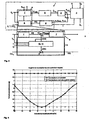
- einen Vergleich zweier Korrekturkurven vor und nach einer aktuellen Anpassung.
- Fig. 1
- typical Heizungsfahrkurven a heating control;
- Fig. 2
- a signal flow plan for on-demand heat supply according to a first embodiment of the present invention;
- Fig. 3
- a signal flow plan for on-demand heat supply according to a second embodiment of the present invention;
- Fig. 4
- a first correction curve according to the present invention;
- Fig. 5
- a second correction curve according to the present invention and
- Fig. 6
- a comparison of two correction curves before and after a current adjustment.
In
In dem in
Die Raumtemperaturregelungen 3 stellen durch Regelung beispielsweise der Hubpositionen von Stellventilen der Heizelemente die in den jeweiligen Räumen gewünschte Temperatur ein. Diese Einzelraumregelungen 3 berücksichtigen dabei beispielsweise die Außentemperatur ϑA und die als Wärmegewinne zu bezeichnenden solare Wärmeleistung Q̇ S und interne Wärmeleistung Q̇ i. Für die vorliegende Erfindung ist jedoch nicht ausschlaggebend, aufgrund welcher Eingangsgrößen die Raumtemperaturregelungen 3 die Temperatur in den zu beheizenden Räumen regeln. Daher ist die vorliegende Erfindung für jede Art von angeschlossenen Raumtemperaturregelungen 3 geeignet, die alternativ oder zusätzlich auch von anderen Eingangsgrößen abhängen können.The room temperature controls 3 adjust the desired temperature in the respective rooms by controlling, for example, the stroke positions of control valves of the heating elements. These individual room controls 3 take into account, for example, the outside temperature θ A and the heat output to be designated solar heat output Q̇ S and internal heat output Q̇ i . However, it is not decisive for the present invention, on the basis of which input variables, the room temperature controls 3, the temperature in the zu regulate heated rooms. Therefore, the present invention is suitable for any type of connected room temperature controls 3, which may alternatively or additionally depend on other input variables.
Jede Raumtemperaturregelung 3 übermittelt Informationen I zur Bestimmung des Wärmebedarfs an ein Modul zur Wärmebedarfs- oder Wärmeleistungsanalyse 4 weiter, welches daraus einen momentanen oder gemittelten Wärmebedarf DQ ermittelt. Hierzu können die Informationen 1, wie in der
Dieser für das Gebäude oder einen Heizkreis in einer bestimmten Situation ermittelte Wärmebedarf DQ wird einem Modul mit einer Schaltung 5 zur Vorgabe von Korrekturwerten zugeführt, die gemeinsam mit der Wärmeleistungsregelung 7 eine Steuerung 6 zur Vorgabe der Stellgröße UHZG bildet. Dabei werden von der Steuerung 6 weitere Eingabegrößen wie insbesondere der Wärmebedarf-Sollwert DQS, die aktuelle Vorlauftemperatur ϑHVL und/oder der aktuelle Massenstrom ṁ berücksichtigt.This calculated for the building or a heating circuit in a given situation heat demand DQ is supplied to a module with a
Das Zusammenwirken der den Kern der Erfindung ausmachenden Schaltung 5 zur Vorgabe von Korrekturwerten mit der Wärmeleistungsregelung 7 im Rahmen der Steuerung 6 wird in der Vergrößerung von
Aus dem von dem Modul 4 zur Wärmebedarfsanalyse ermittelten momentanen Wärmebedarf DQ und einem vorgegebenen Wärmebedarf-Sollwert DQS wird in einem Differenzmodul 9 eine Regelabweichung des Wärmebedarfs ΔDQ ermittelt, welche nachfolgend vereinfacht auch als Wärmebedarf bezeichnet wird. Diese Regelabweichung ΔDQ wird einem Korrekturmodul 11 zugeführt, welches daraus einen aktuellen Korrekturwert DXSAKT ermittelt. Dazu weist das Korrekturmodul 11 Regelungs- und Filterfunktionen auf, die geeignet parametriert sind. Insbesondere kann das Korrekturmodul also in Form einer herkömmlichen Regelung ausgebildet sein, die unter Verwendung gängiger Regelalgorithmen, beispielsweise aus der Regelungstechnik bekannte Filter- und Lernverfahren wie PT-1-Filter, Splines, oder auch künstlicher Intelligenz in Form neuronaler Netze, aus der aktuellen Regelabweichung ΔDQ des aktuellen Wärmebedarfs einen aktuellen Korrekturwert DXSAKT ermittelt.From the instantaneous heat demand DQ determined by the
Dieser aktuelle Korrekturwert DXSAKT wird allerdings nicht der Heizungsregelung 7 zugeführt und daher nicht unmittelbar zur Regelung bzw. Steuerung der Heizungsanlage 2 verwendet. Der Eingriff in die Heizungsregelung 7 erfolgt durch das Korrekturkurvenadaptionsmodul 10, welches primär einen Korrekturwert DXS aus einer Korrekturkurve in Abhängigkeit von der als externe Führungsgröße dienenden Außentemperatur ϑA ermittelt. Dieser Korrekturwert wird als Korrektursollgröße DXS ausgegeben und einem Addierer 12 zugeführt, der die Korrektursollgröße DXS zu einer aus einer stationären Heizkurve gemäß
Der Korrekturwert DXS des Korrekturkurvenadaptionsmoduls 10 ist also unabhängig von der aktuellen Regelabweichung ΔDQ des Wärmebedarfs.The correction value DXS of the correction
Um eine in dem Korrekturkurvenadaptionsmodul 10 gespeicherte (und für die Bestimmung des Korrekturwertes DXS herangezogene) Korrekturkurve erfindungsgemäß anzupassen, erfasst das Korrekturkurvenadaptionsmodul 10 sowohl den durch das Korrekturmodul 11 ausgegebenen aktuellen Korrekturwert DXSAKT als auch die jeweils aktuelle Außentemperatur ϑA,AKT und mittelt diese über einen vorgegebenen Zeitraum. Auf Basis der für diesen Zeitraum gemittelten Außentemperatur ϑA,AKT als Führungsgröße und eines mittleren Korrekturwert DXSAKT wird die Korrekturkurve dann korrigiert wird. Dies kann auch in dem Korrekturkurvenadaptionsmodul 10 unter Verwendung gängiger Regelalgorithmen, aus der Regelungstechnik bekannter Filter- und Lernverfahren wie PT-1-Filter, Splines, etc. oder auch künstlicher Intelligenz in Form neuronaler Netze erfolgen.In order to adapt a correction curve stored in the correction curve adaptation module 10 (and used for the determination of the correction value DXS), the correction
Diese korrigierte Korrekturkurve wird im Folgenden dann zur Ausgabe der Korrekturwerte DXS verwendet, welche gemeinsam mit der Sollgröße XS die korrigierte Sollgröße XSKORR bildet, aus der die Stellgröße UHZG für den Wärmeerzeuger 8 berechnet wird.This corrected correction curve is then subsequently used to output the correction values DXS, which together with the setpoint variable XS forms the corrected setpoint variable XS KORR , from which the manipulated variable U HZG for the
Die Besonderheit der Schaltung 5 zur Vorgabe von Korrekturwerten DXS liegt also darin, dass die Korrekturwerte DXS aus einer gespeicherten Korrekturkurve in Abhängigkeit von der als Führungsgröße dienenden Außentemperatur ϑA bestimmt werden. Hierbei handelt es sich streng genommen um eine Steuerung, da in dem System auftretende Regelabweichungen ΔDQ nicht direkt berücksichtigt werden. Diese finden lediglich bei der Anpassung der Korrekturkurve in dem Korrekturkurvenadaptionsmodul 10 Anwendung und können bei der zukünftigen Ansteuerung der Heizungsanlage 2 verwendet werden.The peculiarity of the
Dabei sind in dem Korrekturkurvenadaptionsmodul 10 mehrere Korrekturkurven in Abhängigkeit von der Tageszeit T und dem Tagestyp D gespeichert, die jeweils gesondert korrigiert werden. Dazu kann der vorbestimmte Zeitraum, nach dem eine Adaption der Korrekturkurve vorgenommen wird, mit den vorgesehen Tageszeitintervallen T der jeweiligen Tagestypen D zusammenfallen.In this case, a plurality of correction curves are stored in the correction
Eine Variante der Schaltung 5 zur Vorgabe von Korrekturwerten DXS ist in
Nachfolgend wird das in der Schaltung 5 zur Vorgabe von Korrekturwerten DXS vorgesehene Verfahren noch einmal im Detail beschrieben.Hereinafter, the method provided in the
Eingangswerte der Schaltung 5 zur Vorgabe von Korrekturwerten DXS, in der das erfindungsgemäße Verfahren implementiert ist und die insbesondere Bestandteil der erfindungsgemäßen Vorrichtung ist, sind zeitlich aktuelle bzw. zeitlich gemittelte Kenngrößen, aus denen sich der zeitlich aktuelle bzw. der zeitlich gemittelte Heizwärmebedarf des Gebäudes oder Heizkreises ermitteln lässt. Diese Eingangswerte können die Außentemperatur ϑA oder eine korrelierte Messgröße (wie etwa Widerstandswerte von Sensoren), die Tageszeit T, der Tagestyp D (bspw. Werktag, Feiertag), Profilzeiträume (bspw. Nacht, Vormittag, Nachmittag, Abend), Versorgungszustände von Heizflächen und deren Sollwerte, Versorgungszustände von Gebäuden, Gebäudeteilen oder Heizkreisen und deren Sollwerte, Heizkörperleistungen Q̇ HK und deren Sollwerte, Heizkörper-Nennleistungen im Normalarbeitspunkt Q̇ HK, Nenn, Heizkörper-Leistungen bei der aktuellen Vorlauftemperatur und dem Nennmassenstrom Q̇ HK, dm_Nenn, Heizkörper-Leistungen bei aktueller Vorlauftemperatur und bei vollständig geöffnetem Heizkörperventil Q̇ HK, Hub_100n und/oder Leistungsverhältnisse von Heizkörpern und deren Sollwerte ![]()
![]()
Ziel des Verfahrens ist es, Korrekturwerte DXS zur Korrektur der Vorlauftemperatur und/oder des Massenstroms einer zentralen Heizungsanlage 2 auszugeben. Diese werden einer oder mehreren, in der Schaltung 5 zur Vorgabe der Korrekturwerte gespeicherten Korrekturkurve(n) in Abhängigkeit der externen Führungsgröße (Außentemperatur oder deren Äquivalent) entnommen. Dabei sind abhängig von dem aktuellen Tagestyp (Werktag, Feiertag) und dem aktuellen Tageszeitabschnitt (Profil) verschiedene Korrekturkurven gespeichert, indem an bestimmten Stützstellen der externen Führungsgröße (Außentemperatur) Korrekturwerte gespeichert sind. Aus diesen wird inter- oder extrapolierend oder auch approximierend eine Korrekturstellgröße DXS berechnet und an den Heizungsregler übergeben bzw. von ihm bestimmt. Die resultierende, korrigierte Stellgröße UHZG wird aus dem Basissollwert XS der Wärmeleistungsregelung 7 und dem Korrekturwertes DXS sowie ggf. unter Berücksichtigung der aktuellen Istwerte der Vorlauftemperatur und/oder des Massenstroms in einem festgelegten Regelalgorithmus gebildet.The aim of the method is to output correction values DXS for correcting the flow temperature and / or the mass flow of a
Beispiele für verwendete Korrekturkurven sind in den
Die Korrekturkurven gemäß
Es ist gemäß der beschriebenen Ausführungsform jedoch vorgesehen, dass die Korrekturkurven in der Schaltung 5 selbsttätig ermittelt werden, wobei sie sich entsprechend dem Nutzerverhalten iterativ anpassen. Dazu ist vorgesehen, dass aktuelle oder zeitlich gemittelte Korrekturwerte zur Korrektur von Vorlauftemperatur und/oder Massenstrom der Heizungsanlage auf Grundlage der ermittelten Abweichung zwischen Soll- und Ist-Wert der den Wärmebedarf anzeigenden Kenngröße (Regelabweichung ΔDQ) errechnet werden. Die Kenngrößen können, wie bereits erläutert, Versorgungszustände von Heizflächen, Versorgungszustände von Gebäuden, Gebäudeteilen oder Heizkreisen und deren Sollwerte, Heizkörperleistungen Q̇ HK und deren Sollwerte, Heizkörper-Nennleistungen im Normalarbeitspunkt Q̇ HK, Nenn, Heizkörper-Leistungen bei der aktuellen Vorlauftemperatur und dem Nennmassenstrom Q̇ HK, dm_Nenn, Heizkörper-Leistungen bei aktueller Vorlauftemperatur und bei vollständig geöffnetem Heizkörperventil Q̇ HK, Hub_100n und/oder Leistungsverhältnisse von Heizkörpern und deren Sollwerte ![]()
![]()
Die aktuellen Korrekturwerte DXSAKT zur Korrektur der Vorlauftemperatur und/oder des Massenstroms der zentralen Heizungsanlage 2 werden nach an sich bekannten Verfahren der Regelungstechnik so bestimmt, dass die Regelabweichungen der Kenngröße minimiert werden bzw. gegen Null führen. Vorteilhaft im Sinne einer hohen Systemstabilität ist es dabei, wenn die Anpassung der Korrekturkurve innerhalb einer vorgegebenen Zeitperiode, beispielsweise einer täglichen Korrekturwertadaption, auf einen maximalen parametrierbaren Bereich begrenzt wird, so dass eine Adaption insbesondere nur um einen maximalen Wert geändert werden kann.The current correction values DXS AKT for correcting the flow temperature and / or the mass flow of the
Die Regelabweichungen der Kenngrößen und der daraus resultierenden aktuellen Korrekturgrößen zur Korrektur von Vorlauftemperatur und/oder Massenstrom der zentralen Heizungsanlage 2 werden während der auch als Lernphasen bezeichneten, vorgegebenen Zeitperioden gemittelt bzw. gefiltert. Ebenso werden während dieser Lernphasen die Außentemperatur ϑA oder eine mit der Außentemperatur korrelierte Größe gemittelt bzw. gefiltert. Nach Abschluss jeder Lernphase bspw. der Zeitdauer eines Tagesprofilzeitraums, wird ein Satz von Korrekturstützwerten DXSNode(i) in festen oder variablen Stützstellen (i) der Außentemperatur ϑA oder einer mit der Außentemperatur korrelierten Größe (zum Beispiel Widerstandswerte eines Außentemperatursensors) mit Hilfe der gemittelten Werte (Korrekturwerte und Außentemperatur) trainiert bzw. angepasst. Im Ergebnis entstehen zeitvariante, adaptive Korrekturkurven DXSNode (i), die sich selbsttätig insbesondere auch an ein sich änderndes Nutzerverhalten anpassen.The control deviations of the parameters and the resulting actual correction quantities for the correction of flow temperature and / or mass flow of the
Das Lernen der Korrekturwerte in den Stützstellen erfolgt iterativ unter Berücksichtigung von Vergangenheits- und Momentanwerten. Hierfür können bekannte Filter- und Lernverfahren der Regelungstechnik oder auch der künstlichen Intelligenz verwendet werden: ![]()
- DXSNode(i)
- Korrekturwert in der Stützstelle i;
- DXSAKT
- gemittelte bzw. aktuelle Korrekturgröße der letzten Lernphase;
- ϑ A, AKT
- Außentemperatur (oder Äquivalent)der letzten Lernphase.
- DXS node (i)
- Correction value in the support point i;
- DXS ACT
- averaged or actual correction value of the last learning phase;
- θ A, AKT
- Outside temperature (or equivalent) of the last learning phase.
Dieses Vorgehen ist den nebeneinander dargestellten Korrekturkurven in
Vorteilhaft ist auch eine gewichtete Verteilung des Korrekturwertes DXSAKT aus der aktuellen Lernphase auf die Korrekturstützwerte DXSNode(i) auf Basis der Außentemperatur oder des Außentemperaturäquivalents ϑA, AKT entsprechend der folgenden Formel: ![]()
wobei ![]()
![]()
- ϑA_Node (i)
- Außentemperatur oder Äquivalent in der Stützstelle i und
- K
- Verteilungskonstante.
in which
- θ A_Node ( i )
- Outside temperature or equivalent in the support point i and
- K
- Distribution constant.
Idealerweise sind die Lernphase bzw. die vorgegebenen Zeitperioden Tageszeitabschnitten zugeordnet, denen ein signifikant unterschiedliches Nutzerverhalten entspricht. Beispiele hierfür sind die Tagesabschnitte Nacht, Vormittag, Nachmittag und Abend. Die Korrekturkurven können als Wertepaare (Korrekturwert DXSNode(i), Außentemperatur ϑA(i)) im Speicher der Schaltung 5 hinterlegt sein. Die Korrekturkurven sind dem Tagestyp (Werktag, Feiertag) und den Tageszeitabschnitten (Nacht, Vormittag, Nachmittag, Abend) zugeordnet, während derer sie trainiert wurden. Sie widerspiegeln das tagestyp- und tageszeitabhängige sowie außentemperaturabhängige Nutzerverhalten und den Heizungsanlagenbetrieb in einem Gebäude.Ideally, the learning phase or the predefined time periods are assigned to time segments which correspond to a significantly different user behavior. Examples of this are the daily sections night, morning, Afternoon and evening. The correction curves can be stored as value pairs (correction value DXS Node (i), outside temperature θ A (i)) in the memory of the
Der Mittelwert der gelernten Korrekturkurven über alle Stützstellen zeigt die mittlere Absenkung des Massenstroms oder der Vorlauftemperatur gegenüber den Basis-Sollwerten, die sich aus den Grundeinstellungen der Wärmeleistungsregelung 7 ergeben. Die aktuellen Korrekturwerte zeigen die momentane Absenkung des Massenstroms oder der Vorlauftemperatur gegenüber den Basis-Sollwerten. Sowohl die mittleren als auch die aktuellen Korrekturwerte können zur Erfolgsbewertung des Verfahrens gespeichert und genutzt werden. So entspricht bspw. eine Absenkung der Vorlauftemperatur um 1 KelVin in Deutschland ca. 2% Einsparung an Heizenergie.The mean value of the learned correction curves over all interpolation points shows the mean reduction of the mass flow or the flow temperature compared to the basic setpoint values which result from the basic settings of the heat output control 7. The current correction values show the instantaneous reduction of the mass flow or the flow temperature compared to the basic setpoints. Both the mean and the current correction values can be stored and used to evaluate the success of the procedure. For example, a reduction in the flow temperature by 1 Kelvin in Germany corresponds to a saving of approx. 2% in heating energy.
Die adaptiven Korrekturkurven sind eine Eigenschaft des Systems 'Gebäude/Nutzer' und können auch nach einer Abschaltung der Korrekturlogik bzw. Schaltung 5, die diese Korrekturkurven anpasst und trainiert, zur Schätzung eines optimalen Sollwerts für die Vorlauftemperatur und/oder den Massenstrom verwendet werden.The adaptive correction curves are a property of the 'building / user' system and may be used to estimate an optimal set point for the flow temperature and / or mass flow even after a shutdown of the correction logic or
Indem die vorliegende Erfindung Korrekturkurven in kleinen Schritten tagweise und profilbasiert erlernt (trainiert), werden Instabilitäten im System für die bedarfsgeführte Heizenergiebereitstellung vermieden. Zudem werden geringe Anforderungen an die Datenübertragungsperformance von Kommunikationsinfrastrukturen innerhalb des Gebäudes zur Übertragung der Kennwerte und Stellgrößen in Folge tagweiser und profilbasierter Lernphasen gestellt, da bei Ausfall der Kommunikation lediglich ein Trainingsschritt entfällt.By learning (training) correction curves in small increments per day and profile-based, instabilities in the on-demand heating energy delivery system are avoided. In addition, low requirements are placed on the data transmission performance of communication infrastructures within the building for transmitting the characteristic values and manipulated variables as a result of day-by-day and profile-based learning phases, since only one training step is required if communication fails.
Das erfindungsgemäß vorgeschlagene System kann flexibel in eine Vielzahl bestehender Heizungsanlagen integriert werden, da das System aufgrund der selbsttätigen, iterativen Adaption ohne die Notwendigkeit von Vorgaben an die verschiedensten Heizungssysteme angepasst werden kann.The inventively proposed system can be flexibly integrated into a variety of existing heating systems, since the system can be adapted due to the automatic, iterative adaptation without the need for specifications to a variety of heating systems.
Die erlernten Korrekturkurven veranschaulichen dem technischen Personal der Gebäude- und Haustechnik die Abweichung der eingestellten Basis-Sollwerte vom energetischen Optimum für die Vorlauftemperatur und/oder für den Heizungsmassenstrom. Aus den erlernten Korrekturkurven kann die erzielte, aktuelle und mittlere Energieeinsparung gegenüber den nicht korrigierten Basis-Sollwerten für den Heizungsmassenstrom und/oder die Vorlauftemperatur errechnet werden.The learned correction curves illustrate the technical personnel of the building and building services the deviation of the set base setpoints from the energetic optimum for the flow temperature and / or for the mass flow of heating. From the correction curves learned, the achieved, current and average energy savings compared to the uncorrected base setpoint values for the heating mass flow and / or the flow temperature can be calculated.
- 11
- Heizungssteuerung bzw. -regelungHeating control or regulation
- 22
- Heizungsanlageheating system
- 33
- RaumtemperaturregelungRoom temperature control
- 44
- Modul zur Wärmebedarfs- oder WärmeleistungsanalyseModule for heat demand or heat output analysis
- 55
- Schaltung zur Vorgabe von KorrekturwertenCircuit for specifying correction values
- 66
- Steuerungcontrol
- 77
- WärmeleistungsregelungThermal output control
- 88th
- Wärmeerzeuger oder WärmeübertragerHeat generator or heat exchanger
- 99
- Differenzmoduldifference module
- 1010
- KorrekturkurvenadaptionsmodulCorrection curve adaptation module
- 1111
- Korrekturmodulcorrection module
- 1212
- Additionsmoduladdition module
- DD
- Tagestypday type
- DQDQ
- Wärmebedarfheat demand
- DQS DQ S
- Wärmebedarf-SollwertHeat demand setpoint
- DXSDXS
- Korrekturwert, KorrekturstollgrößeCorrection value, correction target size
- ΔDQ Δ DQ
- Regelabweichung des WärmebedarfsControl deviation of the heat demand
- II
- Informationen zur Bestimmung des WärmebedarfsInformation for determining the heat requirement
- ṁm '
- Massenstrommass flow
- Q̇TH Q̇ TH
- HeizungswärmeleistungHeating heat output
- TT
- Tageszeitdaytime
- ϑA θ A
- Außentemperaturoutside temperature
- ϑHVL θ HVL
- Vorlauftemperaturflow temperature
- ϑHRL θ HRL
- RücklauftemperaturReturn temperature
- UHZG U HZG
- Stellgrößemanipulated variable
- XSXS
- Sollgrößeintended size
Claims (12)
- Method for demand-driven heat provision in a heating system (2), to which a specified thermal power (Q˙TH) is provided in accordance with an external reference variable (ϑA) wherein the thermal power (Q˙ TH ) provided additionally depends on the heat requirement (DQ) of the heating system (2), by the dependence on the external reference variable (ϑA) being such as to take into account correction values (DXS) that are determined from a correction curve in accordance with the external reference variable (ϑA), which is a non-stationary, adaptive correction curve that is adapted after specified time periods,
characterized in that
the correction curve is adapted by the fact that over a pre-specified time period, the current heat requirement (DQ) of the heating system (2) is used as a control variable (ΔDQ) of a control system, and the control system outputs a current correction value (DXSAKT) as a correction factor, wherein the correction curve is adapted by averaging the current correction values (DXSAKT) during the specified time period. - The method according to Claim 1,
characterized in that
an averaging of the external reference variable (ϑA) is carried out in order to adapt the correction curve. - The method according to any one of Claims 1 or 2,
characterized in that
the adaptation of the correction curve is weighted with the external reference variable (ϑA). - The method according to any one of the preceding claims,
characterized in that
the adaptation of the correction curve is restricted to a specified range of values. - The method according to any one of the preceding claims,
characterized in that
a plurality of correction curves are provided for different time periods. - The method according to any one of the preceding claims,
characterized in that
the correction curve is specified by the setting of correction values (DXSNode(i)) at reference points (i) for values of the external reference variable (ϑA(i)). - The method according to Claim 6,
characterized in that
for values of the external reference variable (ϑA(i)) which do not lie at the reference points (i), an interpolation or extrapolation of the correction values is performed. - The method according to the preceding claims,
characterized in that
the external reference variable is either the external temperature (ϑA) or a variable that is dependent on the external temperature. - The method according to any one of the preceding claims,
characterized in that
the correction value (DXS) is a change in the supply temperature (ϑHVL) and/or in the mass flow (m) of the heating system. - Device for demand-driven heat provision in a heating system (2), with a logic circuit (5) for specifying correction values (DXS) which take into account the heat requirement (DQ) of the heating system (2), wherein the logic circuit (5) comprises a correction curve adaptation module (10) with a memory for storing one or a plurality of correction curve (s), an input for entering at least one external reference variable (ϑA) and an output for outputting a correction value (DXS), wherein a correction module (11) with an input for entering a current heat requirement (ΔDQ) of the heating system (2) is provided, which is designed to determine a current correction value (DXSAKT) from the current heat requirement (ΔDQ), and that the correction curve adaptation module (10) is designed to determine the correction value (DXS) from a correction curve in accordance with the external reference variable (ϑA) and to adapt the correction curve,
characterized in that
the correction module (11) comprises a control system for determining the current correction values (DXSAKT) from the current heat requirement (ΔDQ) of the heating system (2), and the device for carrying out the method is designed according to any one of Claims 1 to 9. - The device according to Claim 10,
characterised in that
the correction curve adaptation module (10) is designed for averaging the reference variable (ϑA) and the current correction value (DXSAKT) over a specified time period. - The device according to any one of Claims 10 or 11,
characterized in that
the logic circuit (5) and/or the heating power control system (7) are integrated into a boiler control system.
Priority Applications (1)
| Application Number | Priority Date | Filing Date | Title |
|---|---|---|---|
| PL06024568T PL1837729T3 (en) | 2006-03-20 | 2006-11-28 | Method and device for demand-driven heat provision in a heating system |
Applications Claiming Priority (1)
| Application Number | Priority Date | Filing Date | Title |
|---|---|---|---|
| DE102006013098A DE102006013098C5 (en) | 2006-03-20 | 2006-03-20 | Method and device for on-demand heat supply in a heating system |
Publications (3)
| Publication Number | Publication Date |
|---|---|
| EP1837729A2 EP1837729A2 (en) | 2007-09-26 |
| EP1837729A3 EP1837729A3 (en) | 2013-05-29 |
| EP1837729B1 true EP1837729B1 (en) | 2015-05-06 |
Family
ID=37776075
Family Applications (1)
| Application Number | Title | Priority Date | Filing Date |
|---|---|---|---|
| EP20060024568 Active EP1837729B1 (en) | 2006-03-20 | 2006-11-28 | Method and device for demand-driven heat provision in a heating system |
Country Status (5)
| Country | Link |
|---|---|
| EP (1) | EP1837729B1 (en) |
| DE (1) | DE102006013098C5 (en) |
| DK (1) | DK1837729T3 (en) |
| HU (1) | HUE025293T2 (en) |
| PL (1) | PL1837729T3 (en) |
Families Citing this family (7)
| Publication number | Priority date | Publication date | Assignee | Title |
|---|---|---|---|---|
| DE102007029631A1 (en) | 2007-06-26 | 2009-01-02 | Techem Energy Services Gmbh | Method and device for adjusting the heating power reserve |
| DE102008054043A1 (en) * | 2008-10-30 | 2010-05-12 | Techem Energy Services Gmbh | Method and device for heat demand-guided adaptation of the flow temperature of a heating system |
| DE102010006110A1 (en) | 2010-01-29 | 2011-08-04 | IAIB e.V., 23966 | Method for regulating heater of building system, involves generating cyclic heating output with heater, where cyclic heating output comprises heating phase and heating break relative to time period |
| EP2369245B1 (en) | 2010-03-16 | 2012-09-26 | Rehau AG & Co | Method for altering a preheat temperature target value of a heating curve for a heating assembly |
| DE102010053211B4 (en) | 2010-12-03 | 2019-05-09 | Thermia Ab | Method for operating and adjusting the heat curve of a heating system |
| SE539644C2 (en) * | 2015-12-28 | 2017-10-24 | Nordomatic Ab | Method and system for regulating indoor temperature |
| CN108241392A (en) * | 2016-12-26 | 2018-07-03 | 航天信息股份有限公司 | Temprature control method and system |
Family Cites Families (8)
| Publication number | Priority date | Publication date | Assignee | Title |
|---|---|---|---|---|
| DE3537104A1 (en) * | 1984-11-01 | 1986-05-07 | Vaillant Joh Gmbh & Co | Method for controlling the temperature of a central heating system |
| DE3620929A1 (en) * | 1986-06-23 | 1988-01-07 | Centra Buerkle Gmbh & Co | Method and device for controlling at least one heating installation |
| DE4009773C2 (en) * | 1990-03-27 | 1995-10-19 | Buderus Heiztechnik Gmbh | Process for changing the characteristic of a regulator for central heating boilers |
| ATE150189T1 (en) * | 1992-09-28 | 1997-03-15 | Landis & Gyr Tech Innovat | METHOD FOR ADJUSTING THE HEATING CHARACTERISTICS OF A HEATING CIRCUIT CONTROLLER |
| DE4312808A1 (en) * | 1993-04-20 | 1994-10-27 | Stiebel Eltron Gmbh & Co Kg | Method and apparatus for controlling a space-heating installation |
| AU2002361140A1 (en) * | 2001-12-19 | 2003-06-30 | Techem Development Gmbh | Method and device for adapting the thermal output in heating installations |
| DE102004020607B3 (en) * | 2004-04-27 | 2005-10-27 | Bbt Thermotechnik Gmbh | Method for controlling a heating system |
| DE102005012597A1 (en) * | 2004-10-07 | 2006-04-27 | Techem Energy Services Gmbh & Co. Kg | Method for determining a heating surface supply state and supply state regulation |
-
2006
- 2006-03-20 DE DE102006013098A patent/DE102006013098C5/en not_active Expired - Fee Related
- 2006-11-28 EP EP20060024568 patent/EP1837729B1/en active Active
- 2006-11-28 DK DK06024568.5T patent/DK1837729T3/en active
- 2006-11-28 HU HUE06024568A patent/HUE025293T2/en unknown
- 2006-11-28 PL PL06024568T patent/PL1837729T3/en unknown
Also Published As
| Publication number | Publication date |
|---|---|
| PL1837729T3 (en) | 2015-12-31 |
| DK1837729T3 (en) | 2015-08-03 |
| DE102006013098B3 (en) | 2007-03-22 |
| DE102006013098C5 (en) | 2010-08-19 |
| HUE025293T2 (en) | 2016-02-29 |
| EP1837729A3 (en) | 2013-05-29 |
| EP1837729A2 (en) | 2007-09-26 |
Similar Documents
| Publication | Publication Date | Title |
|---|---|---|
| EP1837729B1 (en) | Method and device for demand-driven heat provision in a heating system | |
| EP3593055B1 (en) | Method for operating a heating installation | |
| EP1645928B1 (en) | Method of determining the supply state of a heating surface and supply state regulator | |
| EP1456727B2 (en) | Method and device for adapting the thermal output in heating installations | |
| EP0729086B1 (en) | Method and device for controlling a low temperatue heating system | |
| EP0208256A2 (en) | Space temperature regulation device | |
| DE102008057730A1 (en) | Method for operating a system for transporting thermal energy over a liquid medium | |
| DE202012012915U1 (en) | Heating and / or cooling system | |
| EP0736826B1 (en) | Temperature responsive power control for an electric pump unit | |
| EP0594886B1 (en) | Method and controlling a heating system and device for carrying out the method | |
| DE19507247A1 (en) | Method and device for hydraulically optimized regulation of the flow temperature | |
| EP0308806B1 (en) | Selfadaptive control-method for temperature regulation of at least one space of a building | |
| CH664622A5 (en) | METHOD AND DEVICE FOR OPTIMIZING THE HEATING CURVE OF A HEATING SYSTEM. | |
| EP3874338B1 (en) | Method for operating a valve, related electronic control unit and valve drive | |
| DE102008040436A9 (en) | Method for determining a set flow temperature for controlling a hot water heating of a building | |
| EP2420748A2 (en) | Method and system for hydraulic balancing in a heating system | |
| WO2003023288A1 (en) | Central heating installation | |
| WO2020165037A1 (en) | Method for controlling a circulation pump | |
| EP2369245B1 (en) | Method for altering a preheat temperature target value of a heating curve for a heating assembly | |
| WO2022023006A1 (en) | Method for controlling a circulation pump, in particular a heating pump | |
| DE19600694A1 (en) | Room air-conditioning, heating control system | |
| EP3739267A1 (en) | Method and control unit for controlling a heating circuit | |
| DE10114822A1 (en) | Regulating or controlling energy supplied to heating bodies in heating system, involves limiting difference between return and forward flow temperatures by increasing volumetric flow | |
| EP0384959B1 (en) | Regulator for a non-modulating burner | |
| EP3350515B1 (en) | Method and device for regulating a temperature of a fluid carrier medium |
Legal Events
| Date | Code | Title | Description |
|---|---|---|---|
| PUAI | Public reference made under article 153(3) epc to a published international application that has entered the european phase |
Free format text: ORIGINAL CODE: 0009012 |
|
| AK | Designated contracting states |
Kind code of ref document: A2 Designated state(s): AT BE BG CH CY CZ DE DK EE ES FI FR GB GR HU IE IS IT LI LT LU LV MC NL PL PT RO SE SI SK TR |
|
| AX | Request for extension of the european patent |
Extension state: AL BA HR MK YU |
|
| PUAL | Search report despatched |
Free format text: ORIGINAL CODE: 0009013 |
|
| AK | Designated contracting states |
Kind code of ref document: A3 Designated state(s): AT BE BG CH CY CZ DE DK EE ES FI FR GB GR HU IE IS IT LI LT LU LV MC NL PL PT RO SE SI SK TR |
|
| AX | Request for extension of the european patent |
Extension state: AL BA HR MK RS |
|
| RIC1 | Information provided on ipc code assigned before grant |
Ipc: G05D 23/19 20060101AFI20130419BHEP |
|
| 17P | Request for examination filed |
Effective date: 20131128 |
|
| RBV | Designated contracting states (corrected) |
Designated state(s): AT BE BG CH CY CZ DE DK EE ES FI FR GB GR HU IE IS IT LI LT LU LV MC NL PL PT RO SE SI SK TR |
|
| AKX | Designation fees paid |
Designated state(s): AT BE BG CH CY CZ DE DK EE ES FI FR GB GR HU IE IS IT LI LT LU LV MC NL PL PT RO SE SI SK TR |
|
| GRAP | Despatch of communication of intention to grant a patent |
Free format text: ORIGINAL CODE: EPIDOSNIGR1 |
|
| INTG | Intention to grant announced |
Effective date: 20150206 |
|
| GRAS | Grant fee paid |
Free format text: ORIGINAL CODE: EPIDOSNIGR3 |
|
| GRAA | (expected) grant |
Free format text: ORIGINAL CODE: 0009210 |
|
| AK | Designated contracting states |
Kind code of ref document: B1 Designated state(s): AT BE BG CH CY CZ DE DK EE ES FI FR GB GR HU IE IS IT LI LT LU LV MC NL PL PT RO SE SI SK TR |
|
| REG | Reference to a national code |
Ref country code: GB Ref legal event code: FG4D Free format text: NOT ENGLISH |
|
| REG | Reference to a national code |
Ref country code: CH Ref legal event code: EP |
|
| REG | Reference to a national code |
Ref country code: IE Ref legal event code: FG4D Free format text: LANGUAGE OF EP DOCUMENT: GERMAN |
|
| REG | Reference to a national code |
Ref country code: DE Ref legal event code: R096 Ref document number: 502006014317 Country of ref document: DE Effective date: 20150611 |
|
| REG | Reference to a national code |
Ref country code: AT Ref legal event code: REF Ref document number: 726131 Country of ref document: AT Kind code of ref document: T Effective date: 20150615 |
|
| REG | Reference to a national code |
Ref country code: CH Ref legal event code: NV Representative=s name: BOHEST AG, CH |
|
| REG | Reference to a national code |
Ref country code: DK Ref legal event code: T3 Effective date: 20150730 |
|
| REG | Reference to a national code |
Ref country code: NL Ref legal event code: T3 |
|
| REG | Reference to a national code |
Ref country code: LT Ref legal event code: MG4D |
|
| PG25 | Lapsed in a contracting state [announced via postgrant information from national office to epo] |
Ref country code: FI Free format text: LAPSE BECAUSE OF FAILURE TO SUBMIT A TRANSLATION OF THE DESCRIPTION OR TO PAY THE FEE WITHIN THE PRESCRIBED TIME-LIMIT Effective date: 20150506 Ref country code: ES Free format text: LAPSE BECAUSE OF FAILURE TO SUBMIT A TRANSLATION OF THE DESCRIPTION OR TO PAY THE FEE WITHIN THE PRESCRIBED TIME-LIMIT Effective date: 20150506 Ref country code: PT Free format text: LAPSE BECAUSE OF FAILURE TO SUBMIT A TRANSLATION OF THE DESCRIPTION OR TO PAY THE FEE WITHIN THE PRESCRIBED TIME-LIMIT Effective date: 20150907 Ref country code: LT Free format text: LAPSE BECAUSE OF FAILURE TO SUBMIT A TRANSLATION OF THE DESCRIPTION OR TO PAY THE FEE WITHIN THE PRESCRIBED TIME-LIMIT Effective date: 20150506 |
|
| PG25 | Lapsed in a contracting state [announced via postgrant information from national office to epo] |
Ref country code: BG Free format text: LAPSE BECAUSE OF FAILURE TO SUBMIT A TRANSLATION OF THE DESCRIPTION OR TO PAY THE FEE WITHIN THE PRESCRIBED TIME-LIMIT Effective date: 20150806 Ref country code: GR Free format text: LAPSE BECAUSE OF FAILURE TO SUBMIT A TRANSLATION OF THE DESCRIPTION OR TO PAY THE FEE WITHIN THE PRESCRIBED TIME-LIMIT Effective date: 20150807 Ref country code: IS Free format text: LAPSE BECAUSE OF FAILURE TO SUBMIT A TRANSLATION OF THE DESCRIPTION OR TO PAY THE FEE WITHIN THE PRESCRIBED TIME-LIMIT Effective date: 20150906 Ref country code: LV Free format text: LAPSE BECAUSE OF FAILURE TO SUBMIT A TRANSLATION OF THE DESCRIPTION OR TO PAY THE FEE WITHIN THE PRESCRIBED TIME-LIMIT Effective date: 20150506 |
|
| REG | Reference to a national code |
Ref country code: PL Ref legal event code: T3 |
|
| PG25 | Lapsed in a contracting state [announced via postgrant information from national office to epo] |
Ref country code: EE Free format text: LAPSE BECAUSE OF FAILURE TO SUBMIT A TRANSLATION OF THE DESCRIPTION OR TO PAY THE FEE WITHIN THE PRESCRIBED TIME-LIMIT Effective date: 20150506 |
|
| PGFP | Annual fee paid to national office [announced via postgrant information from national office to epo] |
Ref country code: CH Payment date: 20151123 Year of fee payment: 10 |
|
| REG | Reference to a national code |
Ref country code: DE Ref legal event code: R097 Ref document number: 502006014317 Country of ref document: DE |
|
| PG25 | Lapsed in a contracting state [announced via postgrant information from national office to epo] |
Ref country code: SK Free format text: LAPSE BECAUSE OF FAILURE TO SUBMIT A TRANSLATION OF THE DESCRIPTION OR TO PAY THE FEE WITHIN THE PRESCRIBED TIME-LIMIT Effective date: 20150506 Ref country code: RO Free format text: LAPSE BECAUSE OF NON-PAYMENT OF DUE FEES Effective date: 20150506 |
|
| PGFP | Annual fee paid to national office [announced via postgrant information from national office to epo] |
Ref country code: CZ Payment date: 20151118 Year of fee payment: 10 |
|
| REG | Reference to a national code |
Ref country code: HU Ref legal event code: AG4A Ref document number: E025293 Country of ref document: HU |
|
| PLBE | No opposition filed within time limit |
Free format text: ORIGINAL CODE: 0009261 |
|
| STAA | Information on the status of an ep patent application or granted ep patent |
Free format text: STATUS: NO OPPOSITION FILED WITHIN TIME LIMIT |
|
| 26N | No opposition filed |
Effective date: 20160209 |
|
| PG25 | Lapsed in a contracting state [announced via postgrant information from national office to epo] |
Ref country code: IT Free format text: LAPSE BECAUSE OF FAILURE TO SUBMIT A TRANSLATION OF THE DESCRIPTION OR TO PAY THE FEE WITHIN THE PRESCRIBED TIME-LIMIT Effective date: 20150506 |
|
| PG25 | Lapsed in a contracting state [announced via postgrant information from national office to epo] |
Ref country code: SI Free format text: LAPSE BECAUSE OF FAILURE TO SUBMIT A TRANSLATION OF THE DESCRIPTION OR TO PAY THE FEE WITHIN THE PRESCRIBED TIME-LIMIT Effective date: 20150506 |
|
| PG25 | Lapsed in a contracting state [announced via postgrant information from national office to epo] |
Ref country code: LU Free format text: LAPSE BECAUSE OF FAILURE TO SUBMIT A TRANSLATION OF THE DESCRIPTION OR TO PAY THE FEE WITHIN THE PRESCRIBED TIME-LIMIT Effective date: 20151128 Ref country code: MC Free format text: LAPSE BECAUSE OF FAILURE TO SUBMIT A TRANSLATION OF THE DESCRIPTION OR TO PAY THE FEE WITHIN THE PRESCRIBED TIME-LIMIT Effective date: 20150506 |
|
| GBPC | Gb: european patent ceased through non-payment of renewal fee |
Effective date: 20151128 |
|
| REG | Reference to a national code |
Ref country code: IE Ref legal event code: MM4A |
|
| REG | Reference to a national code |
Ref country code: FR Ref legal event code: ST Effective date: 20160729 |
|
| PG25 | Lapsed in a contracting state [announced via postgrant information from national office to epo] |
Ref country code: GB Free format text: LAPSE BECAUSE OF NON-PAYMENT OF DUE FEES Effective date: 20151128 Ref country code: IE Free format text: LAPSE BECAUSE OF NON-PAYMENT OF DUE FEES Effective date: 20151128 |
|
| PG25 | Lapsed in a contracting state [announced via postgrant information from national office to epo] |
Ref country code: FR Free format text: LAPSE BECAUSE OF NON-PAYMENT OF DUE FEES Effective date: 20151130 |
|
| PGFP | Annual fee paid to national office [announced via postgrant information from national office to epo] |
Ref country code: DK Payment date: 20161124 Year of fee payment: 11 Ref country code: NL Payment date: 20161124 Year of fee payment: 11 Ref country code: HU Payment date: 20161118 Year of fee payment: 11 |
|
| PG25 | Lapsed in a contracting state [announced via postgrant information from national office to epo] |
Ref country code: SE Free format text: LAPSE BECAUSE OF FAILURE TO SUBMIT A TRANSLATION OF THE DESCRIPTION OR TO PAY THE FEE WITHIN THE PRESCRIBED TIME-LIMIT Effective date: 20150506 Ref country code: CY Free format text: LAPSE BECAUSE OF FAILURE TO SUBMIT A TRANSLATION OF THE DESCRIPTION OR TO PAY THE FEE WITHIN THE PRESCRIBED TIME-LIMIT Effective date: 20150506 |
|
| REG | Reference to a national code |
Ref country code: CH Ref legal event code: PL |
|
| PG25 | Lapsed in a contracting state [announced via postgrant information from national office to epo] |
Ref country code: LI Free format text: LAPSE BECAUSE OF NON-PAYMENT OF DUE FEES Effective date: 20161130 Ref country code: CZ Free format text: LAPSE BECAUSE OF NON-PAYMENT OF DUE FEES Effective date: 20161128 Ref country code: CH Free format text: LAPSE BECAUSE OF NON-PAYMENT OF DUE FEES Effective date: 20161130 Ref country code: BE Free format text: LAPSE BECAUSE OF NON-PAYMENT OF DUE FEES Effective date: 20151130 |
|
| PG25 | Lapsed in a contracting state [announced via postgrant information from national office to epo] |
Ref country code: TR Free format text: LAPSE BECAUSE OF FAILURE TO SUBMIT A TRANSLATION OF THE DESCRIPTION OR TO PAY THE FEE WITHIN THE PRESCRIBED TIME-LIMIT Effective date: 20150506 |
|
| PGFP | Annual fee paid to national office [announced via postgrant information from national office to epo] |
Ref country code: AT Payment date: 20171117 Year of fee payment: 12 Ref country code: PL Payment date: 20171116 Year of fee payment: 12 |
|
| REG | Reference to a national code |
Ref country code: DK Ref legal event code: EBP Effective date: 20171130 |
|
| REG | Reference to a national code |
Ref country code: NL Ref legal event code: MM Effective date: 20171201 |
|
| PG25 | Lapsed in a contracting state [announced via postgrant information from national office to epo] |
Ref country code: HU Free format text: LAPSE BECAUSE OF NON-PAYMENT OF DUE FEES Effective date: 20171129 |
|
| PG25 | Lapsed in a contracting state [announced via postgrant information from national office to epo] |
Ref country code: NL Free format text: LAPSE BECAUSE OF NON-PAYMENT OF DUE FEES Effective date: 20171201 |
|
| PG25 | Lapsed in a contracting state [announced via postgrant information from national office to epo] |
Ref country code: DK Free format text: LAPSE BECAUSE OF NON-PAYMENT OF DUE FEES Effective date: 20171130 |
|
| REG | Reference to a national code |
Ref country code: AT Ref legal event code: MM01 Ref document number: 726131 Country of ref document: AT Kind code of ref document: T Effective date: 20181128 |
|
| PG25 | Lapsed in a contracting state [announced via postgrant information from national office to epo] |
Ref country code: AT Free format text: LAPSE BECAUSE OF NON-PAYMENT OF DUE FEES Effective date: 20181128 |
|
| PG25 | Lapsed in a contracting state [announced via postgrant information from national office to epo] |
Ref country code: PL Free format text: LAPSE BECAUSE OF NON-PAYMENT OF DUE FEES Effective date: 20181128 |
|
| P01 | Opt-out of the competence of the unified patent court (upc) registered |
Effective date: 20230527 |
|
| PGFP | Annual fee paid to national office [announced via postgrant information from national office to epo] |
Ref country code: DE Payment date: 20231120 Year of fee payment: 18 |