EP1837649A2 - Procédé et dispositif destinés à la mesure de la densité d'un milieu gazeux et/ou de la vitesse du son dans un milieu gazeux. - Google Patents
Procédé et dispositif destinés à la mesure de la densité d'un milieu gazeux et/ou de la vitesse du son dans un milieu gazeux. Download PDFInfo
- Publication number
- EP1837649A2 EP1837649A2 EP07005104A EP07005104A EP1837649A2 EP 1837649 A2 EP1837649 A2 EP 1837649A2 EP 07005104 A EP07005104 A EP 07005104A EP 07005104 A EP07005104 A EP 07005104A EP 1837649 A2 EP1837649 A2 EP 1837649A2
- Authority
- EP
- European Patent Office
- Prior art keywords
- sound transducer
- gaseous medium
- transducer
- chambers
- sound
- Prior art date
- Legal status (The legal status is an assumption and is not a legal conclusion. Google has not performed a legal analysis and makes no representation as to the accuracy of the status listed.)
- Granted
Links
Images


Classifications
-
- G—PHYSICS
- G01—MEASURING; TESTING
- G01N—INVESTIGATING OR ANALYSING MATERIALS BY DETERMINING THEIR CHEMICAL OR PHYSICAL PROPERTIES
- G01N29/00—Investigating or analysing materials by the use of ultrasonic, sonic or infrasonic waves; Visualisation of the interior of objects by transmitting ultrasonic or sonic waves through the object
- G01N29/02—Analysing fluids
- G01N29/036—Analysing fluids by measuring frequency or resonance of acoustic waves
-
- G—PHYSICS
- G01—MEASURING; TESTING
- G01N—INVESTIGATING OR ANALYSING MATERIALS BY DETERMINING THEIR CHEMICAL OR PHYSICAL PROPERTIES
- G01N29/00—Investigating or analysing materials by the use of ultrasonic, sonic or infrasonic waves; Visualisation of the interior of objects by transmitting ultrasonic or sonic waves through the object
- G01N29/22—Details, e.g. general constructional or apparatus details
- G01N29/222—Constructional or flow details for analysing fluids
-
- G—PHYSICS
- G01—MEASURING; TESTING
- G01N—INVESTIGATING OR ANALYSING MATERIALS BY DETERMINING THEIR CHEMICAL OR PHYSICAL PROPERTIES
- G01N2291/00—Indexing codes associated with group G01N29/00
- G01N2291/02—Indexing codes associated with the analysed material
- G01N2291/021—Gases
-
- G—PHYSICS
- G01—MEASURING; TESTING
- G01N—INVESTIGATING OR ANALYSING MATERIALS BY DETERMINING THEIR CHEMICAL OR PHYSICAL PROPERTIES
- G01N2291/00—Indexing codes associated with group G01N29/00
- G01N2291/02—Indexing codes associated with the analysed material
- G01N2291/028—Material parameters
- G01N2291/02818—Density, viscosity
-
- G—PHYSICS
- G01—MEASURING; TESTING
- G01N—INVESTIGATING OR ANALYSING MATERIALS BY DETERMINING THEIR CHEMICAL OR PHYSICAL PROPERTIES
- G01N2291/00—Indexing codes associated with group G01N29/00
- G01N2291/02—Indexing codes associated with the analysed material
- G01N2291/028—Material parameters
- G01N2291/02854—Length, thickness
-
- G—PHYSICS
- G01—MEASURING; TESTING
- G01N—INVESTIGATING OR ANALYSING MATERIALS BY DETERMINING THEIR CHEMICAL OR PHYSICAL PROPERTIES
- G01N2291/00—Indexing codes associated with group G01N29/00
- G01N2291/02—Indexing codes associated with the analysed material
- G01N2291/028—Material parameters
- G01N2291/02863—Electric or magnetic parameters
-
- G—PHYSICS
- G01—MEASURING; TESTING
- G01N—INVESTIGATING OR ANALYSING MATERIALS BY DETERMINING THEIR CHEMICAL OR PHYSICAL PROPERTIES
- G01N2291/00—Indexing codes associated with group G01N29/00
- G01N2291/10—Number of transducers
- G01N2291/101—Number of transducers one transducer
Definitions
- the invention relates to a method and a device for measuring operating density and / or operating sound velocity in a gaseous medium according to the preamble of claim 1 or claim 22.
- a device for detecting the resonance frequency of a vibrating body is basically described in the form of a Helmholtz resonator, wherein the density and the flow velocity of a fluid is determined from the resonance frequency .
- the vibrating member is basically in the form of a Heimholtz resonator arranged in a housing, wherein both sides of the vibrating member chambers of the same volume are provided which flows through the fluid become.
- the vibration of the vibrating member is influenced by the fluid and thus changes depending on the density of the fluid measurably the vibration behavior of the vibrating member.
- the measuring device being specifically optimized to simplify the underlying interpretation of the measured values. Also, in such an arrangement, no determination of the speed of sound of the fluid is possible because the determined a frequency does not give this. Furthermore, it is a self-excited oscillating circuit whose resonance frequency can only be determined for an impedance maximum.
- Object of the present invention is therefore to develop a generic method and a generic device such that a more accurate determination of the operating density is possible with simultaneous ability to determine the operating sound velocity.
- the invention relating to the method is based on a method for measuring operating density and / or operating sound velocity in a gaseous medium with the aid of a vibratory sound transducer, which is arranged in a housing such that on both sides of the transducer chambers of the same volume are formed, which of the gaseous Medium are filled.
- Such a generic method is inventively further developed in that the gaseous medium in the chambers of the same volume via an open channel of defined dimensions is connected to each other, based on an applied to the transducer exciter vibration in particular influenced by the density of the gaseous medium impedance of the transducer in Depending on the excitation frequency within a definable frequency range is determined and from the operating density and / or the operating sound velocity of the gaseous medium is determined based on a plurality of characteristic frequencies of the oscillating in the gaseous medium sound transducer.
- This innovative Method is based on the property of all gases, not only to have a certain mass per volume, but also a surface-related compliance. Both quantities are accessible through the measuring method presented here.
- the detection takes place quasi in real-time operation, since the vibration excitation and the vibration response of the sound transducer can be predetermined or determined at the same time according to the superimposition principle and thus the values determined can be further processed very quickly, which can be particularly advantageous in time-critical control processes.
- the sound transducer, the chambers of the same volume and the open channel form approximately the arrangement of a Helmholtz resonator.
- a complete frequency range is evaluated in the method according to the invention and a plurality of characteristic frequencies are determined from the measurable course of the impedance within the frequency range, which can be shown analytically to be representative of the operating density and the operating sound velocity of the gaseous Medium and therefore make both sizes determinable.
- the mechanical impedance of the oscillatingly excited sound transducer which is influenced by the density of the gaseous medium, is evaluated at the same time as the electrical impedance of the sound transducer.
- three characteristic frequencies are advantageously determined for the determination of the impedance of the sound transducer, of which one of the characteristic frequencies of the sound transducer resulting from the geometry of the transducer and further advantageously two further characteristic frequencies resulting from the interaction between the transducer and gaseous medium.
- the respective characteristic frequency is determined by occurring at points of the frequency response at which the imaginary part of the impedance becomes zero. This results in a clear and mathematically simply formulated criterion for the determination of the characteristic frequencies on the basis of the measured impedances.
- the impedance measurement will be performed by a current measurement and a voltage measurement on the sound transducer, which can be performed simultaneously in particular according to the superposition principle.
- the current measurement the time-varying current is detected, which is switched to excite the vibration on the transducer.
- the time-variable current can be formed from a frequency spectrum consisting of a current with frequencies of the same amplitude and different phase position whose ratio between the effective value and the peak value is maximum.
- the voltage measurement the time-varying voltage is detected, which can be tapped in response to the vibrations of the transducer influenced by the gaseous medium.
- the evaluation of the current measurement and the voltage measurement can be carried out analytically, with the evaluation of the current measurement and the voltage measurement being carried out particularly advantageously with the aid of the fast Fourier transformation.
- the size sought can be determined by suitable formulation directly from the transformed or back-transformed values. As a result, the calculation effort is significantly reduced.
- the operating density ⁇ B can be determined from fixed and essentially time-invariant variables of the sound transducer and the specific characteristic frequencies, so that the main effort of the calculation can be seen in the determination of the characteristic frequencies. Possibly.
- further correction factors are added, which are derived, for example, from the geometry of the measuring element and other influencing variables and are required, for example, for calibration.
- Operating density ⁇ B and operating sound velocity c B can be determined independently of each other. Possibly.
- additional correction factors are added to the influencing factors on the operating sound velocity, which are derived, for example, from the geometry of the measuring element and other influencing variables and are required, for example, for calibration.
- the temperature and pressure of the gaseous medium within the chambers are determined.
- the temperature and the pressure of the gaseous Medium within the chambers are calculated on the basis of the equation of state for ideal gases from the determined operating density and the operating sound velocity, the standard densities and the standard sound velocity of the gaseous medium. This allows the directly determined values for operating density ⁇ B and operating sound velocity c B to be converted into the corresponding standard quantities without having to carry out a substantial measurement effort for this purpose.
- the determination of the impedance of the sound transducer is carried out in an evaluation unit, to which the time-varying measured values of current and voltage of the sound transducer are transmitted via digital-to-analog converter or analog-to-digital converter in a further embodiment.
- the evaluation unit which can be designed in particular for the execution of the corresponding calculation method, all necessary calculations, evaluations and logging can thus be carried out centrally.
- the invention is based on a device for measuring operating density and / or operating sound velocity in a gaseous medium with the aid of a vibratory sound transducer, which is arranged in a housing such that on both sides of the transducer chambers of the same volume are formed, which Such a device is further formed in that the gaseous medium in the same volume chambers on both sides of the transducer via an open channel of defined dimensions is in communication with each other, the transducer on a defined excitation vibration can be applied and a measuring device detects the vibration response of the transducer within a definable frequency range, which in particular affect the density of the surrounding the sound transducer gaseous medium t is and corresponds to the impedance of the sound transducer as a function of the exciter frequency, from which an evaluation unit calculates the operating density and / or the operating sound velocity of the gaseous medium based on a plurality of characteristic frequencies of the vibrating in the gaseous medium sound transducer.
- An advantage of the embodiment of such a device is when the chambers are the same size and symmetrical and continue the geometric Dimensions of the chambers and / or the open channel are formed such that form similar conditions for gaseous medium and sound transducer for both chambers.
- the chambers and for the interaction of the gaseous medium between the chambers and the transducer simple geometric and physical conditions are formed, which simplify a calculation of the characteristic frequencies and thus of the operating density and / or the operating sound velocity.
- the open channel is designed in the form of a tubular section which projects into the chambers on both sides of the sound transducer.
- the cross section of the open channel for reducing the mechanical losses should preferably be larger than one tenth of the vibrating surface of the sound transducer.
- the gaseous medium supply lines to the same volume chambers should have a large length relative to their cross section.
- the sound transducer is an electro-acoustic transducer, which can be formed, for example, as an electrostatic transducer, as a polymer piezoelectric sound transducer or as an electrodynamic transducer.
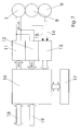
- the measuring cell in this case has a closed housing 7, which is divided by a partition 6 into two chambers 3, 4 of equal size. Inserted into the partition wall 6 are an open channel 2 well-defined by its dimensions and a sound transducer 1.
- the gaseous medium to be measured enters and exits the housing 7 through comparatively thin and long supply pipes 5.
- By measuring the electrical impedance of the sound transducer 1 over the frequency are after detailed correction and conversion in addition to the operating density of the operating sound velocity and possibly the dynamic viscosity (hereinafter but not specified) derivable.
- By optional additional detection of the operating pressure and the operating temperature by means of suitable sensors 8, 9, wherein the pressure transducer is connected via a connecting line 10 with one of the chambers 3, 4, can be determined by calculation standard density and standard sound velocity.
- the sound transducer 1 has a vibratable membrane with an effective membrane area S M.
- the membrane can either move like a piston or perform a 1st order bending vibration. Regardless of the mode of movement of the membrane, this is additionally described by its mass m M and the acting compliance C M. This results in a vibratory system with the resonant frequency f 0 .
- f 0 1 2 ⁇ ⁇ ⁇ 1 C M ⁇ m M
- the membrane By installing the sound transducer 1 in the closed housing 7, the membrane is loaded by the same large volumes V of the two housing chambers 3, 4. If one thinks of the open channel 2 as not present, then the two volumes V act as additional compliances C V , which increase the resonance frequency of the membrane.
- f 2 1 2 ⁇ ⁇ ⁇ 2 ⁇ S K ⁇ ⁇ ⁇ P B V ⁇ l K ⁇ ⁇ B
- the operating density ⁇ B results from the known and long-term stable geometric variables S K , S M and l K and the membrane mass m M of the sound transducer.
- the operating sound velocity c B is also based on the long-term stable geometric variables V, l K and S K.
- the cross section of the open channel should be larger than one tenth of the membrane area in order to keep the mechanical losses small (R 2 as small as possible).
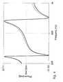
- FIG. 5 shows the phase responses with out-calculated L 0 when halving and doubling the operating density compared to the normal state, assuming identical sound velocities.
- FIG. 6 shows the phase responses at 0.71 times and 1.41 times the speed of sound, assuming identical operating densities.
- Illustrated clearly consists of the output sequence A (n) and thus the current signal i (t) of a frequency spectrum formed by discrete frequencies of the same amplitude and optimally distributed different phase position.
- the smallest occurring frequency, identical to the distance of the discrete frequencies from each other, is f p 1 / t p .
- the different phase position of the individual frequencies to each other is optimal in the sense that the ratio of RMS value and peak value of the current signal is maximum.
- the complex impedance of the transducer Z (f) is to be determined by discrete complex division of U (f) by l (f).
- a signal sampling rate f s of at least 3000 Hz is necessary.
- the speed of sound and the density can be measured about 1.5 times per second. By averaging over several measurements, the scattering can be reduced.
- An extension of the method can take place in that the determined values for operating density and operating sound velocity are converted to the standard values as shown below.
- the standard density ⁇ n and the standard sound velocity c n are calculated.
- P n and T n define the standard state. As long as T B and T n and P B and P n are not more than 20% apart, the error due to the real gas behavior is less than 0.1%.
- the data acquisition in the evaluation unit 16 of the pressure and temperature transducer 8, 9 generated electrical signals 14, 15 done by means of A / D conversion in a double converter module 13 and thus the evaluation unit 16, the measured values are digitally available.
- To operate the evaluation unit 16 is an optional control unit 17 and for connection to the power supply, a supply unit 19 and a communication unit 18 for forwarding the determined values available.
Applications Claiming Priority (1)
| Application Number | Priority Date | Filing Date | Title |
|---|---|---|---|
| DE102006013809A DE102006013809B3 (de) | 2006-03-22 | 2006-03-22 | Verfahren und Vorrichtung zur Messung von Betriebsdichte und/oder Betriebsschallgeschwindigkeit in einem gasförmigen Medium |
Publications (3)
| Publication Number | Publication Date |
|---|---|
| EP1837649A2 true EP1837649A2 (fr) | 2007-09-26 |
| EP1837649A3 EP1837649A3 (fr) | 2008-06-25 |
| EP1837649B1 EP1837649B1 (fr) | 2011-02-09 |
Family
ID=38289978
Family Applications (1)
| Application Number | Title | Priority Date | Filing Date |
|---|---|---|---|
| EP07005104A Not-in-force EP1837649B1 (fr) | 2006-03-22 | 2007-03-13 | Procédé et dispositif destinés à la mesure de la densité d'un milieu gazeux et/ou de la vitesse du son dans un milieu gazeux. |
Country Status (4)
| Country | Link |
|---|---|
| US (1) | US7647826B2 (fr) |
| EP (1) | EP1837649B1 (fr) |
| AT (1) | ATE498128T1 (fr) |
| DE (2) | DE102006013809B3 (fr) |
Families Citing this family (6)
| Publication number | Priority date | Publication date | Assignee | Title |
|---|---|---|---|---|
| EP1707940A1 (fr) * | 2005-03-31 | 2006-10-04 | Ecole Polytechnique Fédérale de Lausanne (EPFL) | Capteur de viscosité de gaz |
| US10365136B2 (en) * | 2014-08-20 | 2019-07-30 | Halliburton Energy Services, Inc. | Opto-acoustic flowmeter for use in subterranean wells |
| CA2954736C (fr) * | 2014-08-20 | 2020-01-14 | Halliburton Energy Services, Inc. | Detection d'ecoulement dans des puits souterrains |
| US11029297B2 (en) * | 2018-08-08 | 2021-06-08 | Applied Materials, Inc. | Method of gas composition determination, adjustment, and usage |
| DE102018127526A1 (de) * | 2018-11-05 | 2020-05-07 | Endress+Hauser SE+Co. KG | Vibronischer Multisensor |
| CN113091877B (zh) * | 2021-04-07 | 2023-07-14 | 上海海洋大学 | 控压式水中声学散射体目标强度测定装置及方法 |
Citations (3)
| Publication number | Priority date | Publication date | Assignee | Title |
|---|---|---|---|---|
| FR2493984A1 (fr) * | 1980-11-12 | 1982-05-14 | Centre Electron Horloger | Transducteur de pression a element vibrant |
| DE3741558A1 (de) * | 1986-12-17 | 1988-07-07 | Fuji Electric Co Ltd | Vorrichtung zur erfassung der resonanzfrequenz eines mit einem fluid in beruehrung stehenden schwingenden organs |
| US4803671A (en) * | 1986-07-30 | 1989-02-07 | Siemens Aktiengesellschaft | Sensor for acoustic shockwave pulses |
Family Cites Families (2)
| Publication number | Priority date | Publication date | Assignee | Title |
|---|---|---|---|---|
| SE526927C2 (sv) * | 2003-11-24 | 2005-11-22 | Hoek Instr Ab | Realtidsanalys av gasblandningar |
| US7707877B2 (en) * | 2004-03-24 | 2010-05-04 | Kyoto University | Volume measuring device and method |
-
2006
- 2006-03-22 DE DE102006013809A patent/DE102006013809B3/de not_active Expired - Fee Related
-
2007
- 2007-03-13 AT AT07005104T patent/ATE498128T1/de active
- 2007-03-13 EP EP07005104A patent/EP1837649B1/fr not_active Not-in-force
- 2007-03-13 DE DE502007006439T patent/DE502007006439D1/de active Active
- 2007-03-21 US US11/726,221 patent/US7647826B2/en not_active Expired - Fee Related
Patent Citations (3)
| Publication number | Priority date | Publication date | Assignee | Title |
|---|---|---|---|---|
| FR2493984A1 (fr) * | 1980-11-12 | 1982-05-14 | Centre Electron Horloger | Transducteur de pression a element vibrant |
| US4803671A (en) * | 1986-07-30 | 1989-02-07 | Siemens Aktiengesellschaft | Sensor for acoustic shockwave pulses |
| DE3741558A1 (de) * | 1986-12-17 | 1988-07-07 | Fuji Electric Co Ltd | Vorrichtung zur erfassung der resonanzfrequenz eines mit einem fluid in beruehrung stehenden schwingenden organs |
Non-Patent Citations (1)
| Title |
|---|
| GILLIS KEITH A ET AL: "Theory of the Greenspan viscometer" JOURNAL OF THE ACOUSTICAL SOCIETY OF AMERICA, AIP / ACOUSTICAL SOCIETY OF AMERICA, MELVILLE, NY, US, Bd. 114, Nr. 1, 1. Juli 2003 (2003-07-01), Seiten 166-173, XP012003533 ISSN: 0001-4966 * |
Also Published As
| Publication number | Publication date |
|---|---|
| ATE498128T1 (de) | 2011-02-15 |
| DE502007006439D1 (de) | 2011-03-24 |
| EP1837649B1 (fr) | 2011-02-09 |
| EP1837649A3 (fr) | 2008-06-25 |
| DE102006013809B3 (de) | 2007-09-06 |
| US20070220976A1 (en) | 2007-09-27 |
| US7647826B2 (en) | 2010-01-19 |
Similar Documents
| Publication | Publication Date | Title |
|---|---|---|
| DE69907913T2 (de) | Kreuzmessen von akustischen signalen eines durchflussmessers | |
| EP3877732B1 (fr) | Multicapteur vibronique | |
| EP2356408B1 (fr) | Procédé et dispositif d'étalonnage de transducteurs de mesure de débitmètres à ultrasons | |
| DE102011004668B4 (de) | Ultraschalldurchflussmessgerät | |
| EP1837649B1 (fr) | Procédé et dispositif destinés à la mesure de la densité d'un milieu gazeux et/ou de la vitesse du son dans un milieu gazeux. | |
| EP2798319B1 (fr) | Dispositif de détermination et/ou de surveillance d'au moins une grandeur de processus | |
| DE102019124709A1 (de) | Verfahren zum Betreiben eines Messgerätes mit mindestens einem Oszillator und Messgerät zur Durchführung des Verfahrens | |
| EP3045877B1 (fr) | Procédé de fonctionnement d'un appareil de mesure de débit massique coriolis | |
| DE102012011934B4 (de) | Verfahren zum Betreiben eines Resonazmesssystems und diesbezügliche Resonanzmesssystem | |
| EP1812775A1 (fr) | Circuit de mesure et de commande pour un debitmetre a effet coriolis comportant trois canaux de mesure | |
| DE102005037458B4 (de) | Ultraschall-Strömungssensor mit Driftkompensation | |
| EP3421950B1 (fr) | Capteur de débit, procédé et débitmètre destinés à la détermination de vitesses des phases d'un milieu multiphase | |
| DE102018102535B3 (de) | Temperaturmessung mittels der Impedanz eines Ultraschalltransducers | |
| EP3657138B1 (fr) | Procédé de fonctionnement d'un dispositif de mesure et dispositif de mesure | |
| EP3314210B1 (fr) | Appareil émetteur de champs doté d'un circuit de compensation pour l'élimination des impacts environnementaux | |
| DE69737879T3 (de) | Durchflussmesser und Verfahren zum Betreiben eines Durchflussmessers | |
| EP3729074B1 (fr) | Procédé et dispositif de mesure de la matière grasse du lait | |
| EP2884244B1 (fr) | Procédé de fonctionnement d'un débitmètre massique Coriolis | |
| WO2006056560A2 (fr) | Procede pour determiner le debit massique d'un debitmetre massique coriolis | |
| WO2008152060A1 (fr) | Procédé pour mesurer et/ou surveiller un paramètre d'écoulement et dispositif correspondant | |
| WO1997042509A1 (fr) | Procede pour mesurer la vitesse d'ecoulement de milieux gazeux ou liquides a l'aide d'ultrasons, et dispositif de mesure convenant a la mise en oeuvre du procede | |
| DE10131823A1 (de) | Miniaturanordnung zur Messung der akustischen Impedanz | |
| DE102015003196B4 (de) | Vorrichtung und Verfahren zur Restwertverarbeitung bei der Ansteuerung eines Sensors | |
| EP4078164A1 (fr) | Procédé pour la caractérisation de la charge de gaz d'un milieu et densimètre à cet effet | |
| WO2003004979A1 (fr) | Procede pour determiner le debit massique d'un debitmetre massique de coriolis |
Legal Events
| Date | Code | Title | Description |
|---|---|---|---|
| PUAI | Public reference made under article 153(3) epc to a published international application that has entered the european phase |
Free format text: ORIGINAL CODE: 0009012 |
|
| AK | Designated contracting states |
Kind code of ref document: A2 Designated state(s): AT BE BG CH CY CZ DE DK EE ES FI FR GB GR HU IE IS IT LI LT LU LV MC MT NL PL PT RO SE SI SK TR |
|
| AX | Request for extension of the european patent |
Extension state: AL BA HR MK YU |
|
| RAP1 | Party data changed (applicant data changed or rights of an application transferred) |
Owner name: ELSTER GMBH |
|
| PUAL | Search report despatched |
Free format text: ORIGINAL CODE: 0009013 |
|
| AK | Designated contracting states |
Kind code of ref document: A3 Designated state(s): AT BE BG CH CY CZ DE DK EE ES FI FR GB GR HU IE IS IT LI LT LU LV MC MT NL PL PT RO SE SI SK TR |
|
| AX | Request for extension of the european patent |
Extension state: AL BA HR MK RS |
|
| 17P | Request for examination filed |
Effective date: 20080924 |
|
| 17Q | First examination report despatched |
Effective date: 20081023 |
|
| AKX | Designation fees paid |
Designated state(s): AT BE BG CH CY CZ DE DK EE ES FI FR GB GR HU IE IS IT LI LT LU LV MC MT NL PL PT RO SE SI SK TR |
|
| GRAP | Despatch of communication of intention to grant a patent |
Free format text: ORIGINAL CODE: EPIDOSNIGR1 |
|
| GRAS | Grant fee paid |
Free format text: ORIGINAL CODE: EPIDOSNIGR3 |
|
| GRAA | (expected) grant |
Free format text: ORIGINAL CODE: 0009210 |
|
| AK | Designated contracting states |
Kind code of ref document: B1 Designated state(s): AT BE BG CH CY CZ DE DK EE ES FI FR GB GR HU IE IS IT LI LT LU LV MC MT NL PL PT RO SE SI SK TR |
|
| REG | Reference to a national code |
Ref country code: GB Ref legal event code: FG4D Free format text: NOT ENGLISH |
|
| REG | Reference to a national code |
Ref country code: CH Ref legal event code: EP |
|
| REG | Reference to a national code |
Ref country code: IE Ref legal event code: FG4D Free format text: LANGUAGE OF EP DOCUMENT: GERMAN |
|
| REF | Corresponds to: |
Ref document number: 502007006439 Country of ref document: DE Date of ref document: 20110324 Kind code of ref document: P |
|
| REG | Reference to a national code |
Ref country code: DE Ref legal event code: R096 Ref document number: 502007006439 Country of ref document: DE Effective date: 20110324 |
|
| REG | Reference to a national code |
Ref country code: NL Ref legal event code: T3 |
|
| LTIE | Lt: invalidation of european patent or patent extension |
Effective date: 20110209 |
|
| PG25 | Lapsed in a contracting state [announced via postgrant information from national office to epo] |
Ref country code: LT Free format text: LAPSE BECAUSE OF FAILURE TO SUBMIT A TRANSLATION OF THE DESCRIPTION OR TO PAY THE FEE WITHIN THE PRESCRIBED TIME-LIMIT Effective date: 20110209 Ref country code: GR Free format text: LAPSE BECAUSE OF FAILURE TO SUBMIT A TRANSLATION OF THE DESCRIPTION OR TO PAY THE FEE WITHIN THE PRESCRIBED TIME-LIMIT Effective date: 20110510 Ref country code: LV Free format text: LAPSE BECAUSE OF FAILURE TO SUBMIT A TRANSLATION OF THE DESCRIPTION OR TO PAY THE FEE WITHIN THE PRESCRIBED TIME-LIMIT Effective date: 20110209 Ref country code: SE Free format text: LAPSE BECAUSE OF FAILURE TO SUBMIT A TRANSLATION OF THE DESCRIPTION OR TO PAY THE FEE WITHIN THE PRESCRIBED TIME-LIMIT Effective date: 20110209 Ref country code: ES Free format text: LAPSE BECAUSE OF FAILURE TO SUBMIT A TRANSLATION OF THE DESCRIPTION OR TO PAY THE FEE WITHIN THE PRESCRIBED TIME-LIMIT Effective date: 20110520 Ref country code: PT Free format text: LAPSE BECAUSE OF FAILURE TO SUBMIT A TRANSLATION OF THE DESCRIPTION OR TO PAY THE FEE WITHIN THE PRESCRIBED TIME-LIMIT Effective date: 20110609 |
|
| PG25 | Lapsed in a contracting state [announced via postgrant information from national office to epo] |
Ref country code: BG Free format text: LAPSE BECAUSE OF FAILURE TO SUBMIT A TRANSLATION OF THE DESCRIPTION OR TO PAY THE FEE WITHIN THE PRESCRIBED TIME-LIMIT Effective date: 20110509 Ref country code: PL Free format text: LAPSE BECAUSE OF FAILURE TO SUBMIT A TRANSLATION OF THE DESCRIPTION OR TO PAY THE FEE WITHIN THE PRESCRIBED TIME-LIMIT Effective date: 20110209 Ref country code: FI Free format text: LAPSE BECAUSE OF FAILURE TO SUBMIT A TRANSLATION OF THE DESCRIPTION OR TO PAY THE FEE WITHIN THE PRESCRIBED TIME-LIMIT Effective date: 20110209 Ref country code: SI Free format text: LAPSE BECAUSE OF FAILURE TO SUBMIT A TRANSLATION OF THE DESCRIPTION OR TO PAY THE FEE WITHIN THE PRESCRIBED TIME-LIMIT Effective date: 20110209 Ref country code: CY Free format text: LAPSE BECAUSE OF FAILURE TO SUBMIT A TRANSLATION OF THE DESCRIPTION OR TO PAY THE FEE WITHIN THE PRESCRIBED TIME-LIMIT Effective date: 20110209 |
|
| REG | Reference to a national code |
Ref country code: IE Ref legal event code: FD4D |
|
| PG25 | Lapsed in a contracting state [announced via postgrant information from national office to epo] |
Ref country code: MC Free format text: LAPSE BECAUSE OF NON-PAYMENT OF DUE FEES Effective date: 20110331 Ref country code: IE Free format text: LAPSE BECAUSE OF FAILURE TO SUBMIT A TRANSLATION OF THE DESCRIPTION OR TO PAY THE FEE WITHIN THE PRESCRIBED TIME-LIMIT Effective date: 20110209 Ref country code: EE Free format text: LAPSE BECAUSE OF FAILURE TO SUBMIT A TRANSLATION OF THE DESCRIPTION OR TO PAY THE FEE WITHIN THE PRESCRIBED TIME-LIMIT Effective date: 20110209 Ref country code: DK Free format text: LAPSE BECAUSE OF FAILURE TO SUBMIT A TRANSLATION OF THE DESCRIPTION OR TO PAY THE FEE WITHIN THE PRESCRIBED TIME-LIMIT Effective date: 20110209 |
|
| REG | Reference to a national code |
Ref country code: CH Ref legal event code: PL |
|
| PG25 | Lapsed in a contracting state [announced via postgrant information from national office to epo] |
Ref country code: SK Free format text: LAPSE BECAUSE OF FAILURE TO SUBMIT A TRANSLATION OF THE DESCRIPTION OR TO PAY THE FEE WITHIN THE PRESCRIBED TIME-LIMIT Effective date: 20110209 Ref country code: RO Free format text: LAPSE BECAUSE OF FAILURE TO SUBMIT A TRANSLATION OF THE DESCRIPTION OR TO PAY THE FEE WITHIN THE PRESCRIBED TIME-LIMIT Effective date: 20110209 Ref country code: CZ Free format text: LAPSE BECAUSE OF FAILURE TO SUBMIT A TRANSLATION OF THE DESCRIPTION OR TO PAY THE FEE WITHIN THE PRESCRIBED TIME-LIMIT Effective date: 20110209 |
|
| PLBE | No opposition filed within time limit |
Free format text: ORIGINAL CODE: 0009261 |
|
| STAA | Information on the status of an ep patent application or granted ep patent |
Free format text: STATUS: NO OPPOSITION FILED WITHIN TIME LIMIT |
|
| PG25 | Lapsed in a contracting state [announced via postgrant information from national office to epo] |
Ref country code: MT Free format text: LAPSE BECAUSE OF FAILURE TO SUBMIT A TRANSLATION OF THE DESCRIPTION OR TO PAY THE FEE WITHIN THE PRESCRIBED TIME-LIMIT Effective date: 20110209 |
|
| 26N | No opposition filed |
Effective date: 20111110 |
|
| PG25 | Lapsed in a contracting state [announced via postgrant information from national office to epo] |
Ref country code: LI Free format text: LAPSE BECAUSE OF NON-PAYMENT OF DUE FEES Effective date: 20110331 Ref country code: CH Free format text: LAPSE BECAUSE OF NON-PAYMENT OF DUE FEES Effective date: 20110331 |
|
| REG | Reference to a national code |
Ref country code: DE Ref legal event code: R097 Ref document number: 502007006439 Country of ref document: DE Effective date: 20111110 |
|
| PG25 | Lapsed in a contracting state [announced via postgrant information from national office to epo] |
Ref country code: LU Free format text: LAPSE BECAUSE OF NON-PAYMENT OF DUE FEES Effective date: 20110313 |
|
| PG25 | Lapsed in a contracting state [announced via postgrant information from national office to epo] |
Ref country code: IS Free format text: LAPSE BECAUSE OF FAILURE TO SUBMIT A TRANSLATION OF THE DESCRIPTION OR TO PAY THE FEE WITHIN THE PRESCRIBED TIME-LIMIT Effective date: 20110209 |
|
| PG25 | Lapsed in a contracting state [announced via postgrant information from national office to epo] |
Ref country code: TR Free format text: LAPSE BECAUSE OF FAILURE TO SUBMIT A TRANSLATION OF THE DESCRIPTION OR TO PAY THE FEE WITHIN THE PRESCRIBED TIME-LIMIT Effective date: 20110209 |
|
| PG25 | Lapsed in a contracting state [announced via postgrant information from national office to epo] |
Ref country code: HU Free format text: LAPSE BECAUSE OF FAILURE TO SUBMIT A TRANSLATION OF THE DESCRIPTION OR TO PAY THE FEE WITHIN THE PRESCRIBED TIME-LIMIT Effective date: 20110209 |
|
| PGFP | Annual fee paid to national office [announced via postgrant information from national office to epo] |
Ref country code: NL Payment date: 20140122 Year of fee payment: 8 |
|
| PGFP | Annual fee paid to national office [announced via postgrant information from national office to epo] |
Ref country code: AT Payment date: 20140311 Year of fee payment: 8 Ref country code: IT Payment date: 20140306 Year of fee payment: 8 Ref country code: FR Payment date: 20140214 Year of fee payment: 8 |
|
| PGFP | Annual fee paid to national office [announced via postgrant information from national office to epo] |
Ref country code: GB Payment date: 20140318 Year of fee payment: 8 |
|
| PGFP | Annual fee paid to national office [announced via postgrant information from national office to epo] |
Ref country code: BE Payment date: 20140502 Year of fee payment: 8 |
|
| REG | Reference to a national code |
Ref country code: AT Ref legal event code: MM01 Ref document number: 498128 Country of ref document: AT Kind code of ref document: T Effective date: 20150313 |
|
| GBPC | Gb: european patent ceased through non-payment of renewal fee |
Effective date: 20150313 |
|
| REG | Reference to a national code |
Ref country code: NL Ref legal event code: MM Effective date: 20150401 |
|
| PG25 | Lapsed in a contracting state [announced via postgrant information from national office to epo] |
Ref country code: IT Free format text: LAPSE BECAUSE OF NON-PAYMENT OF DUE FEES Effective date: 20150313 |
|
| REG | Reference to a national code |
Ref country code: FR Ref legal event code: ST Effective date: 20151130 |
|
| PG25 | Lapsed in a contracting state [announced via postgrant information from national office to epo] |
Ref country code: GB Free format text: LAPSE BECAUSE OF NON-PAYMENT OF DUE FEES Effective date: 20150313 |
|
| PG25 | Lapsed in a contracting state [announced via postgrant information from national office to epo] |
Ref country code: AT Free format text: LAPSE BECAUSE OF NON-PAYMENT OF DUE FEES Effective date: 20150313 Ref country code: FR Free format text: LAPSE BECAUSE OF NON-PAYMENT OF DUE FEES Effective date: 20150331 |
|
| PG25 | Lapsed in a contracting state [announced via postgrant information from national office to epo] |
Ref country code: NL Free format text: LAPSE BECAUSE OF NON-PAYMENT OF DUE FEES Effective date: 20150401 |
|
| PG25 | Lapsed in a contracting state [announced via postgrant information from national office to epo] |
Ref country code: BE Free format text: LAPSE BECAUSE OF NON-PAYMENT OF DUE FEES Effective date: 20150331 |
|
| PGFP | Annual fee paid to national office [announced via postgrant information from national office to epo] |
Ref country code: DE Payment date: 20190213 Year of fee payment: 13 |
|
| PGFP | Annual fee paid to national office [announced via postgrant information from national office to epo] |
Ref country code: DE Payment date: 20190213 Year of fee payment: 13 |
|
| REG | Reference to a national code |
Ref country code: DE Ref legal event code: R119 Ref document number: 502007006439 Country of ref document: DE |
|
| PG25 | Lapsed in a contracting state [announced via postgrant information from national office to epo] |
Ref country code: DE Free format text: LAPSE BECAUSE OF NON-PAYMENT OF DUE FEES Effective date: 20201001 |