EP1837207A1 - Pneumatic tire - Google Patents
Pneumatic tire Download PDFInfo
- Publication number
- EP1837207A1 EP1837207A1 EP06711676A EP06711676A EP1837207A1 EP 1837207 A1 EP1837207 A1 EP 1837207A1 EP 06711676 A EP06711676 A EP 06711676A EP 06711676 A EP06711676 A EP 06711676A EP 1837207 A1 EP1837207 A1 EP 1837207A1
- Authority
- EP
- European Patent Office
- Prior art keywords
- tire
- sipes
- blocks
- length
- dimensional
- Prior art date
- Legal status (The legal status is an assumption and is not a legal conclusion. Google has not performed a legal analysis and makes no representation as to the accuracy of the status listed.)
- Granted
Links
Images


Classifications
-
- B—PERFORMING OPERATIONS; TRANSPORTING
- B60—VEHICLES IN GENERAL
- B60C—VEHICLE TYRES; TYRE INFLATION; TYRE CHANGING; CONNECTING VALVES TO INFLATABLE ELASTIC BODIES IN GENERAL; DEVICES OR ARRANGEMENTS RELATED TO TYRES
- B60C11/00—Tyre tread bands; Tread patterns; Anti-skid inserts
- B60C11/03—Tread patterns
- B60C11/12—Tread patterns characterised by the use of narrow slits or incisions, e.g. sipes
- B60C11/1204—Tread patterns characterised by the use of narrow slits or incisions, e.g. sipes with special shape of the sipe
- B60C11/1218—Three-dimensional shape with regard to depth and extending direction
-
- B—PERFORMING OPERATIONS; TRANSPORTING
- B60—VEHICLES IN GENERAL
- B60C—VEHICLE TYRES; TYRE INFLATION; TYRE CHANGING; CONNECTING VALVES TO INFLATABLE ELASTIC BODIES IN GENERAL; DEVICES OR ARRANGEMENTS RELATED TO TYRES
- B60C11/00—Tyre tread bands; Tread patterns; Anti-skid inserts
- B60C11/03—Tread patterns
- B60C11/12—Tread patterns characterised by the use of narrow slits or incisions, e.g. sipes
- B60C11/1259—Depth of the sipe
- B60C11/1263—Depth of the sipe different within the same sipe
-
- B—PERFORMING OPERATIONS; TRANSPORTING
- B60—VEHICLES IN GENERAL
- B60C—VEHICLE TYRES; TYRE INFLATION; TYRE CHANGING; CONNECTING VALVES TO INFLATABLE ELASTIC BODIES IN GENERAL; DEVICES OR ARRANGEMENTS RELATED TO TYRES
- B60C11/00—Tyre tread bands; Tread patterns; Anti-skid inserts
- B60C11/03—Tread patterns
- B60C11/12—Tread patterns characterised by the use of narrow slits or incisions, e.g. sipes
- B60C11/1204—Tread patterns characterised by the use of narrow slits or incisions, e.g. sipes with special shape of the sipe
- B60C2011/1213—Tread patterns characterised by the use of narrow slits or incisions, e.g. sipes with special shape of the sipe sinusoidal or zigzag at the tread surface
-
- B—PERFORMING OPERATIONS; TRANSPORTING
- B60—VEHICLES IN GENERAL
- B60C—VEHICLE TYRES; TYRE INFLATION; TYRE CHANGING; CONNECTING VALVES TO INFLATABLE ELASTIC BODIES IN GENERAL; DEVICES OR ARRANGEMENTS RELATED TO TYRES
- B60C11/00—Tyre tread bands; Tread patterns; Anti-skid inserts
- B60C11/03—Tread patterns
- B60C11/12—Tread patterns characterised by the use of narrow slits or incisions, e.g. sipes
- B60C11/1272—Width of the sipe
- B60C2011/1286—Width of the sipe being different from sipe to sipe
-
- Y—GENERAL TAGGING OF NEW TECHNOLOGICAL DEVELOPMENTS; GENERAL TAGGING OF CROSS-SECTIONAL TECHNOLOGIES SPANNING OVER SEVERAL SECTIONS OF THE IPC; TECHNICAL SUBJECTS COVERED BY FORMER USPC CROSS-REFERENCE ART COLLECTIONS [XRACs] AND DIGESTS
- Y10—TECHNICAL SUBJECTS COVERED BY FORMER USPC
- Y10S—TECHNICAL SUBJECTS COVERED BY FORMER USPC CROSS-REFERENCE ART COLLECTIONS [XRACs] AND DIGESTS
- Y10S152/00—Resilient tires and wheels
- Y10S152/03—Slits in threads
-
- Y—GENERAL TAGGING OF NEW TECHNOLOGICAL DEVELOPMENTS; GENERAL TAGGING OF CROSS-SECTIONAL TECHNOLOGIES SPANNING OVER SEVERAL SECTIONS OF THE IPC; TECHNICAL SUBJECTS COVERED BY FORMER USPC CROSS-REFERENCE ART COLLECTIONS [XRACs] AND DIGESTS
- Y10—TECHNICAL SUBJECTS COVERED BY FORMER USPC
- Y10S—TECHNICAL SUBJECTS COVERED BY FORMER USPC CROSS-REFERENCE ART COLLECTIONS [XRACs] AND DIGESTS
- Y10S152/00—Resilient tires and wheels
- Y10S152/902—Non-directional tread pattern having no circumferential rib and having blocks defined by circumferential grooves and transverse grooves
Definitions
- the present invention relates to a pneumatic tire that includes a plurality of grooves extending at least in the circumferential direction in a tread portion, and that also includes a plurality of blocks formed by the grooves.
- each block is divided along the tire width direction. Accordingly, although the starting and braking performances on snow are improved, the rigidity of the block is made insufficient. This leads to a problem of an insufficient stability in straight running on the dry road surface.
- an object of the present invention is to provide a pneumatic tire that achieves a highly good balance between the stability in straight running on the dry road surface and the starting and braking performances on snow.
- an aspect of the present invention is a pneumatic tire including a plurality of grooves extending at least in the circumferential direction in a tread portion of the tire and sipes in a plurality of blocks formed by the grooves.
- the pneumatic tire has the following characteristics.
- the groove width of each sipe formed in each of the blocks constituting a center region of the tread portion is greater than the groove width of a sipe formed in each of the blocks constituting edge regions of the tread portion.
- At least the sipes formed in the blocks constituting the center region are three-dimensional sipes having a zigzag shape extending in the tire width direction, in the tire circumferential direction, and in the tire radial direction.
- Each of the three-dimensional sipes is provided with, on the inner side thereof in the tire radial direction, at least one cutout which has a length, in the tire radial direction, of 50 to 90% of the length of the three-dimensional sipe in the tire radial direction, and which has a length, in the tire width direction, of 1 to 5 mm.
- the groove width of a sipe formed in each of the blocks constituting a center region of the tread portion is greater than the groove width of a sipe formed in each of the blocks constituting an edge region of the tread portion. Accordingly, the sipes each having the greater groove width can function like grooves. Specifically, at the time of running on snow, the sipes, each having the greater groove width, compress the snow to increase the friction between the tread portion and the road surface, like the grooves. As a result, the starting and braking performances can be improved.
- the groove width of the sipes formed in the blocks constituting the center region of the tread portion is greater than the groove width of each of the sipes formed in the blocks constituting the edge regions of the tread portion, the rigidity of the block is decreased. Accordingly, the stability in straight running on the dry road surface is decreased.
- at least the sipes formed in the blocks constituting the center region are the three-dimensional sipes having a zigzag shape extending in the width, circumferential and radial directions of the tire, adjacent portions of the blocks stick on each other when the block falls down. Accordingly, the rigidity of the block is improved, and thus the stability in straight running on the dry road surface is also improved.
- each of the three-dimensional sipes is provided with, on the inner side thereof in the tire radial direction, at least one cutout which has a length, in the tire radial direction, of 50 to 90% of the length of the three-dimensional sipe in the tire radial direction. Further, the cutout has a length, in the tire width direction, of 1 to 5 mm. Accordingly, the depth of part of the three-dimensional sipe can be reduced, and thus the rigidity of the block can be further improved. As a result, the stability in straight running on the dry road surface increases.
- the degree of improvement in the stability in straight running on the dry road surface is small.
- the length is greater than 5 mm, the rigidity of the block is excessively high. As a result, the starting and braking performances on snow cannot be improved.
- a cutout which is closer to the tire equator line, has a length in the tire radial direction greater than the length in the tire radial direction of another cutout.
- the cutout which is closer to the tire equator line, has a length in the tire radial direction greater than the length in the tire radial direction of another cutout, the rigidity of the block on the tire equator line side can be further improved. As a result, it is possible to suppress the reduction in the stability in straight running on the dry road surface.
- Fig. 1 is a diagram showing a tread portion of the pneumatic tire 1 according to the present embodiment.
- circumferential-direction grooves 2 In the tread portion of the pneumatic tire 1, circumferential-direction grooves 2, width-direction grooves 3 and blocks 4 are formed.
- the circumferential-direction grooves 2 are grooves extending in the tire circumferential direction (a direction indicated by an arrow S).
- the width-direction grooves 3 are grooves extending in the tire width direction (a direction indicated by an arrow W).
- the circumferential-direction groove 2 intersects the width-direction grooves 3 so as to form the blocks 4.
- the blocks 4 are provided with a sipe 5.
- the blocks 4 include center-region blocks 4a and edge-region blocks 4b.
- the center-region blocks 4a are blocks formed in a center region A of the tread portion.
- the edge-region blocks 4b are blocks formed in edge regions B of the tread portion.
- the groove-width of the sipes 5 formed in the center-region blocks 4a is greater than that of the sipes 5 formed in the edge-region blocks 4b.
- the sipes 5 formed in the center-region blocks 4a are three-dimensional sipes 5a having a zigzag shape extending in the tire width direction W, in the circumferential direction S, and in the tire radial direction.
- the three-dimensional sipes 5a will be described in detail later.
- the sipes 5 formed in the edge-region blocks 4b are linear sipes 5b, which is linear in the tire width direction.
- the sipes 5 formed in the edge-region blocks 4b are not limited to this, and may be the three-dimensional sipes 5a.
- each of the blocks 4 needs only to be a block defined by at least the circumferential-direction grooves 2, and the width-direction grooves 3 may not be formed in the tread portion.
- Fig. 2 is an enlarged diagram showing one of the three-dimensional sipes 5a according to the embodiment.
- each of the three-dimensional sipes 5a is a groove, and thus does not have any shape. Accordingly, the shape shown in the figure is a shape of a blade used for forming the three-dimensional sipe 5a.
- the three-dimensional sipe 5a having the shape is formed by removing the blade from the block 4.
- the three-dimensional sipe 5a has a zigzag shape extending in the tire width direction W, in the tire circumferential direction, and in the tire radial direction D. At least one cutout 6 is formed in the inner side portion, in the tire radial direction D, of each three-dimensional sipe 5a.
- the cutout 6 has a length in the tire radial direction D (hereinafter, referred to as the depth F or the length depth G of the cutout 6) of 50 to 90% of the length of the three-dimensional sipe 5a in the tire radial direction D (hereinafter, referred to as the depth E of the three-dimensional sipe 5a) , and also the cutout 6 has a length in the tire width direction W (hereinafter, referred to as the width I of the cutout 6) of 1 to 5 mm.
- the depth F of a center-side cutout 6a which is closer to the tire equator line, be greater than the depth G of an edge-side cutout 6b as shown in the figure.
- the groove width of the sipes 5 formed in the blocks 4 constituting the center region A of the tread portion is greater than the groove width of each of the sipes 5 formed in the blocks 4 constituting the edge regions B of the tread portion. Accordingly, the sipes 5 each having the greater groove width can function like grooves. Specifically, at the time of running on snow, the sipes having the greater groove width compress the snow to increase the friction between the tread portion and the road surface, like the grooves. As a result, the starting and braking performances can be improved.
- the groove width of each of the sipes 5 formed in the blocks 4 constituting the center region A of the tread portion is greater than the groove width of each of the sipes 5 formed in the blocks 4 constituting the edge regions B of the tread portion, the rigidity of the block 4 is decreased. Accordingly, the stability in straight running on the dry road surface is decreased.
- at least the sipes 5 formed in the blocks 4 constituting the center region A are the three-dimensional sipes 5a each having a zigzag shape extending in the tire width direction W, in the tire circumferential direction S, and in the tire radial direction D, adjacent portions of each of the blocks 4 stick on each other when the block 4 falls down.
- each of the three-dimensional sipes 5a is provided with, on the inner side thereof in the tire radial direction, at least one cutout 6 which has a length, in the tire radial direction, of 50 to 90% of the length of the three-dimensional sipe 5a in the tire radial direction. Further, the cutout 6 has a length, in the tire width direction, of 1 to 5 mm. Accordingly, the depth of part of the three-dimensional sipe 5a can be reduced, and thus the rigidity of the block 4 can be further improved. As a result, it is possible to improve the stability in straight running on the dry road surface.
- the length of each cutout in the tire radial direction is smaller than 50% of the length of each three-dimensional sipe in the tire radial direction, the depth of part of the three-dimensional sipe is not sufficiently reduced. Accordingly, the rigidity of the block cannot be sufficiently improved.
- the length of each cutout in the tire radial direction is greater than 90% of the length of each three-dimensional sipe in the tire radial direction, it is not possible to fulfill the function of the three-dimensional sipe. Accordingly, the starting and braking performances on snow cannot be improved.
- the length of each of the three-dimensional sipes in the tire width direction is less than 1 mm, a sufficient rigidity of the block cannot be obtained. Accordingly, the degree of improvement in the stability in straight running on the dry road surface is small.
- the length is greater than 5 mm, the rigidity of the block is excessively high. Accordingly, the starting and braking performances on snow cannot be improved.
- a pneumatic tire including a tread portion of the present invention (Example 1) was prepared.
- the pneumatic tire was attached to a wheel, and then the wheel with the pneumatic tire was mounted on a front-engine front-wheel-drive vehicle with an engine displacement of 1800 cc.
- the vehicle was tested to evaluate the starting performance and the braking performance on snow as well as the stability in straight running on the dry road surface.
- pneumatic tires of Comparative Example 1, Comparative Example 2 and Comparative Example 3 were also prepared, and were then tested under the same condition.
- Example 1 was the pneumatic tire of the present invention.
- This pneumatic tire is provided with the three-dimensional sipe 5a in each of the center-region blocks 4a, and is also provided with the linear sipe 5b in each of the edge-region blocks 4b.
- Each of the three-dimensional sipes 5a formed respectively in the center-region blocks 4a has the shape shown in Fig. 2, a groove width of 2. 0 mm and two cutouts formed therein.
- the depth F of the center-side cutout 6a is 5.5 mm while the depth G of the edge-side cutout 6b is 4.0 mm.
- the linear sipe 5b formed in the edge-region blocks 4b has a groove width of 0.7 mm.
- each of center-region blocks 40a and edge-region blocks 40b has a linear sipe 50 (50a and 50b) .
- the linear sipes 50a each formed in the center-region blocks 40a and the linear sipes 50b each formed in the edge-region blocks 40b have a groove width of 0.7 mm.
- each of the center-region blocks 40a and the edge-region blocks 40b has the linear sipe 50 (50a and 50b).
- the groove width of the linear sipe 50a formed in the center-region blocks 40a is 2.0 mm while the groove width of the linear sipe 50b formed in the edge-region blocks 40b is 0.7 mm.
- each of the center-region blocks 40a has the three-dimensional sipe 50a while each of the edge-region blocks 40b has the linear sipe 50b.
- the groove width of the three-dimensional sipe 50a is 2.0 mm while the groove width of the linear sipe 50b is 0.7 mm.
- the size of the rim was 15 ⁇ 6J, and the size of the tire was 205/60 R15 91T.
- the depth of the sipe 50 formed in the blocks 40 was 6.5 mm.
- the wheel was started to measure the time taken to increase the speed from 0 km/h to 25 km/h. Incidentally, the shorter time means more excellent the starting performance on snow.
- the wheel was braked to measure the distance taken to decrease the speed from 25 km/h to 0 km/h.
- the shorted distance means more excellent braking performance on snow.
- the vehicle was driven by a professional test driver, and the stability of the vehicle during straight running was evaluated to be rated from 0 to 10. Incidentally, the higher the rated value means more excellent stability in straight speed on the dry road surface.
- Example 1 is significantly improved in the starting performance and the braking performance on snow (hereinafter, the starting and braking performances on snow) while being substantially the same in the stability in straight running on the dry road surface.
- Example 1 is significantly improved in the stability in straight running on the dry road surface while being substantially the same in the starting and braking performances on snow.
- Example 1 is improved in the stability in straight running on the dry road surface while being substantially the same in the starting and braking performances on snow
Landscapes
- Engineering & Computer Science (AREA)
- Mechanical Engineering (AREA)
- Tires In General (AREA)
Abstract
Description
- The present invention relates to a pneumatic tire that includes a plurality of grooves extending at least in the circumferential direction in a tread portion, and that also includes a plurality of blocks formed by the grooves.
- Conventionally, a pneumatic tire including sipes, which are narrow slits, in blocks formed in a tread portion has been known.
- In addition, in recent years, there has been a pneumatic tire including three-dimensional sipes each formed into a zigzag shape extending in the tire width direction, in the tire circumferential direction and in the tire radial direction (for example, refer to
Japanese Patent Application Laid-open Publication 2004-203128 - In a pneumatic tire including such three-dimensional sipes as described above, the surface of each block is divided along the tire width direction. Accordingly, although the starting and braking performances on snow are improved, the rigidity of the block is made insufficient. This leads to a problem of an insufficient stability in straight running on the dry road surface.
- For this reason, it has been tried to reduce the depth (the length in the tire radial direction) of the above-described three-dimensional sipes to improve the rigidity of the block so that the stability in straight running on the dry road surface can increase. However, in this case, as the block wears progressively, the depth of the three-dimensional sipes is further reduced, so that the rigidity of the block is excessively improved. As a result, a problem occurs that the starting and braking performances on snow are deteriorated.
- In view of the above-described problems, an object of the present invention is to provide a pneumatic tire that achieves a highly good balance between the stability in straight running on the dry road surface and the starting and braking performances on snow.
- For the purpose of solving the above-described problems, an aspect of the present invention is a pneumatic tire including a plurality of grooves extending at least in the circumferential direction in a tread portion of the tire and sipes in a plurality of blocks formed by the grooves. The pneumatic tire has the following characteristics. The groove width of each sipe formed in each of the blocks constituting a center region of the tread portion is greater than the groove width of a sipe formed in each of the blocks constituting edge regions of the tread portion. At least the sipes formed in the blocks constituting the center region are three-dimensional sipes having a zigzag shape extending in the tire width direction, in the tire circumferential direction, and in the tire radial direction. Each of the three-dimensional sipes is provided with, on the inner side thereof in the tire radial direction, at least one cutout which has a length, in the tire radial direction, of 50 to 90% of the length of the three-dimensional sipe in the tire radial direction, and which has a length, in the tire width direction, of 1 to 5 mm.
- In the pneumatic tire according to the aspect of the present invention, the groove width of a sipe formed in each of the blocks constituting a center region of the tread portion is greater than the groove width of a sipe formed in each of the blocks constituting an edge region of the tread portion. Accordingly, the sipes each having the greater groove width can function like grooves. Specifically, at the time of running on snow, the sipes, each having the greater groove width, compress the snow to increase the friction between the tread portion and the road surface, like the grooves. As a result, the starting and braking performances can be improved.
- On the other hand, since the groove width of the sipes formed in the blocks constituting the center region of the tread portion is greater than the groove width of each of the sipes formed in the blocks constituting the edge regions of the tread portion, the rigidity of the block is decreased. Accordingly, the stability in straight running on the dry road surface is decreased. However, since at least the sipes formed in the blocks constituting the center region are the three-dimensional sipes having a zigzag shape extending in the width, circumferential and radial directions of the tire, adjacent portions of the blocks stick on each other when the block falls down. Accordingly, the rigidity of the block is improved, and thus the stability in straight running on the dry road surface is also improved. Moreover, each of the three-dimensional sipes is provided with, on the inner side thereof in the tire radial direction, at least one cutout which has a length, in the tire radial direction, of 50 to 90% of the length of the three-dimensional sipe in the tire radial direction. Further, the cutout has a length, in the tire width direction, of 1 to 5 mm. Accordingly, the depth of part of the three-dimensional sipe can be reduced, and thus the rigidity of the block can be further improved. As a result, the stability in straight running on the dry road surface increases. Incidentally, when the length of each cutout in the tire radial direction is smaller than 50% of the length of each three-dimensional sipe in the tire radial direction, the depth of part of the three-dimensional sipe is not sufficiently reduced. Accordingly, the rigidity of the block cannot be sufficiently improved. On the other hand, when the length of each cutout in the tire radial direction is greater than 90% of the length of each three-dimensional sipe in the tire radial direction, it is not possible to fulfill the function of the three-dimensional sipe. Accordingly, the starting and braking performances on snow cannot be improved. Furthermore, when the length of the three-dimensional sipes in the tire width direction is less than 1 mm, a sufficient rigidity of the block cannot be obtained. Accordingly, the degree of improvement in the stability in straight running on the dry road surface is small. On the other hand, when the length is greater than 5 mm, the rigidity of the block is excessively high. As a result, the starting and braking performances on snow cannot be improved.
- Moreover, it is preferable that, when two or more of the cutouts are formed, a cutout, which is closer to the tire equator line, has a length in the tire radial direction greater than the length in the tire radial direction of another cutout.
- When two or more of the cutouts are formed, since the cutout, which is closer to the tire equator line, has a length in the tire radial direction greater than the length in the tire radial direction of another cutout, the rigidity of the block on the tire equator line side can be further improved. As a result, it is possible to suppress the reduction in the stability in straight running on the dry road surface.
-
- [Fig. 1] Fig. 1 is a diagram showing a tread portion of a pneumatic tire according to an embodiment of the present invention.
- [Fig. 2] Fig. 2 is an enlarged diagram showing a three-dimensional sipe according to the embodiment of the present invention.
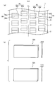
- [Fig. 3] Fig. 3 is a diagram showing a tread portion according to Comparative Example 1 of the present invention.
- [Fig. 4] Fig. 4 is a diagram showing a tread portion according to Comparative Example 2 of the present invention.
- [Fig. 5] Fig. 5 is a diagram showing a tread portion according to Comparative Example 3 of the present invention.
- Next, descriptions will be given of an embodiment of the present invention with reference to the drawings. In the following descriptions of the drawings, the same or similar parts are denoted by the same or similar reference numerals and symbols. However, the drawings are schematic, and thus it should be noted that dimensional proportions and the like are different from the real ones. Accordingly, specific sizes and the like should be determined in consideration of the following descriptions. In addition, it goes without saying that some parts are different in dimensional relationship and proportions between the drawings.
- Hereinafter, descriptions will be given of a
sipe 5 formed in apneumatic tire 1 according to the present embodiment. - Fig. 1 is a diagram showing a tread portion of the
pneumatic tire 1 according to the present embodiment. - In the tread portion of the
pneumatic tire 1, circumferential-direction grooves 2, width-direction grooves 3 andblocks 4 are formed. - The circumferential-
direction grooves 2 are grooves extending in the tire circumferential direction (a direction indicated by an arrow S). - The width-
direction grooves 3 are grooves extending in the tire width direction (a direction indicated by an arrow W). - The circumferential-
direction groove 2 intersects the width-direction grooves 3 so as to form theblocks 4. Theblocks 4 are provided with asipe 5. In addition, theblocks 4 include center-region blocks 4a and edge-region blocks 4b. - The center-
region blocks 4a are blocks formed in a center region A of the tread portion. - The edge-
region blocks 4b are blocks formed in edge regions B of the tread portion. - The groove-width of the
sipes 5 formed in the center-region blocks 4a is greater than that of thesipes 5 formed in the edge-region blocks 4b. In addition, at least, thesipes 5 formed in the center-region blocks 4a are three-dimensional sipes 5a having a zigzag shape extending in the tire width direction W, in the circumferential direction S, and in the tire radial direction. The three-dimensional sipes 5a will be described in detail later. On the other hand, in the figure, thesipes 5 formed in the edge-region blocks 4b arelinear sipes 5b, which is linear in the tire width direction. However, thesipes 5 formed in the edge-region blocks 4b are not limited to this, and may be the three-dimensional sipes 5a. - It should be noted that each of the
blocks 4 needs only to be a block defined by at least the circumferential-direction grooves 2, and the width-direction grooves 3 may not be formed in the tread portion. - Fig. 2 is an enlarged diagram showing one of the three-
dimensional sipes 5a according to the embodiment. - To be exact, each of the three-
dimensional sipes 5a is a groove, and thus does not have any shape. Accordingly, the shape shown in the figure is a shape of a blade used for forming the three-dimensional sipe 5a. The three-dimensional sipe 5a having the shape is formed by removing the blade from theblock 4. - As shown in the figure, the three-
dimensional sipe 5a has a zigzag shape extending in the tire width direction W, in the tire circumferential direction, and in the tire radial direction D. At least one cutout 6 is formed in the inner side portion, in the tire radial direction D, of each three-dimensional sipe 5a. The cutout 6 has a length in the tire radial direction D (hereinafter, referred to as the depth F or the length depth G of the cutout 6) of 50 to 90% of the length of the three-dimensional sipe 5a in the tire radial direction D (hereinafter, referred to as the depth E of the three-dimensional sipe 5a) , and also the cutout 6 has a length in the tire width direction W (hereinafter, referred to as the width I of the cutout 6) of 1 to 5 mm. - Moreover, in a case where two or more of the cutouts 6 are formed in each of the three-
dimensional sipes 5a, it is preferable that the depth F of a center-side cutout 6a, which is closer to the tire equator line, be greater than the depth G of an edge-side cutout 6b as shown in the figure. - In the
pneumatic tire 1 according to the present embodiment, the groove width of thesipes 5 formed in theblocks 4 constituting the center region A of the tread portion is greater than the groove width of each of thesipes 5 formed in theblocks 4 constituting the edge regions B of the tread portion. Accordingly, thesipes 5 each having the greater groove width can function like grooves. Specifically, at the time of running on snow, the sipes having the greater groove width compress the snow to increase the friction between the tread portion and the road surface, like the grooves. As a result, the starting and braking performances can be improved. - In addition, since the groove width of each of the
sipes 5 formed in theblocks 4 constituting the center region A of the tread portion is greater than the groove width of each of thesipes 5 formed in theblocks 4 constituting the edge regions B of the tread portion, the rigidity of theblock 4 is decreased. Accordingly, the stability in straight running on the dry road surface is decreased. However, since at least thesipes 5 formed in theblocks 4 constituting the center region A are the three-dimensional sipes 5a each having a zigzag shape extending in the tire width direction W, in the tire circumferential direction S, and in the tire radial direction D, adjacent portions of each of theblocks 4 stick on each other when theblock 4 falls down. Accordingly, the rigidity of theblock 4 is improved, and thus the stability in straight running on the dry road surface is improved. Moreover, each of the three-dimensional sipes 5a is provided with, on the inner side thereof in the tire radial direction, at least one cutout 6 which has a length, in the tire radial direction, of 50 to 90% of the length of the three-dimensional sipe 5a in the tire radial direction. Further, the cutout 6 has a length, in the tire width direction, of 1 to 5 mm. Accordingly, the depth of part of the three-dimensional sipe 5a can be reduced, and thus the rigidity of theblock 4 can be further improved. As a result, it is possible to improve the stability in straight running on the dry road surface. Incidentally, when the length of each cutout in the tire radial direction is smaller than 50% of the length of each three-dimensional sipe in the tire radial direction, the depth of part of the three-dimensional sipe is not sufficiently reduced. Accordingly, the rigidity of the block cannot be sufficiently improved. On the other hand, when the length of each cutout in the tire radial direction is greater than 90% of the length of each three-dimensional sipe in the tire radial direction, it is not possible to fulfill the function of the three-dimensional sipe. Accordingly, the starting and braking performances on snow cannot be improved. Furthermore, when the length of each of the three-dimensional sipes in the tire width direction is less than 1 mm, a sufficient rigidity of the block cannot be obtained. Accordingly, the degree of improvement in the stability in straight running on the dry road surface is small. On the other hand, when the length is greater than 5 mm, the rigidity of the block is excessively high. Accordingly, the starting and braking performances on snow cannot be improved. - in addition, in the case where two or more of the cutouts 6 are formed, since one of the cutouts 6, which is closer to the tire equator line, has a length in the tire radial direction greater than that of the other one of the cutouts 6, the rigidity of the block on the tire equator line side can be further improved. As a result, it is possible to suppress the reduction in the stability in straight running on the dry road surface.
- Hereinafter, descriptions will be given in detail of an example of the pneumatic tire according to the present invention.
- A pneumatic tire including a tread portion of the present invention (Example 1) was prepared. The pneumatic tire was attached to a wheel, and then the wheel with the pneumatic tire was mounted on a front-engine front-wheel-drive vehicle with an engine displacement of 1800 cc. The vehicle was tested to evaluate the starting performance and the braking performance on snow as well as the stability in straight running on the dry road surface. For comparison, pneumatic tires of Comparative Example 1, Comparative Example 2 and Comparative Example 3 were also prepared, and were then tested under the same condition.
- Example 1 was the pneumatic tire of the present invention. This pneumatic tire is provided with the three-
dimensional sipe 5a in each of the center-region blocks 4a, and is also provided with thelinear sipe 5b in each of the edge-region blocks 4b. Each of the three-dimensional sipes 5a formed respectively in the center-region blocks 4a has the shape shown in Fig. 2, a groove width of 2. 0 mm and two cutouts formed therein. The depth F of the center-side cutout 6a is 5.5 mm while the depth G of the edge-side cutout 6b is 4.0 mm. Thelinear sipe 5b formed in the edge-region blocks 4b has a groove width of 0.7 mm. - As shown in Fig. 3(a) , each of center-
region blocks 40a and edge-region blocks 40b has a linear sipe 50 (50a and 50b) . In addition, as shown in Fig. 3(b) , thelinear sipes 50a each formed in the center-region blocks 40a and thelinear sipes 50b each formed in the edge-region blocks 40b have a groove width of 0.7 mm. - As shown in Fig. 4(a), each of the center-
region blocks 40a and the edge-region blocks 40b has the linear sipe 50 (50a and 50b). In addition, as shown in Fig. 4 (b) , the groove width of thelinear sipe 50a formed in the center-region blocks 40a is 2.0 mm while the groove width of thelinear sipe 50b formed in the edge-region blocks 40b is 0.7 mm. - As shown in Fig. 5(a), each of the center-
region blocks 40a has the three-dimensional sipe 50a while each of the edge-region blocks 40b has thelinear sipe 50b. In addition, as shown in Fig. 5(b), the groove width of the three-dimensional sipe 50a is 2.0 mm while the groove width of thelinear sipe 50b is 0.7 mm.[Table 1] Groove Width of Sipe in Center-region Block (mm) Block Groove Width of Sipe in Edge-region (mm) Shape of Sipe in Center-region Block Depth of Sipe (mm) Cutout Present or Absent Depth F (mm) Depth G (mm) Width I (mm) Comparative Example 1 0.7 0.7 Linear 6.5 Absent - - - Comparative Example 2 2.0 0.7 Linear 6.5 Absent - - - Comparative Example 3 2.0 0.7 Three-dimensional 6.5 Absent - - - Example 1 2.0 0.7 Three-dimensional 6.5 Present 5.5 4.0 2.5 - In addition, the size of the rim was 15×6J, and the size of the tire was 205/60 R15 91T. In addition, the depth of the
sipe 50 formed in theblocks 40 was 6.5 mm. - The wheel was started to measure the time taken to increase the speed from 0 km/h to 25 km/h. Incidentally, the shorter time means more excellent the starting performance on snow.
- The wheel was braked to measure the distance taken to decrease the speed from 25 km/h to 0 km/h. Incidentally, the shorted distance means more excellent braking performance on snow.
- The vehicle was driven by a professional test driver, and the stability of the vehicle during straight running was evaluated to be rated from 0 to 10. Incidentally, the higher the rated value means more excellent stability in straight speed on the dry road surface.
- The results obtained from the tests are shown in Table 2. [Table 2]
Starting Performance on Snow (seconds) Braking Performance on Snow (m) Stability in Straight Running on Dry Road Surface Comparative Example 1 12.1 14.2 7.0 Comparative Example 2 10.4 12.0 5.75 Comparative Example 3 10.5 11.8 6.75 Example 1 10.3 11.7 7.25 - From the results shown in Table 2, it was found that, as compared with Comparative Example 1, Example 1 is significantly improved in the starting performance and the braking performance on snow (hereinafter, the starting and braking performances on snow) while being substantially the same in the stability in straight running on the dry road surface.
- Moreover, it was also found that, as compared with Comparative Example 2, Example 1 is significantly improved in the stability in straight running on the dry road surface while being substantially the same in the starting and braking performances on snow.
- Furthermore, it was found that, as compared with Comparative Example 3, Example 1 is improved in the stability in straight running on the dry road surface while being substantially the same in the starting and braking performances on snow
- From these results, it was found that a highly good balance can be achieved between the stability in straight running on the dry road surface and the starting and braking performances on snow with a pneumatic tire, including the three-
dimensional sipes 5a and the cutouts formed respectively in the inner side portions, in the tire radial direction, of the three-dimensional sipes 5a.
Claims (2)
- A pneumatic tire including a plurality of grooves (2) extending at least in the circumferential direction in a tread portion of the tire and a plurality of blocks (4) formed by the grooves, the pneumatic tire characterized in that:the groove width of a sipe formed in each of the blocks (4a) constituting a center region of the tread portion is greater than the groove width of a sipe formed in each of the blocks (4b) constituting edge regions of the tread portion,at least the sipes formed in the blocks (4a) constituting the center region are three-dimensional sipes (5a) each having a zigzag shape extending in the width, circumferential and radial directions of the tire, andeach of the three-dimensional sipes (5a) is provided with, on the inner side thereof in the tire radial direction, at least one cutout (6) which has a length, in the tire radial direction, of 50 to 90% of the length of the three-dimensional sipe in the tire radial direction, and which has a length- in the tire width direction of 1 to 5 mm.
- The pneumatic tire according to claim 1, wherein when two or more of the cutouts (6) are formed, a cutout (6a), which is closer to the tire equator line, has a length in the tire radial direction greater than the length in the tire radial direction of another cutout (6b).
Applications Claiming Priority (2)
| Application Number | Priority Date | Filing Date | Title |
|---|---|---|---|
| JP2005008330A JP4521285B2 (en) | 2005-01-14 | 2005-01-14 | Pneumatic tire |
| PCT/JP2006/300391 WO2006075713A1 (en) | 2005-01-14 | 2006-01-13 | Pneumatic tire |
Publications (3)
| Publication Number | Publication Date |
|---|---|
| EP1837207A1 true EP1837207A1 (en) | 2007-09-26 |
| EP1837207A4 EP1837207A4 (en) | 2009-02-04 |
| EP1837207B1 EP1837207B1 (en) | 2010-03-24 |
Family
ID=36677736
Family Applications (1)
| Application Number | Title | Priority Date | Filing Date |
|---|---|---|---|
| EP06711676A Expired - Fee Related EP1837207B1 (en) | 2005-01-14 | 2006-01-13 | Pneumatic tire |
Country Status (5)
| Country | Link |
|---|---|
| US (1) | US8002005B2 (en) |
| EP (1) | EP1837207B1 (en) |
| JP (1) | JP4521285B2 (en) |
| DE (1) | DE602006013092D1 (en) |
| WO (1) | WO2006075713A1 (en) |
Cited By (1)
| Publication number | Priority date | Publication date | Assignee | Title |
|---|---|---|---|---|
| US9623710B2 (en) | 2007-05-29 | 2017-04-18 | Bridgestone Corporation | Pneumatic tire |
Families Citing this family (9)
| Publication number | Priority date | Publication date | Assignee | Title |
|---|---|---|---|---|
| JP2009012648A (en) | 2007-07-05 | 2009-01-22 | Bridgestone Corp | Pneumatic radial tire |
| USD608724S1 (en) | 2009-03-16 | 2010-01-26 | Trek Bicycle Corporation | Bicycle tire tread |
| ITPD20110087A1 (en) * | 2011-03-21 | 2012-09-22 | Pirelli | WINTER TIRE |
| US9616716B2 (en) | 2011-12-14 | 2017-04-11 | Bridgestone Americas Tire Operations, Llc | Three dimensional sipe |
| JP5647646B2 (en) * | 2012-06-08 | 2015-01-07 | 住友ゴム工業株式会社 | Tire vulcanization mold and pneumatic tire manufacturing method |
| NL2009980C2 (en) * | 2012-12-13 | 2014-06-16 | Ct Voor Tech Informatica B V | A method of producing glass products from glass product material and an assembly for performing said method. |
| WO2014132196A1 (en) * | 2013-02-28 | 2014-09-04 | Pirelli Tyre S.P.A. | Winter tyre |
| JP6329010B2 (en) * | 2014-06-13 | 2018-05-23 | 株式会社ブリヂストン | Pneumatic tire |
| KR101742279B1 (en) * | 2015-12-29 | 2017-05-31 | 금호타이어 주식회사 | Pneumatic tire |
Family Cites Families (10)
| Publication number | Priority date | Publication date | Assignee | Title |
|---|---|---|---|---|
| FR2722144B1 (en) * | 1994-07-05 | 1996-09-27 | Michelin & Cie | TIRE TREAD |
| JPH10151915A (en) * | 1996-11-21 | 1998-06-09 | Sumitomo Rubber Ind Ltd | Pneumatic tire |
| DE19650655C2 (en) * | 1996-12-06 | 2000-08-24 | Continental Ag | Vehicle tires with cuts in the tread |
| JP3709256B2 (en) * | 1997-05-08 | 2005-10-26 | 株式会社ブリヂストン | Pneumatic tire |
| JP4441949B2 (en) * | 1999-06-22 | 2010-03-31 | 横浜ゴム株式会社 | Pneumatic tire |
| JP2002293111A (en) * | 2001-03-30 | 2002-10-09 | Bridgestone Corp | Pneumatic tire |
| JP3504632B2 (en) * | 2001-04-27 | 2004-03-08 | 東洋ゴム工業株式会社 | Pneumatic tire |
| JP3648179B2 (en) * | 2001-07-18 | 2005-05-18 | 住友ゴム工業株式会社 | Pneumatic tire and its vulcanization mold |
| JP2004203128A (en) * | 2002-12-24 | 2004-07-22 | Sumitomo Rubber Ind Ltd | Pneumatic tire and its manufacturing method |
| FR2871735B1 (en) * | 2004-06-16 | 2006-08-04 | Michelin Soc Tech | ROLLER BAND HAVING ZIGZAG AND BLADE INCISIONS FOR MOLDING SUCH INCISIONS |
-
2005
- 2005-01-14 JP JP2005008330A patent/JP4521285B2/en not_active Expired - Fee Related
-
2006
- 2006-01-13 US US11/795,235 patent/US8002005B2/en not_active Expired - Fee Related
- 2006-01-13 WO PCT/JP2006/300391 patent/WO2006075713A1/en active Application Filing
- 2006-01-13 DE DE602006013092T patent/DE602006013092D1/en active Active
- 2006-01-13 EP EP06711676A patent/EP1837207B1/en not_active Expired - Fee Related
Non-Patent Citations (2)
| Title |
|---|
| No further relevant documents disclosed * |
| See also references of WO2006075713A1 * |
Cited By (1)
| Publication number | Priority date | Publication date | Assignee | Title |
|---|---|---|---|---|
| US9623710B2 (en) | 2007-05-29 | 2017-04-18 | Bridgestone Corporation | Pneumatic tire |
Also Published As
| Publication number | Publication date |
|---|---|
| WO2006075713A1 (en) | 2006-07-20 |
| JP4521285B2 (en) | 2010-08-11 |
| US20080135149A1 (en) | 2008-06-12 |
| DE602006013092D1 (en) | 2010-05-06 |
| EP1837207B1 (en) | 2010-03-24 |
| JP2006193088A (en) | 2006-07-27 |
| EP1837207A4 (en) | 2009-02-04 |
| US8002005B2 (en) | 2011-08-23 |
Similar Documents
| Publication | Publication Date | Title |
|---|---|---|
| EP1837207B1 (en) | Pneumatic tire | |
| EP3081398B1 (en) | Pneumatic tire | |
| EP2692543B1 (en) | Pneumatic tire | |
| EP3296127A1 (en) | Pneumatic tire | |
| EP2287016B1 (en) | Pneumatic tire | |
| EP3098089B1 (en) | Winter tire | |
| EP3178668A1 (en) | Pneumatic tire | |
| EP3012119B1 (en) | Pneumatic tire | |
| CN107199833B (en) | Pneumatic tire | |
| EP1920951B1 (en) | Pneumatic tire with sipes having an enlarged width at the bottom thereof | |
| EP2289714A1 (en) | Pneumatic tire | |
| EP3263365B1 (en) | Tire | |
| EP3042792B1 (en) | Pneumatic tire | |
| EP2578419A1 (en) | Pneumatic tire | |
| EP2692546B1 (en) | Pneumatic tire | |
| EP3098090A1 (en) | Winter tire | |
| EP3575110B1 (en) | Tyre | |
| EP3263366B1 (en) | Tire | |
| EP1826027A1 (en) | Pneumatic tire | |
| EP3409507B1 (en) | Tire | |
| JP4072803B2 (en) | Pneumatic studless tire | |
| EP4000962B1 (en) | Tire | |
| JP4094168B2 (en) | Pneumatic radial tire | |
| JP3487805B2 (en) | Pneumatic radial tire | |
| CN110341393B (en) | Tyre |
Legal Events
| Date | Code | Title | Description |
|---|---|---|---|
| PUAI | Public reference made under article 153(3) epc to a published international application that has entered the european phase |
Free format text: ORIGINAL CODE: 0009012 |
|
| 17P | Request for examination filed |
Effective date: 20070723 |
|
| AK | Designated contracting states |
Kind code of ref document: A1 Designated state(s): DE FI FR GB SE |
|
| DAX | Request for extension of the european patent (deleted) | ||
| RBV | Designated contracting states (corrected) |
Designated state(s): DE FI FR GB SE |
|
| A4 | Supplementary search report drawn up and despatched |
Effective date: 20090109 |
|
| GRAP | Despatch of communication of intention to grant a patent |
Free format text: ORIGINAL CODE: EPIDOSNIGR1 |
|
| GRAS | Grant fee paid |
Free format text: ORIGINAL CODE: EPIDOSNIGR3 |
|
| GRAA | (expected) grant |
Free format text: ORIGINAL CODE: 0009210 |
|
| AK | Designated contracting states |
Kind code of ref document: B1 Designated state(s): DE FI FR GB SE |
|
| REG | Reference to a national code |
Ref country code: GB Ref legal event code: FG4D |
|
| REF | Corresponds to: |
Ref document number: 602006013092 Country of ref document: DE Date of ref document: 20100506 Kind code of ref document: P |
|
| REG | Reference to a national code |
Ref country code: SE Ref legal event code: TRGR |
|
| PLBE | No opposition filed within time limit |
Free format text: ORIGINAL CODE: 0009261 |
|
| STAA | Information on the status of an ep patent application or granted ep patent |
Free format text: STATUS: NO OPPOSITION FILED WITHIN TIME LIMIT |
|
| 26N | No opposition filed |
Effective date: 20101228 |
|
| REG | Reference to a national code |
Ref country code: SE Ref legal event code: EUG |
|
| GBPC | Gb: european patent ceased through non-payment of renewal fee |
Effective date: 20110113 |
|
| REG | Reference to a national code |
Ref country code: FR Ref legal event code: ST Effective date: 20110930 |
|
| PG25 | Lapsed in a contracting state [announced via postgrant information from national office to epo] |
Ref country code: FR Free format text: LAPSE BECAUSE OF NON-PAYMENT OF DUE FEES Effective date: 20110131 |
|
| PG25 | Lapsed in a contracting state [announced via postgrant information from national office to epo] |
Ref country code: FI Free format text: LAPSE BECAUSE OF NON-PAYMENT OF DUE FEES Effective date: 20110113 Ref country code: GB Free format text: LAPSE BECAUSE OF NON-PAYMENT OF DUE FEES Effective date: 20110113 |
|
| PG25 | Lapsed in a contracting state [announced via postgrant information from national office to epo] |
Ref country code: SE Free format text: LAPSE BECAUSE OF NON-PAYMENT OF DUE FEES Effective date: 20110114 |
|
| REG | Reference to a national code |
Ref country code: DE Ref legal event code: R082 Ref document number: 602006013092 Country of ref document: DE Representative=s name: MARKS & CLERK (LUXEMBOURG) LLP, LU |
|
| REG | Reference to a national code |
Ref country code: DE Ref legal event code: R082 Ref document number: 602006013092 Country of ref document: DE Representative=s name: MARKS & CLERK (LUXEMBOURG) LLP, LU Effective date: 20140828 Ref country code: DE Ref legal event code: R081 Ref document number: 602006013092 Country of ref document: DE Owner name: BRIDGESTONE CORPORATION, JP Free format text: FORMER OWNER: BRIDGESTONE CORP., TOKIO/TOKYO, JP Effective date: 20140828 |
|
| PGFP | Annual fee paid to national office [announced via postgrant information from national office to epo] |
Ref country code: DE Payment date: 20200121 Year of fee payment: 15 |
|
| REG | Reference to a national code |
Ref country code: DE Ref legal event code: R119 Ref document number: 602006013092 Country of ref document: DE |
|
| PG25 | Lapsed in a contracting state [announced via postgrant information from national office to epo] |
Ref country code: DE Free format text: LAPSE BECAUSE OF NON-PAYMENT OF DUE FEES Effective date: 20210803 |