EP1835571A2 - Abbrechbarer Leistungsverbinder - Google Patents
Abbrechbarer Leistungsverbinder Download PDFInfo
- Publication number
- EP1835571A2 EP1835571A2 EP07104306A EP07104306A EP1835571A2 EP 1835571 A2 EP1835571 A2 EP 1835571A2 EP 07104306 A EP07104306 A EP 07104306A EP 07104306 A EP07104306 A EP 07104306A EP 1835571 A2 EP1835571 A2 EP 1835571A2
- Authority
- EP
- European Patent Office
- Prior art keywords
- connector
- integrally molded
- body portion
- molded body
- electrical connecting
- Prior art date
- Legal status (The legal status is an assumption and is not a legal conclusion. Google has not performed a legal analysis and makes no representation as to the accuracy of the status listed.)
- Withdrawn
Links
- 230000008901 benefit Effects 0.000 description 3
- 238000000926 separation method Methods 0.000 description 2
- 238000012986 modification Methods 0.000 description 1
- 230000004048 modification Effects 0.000 description 1
Images


Classifications
-
- H—ELECTRICITY
- H01—ELECTRIC ELEMENTS
- H01R—ELECTRICALLY-CONDUCTIVE CONNECTIONS; STRUCTURAL ASSOCIATIONS OF A PLURALITY OF MUTUALLY-INSULATED ELECTRICAL CONNECTING ELEMENTS; COUPLING DEVICES; CURRENT COLLECTORS
- H01R13/00—Details of coupling devices of the kinds covered by groups H01R12/70 or H01R24/00 - H01R33/00
- H01R13/46—Bases; Cases
- H01R13/514—Bases; Cases composed as a modular blocks or assembly, i.e. composed of co-operating parts provided with contact members or holding contact members between them
-
- H—ELECTRICITY
- H01—ELECTRIC ELEMENTS
- H01R—ELECTRICALLY-CONDUCTIVE CONNECTIONS; STRUCTURAL ASSOCIATIONS OF A PLURALITY OF MUTUALLY-INSULATED ELECTRICAL CONNECTING ELEMENTS; COUPLING DEVICES; CURRENT COLLECTORS
- H01R43/00—Apparatus or processes specially adapted for manufacturing, assembling, maintaining, or repairing of line connectors or current collectors or for joining electric conductors
- H01R43/18—Apparatus or processes specially adapted for manufacturing, assembling, maintaining, or repairing of line connectors or current collectors or for joining electric conductors for manufacturing bases or cases for contact members
-
- Y—GENERAL TAGGING OF NEW TECHNOLOGICAL DEVELOPMENTS; GENERAL TAGGING OF CROSS-SECTIONAL TECHNOLOGIES SPANNING OVER SEVERAL SECTIONS OF THE IPC; TECHNICAL SUBJECTS COVERED BY FORMER USPC CROSS-REFERENCE ART COLLECTIONS [XRACs] AND DIGESTS
- Y10—TECHNICAL SUBJECTS COVERED BY FORMER USPC
- Y10S—TECHNICAL SUBJECTS COVERED BY FORMER USPC CROSS-REFERENCE ART COLLECTIONS [XRACs] AND DIGESTS
- Y10S439/00—Electrical connectors
- Y10S439/933—Special insulation
- Y10S439/937—Plural insulators in strip form
Definitions
- a break apart power connector (e.g., for use with a personal computer (“PC”) power supply) is provided.
- PC personal computer
- Various power supply connectors have been proposed. Examples include the device described in U.S. Patent No. 6,935,902 .
- This patent relates to a power supply facility including a housing, a coupler device coupled to the housing with a cable, and having a number of prongs another coupler device coupled to the housing with a cable and having a number of prongs, and a connecting device for selectively connecting the coupler devices together.
- the connecting device includes dovetails or dovetail slots disposed on the coupler devices for connecting the coupler devices together.
- the two coupler devices include different numbers of prongs for plugging to computer facilities having different socket openings.
- an ATX power supply would need to not only have a 24-pin power connector for the motherboard (as described in the above-mentioned INTEL document), but also be able to be usable with an older motherboard (e.g., with a 20-pin power connector).
- break apart power connector of various embodiments of the present invention does not only have its uses on the motherboard's main ATX connector.
- the break apart feature may be implemented wherever a power connector needs to be reduced to fewer pins (e.g., to allow a power supply to be backwards compatible with older platforms).
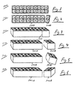
- FIG. 1-6 embodiments of the present invention utilizing a score line for separation are shown.
- an electrical connector may comprise integrally molded body portion 100, a plurality of electrical connecting elements mounted to the integrally molded body portion (inside the recesses of integrally molded body portion 100 but not separately numbered in Figs. 1-6), and score line 103 disposed on integrally molded body portion 100.
- score line 103 may permit integrally molded body portion 100 to be broken into at least two pieces, shown in this example as first piece 100A and second piece 100B.
- score line 103 may extend around the entire perimeter of integrally molded body portion 100.
- score line 103 may extend around less than the entire perimeter of integrally molded body portion 100 (e.g., along one, two or three sides).
- FIG. 7-11 embodiments of the present invention utilizing a hinge for separation are shown.
- an electrical connector may comprise integrally molded body portion 700, a plurality of electrical connecting elements mounted to the integrally molded body portion (inside the recesses of integrally molded body portion 700 but not separately numbered in Figs. 7-11), and hinge 703 disposed on integrally molded body portion 700.
- Hinge 703 may permit integrally molded body portion 700 to be broken into at least two pieces, shown in this example as first piece 700A and second piece 700B (of note, these Figs. 7-11 show hinge 703 being used to bend first piece 700A away from second piece 700B at a point in time before first piece 700A and second piece 700B become broken off from one another).
- hinge locking mechanism 707 may be utilized.
- such hinge locking mechanism 707 may compose tab 707A and tab receiver 707B.
- Tab receiver 707B may hold tab 707A such that first piece 700A and second piece 700B are held adjacent one another until such time that a user pushes tab 707A out of tab receiver 707B in order to pivot first piece 700A away from second piece 700B and break them apart.
- the break apart power connector may start with any desired number of electrical connecting elements and may be capable of being reduced to any desired number of electrical connecting elements.
- the break apart power connector may have a number of "break points" (e.g., such that a 24 pin connector may be reduced to a 22 pin connector (by removing a portion of the connector containing 2 pins), to a 20 pin connector (by removing a portion of the connector containing 4 pins) or to an 18 pin connector (by removing a portion of the connector containing 6 pins)).
- the break apart power connector may utilize "pins” (i.e., male electrical connecting elements) and/or “sockets” (i.e., female electrical connecting elements). Further still, the break apart power connector may have any desired "footprint” (e.g.. layout of electrical connecting elements) and any desired configuration (e.g., any combination of male and/or female electrical connecting elements). Further still, any desired pottion(s) may be separated by being twisted or bent off at one or more score lines and/or hinged areas. Further still, the present invention may be used, for example, with an AC-DC power supply or with any other desired type of power supply. Further still, the integrally molded body portion may comprise plastic. Further still, any steps described herein may be carried out in any desired order (and any desired steps may be added and/or deleted).
Landscapes
- Engineering & Computer Science (AREA)
- Manufacturing & Machinery (AREA)
- Connector Housings Or Holding Contact Members (AREA)
- Details Of Connecting Devices For Male And Female Coupling (AREA)
Applications Claiming Priority (1)
| Application Number | Priority Date | Filing Date | Title |
|---|---|---|---|
| US78279006P | 2006-03-16 | 2006-03-16 |
Publications (2)
| Publication Number | Publication Date |
|---|---|
| EP1835571A2 true EP1835571A2 (de) | 2007-09-19 |
| EP1835571A3 EP1835571A3 (de) | 2010-12-01 |
Family
ID=38055222
Family Applications (1)
| Application Number | Title | Priority Date | Filing Date |
|---|---|---|---|
| EP07104306A Withdrawn EP1835571A3 (de) | 2006-03-16 | 2007-03-16 | Abbrechbarer Leistungsverbinder |
Country Status (4)
| Country | Link |
|---|---|
| US (2) | US7425154B2 (de) |
| EP (1) | EP1835571A3 (de) |
| CN (1) | CN101136522B (de) |
| TW (1) | TW200818627A (de) |
Cited By (2)
| Publication number | Priority date | Publication date | Assignee | Title |
|---|---|---|---|---|
| ITMI20081531A1 (it) * | 2008-08-21 | 2010-02-22 | Gewiss Spa | Struttura di illuminazione da incasso |
| KR20190088903A (ko) * | 2018-01-19 | 2019-07-29 | 주식회사 엘지화학 | 분리형 고전압 커넥터 어셈블리 및 그 제조 방법 |
Families Citing this family (4)
| Publication number | Priority date | Publication date | Assignee | Title |
|---|---|---|---|---|
| US7491095B1 (en) * | 2008-02-25 | 2009-02-17 | Enermax Technology Corporation | Power supply socket device |
| TWI506407B (zh) * | 2009-12-30 | 2015-11-01 | Portwell Inc | 微型電源供應模組 |
| US8677861B2 (en) * | 2011-03-31 | 2014-03-25 | Corning Cable Systems Llc | Bladeless stripping device |
| US10784631B2 (en) * | 2017-01-30 | 2020-09-22 | Fci Usa Llc | Multi-piece power connector with cable pass through |
Family Cites Families (12)
| Publication number | Priority date | Publication date | Assignee | Title |
|---|---|---|---|---|
| US4230387A (en) * | 1979-04-18 | 1980-10-28 | General Staple Company, Inc. | Continuous connector |
| JPS59184476U (ja) * | 1983-05-25 | 1984-12-07 | 住友電装株式会社 | コネクタハウジング |
| US4767353A (en) * | 1983-08-29 | 1988-08-30 | Amp Incorporated | Two part connector housings in strip form |
| JPS60101356A (ja) * | 1983-11-09 | 1985-06-05 | Nissan Motor Co Ltd | 車両用自動変速機のロツクアツプ制御装置 |
| US5194018A (en) * | 1992-01-22 | 1993-03-16 | Molex Incorporated | Electrical connector assembly and method of fabricating same |
| JP2518968Y2 (ja) | 1992-02-06 | 1996-12-04 | 矢崎総業株式会社 | 合体式コネクタ |
| DE4308171A1 (de) * | 1993-03-15 | 1994-09-22 | Grote & Hartmann | Elektrische Verteilervorrichtung mit mehrteiligem Gehäuse |
| US5478243A (en) * | 1994-05-06 | 1995-12-26 | Hopkins Manufacturing Corporation | Automotive electrical wiring connector and method of installing same through small openings |
| JP3286177B2 (ja) * | 1996-08-30 | 2002-05-27 | 矢崎総業株式会社 | 圧接コネクタ |
| CN1088271C (zh) * | 1997-11-19 | 2002-07-24 | 鸿海精密工业股份有限公司 | 插头连接器 |
| CN2439125Y (zh) * | 2000-08-22 | 2001-07-11 | 宝安区松岗三辉电线厂 | 三极电源插头 |
| US6935902B1 (en) * | 2004-08-05 | 2005-08-30 | Ching Lin Chou | Coupler device for power supply facility |
-
2007
- 2007-03-14 US US11/686,127 patent/US7425154B2/en not_active Expired - Fee Related
- 2007-03-16 TW TW096109117A patent/TW200818627A/zh unknown
- 2007-03-16 EP EP07104306A patent/EP1835571A3/de not_active Withdrawn
- 2007-03-16 CN CN2007101388211A patent/CN101136522B/zh not_active Expired - Fee Related
-
2008
- 2008-08-11 US US12/189,303 patent/US20090029569A1/en not_active Abandoned
Cited By (5)
| Publication number | Priority date | Publication date | Assignee | Title |
|---|---|---|---|---|
| ITMI20081531A1 (it) * | 2008-08-21 | 2010-02-22 | Gewiss Spa | Struttura di illuminazione da incasso |
| KR20190088903A (ko) * | 2018-01-19 | 2019-07-29 | 주식회사 엘지화학 | 분리형 고전압 커넥터 어셈블리 및 그 제조 방법 |
| EP3629427A4 (de) * | 2018-01-19 | 2020-07-22 | Lg Chem, Ltd. | Trennbare hochspannungsverbinderbaugruppe und herstellungsverfahren dafür |
| US11527852B2 (en) | 2018-01-19 | 2022-12-13 | Lg Energy Solution, Ltd. | Separable high-voltage connector assembly and manufacturing method therefor |
| KR102744509B1 (ko) | 2018-01-19 | 2024-12-19 | 주식회사 엘지에너지솔루션 | 분리형 고전압 커넥터 어셈블리 및 그 제조 방법 |
Also Published As
| Publication number | Publication date |
|---|---|
| CN101136522A (zh) | 2008-03-05 |
| US20070224846A1 (en) | 2007-09-27 |
| US20090029569A1 (en) | 2009-01-29 |
| CN101136522B (zh) | 2011-12-14 |
| EP1835571A3 (de) | 2010-12-01 |
| TW200818627A (en) | 2008-04-16 |
| US7425154B2 (en) | 2008-09-16 |
Similar Documents
| Publication | Publication Date | Title |
|---|---|---|
| EP1835571A2 (de) | Abbrechbarer Leistungsverbinder | |
| US7789711B2 (en) | Rotatable electrical interconnection device | |
| US7857654B2 (en) | Plug retention device | |
| US20100009574A1 (en) | Rotatable electrical interconnection device | |
| ES3023039T3 (en) | Apparatus for retaining a plug in a receptacle | |
| US6430053B1 (en) | Pluggable transceiver module having rotatable release and removal lever with living hinge | |
| EP0886219A2 (de) | Rechnerserversystem mit drahtlosen und redundanten Adapterkarten auf einer Eingang/Ausgangkarte | |
| KR101402807B1 (ko) | 멀티 커넥터와, 그를 갖는 충전 케이블 및 데이터 케이블 | |
| US7364473B2 (en) | Connector for electronic device | |
| TW201039243A (en) | Storage device having separable type multiple-in-one connector | |
| BR0300446A (pt) | Conjunto de conector elétrico | |
| WO2006012301A3 (en) | Connector system for optical wave guides | |
| US9246269B2 (en) | Connector with a guiding portion | |
| EP2600472B1 (de) | USB-Anschluss | |
| EP1535365B1 (de) | Verbesserter steckverbindungszusammenbau mit rückwirkender kompatibilität | |
| EP2070166A1 (de) | Verbindervorrichtung | |
| TW200721611A (en) | Connector | |
| US7695316B2 (en) | Electrical connector assembly | |
| US8029306B2 (en) | Plug module | |
| JP3162616U (ja) | 複合コネクタプラグ | |
| KR200399441Y1 (ko) | 멀티 usb 젠더 | |
| US20070072491A1 (en) | Integrated signal connecting port | |
| US7335048B1 (en) | Electrical connector having latching mechanism | |
| KR200428014Y1 (ko) | 접촉식 콘넥터 | |
| KR101639330B1 (ko) | 포터블 전자기기용 케이스 |
Legal Events
| Date | Code | Title | Description |
|---|---|---|---|
| PUAI | Public reference made under article 153(3) epc to a published international application that has entered the european phase |
Free format text: ORIGINAL CODE: 0009012 |
|
| AK | Designated contracting states |
Kind code of ref document: A2 Designated state(s): AT BE BG CH CY CZ DE DK EE ES FI FR GB GR HU IE IS IT LI LT LU LV MC MT NL PL PT RO SE SI SK TR |
|
| AX | Request for extension of the european patent |
Extension state: AL BA HR MK YU |
|
| PUAL | Search report despatched |
Free format text: ORIGINAL CODE: 0009013 |
|
| AK | Designated contracting states |
Kind code of ref document: A3 Designated state(s): AT BE BG CH CY CZ DE DK EE ES FI FR GB GR HU IE IS IT LI LT LU LV MC MT NL PL PT RO SE SI SK TR |
|
| AX | Request for extension of the european patent |
Extension state: AL BA HR MK RS |
|
| RIC1 | Information provided on ipc code assigned before grant |
Ipc: H01R 13/50 20060101ALI20101022BHEP Ipc: H01R 13/514 20060101AFI20070531BHEP |
|
| AKY | No designation fees paid | ||
| REG | Reference to a national code |
Ref country code: DE Ref legal event code: R108 Effective date: 20110811 |
|
| STAA | Information on the status of an ep patent application or granted ep patent |
Free format text: STATUS: THE APPLICATION IS DEEMED TO BE WITHDRAWN |
|
| 18D | Application deemed to be withdrawn |
Effective date: 20110602 |