EP1835239A2 - Dispositif de clapet de recul - Google Patents
Dispositif de clapet de recul Download PDFInfo
- Publication number
- EP1835239A2 EP1835239A2 EP07004396A EP07004396A EP1835239A2 EP 1835239 A2 EP1835239 A2 EP 1835239A2 EP 07004396 A EP07004396 A EP 07004396A EP 07004396 A EP07004396 A EP 07004396A EP 1835239 A2 EP1835239 A2 EP 1835239A2
- Authority
- EP
- European Patent Office
- Prior art keywords
- valve device
- check valve
- flap
- stop
- flap edge
- Prior art date
- Legal status (The legal status is an assumption and is not a legal conclusion. Google has not performed a legal analysis and makes no representation as to the accuracy of the status listed.)
- Granted
Links
Images


Classifications
-
- F—MECHANICAL ENGINEERING; LIGHTING; HEATING; WEAPONS; BLASTING
- F24—HEATING; RANGES; VENTILATING
- F24F—AIR-CONDITIONING; AIR-HUMIDIFICATION; VENTILATION; USE OF AIR CURRENTS FOR SCREENING
- F24F13/00—Details common to, or for air-conditioning, air-humidification, ventilation or use of air currents for screening
- F24F13/08—Air-flow control members, e.g. louvres, grilles, flaps or guide plates
- F24F13/10—Air-flow control members, e.g. louvres, grilles, flaps or guide plates movable, e.g. dampers
- F24F13/14—Air-flow control members, e.g. louvres, grilles, flaps or guide plates movable, e.g. dampers built up of tilting members, e.g. louvre
-
- F—MECHANICAL ENGINEERING; LIGHTING; HEATING; WEAPONS; BLASTING
- F04—POSITIVE - DISPLACEMENT MACHINES FOR LIQUIDS; PUMPS FOR LIQUIDS OR ELASTIC FLUIDS
- F04D—NON-POSITIVE-DISPLACEMENT PUMPS
- F04D25/00—Pumping installations or systems
- F04D25/02—Units comprising pumps and their driving means
- F04D25/08—Units comprising pumps and their driving means the working fluid being air, e.g. for ventilation
- F04D25/12—Units comprising pumps and their driving means the working fluid being air, e.g. for ventilation the unit being adapted for mounting in apertures
- F04D25/14—Units comprising pumps and their driving means the working fluid being air, e.g. for ventilation the unit being adapted for mounting in apertures and having shutters, e.g. automatically closed when not in use
-
- F—MECHANICAL ENGINEERING; LIGHTING; HEATING; WEAPONS; BLASTING
- F04—POSITIVE - DISPLACEMENT MACHINES FOR LIQUIDS; PUMPS FOR LIQUIDS OR ELASTIC FLUIDS
- F04D—NON-POSITIVE-DISPLACEMENT PUMPS
- F04D19/00—Axial-flow pumps
- F04D19/002—Axial flow fans
-
- F—MECHANICAL ENGINEERING; LIGHTING; HEATING; WEAPONS; BLASTING
- F16—ENGINEERING ELEMENTS AND UNITS; GENERAL MEASURES FOR PRODUCING AND MAINTAINING EFFECTIVE FUNCTIONING OF MACHINES OR INSTALLATIONS; THERMAL INSULATION IN GENERAL
- F16K—VALVES; TAPS; COCKS; ACTUATING-FLOATS; DEVICES FOR VENTING OR AERATING
- F16K15/00—Check valves
- F16K15/02—Check valves with guided rigid valve members
- F16K15/03—Check valves with guided rigid valve members with a hinged closure member or with a pivoted closure member
- F16K15/035—Check valves with guided rigid valve members with a hinged closure member or with a pivoted closure member with a plurality of valve members
- F16K15/036—Dual valve members with hinges crossing the flow line substantially diametrical
- F16K15/038—Dual valve members with hinges crossing the flow line substantially diametrical having a common hinge
-
- F—MECHANICAL ENGINEERING; LIGHTING; HEATING; WEAPONS; BLASTING
- F24—HEATING; RANGES; VENTILATING
- F24F—AIR-CONDITIONING; AIR-HUMIDIFICATION; VENTILATION; USE OF AIR CURRENTS FOR SCREENING
- F24F13/00—Details common to, or for air-conditioning, air-humidification, ventilation or use of air currents for screening
- F24F13/08—Air-flow control members, e.g. louvres, grilles, flaps or guide plates
- F24F13/10—Air-flow control members, e.g. louvres, grilles, flaps or guide plates movable, e.g. dampers
- F24F13/14—Air-flow control members, e.g. louvres, grilles, flaps or guide plates movable, e.g. dampers built up of tilting members, e.g. louvre
- F24F13/1413—Air-flow control members, e.g. louvres, grilles, flaps or guide plates movable, e.g. dampers built up of tilting members, e.g. louvre using more than one tilting member, e.g. with several pivoting blades
-
- F—MECHANICAL ENGINEERING; LIGHTING; HEATING; WEAPONS; BLASTING
- F24—HEATING; RANGES; VENTILATING
- F24F—AIR-CONDITIONING; AIR-HUMIDIFICATION; VENTILATION; USE OF AIR CURRENTS FOR SCREENING
- F24F13/00—Details common to, or for air-conditioning, air-humidification, ventilation or use of air currents for screening
- F24F13/08—Air-flow control members, e.g. louvres, grilles, flaps or guide plates
- F24F13/10—Air-flow control members, e.g. louvres, grilles, flaps or guide plates movable, e.g. dampers
- F24F13/14—Air-flow control members, e.g. louvres, grilles, flaps or guide plates movable, e.g. dampers built up of tilting members, e.g. louvre
- F24F13/1426—Air-flow control members, e.g. louvres, grilles, flaps or guide plates movable, e.g. dampers built up of tilting members, e.g. louvre characterised by actuating means
Definitions
- the invention relates to a non-return valve device for closing an airway, with at least one butterfly valve, which is opened by a flowing in the air flow against a closing force.
- Such check valves are known in wall-mounted fans.
- An airway forming connecting piece is provided with a non-return valve, which is urged by a spring in the closed position. If the fan is put into operation, the air flow causes the butterfly valve to open against the spring force. When the fan is switched off, the butterfly valve closes due to the spring force. If an overpressure occurs, for example due to a wind load on a ventilation pipe system, to which the above-mentioned fan is connected, then the non-return valve is closed by the overpressure, thereby avoiding a backflowing airflow.
- the butterfly valve of the known device sets in the closed position with its peripheral edge region against a sealing surface of the airway. Due to the surface contact may cause malfunction, such as a sticking of the flap edge, so that the function of the butterfly valve is no longer guaranteed. In particular, with contaminated air streams with foreign substances due to contamination to the mentioned effect.
- the invention has for its object to provide a check valve device of the type mentioned, the functionally reliable, safe and sufficiently tight closes and even at heavy duty is easy to move and always opens reliably.
- the butterfly valve has a flap edge, the -in the closed position of the butterfly valve opposite a closing surface of the air with clearance and that at least one closing position defining stop device is provided whose extension in the direction of the course of the flap edge smaller, in particular much smaller than the length of the flap edge.
- the butterfly valve In the closed position, the butterfly valve accordingly does not contact the airway, but keeps to this one distance, namely the mentioned game, a.
- This game is chosen sufficiently small, which despite the gap resulting from the game is sufficient, not impairing the functions sealing effect. Due to the non-contact butterfly valve, sticking, jamming and so on can not occur, ie the butterfly valve can be moved smoothly and must always be opened with very little force.
- the stop device In order to define the closed position, the stop device is provided, that is, in a defined zone, the butterfly valve with an element lays against an element of the airway, the surface and / or length of the superimposed elements is very small, so it does not Malfunctions, for example by gluing or the like, comes. It is possible, for example, to form a point support which may contain one or more point contacts or only a short line support. It is essential that the length of the flap edge is substantially greater than the length of the support, so that there is only in a very small zone -in comparison to the Klappenrand- a contiguous parts in the closed position of the butterfly valve.
- the closing surface of the air path is a substantially radial closing surface. Additionally or alternatively it can be provided that the closing surface of the air path is a substantially axial closing surface.
- the flap edge is designed in particular as a radial flap edge. Additionally or alternatively, it may be provided that the flap edge is designed as an axial flap edge. Consequently, in the closed position, the radial closing surface of the airway and the radial flap edge are opposed with little play. The remaining gap is sufficiently small, so that a sealing function is ensured.
- the axial closing surface of the airway is the game against the axial flap edge, so that thereby the seal is created.
- both the mentioned radial and axial members are opposed to each other, thereby forming an angular gap which accordingly implements a labyrinth seal.
- the radial flap edge may enclose an angle ⁇ with the axial flap edge.
- the angle ⁇ is in particular 90 °, but may also differ from the squareness.
- the radial closing surface with the axial closing surface encloses an angle ⁇ , which is preferably also 90 °, but may also deviate from the squareness.
- the angle ⁇ is as large or about the same size as the angle ⁇ formed, whereby in the closed position of the butterfly valve, a uniformly dimensioned angular gap is realized.
- stop device on a wall of the airway has a stop and on the butterfly valve in the closed position against the stop passing counter-attack.
- Stop and counter stop are relatively small dimensions, whereby the stop effect is not impaired, gluing or tilting and so on is avoided.
- Stop and counter stop preferably occur substantially axially on each other. If in the course of this application is spoken by an axial direction, this corresponds essentially to the direction of the air flow in the airway.
- radial direction is meant a direction from the center of the airway radially outward. If the airway is circular in cross-section, the radial direction points radially outward from the circle center (360 °).
- the at least one butterfly valve to the vertical is arranged so inclined pivotally mounted that a weight force component of its weight generates the closing force. Due to the inclination of the butterfly valve relative to the vertical, it tends accordingly to fall, because its weight, that is, the resulting weight force, is decomposed into a component acting in the closing direction of the butterfly valve. Additional closing elements, such as the closing springs mentioned in the prior art, are therefore not required.
- the butterfly valve has at least one additional weight for increasing the weight force component.
- This additional weight is located in particular in the area of the flap edge. It may be formed by a thickened flap edge, for example by material accumulation and / or additional weights. With an accumulation of material and / or additional weights, a stiffening effect is also achieved and, provided that the flap edge is correspondingly enlarged in its surface, a larger sealing surface is also formed, which leads to an improved sealing function.
- the maximum opening position of the butterfly valve is preferably defined by applying a flap stop the butterfly valve to a flap counter-attack of the airway. In the maximum open position, only flap stop and flap counter-stop contact each other, these two elements are also designed to be very small in terms of their contact, whereby a smooth running is guaranteed and maintained.
- the opening angle ⁇ in the maximum opening position of the butterfly valve is less than 90 °, preferably about 60 to 80 °, in particular 75 °.
- the opening angle ⁇ is formed between the closed position and the maximum open position of the shut-off flap.
- the invention there are two butterfly valves whose pivot axes are adjacent and preferably parallel to each other.
- the two pivot axes are each at a side edge of the associated butterfly valve, the remaining free edge zones of the butterfly valve form the already mentioned flap edge.
- the swivel axes having side edges of the two butterfly valves are so close to each other that only a minimum gap is formed between them.
- the two butterfly valves each have an approximately semicircular, the flap edge forming contour area and together close the approximately circular in cross-section airway.
- the two butterfly valves are preferably identical. They are fully symmetrical. They are rotated 180 degrees relative to each other as the one flap opens clockwise and the other flap counterclockwise, i.e., their two pivot axes are parallel to one another. In the region of the two pivot axes, the two butterfly valves in the closed position border on each other so closely that they touch, almost touch and / or overlap slightly so that they close tightly or almost tightly.
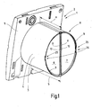
- FIG. 1 shows an air-conditioning device 1, which is designed as a wall-mounted ventilator 2.
- the built-in wall fan 2 has an air duct connecting piece 3, which forms an airway 4.
- an electric drive motor is arranged with a fan wheel, wherein the fan during operation sucks air through an air inlet of a wall cover 5 and promotes via the air duct connection piece 3 in an exhaust duct connected thereto or the like.
- the air connection piece 3 which also forms a motor housing for a fan provided with electric motor (not shown), there are two butterfly valves 6 and 7, which together with the air path 4 form a check valve device 8.
- the two butterfly valves 6 and 7, which are located at the free end of the air connection piece 3, each have an approximately semicircular whyumriss Scheme 9 and a rectilinear outer contour portion 10, wherein in the illustrated in Figure 1 closed position of the two butterfly valves 6 and 7 together this approximately Close circular airway 4 in cross-section.
- the two shut-off flaps 6 and 7 have in the region (in particular in extension) of their rectilinear outer contour regions 10 each pivot axes 11 so that they-as apparent from the figure 2 in operation of the wall installation fan 2 by the subsidized Swing airflow to maximum open position and therefore release airway 4. If a sufficiently large counter-pressure builds up in the exhaust air duct when the wall-mounted ventilator 2 is switched off or switched on, then it is sealed off by closing the shut-off flaps 6 and 7 (FIG. 1), so that no air backflow can take place. From the figure 1 it can be seen that the two butterfly valves 6 and 7 are arranged obliquely with respect to the horizontal direction.
- the angle to the horizontal is about 6 to 45 °, in particular 8 to 25 °, preferably about 8.5 °. It is effected by the fact that the air duct connection piece 3 has the dimension a in the upper region and the dimension b in the lower region, a being shorter than b. This has the consequence that each of the two butterfly valves 6, 7 is closed with a wall mounted fan by a weight force component of their respective weight, ie, the respective weight force component generates a closing force on the corresponding butterfly valve 6, 7, so no additional closing means, such as springs or the like, are required.
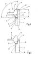
- the shut-off flap 6 has a flap edge 12 which forms the outer contour region 9.
- the flap edge 12 is opposite to a closing surface 14 of the air path 4 according to FIG. From this figure 4 it can be seen that the damper blade 13 in the thickened flap edge 12 on both sides via inclined surfaces 15 merges, so that a relatively wider (dimension c) radial flap edge 16 is formed.
- the flap edge 12 further includes an axial flap edge 17, the radial flap edge 16 enclosing the axial flap edge 17 at an angle ⁇ which is 90 °.
- the air path 4 which is circular in shape, has on its wall 18 inside an annular stepped recess 19, which causes the closing surface 14 has a radial closing surface 20 and an axial closing surface 21.
- the radial closing surface 20 encloses with the axial closing surface 21 at an angle ⁇ , which is 90 °.
- a stop device 26 which defines the closed position of the butterfly valve 6.
- the wall 18 of the air path 4 is provided with an open-edged recess 27, wherein the recess base 28 forms a stop 29.
- the stopper 29 is located at a height level (in the axial direction) that it faces the shut-off valve 6 in the closed position.
- FIG. 5 shows a radial section through the stop device 26 of the shut-off flap 6 located in the closed position.
- the level of the stop 29 is-seen in the axial direction-at a distance from the axial closing surface 21, such that also in the region of the stop device 26 of the axial gap 23 and a (reduced) portion of the radial gap 22 is formed.
- a pointing in the radial direction counter-stop 30 which abuts against the stop 29 in the closed position of the butterfly valve 6 axially.
- the counterstop 30 is composed of three radial stubs 31, which are connected to one another via web walls 32. Accordingly, there is a three-point support in the stop device 26, namely placing the shell walls of the three radial webs 31 on the flat surface of the stopper 29th
- FIG 7 is a plan view of the butterfly valve 6 is shown.
- the thickened flap edge 12 and the counter-stop 30 can be seen.
- two axle stubs 33 can be seen, which are connected via a rim zone thickening 35, which extends adjacent to the outer contour region 10 over its entire length.
- the edge zone thickening 35 ensures mechanical stability. It is not located directly on the outer contour portion 10, but slightly spaced thereto, since the outer contour portion 10 is formed by a flap edge strip 40, which ensures optimum sealing in the closed position of the butterfly valves 6, 7.
- the diameter of the two axle stubs 33 are the same size.
- the Offenwolf 36 has a projection 37 which in the open position of the butterfly valve 6 on a flap counter abutment 46 forming end wall 38 of the wall 18 of the air path 4 line-like or point-like touches and prevents further opening movement in this way.
- the end wall 38 extends in the direction of the longitudinal extent of the air duct connecting piece 3.
- the opening angle ⁇ is ⁇ 90 ° ( Figure 6A) is formed. It is preferably 75 °.
- the respective open position stop 36 is located with its projection 37 in each case one edge receiving recess 39 of the wall 18 of the air path 4 without contact.
- the axle stub 33 is inserted at the onset of the butterfly valve 6 in a bearing bore 41 of the wall 18.
- the opposite axle stub 33 is inserted into a corresponding bearing bore 41 of the wall 18.
- the butterfly valve 6 is bent elastically; after inserting it springs back into its flat starting position. The same applies to the insertion of the two axle stub 34 of the butterfly valve 7 in bearing bore 42nd
- Figures 8 and 9 show a rear view of the ventilation device 1, wherein in the figure 8, the wall installation of the wall installation fan 4 is not aligned in the horizontal and vertical direction is done accurately, but a slated installation, namely inclined in the counterclockwise direction, is present. Accordingly, Figure 9 shows a non-desired mounting position, which is rotated clockwise by an angle. If the twist angle does not exceed about 4 ° counterclockwise or clockwise, the function of the flaps 6 and 7 is nevertheless given with regard to their self-closing by weight.
- the check valve device according to the invention is suitable both for wall mounting -as already described as well as for the ceiling installation.
- the minimum pressure for opening up to maximum open position is approximately 2 to 3 Pa.
- the arrangement of the two butterfly valves 6 and 7 is chosen such that they do not touch each other in their open positions.
- the two butterfly valves 6 and 7 are identical, so that a simple production and non-interchangeable assembly is possible. By the game between the flap edges and the closing surfaces increased friction or blocking is avoided. Even dirt such as dust, hair spray and so on do not lead to a malfunction.
- the check valve device according to the invention consists of metal and / or plastic, preferably entirely made of plastic.
Landscapes
- Engineering & Computer Science (AREA)
- General Engineering & Computer Science (AREA)
- Mechanical Engineering (AREA)
- Chemical & Material Sciences (AREA)
- Combustion & Propulsion (AREA)
- Lift Valve (AREA)
- Air-Flow Control Members (AREA)
- Check Valves (AREA)
Applications Claiming Priority (1)
| Application Number | Priority Date | Filing Date | Title |
|---|---|---|---|
| DE202006004839U DE202006004839U1 (de) | 2006-03-15 | 2006-03-15 | Rückschlagklappenvorrichtung |
Publications (3)
| Publication Number | Publication Date |
|---|---|
| EP1835239A2 true EP1835239A2 (fr) | 2007-09-19 |
| EP1835239A3 EP1835239A3 (fr) | 2009-10-28 |
| EP1835239B1 EP1835239B1 (fr) | 2014-09-17 |
Family
ID=36686863
Family Applications (1)
| Application Number | Title | Priority Date | Filing Date |
|---|---|---|---|
| EP07004396.3A Active EP1835239B1 (fr) | 2006-03-15 | 2007-03-03 | Dispositif de clapet de recul |
Country Status (3)
| Country | Link |
|---|---|
| EP (1) | EP1835239B1 (fr) |
| KR (1) | KR20070093875A (fr) |
| DE (1) | DE202006004839U1 (fr) |
Cited By (2)
| Publication number | Priority date | Publication date | Assignee | Title |
|---|---|---|---|---|
| US20160178233A1 (en) * | 2014-12-22 | 2016-06-23 | Indesit Company S.P.A. | Extraction hood |
| US11231049B2 (en) | 2018-02-02 | 2022-01-25 | Novenco Building & Industry A/S | Blower and a blower diffuser |
Families Citing this family (4)
| Publication number | Priority date | Publication date | Assignee | Title |
|---|---|---|---|---|
| DE102008028613A1 (de) * | 2008-06-18 | 2009-12-24 | Pluggit International B.V. | T-förmiges Abzweigstück, insbesondere für ein Lüftungssystem |
| US9605868B2 (en) | 2013-03-14 | 2017-03-28 | Mitek Holdings, Inc. | Fan array backflow preventer |
| DE102014113210A1 (de) * | 2014-09-12 | 2016-03-17 | Naber Holding Gmbh & Co. Kg | Verschlussanordnung für einen Luftkanal und eine entsprechende Gebäudeanordnung |
| US9803761B1 (en) * | 2016-04-12 | 2017-10-31 | Hs Wroclaw Sp. Z.O.O. | Flapper check valve bumper |
Family Cites Families (5)
| Publication number | Priority date | Publication date | Assignee | Title |
|---|---|---|---|---|
| US3009475A (en) * | 1959-09-14 | 1961-11-21 | Wm Cissell Mfg Company | Damper assembly |
| US4094336A (en) * | 1977-04-19 | 1978-06-13 | Urschel John N | Back draft for exhaust fans and hoods |
| IT233463Y1 (it) * | 1994-06-02 | 2000-01-28 | Vortice Elettrosociali Spa | Serranda di non ritorno a bassa perdita di carico per apparecchi di ventilazione in genere |
| FR2770411B1 (fr) * | 1997-10-30 | 2000-01-21 | Strulik Sa | Clapet pare-feu pour conduit d'aeration |
| DE10245403B3 (de) * | 2002-09-28 | 2004-04-22 | Miele & Cie. Kg | Rückstauklappe zur Anordnung in einem Abluftweg, insbesondere einer Dunstabzugsvorrichtung |
-
2006
- 2006-03-15 DE DE202006004839U patent/DE202006004839U1/de not_active Expired - Lifetime
-
2007
- 2007-03-03 EP EP07004396.3A patent/EP1835239B1/fr active Active
- 2007-03-14 KR KR1020070024756A patent/KR20070093875A/ko not_active Withdrawn
Cited By (4)
| Publication number | Priority date | Publication date | Assignee | Title |
|---|---|---|---|---|
| US20160178233A1 (en) * | 2014-12-22 | 2016-06-23 | Indesit Company S.P.A. | Extraction hood |
| US10551085B2 (en) * | 2014-12-22 | 2020-02-04 | Whirlpool Corporation | Extraction hood |
| US11692734B2 (en) | 2014-12-22 | 2023-07-04 | Whirlpool Corporation | Extraction hood |
| US11231049B2 (en) | 2018-02-02 | 2022-01-25 | Novenco Building & Industry A/S | Blower and a blower diffuser |
Also Published As
| Publication number | Publication date |
|---|---|
| DE202006004839U1 (de) | 2006-06-29 |
| EP1835239B1 (fr) | 2014-09-17 |
| EP1835239A3 (fr) | 2009-10-28 |
| KR20070093875A (ko) | 2007-09-19 |
Similar Documents
| Publication | Publication Date | Title |
|---|---|---|
| EP1835238B1 (fr) | Canal d'air équipé d'un clapet de recul activé par gravitation | |
| EP1939456B1 (fr) | Dispositif de passage d'air | |
| EP1835239B1 (fr) | Dispositif de clapet de recul | |
| DE102011106744B3 (de) | Ventilvorrichtung zur Regelung eines Abgasstroms einer Verbrennungskraftmaschine | |
| EP2037792B1 (fr) | Vanne à air additionnel | |
| DE102009056682A1 (de) | Lüfter | |
| DE4228866A1 (de) | Absperrvorrichtung, insbesondere für eine Heizungs- oder Klimaanlage eines Kraftfahrzeugs | |
| WO2005108835A1 (fr) | Ensemble soupape monte dans un reniflard de carter de vilebrequin | |
| DE102017120003A1 (de) | Luftausströmer für ein Fahrzeug | |
| DE19936457A1 (de) | Drosseleinrichtung mit einer Klappe zum Einbau in eine Flanschverbindung | |
| EP0655587A2 (fr) | Dispositif d'apport d'air | |
| DE19959109B4 (de) | Drehklappenventil | |
| DE19512874B4 (de) | Drosselklappenstutzen | |
| WO2014095403A1 (fr) | Soupape | |
| DE10155940A1 (de) | Klappe zur Verwendung in Rauchgas- oder Luftkanälen | |
| WO2002055914A1 (fr) | Soupape a clapet | |
| DE3025109C2 (de) | In eine ein gasförmiges Medium führende Leitung einsetzbare Rückschlagklappe aus Kunststoff (Polystyrol), insbesondere für Lüftungsanlagen | |
| DE202004001919U1 (de) | Absperrvorrichtung für ein Gas führendes Rohr | |
| DE102004032974A1 (de) | Klappenventil für die Abgasanlage eines Kraftfahrzeugs | |
| EP0798517A2 (fr) | Ventilateur de toit | |
| EP1811137A2 (fr) | Dispositif de rotation de soupape | |
| EP4279146B1 (fr) | Clapet coupe-feu | |
| EP2565549B1 (fr) | Dispositif de réglage d'un débit volumétrique d'air | |
| DE102010060837A1 (de) | Luftklappenvorrichtung für eine lufttechnische Einrichtung | |
| DE202017102388U1 (de) | Regelklappe und Adapter für eine Regelklappe |
Legal Events
| Date | Code | Title | Description |
|---|---|---|---|
| PUAI | Public reference made under article 153(3) epc to a published international application that has entered the european phase |
Free format text: ORIGINAL CODE: 0009012 |
|
| AK | Designated contracting states |
Kind code of ref document: A2 Designated state(s): AT BE BG CH CY CZ DE DK EE ES FI FR GB GR HU IE IS IT LI LT LU LV MC MT NL PL PT RO SE SI SK TR |
|
| AX | Request for extension of the european patent |
Extension state: AL BA HR MK YU |
|
| PUAL | Search report despatched |
Free format text: ORIGINAL CODE: 0009013 |
|
| AK | Designated contracting states |
Kind code of ref document: A3 Designated state(s): AT BE BG CH CY CZ DE DK EE ES FI FR GB GR HU IE IS IT LI LT LU LV MC MT NL PL PT RO SE SI SK TR |
|
| AX | Request for extension of the european patent |
Extension state: AL BA HR MK RS |
|
| RIC1 | Information provided on ipc code assigned before grant |
Ipc: F04D 25/14 20060101ALI20090921BHEP Ipc: F24F 13/14 20060101AFI20070605BHEP |
|
| 17P | Request for examination filed |
Effective date: 20100304 |
|
| AKX | Designation fees paid |
Designated state(s): AT BE BG CH CY CZ DE DK EE ES FI FR GB GR HU IE IS IT LI LT LU LV MC MT NL PL PT RO SE SI SK TR |
|
| REG | Reference to a national code |
Ref country code: DE Ref legal event code: R079 Ref document number: 502007013458 Country of ref document: DE Free format text: PREVIOUS MAIN CLASS: F24F0013140000 Ipc: F16K0015020000 |
|
| GRAP | Despatch of communication of intention to grant a patent |
Free format text: ORIGINAL CODE: EPIDOSNIGR1 |
|
| RIC1 | Information provided on ipc code assigned before grant |
Ipc: F16K 15/02 20060101AFI20140114BHEP Ipc: F04D 19/00 20060101ALI20140114BHEP |
|
| INTG | Intention to grant announced |
Effective date: 20140217 |
|
| GRAP | Despatch of communication of intention to grant a patent |
Free format text: ORIGINAL CODE: EPIDOSNIGR1 |
|
| INTG | Intention to grant announced |
Effective date: 20140411 |
|
| GRAS | Grant fee paid |
Free format text: ORIGINAL CODE: EPIDOSNIGR3 |
|
| GRAA | (expected) grant |
Free format text: ORIGINAL CODE: 0009210 |
|
| AK | Designated contracting states |
Kind code of ref document: B1 Designated state(s): AT BE BG CH CY CZ DE DK EE ES FI FR GB GR HU IE IS IT LI LT LU LV MC MT NL PL PT RO SE SI SK TR |
|
| REG | Reference to a national code |
Ref country code: GB Ref legal event code: FG4D Free format text: NOT ENGLISH |
|
| REG | Reference to a national code |
Ref country code: CH Ref legal event code: EP |
|
| REG | Reference to a national code |
Ref country code: IE Ref legal event code: FG4D Free format text: LANGUAGE OF EP DOCUMENT: GERMAN |
|
| REG | Reference to a national code |
Ref country code: AT Ref legal event code: REF Ref document number: 687867 Country of ref document: AT Kind code of ref document: T Effective date: 20141015 |
|
| REG | Reference to a national code |
Ref country code: DE Ref legal event code: R096 Ref document number: 502007013458 Country of ref document: DE Effective date: 20141030 |
|
| REG | Reference to a national code |
Ref country code: CH Ref legal event code: NV Representative=s name: FREI PATENTANWALTSBUERO AG, CH |
|
| PG25 | Lapsed in a contracting state [announced via postgrant information from national office to epo] |
Ref country code: LT Free format text: LAPSE BECAUSE OF FAILURE TO SUBMIT A TRANSLATION OF THE DESCRIPTION OR TO PAY THE FEE WITHIN THE PRESCRIBED TIME-LIMIT Effective date: 20140917 Ref country code: FI Free format text: LAPSE BECAUSE OF FAILURE TO SUBMIT A TRANSLATION OF THE DESCRIPTION OR TO PAY THE FEE WITHIN THE PRESCRIBED TIME-LIMIT Effective date: 20140917 Ref country code: SE Free format text: LAPSE BECAUSE OF FAILURE TO SUBMIT A TRANSLATION OF THE DESCRIPTION OR TO PAY THE FEE WITHIN THE PRESCRIBED TIME-LIMIT Effective date: 20140917 Ref country code: GR Free format text: LAPSE BECAUSE OF FAILURE TO SUBMIT A TRANSLATION OF THE DESCRIPTION OR TO PAY THE FEE WITHIN THE PRESCRIBED TIME-LIMIT Effective date: 20141218 |
|
| REG | Reference to a national code |
Ref country code: NL Ref legal event code: VDEP Effective date: 20140917 |
|
| REG | Reference to a national code |
Ref country code: LT Ref legal event code: MG4D |
|
| PG25 | Lapsed in a contracting state [announced via postgrant information from national office to epo] |
Ref country code: LV Free format text: LAPSE BECAUSE OF FAILURE TO SUBMIT A TRANSLATION OF THE DESCRIPTION OR TO PAY THE FEE WITHIN THE PRESCRIBED TIME-LIMIT Effective date: 20140917 Ref country code: CY Free format text: LAPSE BECAUSE OF FAILURE TO SUBMIT A TRANSLATION OF THE DESCRIPTION OR TO PAY THE FEE WITHIN THE PRESCRIBED TIME-LIMIT Effective date: 20140917 |
|
| PG25 | Lapsed in a contracting state [announced via postgrant information from national office to epo] |
Ref country code: NL Free format text: LAPSE BECAUSE OF FAILURE TO SUBMIT A TRANSLATION OF THE DESCRIPTION OR TO PAY THE FEE WITHIN THE PRESCRIBED TIME-LIMIT Effective date: 20140917 |
|
| PG25 | Lapsed in a contracting state [announced via postgrant information from national office to epo] |
Ref country code: PT Free format text: LAPSE BECAUSE OF FAILURE TO SUBMIT A TRANSLATION OF THE DESCRIPTION OR TO PAY THE FEE WITHIN THE PRESCRIBED TIME-LIMIT Effective date: 20150119 Ref country code: SK Free format text: LAPSE BECAUSE OF FAILURE TO SUBMIT A TRANSLATION OF THE DESCRIPTION OR TO PAY THE FEE WITHIN THE PRESCRIBED TIME-LIMIT Effective date: 20140917 Ref country code: IS Free format text: LAPSE BECAUSE OF FAILURE TO SUBMIT A TRANSLATION OF THE DESCRIPTION OR TO PAY THE FEE WITHIN THE PRESCRIBED TIME-LIMIT Effective date: 20150117 Ref country code: EE Free format text: LAPSE BECAUSE OF FAILURE TO SUBMIT A TRANSLATION OF THE DESCRIPTION OR TO PAY THE FEE WITHIN THE PRESCRIBED TIME-LIMIT Effective date: 20140917 Ref country code: ES Free format text: LAPSE BECAUSE OF FAILURE TO SUBMIT A TRANSLATION OF THE DESCRIPTION OR TO PAY THE FEE WITHIN THE PRESCRIBED TIME-LIMIT Effective date: 20140917 Ref country code: CZ Free format text: LAPSE BECAUSE OF FAILURE TO SUBMIT A TRANSLATION OF THE DESCRIPTION OR TO PAY THE FEE WITHIN THE PRESCRIBED TIME-LIMIT Effective date: 20140917 Ref country code: RO Free format text: LAPSE BECAUSE OF FAILURE TO SUBMIT A TRANSLATION OF THE DESCRIPTION OR TO PAY THE FEE WITHIN THE PRESCRIBED TIME-LIMIT Effective date: 20140917 |
|
| PG25 | Lapsed in a contracting state [announced via postgrant information from national office to epo] |
Ref country code: PL Free format text: LAPSE BECAUSE OF FAILURE TO SUBMIT A TRANSLATION OF THE DESCRIPTION OR TO PAY THE FEE WITHIN THE PRESCRIBED TIME-LIMIT Effective date: 20140917 |
|
| REG | Reference to a national code |
Ref country code: DE Ref legal event code: R097 Ref document number: 502007013458 Country of ref document: DE |
|
| PLBE | No opposition filed within time limit |
Free format text: ORIGINAL CODE: 0009261 |
|
| STAA | Information on the status of an ep patent application or granted ep patent |
Free format text: STATUS: NO OPPOSITION FILED WITHIN TIME LIMIT |
|
| PG25 | Lapsed in a contracting state [announced via postgrant information from national office to epo] |
Ref country code: DK Free format text: LAPSE BECAUSE OF FAILURE TO SUBMIT A TRANSLATION OF THE DESCRIPTION OR TO PAY THE FEE WITHIN THE PRESCRIBED TIME-LIMIT Effective date: 20140917 |
|
| 26N | No opposition filed |
Effective date: 20150618 |
|
| PG25 | Lapsed in a contracting state [announced via postgrant information from national office to epo] |
Ref country code: IT Free format text: LAPSE BECAUSE OF FAILURE TO SUBMIT A TRANSLATION OF THE DESCRIPTION OR TO PAY THE FEE WITHIN THE PRESCRIBED TIME-LIMIT Effective date: 20140917 |
|
| PG25 | Lapsed in a contracting state [announced via postgrant information from national office to epo] |
Ref country code: MC Free format text: LAPSE BECAUSE OF FAILURE TO SUBMIT A TRANSLATION OF THE DESCRIPTION OR TO PAY THE FEE WITHIN THE PRESCRIBED TIME-LIMIT Effective date: 20140917 Ref country code: LU Free format text: LAPSE BECAUSE OF FAILURE TO SUBMIT A TRANSLATION OF THE DESCRIPTION OR TO PAY THE FEE WITHIN THE PRESCRIBED TIME-LIMIT Effective date: 20150303 |
|
| GBPC | Gb: european patent ceased through non-payment of renewal fee |
Effective date: 20150303 |
|
| PG25 | Lapsed in a contracting state [announced via postgrant information from national office to epo] |
Ref country code: SI Free format text: LAPSE BECAUSE OF FAILURE TO SUBMIT A TRANSLATION OF THE DESCRIPTION OR TO PAY THE FEE WITHIN THE PRESCRIBED TIME-LIMIT Effective date: 20140917 |
|
| REG | Reference to a national code |
Ref country code: FR Ref legal event code: ST Effective date: 20151130 |
|
| REG | Reference to a national code |
Ref country code: IE Ref legal event code: MM4A |
|
| PG25 | Lapsed in a contracting state [announced via postgrant information from national office to epo] |
Ref country code: IE Free format text: LAPSE BECAUSE OF NON-PAYMENT OF DUE FEES Effective date: 20150303 Ref country code: GB Free format text: LAPSE BECAUSE OF NON-PAYMENT OF DUE FEES Effective date: 20150303 |
|
| PG25 | Lapsed in a contracting state [announced via postgrant information from national office to epo] |
Ref country code: FR Free format text: LAPSE BECAUSE OF NON-PAYMENT OF DUE FEES Effective date: 20150331 |
|
| PG25 | Lapsed in a contracting state [announced via postgrant information from national office to epo] |
Ref country code: MT Free format text: LAPSE BECAUSE OF FAILURE TO SUBMIT A TRANSLATION OF THE DESCRIPTION OR TO PAY THE FEE WITHIN THE PRESCRIBED TIME-LIMIT Effective date: 20140917 |
|
| PG25 | Lapsed in a contracting state [announced via postgrant information from national office to epo] |
Ref country code: BG Free format text: LAPSE BECAUSE OF FAILURE TO SUBMIT A TRANSLATION OF THE DESCRIPTION OR TO PAY THE FEE WITHIN THE PRESCRIBED TIME-LIMIT Effective date: 20140917 Ref country code: HU Free format text: LAPSE BECAUSE OF FAILURE TO SUBMIT A TRANSLATION OF THE DESCRIPTION OR TO PAY THE FEE WITHIN THE PRESCRIBED TIME-LIMIT; INVALID AB INITIO Effective date: 20070303 |
|
| PG25 | Lapsed in a contracting state [announced via postgrant information from national office to epo] |
Ref country code: BE Free format text: LAPSE BECAUSE OF NON-PAYMENT OF DUE FEES Effective date: 20150331 |
|
| PG25 | Lapsed in a contracting state [announced via postgrant information from national office to epo] |
Ref country code: TR Free format text: LAPSE BECAUSE OF FAILURE TO SUBMIT A TRANSLATION OF THE DESCRIPTION OR TO PAY THE FEE WITHIN THE PRESCRIBED TIME-LIMIT Effective date: 20140917 |
|
| REG | Reference to a national code |
Ref country code: CH Ref legal event code: PCAR Free format text: NEW ADDRESS: POSTFACH, 8032 ZUERICH (CH) |
|
| PGFP | Annual fee paid to national office [announced via postgrant information from national office to epo] |
Ref country code: AT Payment date: 20240321 Year of fee payment: 18 |
|
| PGFP | Annual fee paid to national office [announced via postgrant information from national office to epo] |
Ref country code: DE Payment date: 20240326 Year of fee payment: 18 |
|
| PGFP | Annual fee paid to national office [announced via postgrant information from national office to epo] |
Ref country code: CH Payment date: 20240401 Year of fee payment: 18 |
|
| REG | Reference to a national code |
Ref country code: DE Ref legal event code: R119 Ref document number: 502007013458 Country of ref document: DE |
|
| REG | Reference to a national code |
Ref country code: CH Ref legal event code: H13 Free format text: ST27 STATUS EVENT CODE: U-0-0-H10-H13 (AS PROVIDED BY THE NATIONAL OFFICE) Effective date: 20251023 |
|
| REG | Reference to a national code |
Ref country code: AT Ref legal event code: MM01 Ref document number: 687867 Country of ref document: AT Kind code of ref document: T Effective date: 20250303 |
|
| PG25 | Lapsed in a contracting state [announced via postgrant information from national office to epo] |
Ref country code: DE Free format text: LAPSE BECAUSE OF NON-PAYMENT OF DUE FEES Effective date: 20251001 |
|
| PG25 | Lapsed in a contracting state [announced via postgrant information from national office to epo] |
Ref country code: AT Free format text: LAPSE BECAUSE OF NON-PAYMENT OF DUE FEES Effective date: 20250303 |
|
| PG25 | Lapsed in a contracting state [announced via postgrant information from national office to epo] |
Ref country code: CH Free format text: LAPSE BECAUSE OF NON-PAYMENT OF DUE FEES Effective date: 20250331 |