EP1832668A1 - Processus de réparation local de revêtements de barrière thermique dans les composants de moteur à turbine - Google Patents
Processus de réparation local de revêtements de barrière thermique dans les composants de moteur à turbine Download PDFInfo
- Publication number
- EP1832668A1 EP1832668A1 EP07102932A EP07102932A EP1832668A1 EP 1832668 A1 EP1832668 A1 EP 1832668A1 EP 07102932 A EP07102932 A EP 07102932A EP 07102932 A EP07102932 A EP 07102932A EP 1832668 A1 EP1832668 A1 EP 1832668A1
- Authority
- EP
- European Patent Office
- Prior art keywords
- thermal barrier
- barrier coating
- locally
- spalled region
- component
- Prior art date
- Legal status (The legal status is an assumption and is not a legal conclusion. Google has not performed a legal analysis and makes no representation as to the accuracy of the status listed.)
- Withdrawn
Links
Images


Classifications
-
- C—CHEMISTRY; METALLURGY
- C23—COATING METALLIC MATERIAL; COATING MATERIAL WITH METALLIC MATERIAL; CHEMICAL SURFACE TREATMENT; DIFFUSION TREATMENT OF METALLIC MATERIAL; COATING BY VACUUM EVAPORATION, BY SPUTTERING, BY ION IMPLANTATION OR BY CHEMICAL VAPOUR DEPOSITION, IN GENERAL; INHIBITING CORROSION OF METALLIC MATERIAL OR INCRUSTATION IN GENERAL
- C23C—COATING METALLIC MATERIAL; COATING MATERIAL WITH METALLIC MATERIAL; SURFACE TREATMENT OF METALLIC MATERIAL BY DIFFUSION INTO THE SURFACE, BY CHEMICAL CONVERSION OR SUBSTITUTION; COATING BY VACUUM EVAPORATION, BY SPUTTERING, BY ION IMPLANTATION OR BY CHEMICAL VAPOUR DEPOSITION, IN GENERAL
- C23C4/00—Coating by spraying the coating material in the molten state, e.g. by flame, plasma or electric discharge
- C23C4/02—Pretreatment of the material to be coated, e.g. for coating on selected surface areas
-
- C—CHEMISTRY; METALLURGY
- C23—COATING METALLIC MATERIAL; COATING MATERIAL WITH METALLIC MATERIAL; CHEMICAL SURFACE TREATMENT; DIFFUSION TREATMENT OF METALLIC MATERIAL; COATING BY VACUUM EVAPORATION, BY SPUTTERING, BY ION IMPLANTATION OR BY CHEMICAL VAPOUR DEPOSITION, IN GENERAL; INHIBITING CORROSION OF METALLIC MATERIAL OR INCRUSTATION IN GENERAL
- C23C—COATING METALLIC MATERIAL; COATING MATERIAL WITH METALLIC MATERIAL; SURFACE TREATMENT OF METALLIC MATERIAL BY DIFFUSION INTO THE SURFACE, BY CHEMICAL CONVERSION OR SUBSTITUTION; COATING BY VACUUM EVAPORATION, BY SPUTTERING, BY ION IMPLANTATION OR BY CHEMICAL VAPOUR DEPOSITION, IN GENERAL
- C23C28/00—Coating for obtaining at least two superposed coatings either by methods not provided for in a single one of groups C23C2/00 - C23C26/00 or by combinations of methods provided for in subclasses C23C and C25C or C25D
- C23C28/30—Coatings combining at least one metallic layer and at least one inorganic non-metallic layer
- C23C28/32—Coatings combining at least one metallic layer and at least one inorganic non-metallic layer including at least one pure metallic layer
- C23C28/321—Coatings combining at least one metallic layer and at least one inorganic non-metallic layer including at least one pure metallic layer with at least one metal alloy layer
- C23C28/3215—Coatings combining at least one metallic layer and at least one inorganic non-metallic layer including at least one pure metallic layer with at least one metal alloy layer at least one MCrAlX layer
-
- C—CHEMISTRY; METALLURGY
- C23—COATING METALLIC MATERIAL; COATING MATERIAL WITH METALLIC MATERIAL; CHEMICAL SURFACE TREATMENT; DIFFUSION TREATMENT OF METALLIC MATERIAL; COATING BY VACUUM EVAPORATION, BY SPUTTERING, BY ION IMPLANTATION OR BY CHEMICAL VAPOUR DEPOSITION, IN GENERAL; INHIBITING CORROSION OF METALLIC MATERIAL OR INCRUSTATION IN GENERAL
- C23C—COATING METALLIC MATERIAL; COATING MATERIAL WITH METALLIC MATERIAL; SURFACE TREATMENT OF METALLIC MATERIAL BY DIFFUSION INTO THE SURFACE, BY CHEMICAL CONVERSION OR SUBSTITUTION; COATING BY VACUUM EVAPORATION, BY SPUTTERING, BY ION IMPLANTATION OR BY CHEMICAL VAPOUR DEPOSITION, IN GENERAL
- C23C28/00—Coating for obtaining at least two superposed coatings either by methods not provided for in a single one of groups C23C2/00 - C23C26/00 or by combinations of methods provided for in subclasses C23C and C25C or C25D
- C23C28/30—Coatings combining at least one metallic layer and at least one inorganic non-metallic layer
- C23C28/32—Coatings combining at least one metallic layer and at least one inorganic non-metallic layer including at least one pure metallic layer
- C23C28/325—Coatings combining at least one metallic layer and at least one inorganic non-metallic layer including at least one pure metallic layer with layers graded in composition or in physical properties
-
- C—CHEMISTRY; METALLURGY
- C23—COATING METALLIC MATERIAL; COATING MATERIAL WITH METALLIC MATERIAL; CHEMICAL SURFACE TREATMENT; DIFFUSION TREATMENT OF METALLIC MATERIAL; COATING BY VACUUM EVAPORATION, BY SPUTTERING, BY ION IMPLANTATION OR BY CHEMICAL VAPOUR DEPOSITION, IN GENERAL; INHIBITING CORROSION OF METALLIC MATERIAL OR INCRUSTATION IN GENERAL
- C23C—COATING METALLIC MATERIAL; COATING MATERIAL WITH METALLIC MATERIAL; SURFACE TREATMENT OF METALLIC MATERIAL BY DIFFUSION INTO THE SURFACE, BY CHEMICAL CONVERSION OR SUBSTITUTION; COATING BY VACUUM EVAPORATION, BY SPUTTERING, BY ION IMPLANTATION OR BY CHEMICAL VAPOUR DEPOSITION, IN GENERAL
- C23C28/00—Coating for obtaining at least two superposed coatings either by methods not provided for in a single one of groups C23C2/00 - C23C26/00 or by combinations of methods provided for in subclasses C23C and C25C or C25D
- C23C28/30—Coatings combining at least one metallic layer and at least one inorganic non-metallic layer
- C23C28/34—Coatings combining at least one metallic layer and at least one inorganic non-metallic layer including at least one inorganic non-metallic material layer, e.g. metal carbide, nitride, boride, silicide layer and their mixtures, enamels, phosphates and sulphates
- C23C28/345—Coatings combining at least one metallic layer and at least one inorganic non-metallic layer including at least one inorganic non-metallic material layer, e.g. metal carbide, nitride, boride, silicide layer and their mixtures, enamels, phosphates and sulphates with at least one oxide layer
- C23C28/3455—Coatings combining at least one metallic layer and at least one inorganic non-metallic layer including at least one inorganic non-metallic material layer, e.g. metal carbide, nitride, boride, silicide layer and their mixtures, enamels, phosphates and sulphates with at least one oxide layer with a refractory ceramic layer, e.g. refractory metal oxide, ZrO2, rare earth oxides or a thermal barrier system comprising at least one refractory oxide layer
-
- F—MECHANICAL ENGINEERING; LIGHTING; HEATING; WEAPONS; BLASTING
- F01—MACHINES OR ENGINES IN GENERAL; ENGINE PLANTS IN GENERAL; STEAM ENGINES
- F01D—NON-POSITIVE DISPLACEMENT MACHINES OR ENGINES, e.g. STEAM TURBINES
- F01D5/00—Blades; Blade-carrying members; Heating, heat-insulating, cooling or antivibration means on the blades or the members
- F01D5/005—Repairing methods or devices
-
- F—MECHANICAL ENGINEERING; LIGHTING; HEATING; WEAPONS; BLASTING
- F01—MACHINES OR ENGINES IN GENERAL; ENGINE PLANTS IN GENERAL; STEAM ENGINES
- F01D—NON-POSITIVE DISPLACEMENT MACHINES OR ENGINES, e.g. STEAM TURBINES
- F01D5/00—Blades; Blade-carrying members; Heating, heat-insulating, cooling or antivibration means on the blades or the members
- F01D5/12—Blades
- F01D5/28—Selecting particular materials; Particular measures relating thereto; Measures against erosion or corrosion
- F01D5/288—Protective coatings for blades
-
- F—MECHANICAL ENGINEERING; LIGHTING; HEATING; WEAPONS; BLASTING
- F05—INDEXING SCHEMES RELATING TO ENGINES OR PUMPS IN VARIOUS SUBCLASSES OF CLASSES F01-F04
- F05D—INDEXING SCHEME FOR ASPECTS RELATING TO NON-POSITIVE-DISPLACEMENT MACHINES OR ENGINES, GAS-TURBINES OR JET-PROPULSION PLANTS
- F05D2230/00—Manufacture
- F05D2230/30—Manufacture with deposition of material
- F05D2230/31—Layer deposition
- F05D2230/311—Layer deposition by torch or flame spraying
-
- F—MECHANICAL ENGINEERING; LIGHTING; HEATING; WEAPONS; BLASTING
- F05—INDEXING SCHEMES RELATING TO ENGINES OR PUMPS IN VARIOUS SUBCLASSES OF CLASSES F01-F04
- F05D—INDEXING SCHEME FOR ASPECTS RELATING TO NON-POSITIVE-DISPLACEMENT MACHINES OR ENGINES, GAS-TURBINES OR JET-PROPULSION PLANTS
- F05D2230/00—Manufacture
- F05D2230/30—Manufacture with deposition of material
- F05D2230/31—Layer deposition
- F05D2230/312—Layer deposition by plasma spraying
-
- F—MECHANICAL ENGINEERING; LIGHTING; HEATING; WEAPONS; BLASTING
- F05—INDEXING SCHEMES RELATING TO ENGINES OR PUMPS IN VARIOUS SUBCLASSES OF CLASSES F01-F04
- F05D—INDEXING SCHEME FOR ASPECTS RELATING TO NON-POSITIVE-DISPLACEMENT MACHINES OR ENGINES, GAS-TURBINES OR JET-PROPULSION PLANTS
- F05D2230/00—Manufacture
- F05D2230/90—Coating; Surface treatment
-
- Y—GENERAL TAGGING OF NEW TECHNOLOGICAL DEVELOPMENTS; GENERAL TAGGING OF CROSS-SECTIONAL TECHNOLOGIES SPANNING OVER SEVERAL SECTIONS OF THE IPC; TECHNICAL SUBJECTS COVERED BY FORMER USPC CROSS-REFERENCE ART COLLECTIONS [XRACs] AND DIGESTS
- Y02—TECHNOLOGIES OR APPLICATIONS FOR MITIGATION OR ADAPTATION AGAINST CLIMATE CHANGE
- Y02T—CLIMATE CHANGE MITIGATION TECHNOLOGIES RELATED TO TRANSPORTATION
- Y02T50/00—Aeronautics or air transport
- Y02T50/60—Efficient propulsion technologies, e.g. for aircraft
Definitions
- the present disclosure is generally directed to turbine engine components. More particularly, the present disclosure is directed to localized repair of thermal barrier coatings that have suffered localized spallation.
- Thermal barrier coating systems are often used to protect and insulate metallic components in gas turbine engines exposed to high-temperature environments.
- turbine blades and other parts of turbine engines are often formed of nickel-based superalloys because they need to maintain their integrity at operating temperatures of at least about 1,000° to 1,150° C.
- Thermal barrier coating systems provide greater resistance to corrosion and oxidation at the high temperature environments, as compared to the alloys themselves.
- TBC systems generally comprise a bond coat and a topcoat layer, which is typically formed of a ceramic material.
- Recoating the component can include multiple electroplating steps, multiple weld build up steps, the use of slurries, and the like followed by machining to provide the tolerances generally needed for operation of the component in the gas turbine engine.
- repair techniques include local repair of the damaged surface.
- the damaged area is first cleaned and then repaired with a patch or slurry method.
- the patch or slurry method may not be suitable for localized repair.
- a method for locally repairing a thermal barrier coating system on a turbine component that has suffered localized spallation comprises locally cleaning a localized spalled region with water to remove spallation from the localized spalled region, wherein the water is projected onto the localized spalled region to form a tapered profile in the existing thermal barrier coating; and locally thermally spraying a powder mixture into the cleaned localized spalled region.
- a process for repairing a platform of a turbine bucket comprises selectively stripping a thermal barrier coating system from the platform region with water and forming a tapered profile with the thermal barrier coating system disposed on other portions of the bucket; and thermally spraying a powder mixture onto the platform and depositing a new thermal barrier coating system, wherein the new thermal barrier coating system is integrated with the tapered profile to form a seam free of gaps.
- a process for locally repairing thermal barrier coating systems that have suffered localized spallation with a programmable machining process such as a water jet process to locally clean and strip the spalled region followed by recoating the surface with a programmable thermal spray process such as air plasma spray (APS) or high velocity oxy-fuel process (HVOF).
- APS air plasma spray
- HVOF high velocity oxy-fuel process
- the process significantly reduces repair cycle times and costs while providing coating integrity and high reliability to the turbine component.
- the removed region is designed to taper into the existing thermal barrier coating so as to prevent a weak seam from being formed between the existing coating and the newly applied coating.
- the process minimizes thermal exposure to other parts of the component.
- the process can be used to repair a bucket platform without exposing the tips of the airfoil to the process.
- FIG. 1 there is illustrated a typical thermal barrier coating system, generally designated by reference numeral 10, having a locally spalled region 20.
- the system generally includes a bond coat 12 deposited on the surface of a turbine engine component 14 and a ceramic layer 16 disposed thereon.
- the form of the turbine engine component varies among combustor liners, combustor domes, shrouds, buckets or blades, nozzles or vanes.
- the component is most typically an airfoil, including stationary airfoils such as nozzles or vanes, and rotating airfoils including blades and buckets.
- Blades and buckets are used herein interchangeably; typically a blade is a rotating airfoil of an aircraft turbine engine, and a bucket is a rotating airfoil of a land-based power generation turbine engine.
- the region under repair is the tip region that is subject to wear due to rubbing contact with a surrounding shroud, and to oxidation in the high-temperature environment.
- the area under repair is the leading edge, which is subject to wear due to exposure of the highest velocity gases in the engine at elevated temperature.
- the component may be formed from a nickel, cobalt or iron-based superalloys, or the like.
- the alloys may be cast or wrought superalloys.
- Such substrates are GTD-111, GTD-222, Ren 80, Ren 41, Ren 125, Ren 77, Ren N4, Ren N5, Ren N6, 4th generation single crystal superalloy MX-4, Hastelloy X, cobalt-based HS-188, and MAR-M509.
- the ceramic layer (top coat) 16 also sometimes referred to as a topcoat, is deposited on the surface of the bond coat 12.
- the bond coating 12 is typically in the form of an overlay coating such as MCrAlX (where M is iron, cobalt and/or nickel, and X is yttrium or another rare earth element), or diffusion aluminide coatings.
- the bond coating 12 protects the underlying component 14 from oxidation and enables the ceramic layer 16 to more effectively adhere to the component 14.
- these bond coats form an oxide scale 18, e.g., a tightly adherent alumina (Al 2 O 3 ) layer, that adheres the top coat to the bond coat.
- a preferred material for the ceramic layer 16 is yttria-stabilized zirconia (zirconium oxide) (YSZ), with a preferred composition being about 4 to 8 wt. % yttria, although other ceramic materials may be utilized, such as yttria, non-stabilized zirconia, or zirconia stabilized by magnesia (MgO), ceria (CeO 2 ), scandia (Sc 2 O 3 ) and/or other oxides.
- the ceramic layer 16 is deposited to a thickness that is sufficient to provide the required thermal protection for the component 14, typically between about 50 and 1500 microns for most turbines. More preferably, the ceramic layer is a DVC-TBC, which is hereinafter defined as dense vertically cracked thermal barrier coatings exhibiting quasi-columnar microstructures approximating electron beam physical vapor deposited (EB-PVD) coatings.
- EB-PVD electron beam physical vapor deposited
- the surfaces of the component 14 are subjected to hot combustion gasses, and are therefore subjected to attack by oxidation, corrosion and erosion. Accordingly, the component 14 must remain protected from this hostile operating environment by the TBC system 10. Loss of the ceramic layer 16 and possibly the bond coat 12, due to spallation brought on by thermal fatigue may lead to premature, and often rapid deterioration of the component 14.
- a localized spalled region 20 of the ceramic layer 16 is illustrated in Figure 1.
- the component 14 is first removed from the turbine and the surface including the localized spalled region 20 is cleaned and stripped so as to remove loose oxides and contaminants, such as grease, oils and soot. While various techniques may be used, one embodiment includes removing the loose material from the spalled region 20 and cleaning the surface with water using a waterjet.
- the waterjet is programmed to specifically target the spalled region 20 and form a tapered profile to the various layers defining the particular TBC system 10 as shown in Figure 2. This step may be selectively performed to ensure that the surrounding undamaged TBC is not subjected to this procedure.
- the spalled region 20 is locally recoated using a thermal spray process.
- thermal spray processes includes high velocity oxy-fuel deposition (HVOF) and its variants such as high velocity air-fuel, plasma spray, flame spray, and electric wire arc spray.
- HVOF high velocity oxy-fuel deposition
- a material in powder, wire, or rod form e.g., metal
- the droplets are directed against the surface of a substrate to be coated where they adhere and flow into thin lamellar particles called splats.
- oxygen, air or another source of oxygen is used to burn a fuel such as hydrogen, propane, propylene, acetylene, or kerosene, in a combustion chamber and the gaseous combustion products allowed to expand through a nozzle.
- the gas velocity may be supersonic.
- Powdered coating material is injected into the nozzle and heated to near or above its melting point and accelerated to a relatively high velocity, such as up to about 600 m/sec. for some coating systems.
- the temperature and velocity of the gas stream through the nozzle, and ultimately the powder particles can be controlled by varying the composition and flow rate of the gases or liquids into the gun.
- the molten particles impinge on the surface to be coated and flow into fairly densely packed splats that are well bonded to the substrate and each other.
- a gas is partially ionized by an electric arc as it flows around a tungsten cathode and through a relatively short converging and diverging nozzle.
- the temperature of the plasma at its core may exceed 30,000 K and the velocity of the gas may be supersonic.
- Coating material usually in the form of powder, is injected into the gas plasma and is heated to near or above its melting point and accelerated to a velocity that may reach about 600 m/sec.
- the rate of heat transfer to the coating material and the ultimate temperature of the coating material are a function of the flow rate and composition of the gas plasma as well as the torch design and powder injection technique.
- the molten particles are projected against the surface to be coated forming adherent splats.
- oxygen and a fuel such as acetylene are combusted in a torch.
- Powder, wire, or rod is injected into the flame where it is melted and accelerated. Particle velocities may reach about 300 m/sec.
- the maximum temperature of the gas and ultimately the coating material is a function of the flow rate and composition of the gases used and the torch design. Again, the molten particles are projected against the surface to be coated forming adherent splats.
- the thermal spray process generally includes introducing a powdered mixture (i.e., particles) to a combustion chamber, spray stream, and/or so forth (depending upon the particular spray process), and sufficiently heating the mixture to enable the particles to splat on and adhere to the component.
- a powdered mixture i.e., particles
- an HVOF process can be employed where oxygen and fuel combust and propel the powdered mixture at clean locally spalled region 20 of the component.
- the spray conditions can be controlled.
- the spray can be controlled such that the temperature of the particles (e.g., coating material(s) being propelled at the component is a temperature sufficient to soften the particles such that they adhere to the component and less than a temperature that causes oxidation of the coating material(s), with the specific temperature dependent upon the type of coating material(s) and structural enhancer(s).
- the coating temperature can be less than or equal to about 1,500°C, or, more specifically, less than or equal to about 1,200°C, or, even more specifically, about 750°C to about 1,100°C.
- the coating material(s) to form the thermal barrier coating system can include nickel (Ni), cobalt (Co), iron (Fe), chromium (Cr), aluminum (Al), yttrium (Y), alloys comprising at least one of the foregoing, as well as combinations comprising at least one of the foregoing, e.g., the coating can comprise MCrAlY (where M comprises nickel, cobalt, iron, and combinations comprising at least one of the forgoing).
- An MCrAlY coating can further comprise elements such as silicon (Si), ruthenium (Ru), iridium (Ir), osmium (Os), gold (Au), silver (Ag), tantalum (Ta), palladium (Pd), rhenium (Re), hafnium (Hf), platinum (Pt), rhodium (Rh), tungsten (W), alloys comprising at least one of the foregoing, as well as combinations comprising at least one of the foregoing.
- elements such as silicon (Si), ruthenium (Ru), iridium (Ir), osmium (Os), gold (Au), silver (Ag), tantalum (Ta), palladium (Pd), rhenium (Re), hafnium (Hf), platinum (Pt), rhodium (Rh), tungsten (W), alloys comprising at least one of the foregoing, as well as combinations comprising at least one of the foregoing.
- FIG. 3 schematically illustrates an exemplary locally repaired TBC system.
- a mask 22 is employed in combination with the thermal spray process.
- the thermal spray 24 specifically targets and recoats the damaged region.
- the repaired TBC region 26 can be substantially reproduced to match the coating composition of the existing TBC surrounding the spalled region 20.
- the recoated TBC can be thermally deposited such that there is no overlap of the bond coat 12 onto the topcoat 16 can be effected.
- gaps are eliminated and/or substantially minimized, thereby providing the repaired region with coating properties similar to the existing TBC.
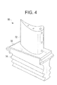
- FIG 4 illustrates a bucket turbine engine component generally designated by reference numeral 50.
- the bucket 50 includes an airfoil portion 52 and a dovetail portion 54.
- the airfoil portion 52 is seated on a platform 56. All of the surfaces are coated with a thermal barrier coating system, an example of which has been shown with reference to Figure 1.
- the platform 56 can undergo spallation as previously described.
- the above noted repair process can be used to repair the platform.
- the repair process since it is locally applied, does not expose the airfoil to the thermal conditions employed during thermal spraying to effect the repair.
- the thermal barrier coating system about the airfoil can crack as a result of the stresses applied to the airfoil during operation.
Landscapes
- Chemical & Material Sciences (AREA)
- Engineering & Computer Science (AREA)
- Mechanical Engineering (AREA)
- Inorganic Chemistry (AREA)
- Materials Engineering (AREA)
- Metallurgy (AREA)
- Chemical Kinetics & Catalysis (AREA)
- Organic Chemistry (AREA)
- General Engineering & Computer Science (AREA)
- Ceramic Engineering (AREA)
- Physics & Mathematics (AREA)
- Plasma & Fusion (AREA)
- Coating By Spraying Or Casting (AREA)
- Turbine Rotor Nozzle Sealing (AREA)
Applications Claiming Priority (1)
| Application Number | Priority Date | Filing Date | Title |
|---|---|---|---|
| US11/361,740 US20070202269A1 (en) | 2006-02-24 | 2006-02-24 | Local repair process of thermal barrier coatings in turbine engine components |
Publications (1)
| Publication Number | Publication Date |
|---|---|
| EP1832668A1 true EP1832668A1 (fr) | 2007-09-12 |
Family
ID=38231190
Family Applications (1)
| Application Number | Title | Priority Date | Filing Date |
|---|---|---|---|
| EP07102932A Withdrawn EP1832668A1 (fr) | 2006-02-24 | 2007-02-23 | Processus de réparation local de revêtements de barrière thermique dans les composants de moteur à turbine |
Country Status (4)
| Country | Link |
|---|---|
| US (1) | US20070202269A1 (fr) |
| EP (1) | EP1832668A1 (fr) |
| JP (1) | JP2007224920A (fr) |
| CN (1) | CN101024880A (fr) |
Cited By (5)
| Publication number | Priority date | Publication date | Assignee | Title |
|---|---|---|---|---|
| EP2177643A1 (fr) * | 2008-10-07 | 2010-04-21 | Siemens Aktiengesellschaft | Procédé de réparation d'un superalliage à l'aide de la même poudre de superalliage et de céramique |
| WO2015082818A1 (fr) | 2013-12-02 | 2015-06-11 | Office National D'etudes Et De Recherches Aérospatiales (Onera) | Procédé de réparation locale de barrières thermiques |
| GB2532605A (en) * | 2014-11-20 | 2016-05-25 | Gen Electric | Modified bucket platforms of turbine buckets and methods for modifying bucket platforms of turbine buckets |
| US10022921B2 (en) | 2013-12-19 | 2018-07-17 | General Electric Company | Turbine component patch delivery systems and methods |
| EP3819399A1 (fr) * | 2019-11-06 | 2021-05-12 | General Electric Company | Système et procédé de revêtement par restauration |
Families Citing this family (23)
| Publication number | Priority date | Publication date | Assignee | Title |
|---|---|---|---|---|
| US20090110953A1 (en) * | 2007-10-29 | 2009-04-30 | General Electric Company | Method of treating a thermal barrier coating and related articles |
| US20110086177A1 (en) * | 2009-10-14 | 2011-04-14 | WALBAR INC. Peabody Industrial Center | Thermal spray method for producing vertically segmented thermal barrier coatings |
| CN101746090A (zh) * | 2010-01-13 | 2010-06-23 | 北京航空航天大学 | 一种高温合金表面抗高温氧化及阻止第二次反应区形成的粘结层及其制备方法 |
| US9102014B2 (en) | 2010-06-17 | 2015-08-11 | Siemens Energy, Inc. | Method of servicing an airfoil assembly for use in a gas turbine engine |
| CN102534613A (zh) * | 2011-12-19 | 2012-07-04 | 北京矿冶研究总院 | 一种新型复合结构涂层及其制备方法 |
| US9260788B2 (en) * | 2012-10-30 | 2016-02-16 | General Electric Company | Reinforced articles and methods of making the same |
| FR3014115B1 (fr) | 2013-12-02 | 2017-04-28 | Office National Detudes Et De Rech Aerospatiales Onera | Procede et systeme de depot d'oxyde sur un composant poreux |
| FR3014477B1 (fr) * | 2013-12-06 | 2016-01-08 | Turbomeca | Rotor a aubes |
| US20150165569A1 (en) * | 2013-12-18 | 2015-06-18 | Petya M. Georgieva | Repair of turbine engine components using waterjet ablation process |
| JP2014159641A (ja) * | 2014-04-17 | 2014-09-04 | Mitsubishi Heavy Ind Ltd | 補修方法およびそれにより補修されたガスタービンの耐熱部材 |
| JP5875623B2 (ja) * | 2014-04-17 | 2016-03-02 | 三菱重工業株式会社 | 補修方法およびそれにより補修されたガスタービンの耐熱部材 |
| WO2016099805A2 (fr) * | 2014-11-21 | 2016-06-23 | General Electric Technology Gmbh | Chemise profilée de chambre de combustion à rideau de flamme |
| US10514170B2 (en) * | 2015-09-18 | 2019-12-24 | General Electric Company | Treatment process, rejuvenation process, treatment composition, and treated component |
| US10646894B2 (en) | 2016-06-30 | 2020-05-12 | General Electric Company | Squeegee apparatus and methods of use thereof |
| US10920590B2 (en) | 2016-06-30 | 2021-02-16 | General Electric Company | Turbine assembly maintenance methods |
| US10384978B2 (en) | 2016-08-22 | 2019-08-20 | General Electric Company | Thermal barrier coating repair compositions and methods of use thereof |
| CN106435584A (zh) * | 2016-10-18 | 2017-02-22 | 安徽工业大学 | 一种热喷涂‑pvd复合涂层及其制备方法 |
| US10717166B2 (en) | 2016-12-02 | 2020-07-21 | General Electric Company | Motorized apparatus for use with rotary machines |
| US10494926B2 (en) | 2017-08-28 | 2019-12-03 | General Electric Company | System and method for maintaining machines |
| JP7398198B2 (ja) * | 2019-03-12 | 2023-12-14 | 三菱重工業株式会社 | タービン動翼及びコンタクト面製造方法 |
| DE102019217580A1 (de) * | 2019-11-14 | 2021-05-20 | Siemens Aktiengesellschaft | Reparatur von beschichteten Bauteilen mittels Designanpassung |
| US20220341019A1 (en) * | 2021-04-23 | 2022-10-27 | Raytheon Technologies Corporation | Case flowpath repair system and method |
| CN115291425A (zh) * | 2022-08-11 | 2022-11-04 | 业成科技(成都)有限公司 | 表面损伤修补方法、显示面板及显示装置 |
Citations (3)
| Publication number | Priority date | Publication date | Assignee | Title |
|---|---|---|---|---|
| EP0430856A1 (fr) * | 1989-11-27 | 1991-06-05 | United Technologies Corporation | Enlèvement par jet d'eau de couches déposées par jet de plasma ou frittées |
| US20040256504A1 (en) * | 2003-06-23 | 2004-12-23 | General Electric Company | Process of selectively removing layers of a thermal barrier coating system |
| US20040261914A1 (en) * | 2001-07-12 | 2004-12-30 | Boucard Bruno Gilles Francois | Method of locally repairing parts covered with a thermal barrier |
Family Cites Families (7)
| Publication number | Priority date | Publication date | Assignee | Title |
|---|---|---|---|---|
| US5972424A (en) * | 1998-05-21 | 1999-10-26 | United Technologies Corporation | Repair of gas turbine engine component coated with a thermal barrier coating |
| US6485780B1 (en) * | 1999-08-23 | 2002-11-26 | General Electric Company | Method for applying coatings on substrates |
| US6165628A (en) * | 1999-08-30 | 2000-12-26 | General Electric Company | Protective coatings for metal-based substrates and related processes |
| US6565680B1 (en) * | 1999-12-27 | 2003-05-20 | General Electric Company | Superalloy weld composition and repaired turbine engine component |
| JP3905724B2 (ja) * | 2001-06-13 | 2007-04-18 | 三菱重工業株式会社 | Ni基合金製部品の補修方法 |
| US6875464B2 (en) * | 2003-04-22 | 2005-04-05 | General Electric Company | In-situ method and composition for repairing a thermal barrier coating |
| US7509735B2 (en) * | 2004-04-22 | 2009-03-31 | Siemens Energy, Inc. | In-frame repairing system of gas turbine components |
-
2006
- 2006-02-24 US US11/361,740 patent/US20070202269A1/en not_active Abandoned
-
2007
- 2007-02-23 EP EP07102932A patent/EP1832668A1/fr not_active Withdrawn
- 2007-02-25 CN CNA2007100059931A patent/CN101024880A/zh active Pending
- 2007-02-26 JP JP2007045109A patent/JP2007224920A/ja not_active Withdrawn
Patent Citations (3)
| Publication number | Priority date | Publication date | Assignee | Title |
|---|---|---|---|---|
| EP0430856A1 (fr) * | 1989-11-27 | 1991-06-05 | United Technologies Corporation | Enlèvement par jet d'eau de couches déposées par jet de plasma ou frittées |
| US20040261914A1 (en) * | 2001-07-12 | 2004-12-30 | Boucard Bruno Gilles Francois | Method of locally repairing parts covered with a thermal barrier |
| US20040256504A1 (en) * | 2003-06-23 | 2004-12-23 | General Electric Company | Process of selectively removing layers of a thermal barrier coating system |
Cited By (6)
| Publication number | Priority date | Publication date | Assignee | Title |
|---|---|---|---|---|
| EP2177643A1 (fr) * | 2008-10-07 | 2010-04-21 | Siemens Aktiengesellschaft | Procédé de réparation d'un superalliage à l'aide de la même poudre de superalliage et de céramique |
| WO2015082818A1 (fr) | 2013-12-02 | 2015-06-11 | Office National D'etudes Et De Recherches Aérospatiales (Onera) | Procédé de réparation locale de barrières thermiques |
| US10022921B2 (en) | 2013-12-19 | 2018-07-17 | General Electric Company | Turbine component patch delivery systems and methods |
| GB2532605A (en) * | 2014-11-20 | 2016-05-25 | Gen Electric | Modified bucket platforms of turbine buckets and methods for modifying bucket platforms of turbine buckets |
| EP3819399A1 (fr) * | 2019-11-06 | 2021-05-12 | General Electric Company | Système et procédé de revêtement par restauration |
| US11549382B2 (en) | 2019-11-06 | 2023-01-10 | General Electric Company | Restoration coating system and method |
Also Published As
| Publication number | Publication date |
|---|---|
| CN101024880A (zh) | 2007-08-29 |
| US20070202269A1 (en) | 2007-08-30 |
| JP2007224920A (ja) | 2007-09-06 |
Similar Documents
| Publication | Publication Date | Title |
|---|---|---|
| EP1832668A1 (fr) | Processus de réparation local de revêtements de barrière thermique dans les composants de moteur à turbine | |
| US20080011813A1 (en) | Repair process for coated articles | |
| EP1881154B1 (fr) | Processus de réparation pour articles recouverts | |
| EP0808913B1 (fr) | Procédé pour la réparation d'un revêtement de barrière thermique | |
| US20100237134A1 (en) | Repair process for coated articles | |
| Nelson et al. | TBC experience in land-based gas turbines | |
| JP5226184B2 (ja) | 超合金部品の補修及び再分類 | |
| US20140248425A1 (en) | Air cooled gas turbine components and methods of manufacturing and repairing same | |
| EP1428908B1 (fr) | Revêtement de barrière thermique protegé par une couche émaillée et méthode pour sa fabrication | |
| US6296447B1 (en) | Gas turbine component having location-dependent protective coatings thereon | |
| US6893750B2 (en) | Thermal barrier coating protected by alumina and method for preparing same | |
| EP1304446A1 (fr) | Méthode pour ramplacer un TBC couche céramique endommageé | |
| EP2053141B1 (fr) | Revêtement protecteur à base d'alumine pour revêtements de barrière thermique et procédé de son dépôt | |
| EP2191930A2 (fr) | Procédé de réparation pour composants de turbine revêtus de TBC | |
| JP2011047049A (ja) | タービン燃焼部品上に保護コーティングを堆積する方法 | |
| EP3748031B1 (fr) | Revêtement réfléchissant et son procédé de revêtement | |
| EP1889948A2 (fr) | Revêtement céramique bicouche | |
| JP2004190140A (ja) | 局部的なMCrAlYコーティングを付着させる方法 | |
| EP1790825B1 (fr) | Procédé d' application d'un revêtement de liaison et un d' couche de barrière thermique sur une surface aluminée | |
| JP4476610B2 (ja) | 金属コーティング及びその上の保護コーティングを有する基材を含む物品及びその調製及び構成部品の復元における使用 | |
| US20100189555A1 (en) | Method and assembly for gas turbine engine airfoils with protective coating | |
| Liburdi et al. | Enabling Technologies for Advanced Turbine Component Life Extension | |
| Nagaraj et al. | Evaluation of High Pressure Turbine Blade Coatings on an LM2500 Rainbow Rotor |
Legal Events
| Date | Code | Title | Description |
|---|---|---|---|
| PUAI | Public reference made under article 153(3) epc to a published international application that has entered the european phase |
Free format text: ORIGINAL CODE: 0009012 |
|
| AK | Designated contracting states |
Kind code of ref document: A1 Designated state(s): AT BE BG CH CY CZ DE DK EE ES FI FR GB GR HU IE IS IT LI LT LU LV MC NL PL PT RO SE SI SK TR |
|
| AX | Request for extension of the european patent |
Extension state: AL BA HR MK YU |
|
| 17P | Request for examination filed |
Effective date: 20080312 |
|
| 17Q | First examination report despatched |
Effective date: 20080411 |
|
| AKX | Designation fees paid |
Designated state(s): CH DE GB IT LI |
|
| STAA | Information on the status of an ep patent application or granted ep patent |
Free format text: STATUS: THE APPLICATION IS DEEMED TO BE WITHDRAWN |
|
| 18D | Application deemed to be withdrawn |
Effective date: 20091020 |