EP1832429A2 - Dispositif pour décorer des pièces à fabriquer - Google Patents
Dispositif pour décorer des pièces à fabriquer Download PDFInfo
- Publication number
- EP1832429A2 EP1832429A2 EP06023120A EP06023120A EP1832429A2 EP 1832429 A2 EP1832429 A2 EP 1832429A2 EP 06023120 A EP06023120 A EP 06023120A EP 06023120 A EP06023120 A EP 06023120A EP 1832429 A2 EP1832429 A2 EP 1832429A2
- Authority
- EP
- European Patent Office
- Prior art keywords
- printing
- workpiece
- image
- printing device
- ink
- Prior art date
- Legal status (The legal status is an assumption and is not a legal conclusion. Google has not performed a legal analysis and makes no representation as to the accuracy of the status listed.)
- Ceased
Links
Images


Classifications
-
- B—PERFORMING OPERATIONS; TRANSPORTING
- B41—PRINTING; LINING MACHINES; TYPEWRITERS; STAMPS
- B41J—TYPEWRITERS; SELECTIVE PRINTING MECHANISMS, i.e. MECHANISMS PRINTING OTHERWISE THAN FROM A FORME; CORRECTION OF TYPOGRAPHICAL ERRORS
- B41J3/00—Typewriters or selective printing or marking mechanisms characterised by the purpose for which they are constructed
- B41J3/28—Typewriters or selective printing or marking mechanisms characterised by the purpose for which they are constructed for printing downwardly on flat surfaces, e.g. of books, drawings, boxes, envelopes, e.g. flat-bed ink-jet printers
-
- B—PERFORMING OPERATIONS; TRANSPORTING
- B41—PRINTING; LINING MACHINES; TYPEWRITERS; STAMPS
- B41J—TYPEWRITERS; SELECTIVE PRINTING MECHANISMS, i.e. MECHANISMS PRINTING OTHERWISE THAN FROM A FORME; CORRECTION OF TYPOGRAPHICAL ERRORS
- B41J11/00—Devices or arrangements of selective printing mechanisms, e.g. ink-jet printers or thermal printers, for supporting or handling copy material in sheet or web form
- B41J11/0015—Devices or arrangements of selective printing mechanisms, e.g. ink-jet printers or thermal printers, for supporting or handling copy material in sheet or web form for treating before, during or after printing or for uniform coating or laminating the copy material before or after printing
- B41J11/002—Curing or drying the ink on the copy materials, e.g. by heating or irradiating
- B41J11/0021—Curing or drying the ink on the copy materials, e.g. by heating or irradiating using irradiation
- B41J11/00214—Curing or drying the ink on the copy materials, e.g. by heating or irradiating using irradiation using UV radiation
-
- B—PERFORMING OPERATIONS; TRANSPORTING
- B41—PRINTING; LINING MACHINES; TYPEWRITERS; STAMPS
- B41J—TYPEWRITERS; SELECTIVE PRINTING MECHANISMS, i.e. MECHANISMS PRINTING OTHERWISE THAN FROM A FORME; CORRECTION OF TYPOGRAPHICAL ERRORS
- B41J2/00—Typewriters or selective printing mechanisms characterised by the printing or marking process for which they are designed
- B41J2/005—Typewriters or selective printing mechanisms characterised by the printing or marking process for which they are designed characterised by bringing liquid or particles selectively into contact with a printing material
- B41J2/01—Ink jet
- B41J2/21—Ink jet for multi-colour printing
- B41J2/2132—Print quality control characterised by dot disposition, e.g. for reducing white stripes or banding
- B41J2/2139—Compensation for malfunctioning nozzles creating dot place or dot size errors
-
- B—PERFORMING OPERATIONS; TRANSPORTING
- B41—PRINTING; LINING MACHINES; TYPEWRITERS; STAMPS
- B41J—TYPEWRITERS; SELECTIVE PRINTING MECHANISMS, i.e. MECHANISMS PRINTING OTHERWISE THAN FROM A FORME; CORRECTION OF TYPOGRAPHICAL ERRORS
- B41J3/00—Typewriters or selective printing or marking mechanisms characterised by the purpose for which they are constructed
- B41J3/407—Typewriters or selective printing or marking mechanisms characterised by the purpose for which they are constructed for marking on special material
-
- B—PERFORMING OPERATIONS; TRANSPORTING
- B41—PRINTING; LINING MACHINES; TYPEWRITERS; STAMPS
- B41J—TYPEWRITERS; SELECTIVE PRINTING MECHANISMS, i.e. MECHANISMS PRINTING OTHERWISE THAN FROM A FORME; CORRECTION OF TYPOGRAPHICAL ERRORS
- B41J3/00—Typewriters or selective printing or marking mechanisms characterised by the purpose for which they are constructed
- B41J3/44—Typewriters or selective printing mechanisms having dual functions or combined with, or coupled to, apparatus performing other functions
-
- H—ELECTRICITY
- H04—ELECTRIC COMMUNICATION TECHNIQUE
- H04N—PICTORIAL COMMUNICATION, e.g. TELEVISION
- H04N1/00—Scanning, transmission or reproduction of documents or the like, e.g. facsimile transmission; Details thereof
- H04N1/46—Colour picture communication systems
- H04N1/56—Processing of colour picture signals
- H04N1/60—Colour correction or control
Definitions
- the invention relates to a device for patterning workpieces, which are preferably at least partially made of wood, wood-based materials or the like, according to the preamble of claim 1.
- a device of the type mentioned is, for example, from the DE 100 31 030 B4 known and has sensors for coarse detection of the contour and thickness of the workpieces to be printed, which are mounted on a conveyor or on a portal.
- sensors for coarse detection of the contour and thickness of the workpieces to be printed which are mounted on a conveyor or on a portal.
- the printed with such devices workpieces often result in a distorted, smeared or blemishes and color deviations exhibiting printed image.
- the invention is based on the idea to provide the printing process by a targeted pre- and / or post-processing on a completely new information base.
- the device according to the invention further comprises at least one image detection sensor.
- the provision of at least one image acquisition sensor opens up completely new possibilities for controlling and optimizing the printing process.
- preprocessing the image detection sensor even before the printing process
- distortions and smears of the printed image which are caused by insufficient relative positioning, can be avoided or minimized.
- an overspray i. That printing beyond a free edge of the workpiece and depositing ink mist on an adjacent surface of the workpiece can be effectively prevented.
- the image detection sensor provided according to the invention can be used effectively for the analysis of the workpiece surface.
- an analysis of the workpiece surface with regard to possible defects, color deviations or the like can be carried out in order to check on this basis, the printing device and, for example, to maintain, clean, adjust, etc.
- Image sensor means at least any device that operates on an optical basis and provides information about the (visible or invisible to humans) appearance, so that a wide variety of facilities can be used, such as spectrophotometers with or without ( RGB) filters.
- the device further comprises a control device, which in combination with the at least one image sensing sensor and the ink-jet printing device stands.
- the image detection sensor can be designed in the context of the present invention in various ways. In view of a fast and precise detection of the respective workpiece surface, however, according to a development of the invention, it is provided that at least one image detection sensor has a camera and / or a color measuring device. In this case, a CCD camera has proven to be particularly advantageous, since the digital data obtained can be passed very easily and quickly to a control device or the like.
- control device may be configured in the context of the present invention in various ways. It is also not excluded that the control device partially requires the intervention of an operator. In view of the desired, improved print image quality, however, according to a development of the invention, it is provided that the control device is set up to receive image data obtained from the image acquisition sensor analyze, and preferably at least in terms of color spectrum and / or defects and / or geometry and / or color space (eg RGB color space) of the respective workpiece.
- image data obtained from the image acquisition sensor analyze, and preferably at least in terms of color spectrum and / or defects and / or geometry and / or color space (eg RGB color space) of the respective workpiece.
- the device further comprises a drying device, in particular a UV drying device.
- a drying device in particular a UV drying device.
- the above-described advantages of the device according to the invention can be achieved particularly advantageously by a method for patterning workpieces according to claim 7.
- the actual image data obtained by the image acquisition are compared with target image data, in particular with regard to color spectrum and / or defects and / or geometry and / or color space (eg RGB color space).
- This target / actual comparison can advantageously be used as a basis for improving the print quality, for example by the measures already described above.
- control device provides, on the basis of the image acquisition by the image acquisition sensor, that the print image actually produced moves as close as possible to the desired print image, ie that an optimum print image quality is achieved.
- control device can take a variety of measures.
- the control device according to an embodiment of the invention corrects the control signal output to the printing device such that the intensity and / or the course of the control pulses are changed to at least one nozzle of the printing device.
- control pulses can be completely eliminated, i. the control signals output to the printing device from the control device can be corrected so that one or more nozzles are switched on or off.
- control device can also determine or decide that the determined target / actual deviation is caused by contamination of the print head, in particular of the nozzles.
- the control device can also determine or decide that the determined target / actual deviation is caused by contamination of the print head, in particular of the nozzles.
- provision is made for cleaning of the printing device on the basis of the desired / actual comparison in the presence of a predetermined desired / actual deviation.
- the controller may decide that basic maintenance of the device or even emergency stop of the device is required.
- the image sensing sensor may operate continuously or discontinuously, and that it may operate during normal operation of the device or even during a verify operation of the device in which, for example, predetermined test patterns are printed and detected by the image sensing sensor.
- the image detection sensor can be placed anywhere on the device, wherein it has proved to be advantageous that at least one image detection sensor is provided on the printing device.
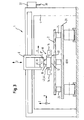
- a device 1 for patterning workpieces 2 as a preferred embodiment of the present invention is shown schematically in FIG. 1 in a perspective view.
- the device is used for patterning and optionally machining workpieces 2, which in the present embodiment at least partially made of wood, wood materials, plastics or the like, as they are often used in the field of furniture and kitchen.
- the device 1 comprises an ink-jet printing device 10, which operates in the present embodiment according to the drop-on-demand principle.
- the ink-jet printing apparatus 10 includes a plurality of nozzles 12 from which ink droplets may be ejected and which are arranged in a plurality of rows in the present embodiment, each row for ejecting a predetermined one Color is provided, for example, the colors cyan, magenta, yellow and black.
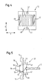
- the printing device 10 is provided in the present embodiment on a spindle unit 6 or in this changed, which is best seen in Fig. 3.
- the spindle unit is preferably such a spindle unit which is also suitable for receiving and exchangeable receiving machining tools or processing units and for this purpose a tool holder 6 'and an interface 6 ", wherein the interface, for example, for the transmission of data , Energy, drive, fluids, etc. may be designed.
- the printing unit 10 is provided in the present embodiment with a connecting piece 18 which is ein anbar in the tool holder 6 'of the spindle unit (see Fig .. 3). Furthermore, the printing unit 10 has transmission means 16 (see Fig. 3) which can communicate with the interface 6 "of the spindle unit, whereby data, energy, drive, fluids, etc. and in particular also ink can be transmitted Printing unit 10 have an ink supply and / or a wireless data transmission device, although this is not shown in the figures.
- the spindle unit 6 is provided in the y-direction movable on a portal 4, which in turn can be designed to be movable in the x-direction.
- a portal 4 which in turn can be designed to be movable in the x-direction.
- two portals 4 are provided in the present embodiment, each of which may carry one or more spindle units 6, which may optionally be arranged on opposite sides of the respective portal 4. It should be noted that the portals 4 may optionally be designed as a boom.
- the spindle units 6 can be automatically or manually equipped with processing tools and / or processing units 30 and one or more printing units 10 via tool magazines 32 respectively provided on the portals 4 (FIG. 3). D. h., The printing units 10 are configured such that they can also be stored in the magazines 32.
- processing tools and / or processing units 30 can be used such as cutting tools (drills, milling cutters, etc.), Kantenanleimaggregate, Extrudieraggregate, coating units, Kaschieraggregate, cleaning units, degreasing units, aggregates to improve the adhesion and wetting properties of surfaces and units to be printed on to reduce the electrostatic charge on the surfaces to be printed.
- cutting tools for cutting tools (drills, milling cutters, etc.), Kantenanleimaggregate, Extrudieraggregate, coating units, Kaschieraggregate, cleaning units, degreasing units, aggregates to improve the adhesion and wetting properties of surfaces and units to be printed on to reduce the electrostatic charge on the surfaces to be printed.
- Kantenanleimaggregate Extrudieraggregate
- coating units coating units
- Kaschieraggregate Kaschieraggregate
- cleaning units degreasing units
- a workpiece table 20 for supporting the respective workpiece to be sampled 2, which is movable in the x-direction shown in Fig. 1.
- the workpiece table 20 can be configured in a variety of ways and for example, be formed by a revolving conveyor belt or the like. Due to its movability, the workpiece table 20 simultaneously forms a workpiece carrying device and a part of the conveying device according to the present invention.
- a plate-shaped workpiece 2 on the workpiece table 20 is shown in more detail in Fig. 2 in a plan view.
- the workpiece table 20 has extendable stop bolts 22, to which the workpiece 2 can be applied for coarse positioning.
- a plurality of distance sensors 52 are arranged on the workpiece table 20, which are part of a coarse detection device 50.
- the distance sensors shown in Fig. 2 are adapted to detect the distance between the sensors and a side surface (narrow surface) of the respective workpiece 2.
- the sensors 52 in the present embodiment are rotatable about an axis extending orthogonally to the surface of the workpiece table 20 and optionally movable parallel to the surface.
- the coarse detection device 50 thus serves for coarse detection of the geometry and positioning of the respective workpiece 2.
- FIG. 3 shows a partially sectioned front view of the device shown in Fig. 1.
- the respective workpiece 2 can be fixed on the workpiece table 20, for example via vacuum cups 24. It is also possible to integrate corresponding suction or suction openings in the workpiece table or a workpiece band.
- the device 1 comprises a detection device 40 for detecting the relative position of the ink-jet printing device 10 and the respective surface of a workpiece 2 to be patterned.
- the detection device 40 has the present invention Embodiment several types of sensors 42, 46, which are best seen in Figures 3, 4 and 5.
- the detection device 40 includes three distance sensors 42 disposed on the pressure device 10 adjacent to the nozzles 12 and measuring in a direction substantially parallel to the ink ejection direction of the nozzles 12 (FIG. 4).
- the absolute distance between the pressure device 10 and the workpiece 2 can be determined with these distance sensors, but beyond that, it is also possible to deduce the exact contour of the respective workpiece 2 from the distance data obtained.
- further distance sensors 42 are each arranged on the printing device 10 via an element 44 pivotable in the present embodiment.
- the pivotable element 44 of the respective sensor can be brought into an extended position, which is best seen in Fig. 5.
- the sensors 42 shown in FIG. 5 measure in a direction that is substantially orthogonal to the ink ejection direction of the nozzles 12. As a result, the thickness or height of the respective area to be printed can be detected and an "overspray" avoided.
- two image sensing sensors 46 are arranged, which also measure in a direction substantially parallel to the ink ejection direction of the nozzles 12. It should be noted, however, that as an alternative or in addition to these image acquisition sensors, one or more image acquisition sensors may be arranged at another suitable location of the device-stationary or movable.
- the image acquisition sensors 46 may be, for example, a CCD camera or the like, which can create a complete image of a printed or already printed area of the respective workpiece 2.
- the control device which evaluates the respective data detected by the sensors and on this basis the operation of the device, in particular the Printing device controls.
- the control device is set up to analyze the image data obtained by the image acquisition sensors at least with regard to color spectrum, defects and geometry of the printed or unprinted workpiece surface.
- drying units 14, for example UV dryers are provided on the printing device 10 (FIG. 3), which serve to rapidly dry the ink applied by the printing device in order to prevent possible distortions or smearing of the printed image.
- the drying units 10 may advantageously also be located between the nozzles 12 and the image sensing sensors 46 so that ink applied to the respective workpiece 2 may be at least partially dried by the drying device 14 prior to image acquisition by an image sensing sensor 46.
- the operation of the device according to the invention can be represented as follows, for example. First, a workpiece 2 is roughly positioned over the stopper pins 22 on the workpiece table 20 and fixed via the vacuum cups 24. Subsequently, the positioning and / or contour of the workpiece 2 are detected on the workpiece table 20 by the sensors 52 and passed this data to the control device.
- the workpiece table 20 is then moved in the x-direction, so that the workpiece 2 can be processed or finished by tools, units or printing units that are inserted into the spindle units 6.
- the operation of the printing device takes place, for example, as follows.
- the printing device 10 On the basis of the data from the sensors 52, the printing device 10 is moved with the corresponding spindle 6 along the portal 4 to the workpiece 2 to be printed.
- the sensors 42, 46 continuously perform a measuring operation, so that the presence and optionally the distance of the respective workpiece and beyond (by the leading image detection sensor 46) also more information about the workpiece 2 can be obtained.
- the controller Based on these data, the controller outputs pressure signals to the respective nozzles 12 (or the associated piezoelectric actuators or thermocouples) so that the workpiece 2 is printed.
- individual nozzles or nozzle groups can be switched on or off in order to compensate for dimensional, position or other tolerances or deviations of the workpiece 2.
- individual or multiple nozzles of the printing device 10 it is equally possible for individual or multiple nozzles of the printing device 10 to be produced via piezo-adjusting means or the like in order to adapt their position or ejection direction to the workpiece 2.
- the sensors 12 are used, which are extendable via pivotable elements 44 in order to detect the height of the narrow surface and thus to prevent overspray.
- drying units 14 After printing on a surface section, it may optionally be dried by the drying units 14, possibly also simultaneously with the printing process.
- the leading image sensing sensor 46 the image sensing sensor 46 at the front in the direction of movement of the printing unit 10
- the trailing image sensing sensor during the printing process image capturing.
- This actual image data is forwarded to the control device and compared with the target image data (i.e., the image data underlying the printing process) with regard to the color spectrum and possible defects of the applied print image. If deviations are detected in this target / actual comparison, the control device can take various measures. In particular, based on the deviation, the control means may correct the control signals (control pulses) outputted to the printing means, for example with regard to the waveform and / or amplitude of the control signals.
- control device can cause the printing process to be interrupted at a suitable time and an automatic or manual cleaning of the printing device to be carried out.
- the printing device can completely stop the operation of the device or output error messages, for example, that maintenance of the printing device is required, other printing inks must be used, etc.
- FIG. 6 shows an operation in the so-called transverse pressure, in which the printing device 10 together with the spindle unit 6 along the portal 4 in the y-direction reciprocated and the workpiece 2 is further clocked by the workpiece table 20 in the x direction.
- the printing scheme shown on the right in FIG. 6, which can be referred to as longitudinal printing.
- the printing device 10 is substantially stationary during the printing process itself, and the workpiece 2 is reciprocated with the workpiece table 20 in the x-direction.
- the printing device 10 thus only needs to be clocked in the y-direction after the printing of a web has been completed.
- combinations of both operations are possible, and it can be printed, for example, obliquely arranged tracks or the like.
Priority Applications (3)
| Application Number | Priority Date | Filing Date | Title |
|---|---|---|---|
| EP06023120A EP1832429A3 (fr) | 2006-03-08 | 2006-11-07 | Dispositif pour décorer des pièces à fabriquer |
| US11/935,924 US7914098B2 (en) | 2006-11-07 | 2007-11-06 | Device for patterning workpieces |
| CN2007101650350A CN101177074B (zh) | 2006-11-07 | 2007-11-06 | 在工件上制作图案的设备及使用该设备制作图案的方法 |
Applications Claiming Priority (6)
| Application Number | Priority Date | Filing Date | Title |
|---|---|---|---|
| EP06004713.1A EP1839883B1 (fr) | 2006-03-08 | 2006-03-08 | Procédé et dispositif pour imprimer sur des objets en forme de plaque |
| EP06012041A EP1867488B1 (fr) | 2006-06-12 | 2006-06-12 | Procédé pour décorer la surface de pièces |
| EP06017769A EP1892108A1 (fr) | 2006-08-25 | 2006-08-25 | Dispositif pour imprimer sur une pièce |
| EP06017767A EP1892107B1 (fr) | 2006-08-25 | 2006-08-25 | Dipositif pour imprimer un motif sur des pièces d'usinage |
| EP06017766.4A EP1837189B1 (fr) | 2006-03-08 | 2006-08-25 | Dispositif pour affiner des pièces à fabriquer |
| EP06023120A EP1832429A3 (fr) | 2006-03-08 | 2006-11-07 | Dispositif pour décorer des pièces à fabriquer |
Publications (2)
| Publication Number | Publication Date |
|---|---|
| EP1832429A2 true EP1832429A2 (fr) | 2007-09-12 |
| EP1832429A3 EP1832429A3 (fr) | 2008-05-28 |
Family
ID=38069064
Family Applications (1)
| Application Number | Title | Priority Date | Filing Date |
|---|---|---|---|
| EP06023120A Ceased EP1832429A3 (fr) | 2006-03-08 | 2006-11-07 | Dispositif pour décorer des pièces à fabriquer |
Country Status (1)
| Country | Link |
|---|---|
| EP (1) | EP1832429A3 (fr) |
Cited By (7)
| Publication number | Priority date | Publication date | Assignee | Title |
|---|---|---|---|---|
| DE202011000732U1 (de) | 2011-03-30 | 2011-06-09 | Stainer, Arno | Holzelemente mit Altholzdekor und Vorrichtung zu deren Herstellung |
| WO2011101144A1 (fr) * | 2010-02-17 | 2011-08-25 | Dieffenbacher System-Automation Gmbh | Dispositif et procédé pour imprimer une image polychrome sur des surfaces de panneaux de matériau, notamment des panneaux de bois |
| WO2011138441A1 (fr) * | 2010-05-07 | 2011-11-10 | SÜDDEKOR GmbH | Procédé et dispositif permettant de réaliser des surfaces tridimensionnelles |
| CN104908438A (zh) * | 2014-03-12 | 2015-09-16 | 广州诺彩数码产品有限公司 | 新型数码印刷机 |
| DE102014116201A1 (de) * | 2014-11-06 | 2016-05-12 | Krones Ag | Vorrichtung und Verfahren zur Kontrolle von Direktdruckmaschinen |
| DE102017205280A1 (de) * | 2017-03-29 | 2018-10-04 | Heidelberger Druckmaschinen Ag | Verfahren zum Einrichten und Betreiben einer Tintendruckmaschine für einen Druckauftrag |
| WO2022248393A1 (fr) * | 2021-05-27 | 2022-12-01 | Homag Gmbh | Dispositif et procédé d'affinement d'une pièce |
Citations (4)
| Publication number | Priority date | Publication date | Assignee | Title |
|---|---|---|---|---|
| US20040263544A1 (en) | 2003-02-19 | 2004-12-30 | Kenji Kojima | Droplet jetting apparatus, an electro-optical apparatus, a method of manufacturing an electro-optical apparatus, and an electronic device |
| DE10031030B4 (de) | 2000-06-26 | 2005-08-04 | Bauer, Jörg R. | Verfahren und Vorrichtung zum Herstellen flächiger Bauteile mit vorbestimmtem Oberflächenaussehen und flächiges Bauteil, insbesondere Frontplatte eines Küchenelements |
| US20060023018A1 (en) | 2004-07-29 | 2006-02-02 | Dainippon Screen Mfg. Co., Ltd. | Print inspection device, printer provided with the same and print inspection method |
| EP1726443A1 (fr) | 2005-04-28 | 2006-11-29 | Homag Holzbearbeitungssysteme AG | Procédé et appareil pour marquer les côtés d'une pièce detacheée plane |
Family Cites Families (2)
| Publication number | Priority date | Publication date | Assignee | Title |
|---|---|---|---|---|
| EP1190864A1 (fr) * | 2000-09-21 | 2002-03-27 | GRETAG IMAGING Trading AG | Procédé et dispositif pour imprimer de l'information d'image numérique |
| GB2384931B (en) * | 2002-01-30 | 2005-06-29 | Hewlett Packard Co | Printer device and method |
-
2006
- 2006-11-07 EP EP06023120A patent/EP1832429A3/fr not_active Ceased
Patent Citations (4)
| Publication number | Priority date | Publication date | Assignee | Title |
|---|---|---|---|---|
| DE10031030B4 (de) | 2000-06-26 | 2005-08-04 | Bauer, Jörg R. | Verfahren und Vorrichtung zum Herstellen flächiger Bauteile mit vorbestimmtem Oberflächenaussehen und flächiges Bauteil, insbesondere Frontplatte eines Küchenelements |
| US20040263544A1 (en) | 2003-02-19 | 2004-12-30 | Kenji Kojima | Droplet jetting apparatus, an electro-optical apparatus, a method of manufacturing an electro-optical apparatus, and an electronic device |
| US20060023018A1 (en) | 2004-07-29 | 2006-02-02 | Dainippon Screen Mfg. Co., Ltd. | Print inspection device, printer provided with the same and print inspection method |
| EP1726443A1 (fr) | 2005-04-28 | 2006-11-29 | Homag Holzbearbeitungssysteme AG | Procédé et appareil pour marquer les côtés d'une pièce detacheée plane |
Cited By (14)
| Publication number | Priority date | Publication date | Assignee | Title |
|---|---|---|---|---|
| WO2011101149A1 (fr) * | 2010-02-17 | 2011-08-25 | Dieffenbacher System-Automation Gmbh | Installation de production et procédé pour imprimer une image polychrome sur des surfaces de panneaux de matériau, notamment des panneaux de bois |
| WO2011101144A1 (fr) * | 2010-02-17 | 2011-08-25 | Dieffenbacher System-Automation Gmbh | Dispositif et procédé pour imprimer une image polychrome sur des surfaces de panneaux de matériau, notamment des panneaux de bois |
| WO2011101150A1 (fr) * | 2010-02-17 | 2011-08-25 | Dieffenbacher System-Automation Gmbh | Dispositif et procédé pour imprimer une image polychrome sur des surfaces de panneaux de matériau, notamment des panneaux de bois |
| RU2564606C2 (ru) * | 2010-05-07 | 2015-10-10 | Зюддекор Гмбх | Способ и устройство для создания трехмерных поверхностей |
| WO2011138441A1 (fr) * | 2010-05-07 | 2011-11-10 | SÜDDEKOR GmbH | Procédé et dispositif permettant de réaliser des surfaces tridimensionnelles |
| DE202011000732U1 (de) | 2011-03-30 | 2011-06-09 | Stainer, Arno | Holzelemente mit Altholzdekor und Vorrichtung zu deren Herstellung |
| CN104908438A (zh) * | 2014-03-12 | 2015-09-16 | 广州诺彩数码产品有限公司 | 新型数码印刷机 |
| CN104908438B (zh) * | 2014-03-12 | 2017-01-04 | 广州诺彩数码产品有限公司 | 新型数码印刷机 |
| DE102014116201A1 (de) * | 2014-11-06 | 2016-05-12 | Krones Ag | Vorrichtung und Verfahren zur Kontrolle von Direktdruckmaschinen |
| US10144237B2 (en) | 2014-11-06 | 2018-12-04 | Krones Ag | Apparatus and method for controlling direct printing machines |
| US11014376B2 (en) | 2014-11-06 | 2021-05-25 | Krones Ag | Apparatus and method for controlling direct printing machines |
| DE102017205280A1 (de) * | 2017-03-29 | 2018-10-04 | Heidelberger Druckmaschinen Ag | Verfahren zum Einrichten und Betreiben einer Tintendruckmaschine für einen Druckauftrag |
| US10226955B2 (en) | 2017-03-29 | 2019-03-12 | Heidelberger Druckmaschinen Ag | Method for setting up and operating an inkjet printing machine for a print job |
| WO2022248393A1 (fr) * | 2021-05-27 | 2022-12-01 | Homag Gmbh | Dispositif et procédé d'affinement d'une pièce |
Also Published As
| Publication number | Publication date |
|---|---|
| EP1832429A3 (fr) | 2008-05-28 |
Similar Documents
| Publication | Publication Date | Title |
|---|---|---|
| EP1892107B1 (fr) | Dipositif pour imprimer un motif sur des pièces d'usinage | |
| EP2065206B1 (fr) | Dispositif d'enrichissement de pièces usinées | |
| US7914098B2 (en) | Device for patterning workpieces | |
| EP1726443B1 (fr) | Procédé et appareil pour marquer les côtés d'une pièce detacheée plane | |
| DE102009000518B4 (de) | Bogendruckmaschine | |
| EP2832546B1 (fr) | Imprimante dotée d'une commande de tête d'impression | |
| EP1832429A2 (fr) | Dispositif pour décorer des pièces à fabriquer | |
| EP2536567A1 (fr) | Dispositif et procédé pour imprimer une image polychrome sur des surfaces de panneaux de matériau, notamment des panneaux de bois | |
| US20090120249A1 (en) | Device For Refining Workpieces | |
| EP1190864A1 (fr) | Procédé et dispositif pour imprimer de l'information d'image numérique | |
| EP1990204A1 (fr) | Procédé et dispositif de revêtement d'une surface | |
| EP2855161B1 (fr) | Imprimante additionnelle dans une presse offset | |
| EP1555132B1 (fr) | Machine pour imprimer les côtes minces des pièces en forme de plaque | |
| DE202009018533U1 (de) | Vorrichtung zum Bedrucken einer nicht-ebenen Oberfläche, sowie Blendenanordnung und Haushaltsgerät | |
| DE102014225206A1 (de) | Druckaggregat | |
| EP2626209B1 (fr) | Procédé et dispositif de reconnaissance de fonctions erronées de douilles d'une imprimante à jet d'encre | |
| DE102013217686A1 (de) | Vorrichtung zum Bedrucken von dreidimensionalen Objekten | |
| DE102014206994A1 (de) | Druckwerk mit zumindest einem Druckkopf und zumindest einer Reinigungsvorrichtung und ein Verfahren zur Reinigung zumindest einer Düsenfläche zumindest eines Druckkopfs | |
| EP4297977A1 (fr) | Machine et procédé de traitement d'une pièce à usiner | |
| AT526342B1 (de) | Vorrichtung und Verfahren zum Bedrucken von Objekten | |
| DE102022115809B3 (de) | Verfahren zum Betreiben einer Tintenstrahldruckmaschine mit einer Auswahlgeschwindigkeit und/oder einer Auswahltaktfrequenz | |
| DE102019111034B4 (de) | Digitaldruckanlage mit bogenförmiger werkstückbahn und verfahren zum bedrucken | |
| DE102014225204A1 (de) | Druckaggregat | |
| DE202006020138U1 (de) | Vorrichtung zum Bemustern von Werkstücken | |
| EP4197799A1 (fr) | Dispositif d'impression et procédé d'impression d'une pièce à usiner |
Legal Events
| Date | Code | Title | Description |
|---|---|---|---|
| PUAI | Public reference made under article 153(3) epc to a published international application that has entered the european phase |
Free format text: ORIGINAL CODE: 0009012 |
|
| AK | Designated contracting states |
Kind code of ref document: A2 Designated state(s): AT BE BG CH CY CZ DE DK EE ES FI FR GB GR HU IE IS IT LI LT LU LV MC NL PL PT RO SE SI SK TR |
|
| AX | Request for extension of the european patent |
Extension state: AL BA HR MK YU |
|
| PUAL | Search report despatched |
Free format text: ORIGINAL CODE: 0009013 |
|
| AK | Designated contracting states |
Kind code of ref document: A3 Designated state(s): AT BE BG CH CY CZ DE DK EE ES FI FR GB GR HU IE IS IT LI LT LU LV MC NL PL PT RO SE SI SK TR |
|
| AX | Request for extension of the european patent |
Extension state: AL BA HR MK RS |
|
| RIC1 | Information provided on ipc code assigned before grant |
Ipc: B41J 2/21 20060101ALI20080421BHEP Ipc: B41J 2/165 20060101ALI20080421BHEP Ipc: H04N 1/00 20060101ALI20080421BHEP Ipc: B44C 5/04 20060101ALI20080421BHEP Ipc: B41J 11/00 20060101ALI20080421BHEP Ipc: B41J 3/44 20060101ALI20080421BHEP Ipc: B41J 3/407 20060101ALI20080421BHEP Ipc: B41J 3/28 20060101AFI20070608BHEP |
|
| 17P | Request for examination filed |
Effective date: 20080731 |
|
| AKX | Designation fees paid |
Designated state(s): DE ES FR IT PL |
|
| 17Q | First examination report despatched |
Effective date: 20090409 |
|
| APAF | Appeal reference modified |
Free format text: ORIGINAL CODE: EPIDOSCREFNE |
|
| APAX | Date of receipt of notice of appeal deleted |
Free format text: ORIGINAL CODE: EPIDOSDNOA2E |
|
| APBK | Appeal reference recorded |
Free format text: ORIGINAL CODE: EPIDOSNREFNE |
|
| APBN | Date of receipt of notice of appeal recorded |
Free format text: ORIGINAL CODE: EPIDOSNNOA2E |
|
| APBR | Date of receipt of statement of grounds of appeal recorded |
Free format text: ORIGINAL CODE: EPIDOSNNOA3E |
|
| APAF | Appeal reference modified |
Free format text: ORIGINAL CODE: EPIDOSCREFNE |
|
| APBT | Appeal procedure closed |
Free format text: ORIGINAL CODE: EPIDOSNNOA9E |
|
| STAA | Information on the status of an ep patent application or granted ep patent |
Free format text: STATUS: THE APPLICATION HAS BEEN REFUSED |
|
| 18R | Application refused |
Effective date: 20160222 |