EP1832429A2 - Device for patterning workpieces - Google Patents
Device for patterning workpieces Download PDFInfo
- Publication number
- EP1832429A2 EP1832429A2 EP06023120A EP06023120A EP1832429A2 EP 1832429 A2 EP1832429 A2 EP 1832429A2 EP 06023120 A EP06023120 A EP 06023120A EP 06023120 A EP06023120 A EP 06023120A EP 1832429 A2 EP1832429 A2 EP 1832429A2
- Authority
- EP
- European Patent Office
- Prior art keywords
- printing
- workpiece
- image
- printing device
- ink
- Prior art date
- Legal status (The legal status is an assumption and is not a legal conclusion. Google has not performed a legal analysis and makes no representation as to the accuracy of the status listed.)
- Ceased
Links
Images


Classifications
-
- B—PERFORMING OPERATIONS; TRANSPORTING
- B41—PRINTING; LINING MACHINES; TYPEWRITERS; STAMPS
- B41J—TYPEWRITERS; SELECTIVE PRINTING MECHANISMS, i.e. MECHANISMS PRINTING OTHERWISE THAN FROM A FORME; CORRECTION OF TYPOGRAPHICAL ERRORS
- B41J3/00—Typewriters or selective printing or marking mechanisms characterised by the purpose for which they are constructed
- B41J3/28—Typewriters or selective printing or marking mechanisms characterised by the purpose for which they are constructed for printing downwardly on flat surfaces, e.g. of books, drawings, boxes, envelopes, e.g. flat-bed ink-jet printers
-
- B—PERFORMING OPERATIONS; TRANSPORTING
- B41—PRINTING; LINING MACHINES; TYPEWRITERS; STAMPS
- B41J—TYPEWRITERS; SELECTIVE PRINTING MECHANISMS, i.e. MECHANISMS PRINTING OTHERWISE THAN FROM A FORME; CORRECTION OF TYPOGRAPHICAL ERRORS
- B41J11/00—Devices or arrangements of selective printing mechanisms, e.g. ink-jet printers or thermal printers, for supporting or handling copy material in sheet or web form
- B41J11/0015—Devices or arrangements of selective printing mechanisms, e.g. ink-jet printers or thermal printers, for supporting or handling copy material in sheet or web form for treating before, during or after printing or for uniform coating or laminating the copy material before or after printing
- B41J11/002—Curing or drying the ink on the copy materials, e.g. by heating or irradiating
- B41J11/0021—Curing or drying the ink on the copy materials, e.g. by heating or irradiating using irradiation
- B41J11/00214—Curing or drying the ink on the copy materials, e.g. by heating or irradiating using irradiation using UV radiation
-
- B—PERFORMING OPERATIONS; TRANSPORTING
- B41—PRINTING; LINING MACHINES; TYPEWRITERS; STAMPS
- B41J—TYPEWRITERS; SELECTIVE PRINTING MECHANISMS, i.e. MECHANISMS PRINTING OTHERWISE THAN FROM A FORME; CORRECTION OF TYPOGRAPHICAL ERRORS
- B41J2/00—Typewriters or selective printing mechanisms characterised by the printing or marking process for which they are designed
- B41J2/005—Typewriters or selective printing mechanisms characterised by the printing or marking process for which they are designed characterised by bringing liquid or particles selectively into contact with a printing material
- B41J2/01—Ink jet
- B41J2/21—Ink jet for multi-colour printing
- B41J2/2132—Print quality control characterised by dot disposition, e.g. for reducing white stripes or banding
- B41J2/2139—Compensation for malfunctioning nozzles creating dot place or dot size errors
-
- B—PERFORMING OPERATIONS; TRANSPORTING
- B41—PRINTING; LINING MACHINES; TYPEWRITERS; STAMPS
- B41J—TYPEWRITERS; SELECTIVE PRINTING MECHANISMS, i.e. MECHANISMS PRINTING OTHERWISE THAN FROM A FORME; CORRECTION OF TYPOGRAPHICAL ERRORS
- B41J3/00—Typewriters or selective printing or marking mechanisms characterised by the purpose for which they are constructed
- B41J3/407—Typewriters or selective printing or marking mechanisms characterised by the purpose for which they are constructed for marking on special material
-
- B—PERFORMING OPERATIONS; TRANSPORTING
- B41—PRINTING; LINING MACHINES; TYPEWRITERS; STAMPS
- B41J—TYPEWRITERS; SELECTIVE PRINTING MECHANISMS, i.e. MECHANISMS PRINTING OTHERWISE THAN FROM A FORME; CORRECTION OF TYPOGRAPHICAL ERRORS
- B41J3/00—Typewriters or selective printing or marking mechanisms characterised by the purpose for which they are constructed
- B41J3/44—Typewriters or selective printing mechanisms having dual functions or combined with, or coupled to, apparatus performing other functions
-
- H—ELECTRICITY
- H04—ELECTRIC COMMUNICATION TECHNIQUE
- H04N—PICTORIAL COMMUNICATION, e.g. TELEVISION
- H04N1/00—Scanning, transmission or reproduction of documents or the like, e.g. facsimile transmission; Details thereof
- H04N1/46—Colour picture communication systems
- H04N1/56—Processing of colour picture signals
- H04N1/60—Colour correction or control
Definitions
- the invention relates to a device for patterning workpieces, which are preferably at least partially made of wood, wood-based materials or the like, according to the preamble of claim 1.
- a device of the type mentioned is, for example, from the DE 100 31 030 B4 known and has sensors for coarse detection of the contour and thickness of the workpieces to be printed, which are mounted on a conveyor or on a portal.
- sensors for coarse detection of the contour and thickness of the workpieces to be printed which are mounted on a conveyor or on a portal.
- the printed with such devices workpieces often result in a distorted, smeared or blemishes and color deviations exhibiting printed image.
- the invention is based on the idea to provide the printing process by a targeted pre- and / or post-processing on a completely new information base.
- the device according to the invention further comprises at least one image detection sensor.
- the provision of at least one image acquisition sensor opens up completely new possibilities for controlling and optimizing the printing process.
- preprocessing the image detection sensor even before the printing process
- distortions and smears of the printed image which are caused by insufficient relative positioning, can be avoided or minimized.
- an overspray i. That printing beyond a free edge of the workpiece and depositing ink mist on an adjacent surface of the workpiece can be effectively prevented.
- the image detection sensor provided according to the invention can be used effectively for the analysis of the workpiece surface.
- an analysis of the workpiece surface with regard to possible defects, color deviations or the like can be carried out in order to check on this basis, the printing device and, for example, to maintain, clean, adjust, etc.
- Image sensor means at least any device that operates on an optical basis and provides information about the (visible or invisible to humans) appearance, so that a wide variety of facilities can be used, such as spectrophotometers with or without ( RGB) filters.
- the device further comprises a control device, which in combination with the at least one image sensing sensor and the ink-jet printing device stands.
- the image detection sensor can be designed in the context of the present invention in various ways. In view of a fast and precise detection of the respective workpiece surface, however, according to a development of the invention, it is provided that at least one image detection sensor has a camera and / or a color measuring device. In this case, a CCD camera has proven to be particularly advantageous, since the digital data obtained can be passed very easily and quickly to a control device or the like.
- control device may be configured in the context of the present invention in various ways. It is also not excluded that the control device partially requires the intervention of an operator. In view of the desired, improved print image quality, however, according to a development of the invention, it is provided that the control device is set up to receive image data obtained from the image acquisition sensor analyze, and preferably at least in terms of color spectrum and / or defects and / or geometry and / or color space (eg RGB color space) of the respective workpiece.
- image data obtained from the image acquisition sensor analyze, and preferably at least in terms of color spectrum and / or defects and / or geometry and / or color space (eg RGB color space) of the respective workpiece.
- the device further comprises a drying device, in particular a UV drying device.
- a drying device in particular a UV drying device.
- the above-described advantages of the device according to the invention can be achieved particularly advantageously by a method for patterning workpieces according to claim 7.
- the actual image data obtained by the image acquisition are compared with target image data, in particular with regard to color spectrum and / or defects and / or geometry and / or color space (eg RGB color space).
- This target / actual comparison can advantageously be used as a basis for improving the print quality, for example by the measures already described above.
- control device provides, on the basis of the image acquisition by the image acquisition sensor, that the print image actually produced moves as close as possible to the desired print image, ie that an optimum print image quality is achieved.
- control device can take a variety of measures.
- the control device according to an embodiment of the invention corrects the control signal output to the printing device such that the intensity and / or the course of the control pulses are changed to at least one nozzle of the printing device.
- control pulses can be completely eliminated, i. the control signals output to the printing device from the control device can be corrected so that one or more nozzles are switched on or off.
- control device can also determine or decide that the determined target / actual deviation is caused by contamination of the print head, in particular of the nozzles.
- the control device can also determine or decide that the determined target / actual deviation is caused by contamination of the print head, in particular of the nozzles.
- provision is made for cleaning of the printing device on the basis of the desired / actual comparison in the presence of a predetermined desired / actual deviation.
- the controller may decide that basic maintenance of the device or even emergency stop of the device is required.
- the image sensing sensor may operate continuously or discontinuously, and that it may operate during normal operation of the device or even during a verify operation of the device in which, for example, predetermined test patterns are printed and detected by the image sensing sensor.
- the image detection sensor can be placed anywhere on the device, wherein it has proved to be advantageous that at least one image detection sensor is provided on the printing device.
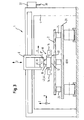
- a device 1 for patterning workpieces 2 as a preferred embodiment of the present invention is shown schematically in FIG. 1 in a perspective view.
- the device is used for patterning and optionally machining workpieces 2, which in the present embodiment at least partially made of wood, wood materials, plastics or the like, as they are often used in the field of furniture and kitchen.
- the device 1 comprises an ink-jet printing device 10, which operates in the present embodiment according to the drop-on-demand principle.
- the ink-jet printing apparatus 10 includes a plurality of nozzles 12 from which ink droplets may be ejected and which are arranged in a plurality of rows in the present embodiment, each row for ejecting a predetermined one Color is provided, for example, the colors cyan, magenta, yellow and black.
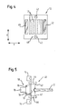
- the printing device 10 is provided in the present embodiment on a spindle unit 6 or in this changed, which is best seen in Fig. 3.
- the spindle unit is preferably such a spindle unit which is also suitable for receiving and exchangeable receiving machining tools or processing units and for this purpose a tool holder 6 'and an interface 6 ", wherein the interface, for example, for the transmission of data , Energy, drive, fluids, etc. may be designed.
- the printing unit 10 is provided in the present embodiment with a connecting piece 18 which is ein anbar in the tool holder 6 'of the spindle unit (see Fig .. 3). Furthermore, the printing unit 10 has transmission means 16 (see Fig. 3) which can communicate with the interface 6 "of the spindle unit, whereby data, energy, drive, fluids, etc. and in particular also ink can be transmitted Printing unit 10 have an ink supply and / or a wireless data transmission device, although this is not shown in the figures.
- the spindle unit 6 is provided in the y-direction movable on a portal 4, which in turn can be designed to be movable in the x-direction.
- a portal 4 which in turn can be designed to be movable in the x-direction.
- two portals 4 are provided in the present embodiment, each of which may carry one or more spindle units 6, which may optionally be arranged on opposite sides of the respective portal 4. It should be noted that the portals 4 may optionally be designed as a boom.
- the spindle units 6 can be automatically or manually equipped with processing tools and / or processing units 30 and one or more printing units 10 via tool magazines 32 respectively provided on the portals 4 (FIG. 3). D. h., The printing units 10 are configured such that they can also be stored in the magazines 32.
- processing tools and / or processing units 30 can be used such as cutting tools (drills, milling cutters, etc.), Kantenanleimaggregate, Extrudieraggregate, coating units, Kaschieraggregate, cleaning units, degreasing units, aggregates to improve the adhesion and wetting properties of surfaces and units to be printed on to reduce the electrostatic charge on the surfaces to be printed.
- cutting tools for cutting tools (drills, milling cutters, etc.), Kantenanleimaggregate, Extrudieraggregate, coating units, Kaschieraggregate, cleaning units, degreasing units, aggregates to improve the adhesion and wetting properties of surfaces and units to be printed on to reduce the electrostatic charge on the surfaces to be printed.
- Kantenanleimaggregate Extrudieraggregate
- coating units coating units
- Kaschieraggregate Kaschieraggregate
- cleaning units degreasing units
- a workpiece table 20 for supporting the respective workpiece to be sampled 2, which is movable in the x-direction shown in Fig. 1.
- the workpiece table 20 can be configured in a variety of ways and for example, be formed by a revolving conveyor belt or the like. Due to its movability, the workpiece table 20 simultaneously forms a workpiece carrying device and a part of the conveying device according to the present invention.
- a plate-shaped workpiece 2 on the workpiece table 20 is shown in more detail in Fig. 2 in a plan view.
- the workpiece table 20 has extendable stop bolts 22, to which the workpiece 2 can be applied for coarse positioning.
- a plurality of distance sensors 52 are arranged on the workpiece table 20, which are part of a coarse detection device 50.
- the distance sensors shown in Fig. 2 are adapted to detect the distance between the sensors and a side surface (narrow surface) of the respective workpiece 2.
- the sensors 52 in the present embodiment are rotatable about an axis extending orthogonally to the surface of the workpiece table 20 and optionally movable parallel to the surface.
- the coarse detection device 50 thus serves for coarse detection of the geometry and positioning of the respective workpiece 2.
- FIG. 3 shows a partially sectioned front view of the device shown in Fig. 1.
- the respective workpiece 2 can be fixed on the workpiece table 20, for example via vacuum cups 24. It is also possible to integrate corresponding suction or suction openings in the workpiece table or a workpiece band.
- the device 1 comprises a detection device 40 for detecting the relative position of the ink-jet printing device 10 and the respective surface of a workpiece 2 to be patterned.
- the detection device 40 has the present invention Embodiment several types of sensors 42, 46, which are best seen in Figures 3, 4 and 5.
- the detection device 40 includes three distance sensors 42 disposed on the pressure device 10 adjacent to the nozzles 12 and measuring in a direction substantially parallel to the ink ejection direction of the nozzles 12 (FIG. 4).
- the absolute distance between the pressure device 10 and the workpiece 2 can be determined with these distance sensors, but beyond that, it is also possible to deduce the exact contour of the respective workpiece 2 from the distance data obtained.
- further distance sensors 42 are each arranged on the printing device 10 via an element 44 pivotable in the present embodiment.
- the pivotable element 44 of the respective sensor can be brought into an extended position, which is best seen in Fig. 5.
- the sensors 42 shown in FIG. 5 measure in a direction that is substantially orthogonal to the ink ejection direction of the nozzles 12. As a result, the thickness or height of the respective area to be printed can be detected and an "overspray" avoided.
- two image sensing sensors 46 are arranged, which also measure in a direction substantially parallel to the ink ejection direction of the nozzles 12. It should be noted, however, that as an alternative or in addition to these image acquisition sensors, one or more image acquisition sensors may be arranged at another suitable location of the device-stationary or movable.
- the image acquisition sensors 46 may be, for example, a CCD camera or the like, which can create a complete image of a printed or already printed area of the respective workpiece 2.
- the control device which evaluates the respective data detected by the sensors and on this basis the operation of the device, in particular the Printing device controls.
- the control device is set up to analyze the image data obtained by the image acquisition sensors at least with regard to color spectrum, defects and geometry of the printed or unprinted workpiece surface.
- drying units 14, for example UV dryers are provided on the printing device 10 (FIG. 3), which serve to rapidly dry the ink applied by the printing device in order to prevent possible distortions or smearing of the printed image.
- the drying units 10 may advantageously also be located between the nozzles 12 and the image sensing sensors 46 so that ink applied to the respective workpiece 2 may be at least partially dried by the drying device 14 prior to image acquisition by an image sensing sensor 46.
- the operation of the device according to the invention can be represented as follows, for example. First, a workpiece 2 is roughly positioned over the stopper pins 22 on the workpiece table 20 and fixed via the vacuum cups 24. Subsequently, the positioning and / or contour of the workpiece 2 are detected on the workpiece table 20 by the sensors 52 and passed this data to the control device.
- the workpiece table 20 is then moved in the x-direction, so that the workpiece 2 can be processed or finished by tools, units or printing units that are inserted into the spindle units 6.
- the operation of the printing device takes place, for example, as follows.
- the printing device 10 On the basis of the data from the sensors 52, the printing device 10 is moved with the corresponding spindle 6 along the portal 4 to the workpiece 2 to be printed.
- the sensors 42, 46 continuously perform a measuring operation, so that the presence and optionally the distance of the respective workpiece and beyond (by the leading image detection sensor 46) also more information about the workpiece 2 can be obtained.
- the controller Based on these data, the controller outputs pressure signals to the respective nozzles 12 (or the associated piezoelectric actuators or thermocouples) so that the workpiece 2 is printed.
- individual nozzles or nozzle groups can be switched on or off in order to compensate for dimensional, position or other tolerances or deviations of the workpiece 2.
- individual or multiple nozzles of the printing device 10 it is equally possible for individual or multiple nozzles of the printing device 10 to be produced via piezo-adjusting means or the like in order to adapt their position or ejection direction to the workpiece 2.
- the sensors 12 are used, which are extendable via pivotable elements 44 in order to detect the height of the narrow surface and thus to prevent overspray.
- drying units 14 After printing on a surface section, it may optionally be dried by the drying units 14, possibly also simultaneously with the printing process.
- the leading image sensing sensor 46 the image sensing sensor 46 at the front in the direction of movement of the printing unit 10
- the trailing image sensing sensor during the printing process image capturing.
- This actual image data is forwarded to the control device and compared with the target image data (i.e., the image data underlying the printing process) with regard to the color spectrum and possible defects of the applied print image. If deviations are detected in this target / actual comparison, the control device can take various measures. In particular, based on the deviation, the control means may correct the control signals (control pulses) outputted to the printing means, for example with regard to the waveform and / or amplitude of the control signals.
- control device can cause the printing process to be interrupted at a suitable time and an automatic or manual cleaning of the printing device to be carried out.
- the printing device can completely stop the operation of the device or output error messages, for example, that maintenance of the printing device is required, other printing inks must be used, etc.
- FIG. 6 shows an operation in the so-called transverse pressure, in which the printing device 10 together with the spindle unit 6 along the portal 4 in the y-direction reciprocated and the workpiece 2 is further clocked by the workpiece table 20 in the x direction.
- the printing scheme shown on the right in FIG. 6, which can be referred to as longitudinal printing.
- the printing device 10 is substantially stationary during the printing process itself, and the workpiece 2 is reciprocated with the workpiece table 20 in the x-direction.
- the printing device 10 thus only needs to be clocked in the y-direction after the printing of a web has been completed.
- combinations of both operations are possible, and it can be printed, for example, obliquely arranged tracks or the like.
Abstract
Description
Die Erfindung betrifft eine Vorrichtung zum Bemustern von Werkstücken, die bevorzugt zumindest teilweise aus Holz, Holzwerkstoffen oder dergleichen bestehen, nach dem Oberbegriff von Anspruch 1.The invention relates to a device for patterning workpieces, which are preferably at least partially made of wood, wood-based materials or the like, according to the preamble of claim 1.
Eine Vorrichtung der eingangs genannten Art ist beispielsweise aus der
Ferner betrifft die von der Anmelderin eingereichte, noch nicht veröffentlichte Europäische Patentanmeldung
Es ist daher Aufgabe der vorliegenden Erfindung, eine gattungsgemäße Vorrichtung zum Bemustern von Werkstücken bereitzustellen, die eine verbesserte Druckbildqualität ermöglicht.It is therefore an object of the present invention, a generic device for patterning of workpieces to provide an improved print image quality.
Diese Aufgabe wird erfindungsgemäß durch eine Vorrichtung nach Anspruch 1 und ein Verfahren nach Anspruch 7 gelöst. Besonders vorteilhafte Weiterbildungen der Erfindung sind in den abhängigen Ansprüchen angegeben.This object is achieved by a device according to claim 1 and a method according to claim 7. Particularly advantageous developments of the invention are specified in the dependent claims.
Der Erfindung liegt der Gedanke zugrunde, den Druckvorgang durch ein gezieltes Pre- und/oder Postprocessing auf eine völlig neue Informationsbasis zu stellen. Zu diesem Zweck ist vorgesehen, dass die erfindungsgemäße Vorrichtung ferner mindestens einen Bilderfassungssensor aufweist. Durch das Vorsehen mindestens eines Bilderfassungssensors werden völlig neue Möglichkeiten zur Steuerung und Optimierung des Druckvorganges eröffnet. So wird es beispielsweise möglich, schon vor dem Druckvorgang ("Preprocessing") die genaue Relativposition des Werkstücks in Bezug auf die Druckeinrichtung durch den Bilderfassungssensor zu bestimmen. Hierdurch können Verzerrungen und Verschmierungen des Druckbildes, die durch eine unzureichende Relativpositionierung verursacht werden, vermieden oder minimiert werden. Auch ein "Overspray", d.h. dass über einen freien Rand des Werkstücks hinaus gedruckt wird und sich Tintennebel auf einer benachbarten Oberfläche des Werkstücks absetzt, kann wirksam verhindert werden.The invention is based on the idea to provide the printing process by a targeted pre- and / or post-processing on a completely new information base. For this purpose, it is provided that the device according to the invention further comprises at least one image detection sensor. The provision of at least one image acquisition sensor opens up completely new possibilities for controlling and optimizing the printing process. Thus, for example, it is possible to determine the exact relative position of the workpiece with respect to the printing device by the image detection sensor even before the printing process ("preprocessing"). As a result, distortions and smears of the printed image, which are caused by insufficient relative positioning, can be avoided or minimized. Also an overspray, i. That printing beyond a free edge of the workpiece and depositing ink mist on an adjacent surface of the workpiece can be effectively prevented.
Aber auch nach einem Druckvorgang (bzw. vor einem nachfolgenden Druckvorgang) kann der erfindungsgemäß vorgesehene Bilderfassungssensor wirksam zur Analyse der Werkstückoberfläche eingesetzt werden. Beispielsweise kann mittels des Bildsensors eine Analyse der Werkstückoberfläche im Hinblick auf mögliche Fehlstellen, Farbabweichungen oder dergleichen durchgeführt werden, um auf dieser Grundlage die Druckeinrichtung zu überprüfen und beispielsweise zu warten, zu reinigen, zu justieren etc.But even after a printing operation (or before a subsequent printing process), the image detection sensor provided according to the invention can be used effectively for the analysis of the workpiece surface. For example, by means of the image sensor, an analysis of the workpiece surface with regard to possible defects, color deviations or the like can be carried out in order to check on this basis, the printing device and, for example, to maintain, clean, adjust, etc.
Durch diese und weitere mögliche Anwendungen des Bilderfassungssensors kann die Druckbildqualität gegenüber dem Stand der Technik deutlich erhöht werden. Dabei ist unter Bilderfassungssensor zumindest jegliche Einrichtung zu verstehen, die auf optischer Basis arbeitet und Informationen über das (für den Menschen sichtbaren oder nicht sichtbare) Erscheinungsbild liefert, so dass eine große Vielfalt von Einrichtungen eingesetzt werden kann, wie beispielsweise auch Spektralphotometer mit oder ohne (RGB-)Filter.Through these and other possible applications of the image acquisition sensor, the print quality can be significantly increased over the prior art. Image sensor means at least any device that operates on an optical basis and provides information about the (visible or invisible to humans) appearance, so that a wide variety of facilities can be used, such as spectrophotometers with or without ( RGB) filters.
Um die oben beschriebenen und weitere mögliche Anwendungen des Bilderfassungssensors effizient zur Verbesserung der Druckbildqualität umsetzen zu können, ist gemäß einer Weiterbildung der Erfindung vorgesehen, dass die Vorrichtung ferner eine Steuereinrichtung aufweist, die mit dem mindestens einen Bilderfassungssensor und der Ink-Jet-Druckeinrichtung in Verbindung steht.In order to be able to efficiently implement the above-described and further possible applications of the image acquisition sensor for improving the print image quality, it is provided according to a development of the invention that the device further comprises a control device, which in combination with the at least one image sensing sensor and the ink-jet printing device stands.
Der Bilderfassungssensor kann im Rahmen der vorliegenden Erfindung auf unterschiedlichste Art und Weise ausgestaltet sein. Im Hinblick auf eine schnelle und präzise Erfassung der jeweiligen Werkstückoberfläche ist gemäß einer Weiterbildung der Erfindung jedoch vorgesehen, dass mindestens ein Bilderfassungssensor eine Kamera und/oder ein Farbmessgerät aufweist. Dabei hat sich eine CCD-Kamera als besonders vorteilhaft erwiesen, da die erhaltenen digitalen Daten besonders einfach und schnell an eine Steuereinrichtung oder dergleichen weitergegeben werden können.The image detection sensor can be designed in the context of the present invention in various ways. In view of a fast and precise detection of the respective workpiece surface, however, according to a development of the invention, it is provided that at least one image detection sensor has a camera and / or a color measuring device. In this case, a CCD camera has proven to be particularly advantageous, since the digital data obtained can be passed very easily and quickly to a control device or the like.
Auch die Steuereinrichtung kann im Rahmen der vorliegenden Erfindung auf unterschiedlichste Art und Weise ausgestaltet sein. Es ist auch nicht ausgeschlossen, dass die Steuereinrichtung teilweise den Eingriff einer Bedienperson erfordert. Im Hinblick auf die angestrebte, verbesserte Druckbildqualität ist gemäß einer Weiterbildung der Erfindung jedoch vorgesehen, dass die Steuereinrichtung eingerichtet ist, von dem Bilderfassungssensor erhaltene Bilddaten zu analysieren, und zwar bevorzugt zumindest hinsichtlich Farbspektrum und/oder Fehlstellen und/oder Geometrie und/oder Farbraum (z. B. RGB-Farbraum) des jeweiligen Werkstücks.The control device may be configured in the context of the present invention in various ways. It is also not excluded that the control device partially requires the intervention of an operator. In view of the desired, improved print image quality, however, according to a development of the invention, it is provided that the control device is set up to receive image data obtained from the image acquisition sensor analyze, and preferably at least in terms of color spectrum and / or defects and / or geometry and / or color space (eg RGB color space) of the respective workpiece.
Gerade beim Einsatz des mindestens einen Bilderfassungssensors zur Erfassung des Farbspektrums, aber auch der Fehlstellen, ist es wichtig, dass zum Erfassungszeitpunkt ein reproduzierbares Druckbild vorliegt. Vor diesem Hintergrund ist gemäß einer Weiterbildung der Erfindung vorgesehen, dass die Vorrichtung ferner eine Trocknungseinrichtung, insbesondere eine UV-Trocknungseinrichtung aufweist. Hierdurch kann ein vorbestimmter Trocknungszustand der aufgebrachten Tinte erzeugt werden, bevor die jeweilige Bilderfassung durchgeführt ist.Especially when using the at least one image acquisition sensor for detecting the color spectrum, but also the defects, it is important that there is a reproducible print image at the time of acquisition. Against this background, it is provided according to a development of the invention that the device further comprises a drying device, in particular a UV drying device. Thereby, a predetermined drying state of the applied ink can be generated before the respective image acquisition is performed.
Die oben beschriebenen Vorteile der erfindungsgemäßen Vorrichtung lassen sich besonders vorteilhaft durch ein Verfahren zum Bemustern von Werkstücken gemäß Anspruch 7 erzielen. Dabei ist es besonders bevorzugt, dass die durch die Bilderfassung erhaltenen Ist-Bilddaten mit Soll-Bilddaten verglichen werden und zwar insbesondere hinsichtlich Farbspektrum und/oder Fehlstellen und/oder Geometrie und/oder Farbraum (z. B. RGB-Farbraum). Dieser Soll-/Ist-Vergleich kann vorteilhaft als Grundlage für eine Verbesserung der Druckqualität, beispielsweise durch die bereits oben beschriebenen Maßnahmen, herangezogen werden.The above-described advantages of the device according to the invention can be achieved particularly advantageously by a method for patterning workpieces according to claim 7. In this case, it is particularly preferred that the actual image data obtained by the image acquisition are compared with target image data, in particular with regard to color spectrum and / or defects and / or geometry and / or color space (eg RGB color space). This target / actual comparison can advantageously be used as a basis for improving the print quality, for example by the measures already described above.
Dabei ist gemäß einer Weiterbildung der Erfindung vorgesehen, dass die von der Steuereinrichtung zur Druckeinrichtung ausgegebenen Steuersignale auf der Grundlage des Soll-/Ist-Vergleichs korrigiert werden, um die Soll-/Ist-Abweichung zu minimieren. Die Steuereinrichtung sorgt somit auf der Grundlage der Bilderfassung durch den Bilderfassungssensor, dass das tatsächlich erstellte Druckbild sich möglichst nahe am gewünschten Druckbild bewegt, d.h. dass eine optimale Druckbildqualität erzielt wird.It is provided according to a development of the invention that the output from the control device to the printing device control signals are corrected on the basis of the target / actual comparison in order to minimize the target / actual deviation. The control device thus provides, on the basis of the image acquisition by the image acquisition sensor, that the print image actually produced moves as close as possible to the desired print image, ie that an optimum print image quality is achieved.
Um dies zu erreichen, kann die Steuereinrichtung unterschiedlichste Maßnahmen treffen. Als besonders wirksam hat es sich jedoch erwiesen, dass die Steuereinrichtung gemäß einer Weiterbildung der Erfindung die zur Druckeinrichtung ausgegebenen Steuersignal derart korrigiert, dass die Intensität und/oder der Verlauf der Steuerimpulse zu mindestens einer Düse der Druckeinrichtung verändert werden. Dabei können Steuerimpulse auch vollständig entfallen, d.h. die von der Steuereinrichtung zur Druckeinrichtung ausgegebenen Steuersignale können derart korrigiert werden, dass eine oder mehrere Düsen zu- oder abgeschaltet werden.To achieve this, the control device can take a variety of measures. However, it has proved to be particularly effective that the control device according to an embodiment of the invention corrects the control signal output to the printing device such that the intensity and / or the course of the control pulses are changed to at least one nozzle of the printing device. In this case, control pulses can be completely eliminated, i. the control signals output to the printing device from the control device can be corrected so that one or more nozzles are switched on or off.
Alternativ oder zusätzlich kann die Steuereinrichtung jedoch auch feststellen bzw. entscheiden, dass die ermittelte Soll-/Ist-Abweichung durch eine Verschmutzung des Druckkopfes, insbesondere der Düsen, verursacht wird. Für diesen Fall ist gemäß einer Weiterbildung des erfindungsgemäßen Verfahrens vorgesehen, dass auf der Grundlage des Soll-/Ist-Vergleichs bei Vorliegen einer vorbestimmten Soll-/Ist-Abweichung eine Reinigung der Druckeinrichtung durchgeführt wird. Auch kann die Steuereinrichtung, beispielsweise bei Fehlschlagen von Korrekturmaßnahmen, entscheiden, dass eine grundlegende Wartung der Vorrichtung oder sogar ein Nothalt der Vorrichtung erforderlich ist.Alternatively or additionally, however, the control device can also determine or decide that the determined target / actual deviation is caused by contamination of the print head, in particular of the nozzles. In this case, according to a development of the method according to the invention, provision is made for cleaning of the printing device on the basis of the desired / actual comparison in the presence of a predetermined desired / actual deviation. Also, for example, if corrective action fails, the controller may decide that basic maintenance of the device or even emergency stop of the device is required.
Ferner ist zu beachten, dass der Bilderfassungssensor kontinuierlich oder diskontinuierlich arbeiten kann, und dass er während des normalen Betriebs der Vorrichtung oder auch während eines Überprüfungsbetriebes der Vorrichtung, in welchem beispielsweise vorbestimmte Testmuster gedruckt und durch den Bilderfassungssensor erfasst werden, arbeiten kann. Ferner kann der Bilderfassungssensor an einer beliebigen Stelle der Vorrichtung platziert sein, wobei es sich als vorteilhaft erwiesen hat, dass zumindest ein Bilderfassungssensor an der Druckeinrichtung vorgesehen ist.It should also be noted that the image sensing sensor may operate continuously or discontinuously, and that it may operate during normal operation of the device or even during a verify operation of the device in which, for example, predetermined test patterns are printed and detected by the image sensing sensor. Furthermore, the image detection sensor can be placed anywhere on the device, wherein it has proved to be advantageous that at least one image detection sensor is provided on the printing device.
- Fig. 1Fig. 1
- zeigt schematisch eine Perspektivansicht einer Vorrichtung zum Bemustern von Werkstücken gemäß einer Ausführungsform der Erfindung;shows schematically a perspective view of a device for patterning workpieces according to an embodiment of the invention;
- Fig. 2Fig. 2
- zeigt schematisch eine teilweise Draufsicht der in Fig. 1 gezeigten Vorrichtung;shows schematically a partial plan view of the device shown in Figure 1;
- Fig. 3Fig. 3
- zeigt schematisch eine teilweise geschnittene Frontansicht der in Fig. 1 gezeigten Vorrichtung;shows schematically a partially cutaway front view of the device shown in Figure 1;
- Fig. 4Fig. 4
- zeigt weitere Details der Druckeinrichtung in Fig. 1 gezeigten Vorrichtung;shows further details of the printing device in Fig. 1 apparatus shown;
- Fig. 5Fig. 5
- zeigt weitere Details der Druckeinrichtung der in Fig. 1 gezeigten Vorrichtung;shows further details of the printing device of the device shown in Fig. 1;
- Fig. 6Fig. 6
- veranschaulicht den Betrieb der in Fig. 1 gezeigten Vorrichtung.illustrates the operation of the device shown in Fig. 1.
Bevorzugte Ausführungsformen der vorliegenden Erfindung werden nachfolgend ausführlich unter Bezugnahme auf die begleitenden Zeichnungen beschrieben.Preferred embodiments of the present invention will be described below in detail with reference to the accompanying drawings.
Eine Vorrichtung 1 zum Bemustern von Werkstücken 2 als bevorzugte Ausführungsform der vorliegenden Erfindung ist in Fig. 1 schematisch in einer Perspektivansicht gezeigt. Die Vorrichtung dient zum Bemustern und ggf. Bearbeiten von Werkstücken 2, die in der vorliegenden Ausführungsform zumindest teilweise aus Holz, Holzwerkstoffen, Kunststoffen oder dergleichen bestehen, wie sie im Bereich des Möbel- und Küchenbaus häufig zum Einsatz kommen.A device 1 for
Die Vorrichtung 1 umfasst eine Ink-Jet-Druckeinrichtung 10, die in der vorliegenden Ausführungsform nach dem Drop-on-Demand-Prinzip arbeitet. Wie in Fig. 4 am besten zu erkennen ist, umfasst die Ink-Jet-Druckeinrichtung 10 eine Mehrzahl von Düsen 12, aus denen Tintentropfen ausgestoßen werden können und die in der vorliegenden Ausführungsform in mehreren Reihen angeordnet sind, wobei jede Reihe zum Ausstoßen einer vorbestimmten Farbe vorgesehen ist, beispielsweise den Farben Cyan, Magenta, Gelb und Schwarz.The device 1 comprises an ink-
Die Druckeinrichtung 10 ist in der vorliegenden Ausführungsform an einer Spindeleinheit 6 vorgesehen bzw. in diese eingewechselt, was in Fig. 3 am besten zu erkennen ist. Bei der Spindeleinheit handelt es sich bevorzugt um eine solche Spindeleinheit, die auch zur ein- und auswechselbaren Aufnahme von Bearbeitungswerkzeugen oder Bearbeitungsaggregaten geeignet ist und die zu diesem Zweck eine Werkzeugaufnahme 6' und eine Schnittstelle 6" aufweist, wobei die Schnittstelle beispielsweise zur Übertragung von Daten, Energie, Antrieb, Fluids etc. ausgelegt sein kann.The
Um das Einwechseln der Druckeinrichtung (Druckeinheit) 10 in die Spindeleinheit zu ermöglichen, ist die Druckeinheit 10 in der vorliegenden Ausführungsform mit einem Anschlussstutzen 18 versehen, der in die Werkzeugaufnahme 6' der Spindeleinheit einwechselbar ist (vgl. Fig. 3). Ferner weist die Druckeinheit 10 Übertragungsmittel 16 auf (vgl. Fig. 3), die mit der Schnittstelle 6" der Spindeleinheit kommunizieren können. Dabei können beispielsweise Daten, Energie, Antrieb, Fluids etc. und insbesondere auch Tinte übertragen werden. Darüber hinaus kann die Druckeinheit 10 einen Tintenvorrat und/oder eine schnurlose Datenübertragungseinrichtung aufweisen, obgleich dies in den Figuren nicht gezeigt ist.In order to enable the replacement of the printing device (printing unit) 10 in the spindle unit, the
Die Spindeleinheit 6 ist in y-Richtung verfahrbar an einem Portal 4 vorgesehen, das selbst wiederum in x-Richtung verfahrbar ausgestaltet sein kann. Dabei sind in der vorliegenden Ausführungsform zwei Portale 4 vorgesehen, die jeweils eine oder mehrere Spindeleinheiten 6 tragen können, die gegebenenfalls auf gegenüberliegenden Seiten des jeweiligen Portals 4 angeordnet sein können. Dabei ist zu beachten, dass die Portale 4 gegebenenfalls auch als Ausleger ausgestaltet sein können.The
Die Spindeleinheiten 6 können über an den Portalen 4 jeweils vorgesehene Werkzeugmagazine 32 mit Bearbeitungswerkzeugen und/oder Bearbeitungsaggregaten 30 sowie einer oder mehreren Druckeinheiten 10 automatisch oder manuell bestückt werden (Fig. 3). D. h., die Druckeinheiten 10 sind derart ausgestaltet, dass sie ebenfalls in den Magazinen 32 abgelegt werden können.The
Im Rahmen der vorliegenden Ausführungsform können unterschiedlichste Bearbeitungswerkzeugen und/oder Bearbeitungsaggregaten 30 zu Einsatz kommen wie beispielsweise spanende Werkzeuge (Bohrer, Fräser, etc.), Kantenanleimaggregate, Extrudieraggregate, Beschichtungsaggregate, Kaschieraggregate, Reinigungsaggregate, Entfettungsaggregate, Aggregate zum Verbessern der Haftungs- und Benetzungseigenschaften der zu bedruckenden Oberflächen und Aggregate zum Verminderung der elektrostatischen Aufladung der zu bedruckenden Oberflächen. Diese Werkzeuge und Aggregate können selbstverständlich auch eigenständig (unabhängig von einer Spindeleinheit) angeordnet sein.In the present embodiment, a variety of processing tools and / or
Unterhalb der Portale 4 erstreckt sich in der vorliegenden Ausführungsform ein Werkstückstisch 20 zum Tragen der jeweiligen zu bemusternden Werkstücke 2, der in der in Fig. 1 gezeigten x-Richtung verfahrbar ist. Der Werkstücktisch 20 kann auf unterschiedlichste Art und Weise ausgestaltet und beispielsweise auch durch ein umlaufendes Förderband oder dergleichen gebildet sein. Der Werkstücktisch 20 bildet durch seine Verfahrbarkeit gleichzeitig eine Werkstücktrageinrichtung und einen Teil der Fördervorrichtung gemäß der vorliegenden Erfindung.Below the gantries 4 extends in the present embodiment, a workpiece table 20 for supporting the respective workpiece to be sampled 2, which is movable in the x-direction shown in Fig. 1. The workpiece table 20 can be configured in a variety of ways and for example, be formed by a revolving conveyor belt or the like. Due to its movability, the workpiece table 20 simultaneously forms a workpiece carrying device and a part of the conveying device according to the present invention.
Die Anordnung eines plattenförmigen Werkstücks 2 auf dem Werkstücktisch 20 ist in Fig. 2 in einer Draufsicht näher gezeigt. Der Werkstücktisch 20 besitzt in der vorliegenden Ausführungsform ausfahrbare Anschlagbolzen 22, an welche das Werkstück 2 zur Grobpositionierung anlegbar ist. Ferner sind auf dem Werkstücktisch 20 mehrere Abstandssensoren 52 angeordnet, die Teil einer Groberfassungseinrichtung 50 sind. Die in Fig. 2 gezeigten Abstandssensoren sind eingerichtet, den Abstand zwischen den Sensoren und einer Seitenfläche (Schmalfläche) des jeweiligen Werkstücks 2 zu erfassen. Dabei sind die Sensoren 52 in der vorliegenden Ausführungsform um eine sich orthogonal zur Oberfläche des Werkstücktisches 20 erstreckende Achse drehbar und gegebenenfalls parallel zur Oberfläche verfahrbar. Die Groberfassungseinrichtung 50 dient somit zur Groberfassung der Geometrie und Positionierung des jeweiligen Werkstücks 2.The arrangement of a plate-shaped
Weitere Details des Werkstücktisches 20 sind in Fig. 3 gezeigt, die eine teilweise geschnittene Frontansicht der in Fig. 1 gezeigten Vorrichtung zeigt. Dort ist zu erkennen, dass das jeweilige Werkstück 2 beispielsweise über Vakuumsauger 24 auf dem Werkstücktisch 20 fixiert sein kann. Ebenso ist es möglich, entsprechende Sauger oder Saugöffnungen in den Werkstücktisch bzw. ein Werkstückband zu integrieren.Further details of the workpiece table 20 are shown in Fig. 3, which shows a partially sectioned front view of the device shown in Fig. 1. There, it can be seen that the
Ferner umfasst die erfindungsgemäße Vorrichtung 1 eine Erfassungseinrichtung 40 zur Erfassung der Relativposition der Ink-Jet-Druckeinrichtung 10 und der jeweiligen zu bemusternden Oberfläche eines Werkstücks 2. Die Erfassungseinrichtung 40 weist in der vorliegenden Ausführungsform mehrere Arten von Sensoren 42, 46 auf, die in den Figuren 3, 4 und 5 am besten zu erkennen sind. Zunächst umfasst die Erfassungseinrichtung 40 in der vorliegenden Ausführungsform drei Abstandssensoren 42, die an der Druckeinrichtung 10 benachbart zu den Düsen 12 angeordnet sind und in einer Richtung messen, die im Wesentlichen parallel zu der Tintenausstoßrichtung der Düsen 12 ist (Fig. 4). Mit diesen Abstandssensoren kann einerseits der absolute Abstand zwischen der Druckeinrichtung 10 und dem Werkstück 2 ermittelt werden, darüber hinaus kann jedoch aus den erhaltenen Abstandsdaten auch auf die genaue Kontur des jeweiligen Werkstücks 2 geschlossen werden.Furthermore, the device 1 according to the invention comprises a
Wie in den Figuren 3 und 5 am besten zu erkennen ist, sind weitere Abstandssensoren 42 jeweils über ein in der vorliegenden Ausführungsform verschwenkbares Element 44 an der Druckeinrichtung 10 angeordnet. Durch das verschwenkbare Element 44 ist der jeweilige Sensor in eine ausgefahrene Position bringbar, die in Fig. 5 am besten zu erkennen ist. In dieser Position messen die in Fig. 5 gezeigten Sensoren 42 in einer Richtung, die im Wesentlichen orthogonal zur Tintenausstoßrichtung der Düsen 12 ist. Hierdurch kann die Dicke bzw. Höhe des jeweiligen zu bedruckenden Bereichs erfasst und ein "Overspray" vermieden werden.As can best be seen in FIGS. 3 and 5,
Darüber hinaus ist an der Druckeinrichtung 10 benachbart zu den Tintenaustrittsdüsen 12 in der vorliegenden Ausführungsform zwei Bilderfassungssensoren 46 angeordnet, der ebenfalls in einer Richtung im Wesentlichen parallel zu der Tintenausstoßrichtung der Düsen 12 messen. Dabei ist jedoch zu beachten, dass alternativ oder zusätzlich zu diesen Bilderfassungssensoren auch an anderer geeigneter Stelle der Vorrichtung ein oder mehrere Bilderfassungssensor(en) - stationär oder verfahrbar - angeordnet sein können.Moreover, at the
Bei den Bilderfassungssensoren 46 kann es sich beispielsweise um eine CCD-Kamera oder dergleichen handeln, die ein vollständiges Abbild eines zu bedruckenden oder bereits bedruckten Bereichs des jeweiligen Werkstücks 2 erstellen kann.The
Obgleich in den Figuren nicht gezeigt, sind einerseits sämtliche Sensoren und andererseits die Druckeinrichtung und bevorzugt auch die übrigen Betriebsbauteile der Vorrichtung 1 mit einer Steuereinrichtung verbunden, welche die jeweiligen, durch die Sensoren erfassten Daten auswertet und auf dieser Grundlage den Betrieb der Vorrichtung, insbesondere der Druckeinrichtung steuert. Dabei ist die Steuereinrichtung eingerichtet, die von den Bilderfassungssensoren erhaltenen Bilddaten zumindest hinsichtlich Farbspektrum, Fehlstellen und Geometrie der bedruckten oder unbedruckten Werkstückoberfläche zu analysieren.Although not shown in the figures, on the one hand all sensors and on the other hand the pressure device and preferably also the other operating components of the device 1 are connected to a control device which evaluates the respective data detected by the sensors and on this basis the operation of the device, in particular the Printing device controls. In this case, the control device is set up to analyze the image data obtained by the image acquisition sensors at least with regard to color spectrum, defects and geometry of the printed or unprinted workpiece surface.
Ferner sind an der Druckeinrichtung 10 Trocknungseinheiten 14, beispielsweise UV-Trockner, vorgesehen (Fig. 3), die dazu dienen, die durch die Druckeinrichtung aufgebrachte Tinte zügig zu trocknen, um mögliche Verzerrungen oder Verschmierungen des Druckbildes zu verhindern. Obgleich in den Figuren nicht gezeigt, können die Trocknungseinheiten 10 vorteilhaft auch zwischen den Düsen 12 und den Bilderfassungssensoren 46 gelegen sein, so dass auf das jeweilige Werkstück 2 aufgebrachte Tinte vor einer Bilderfassung durch einen Bilderfassungssensor 46 zumindest teilweise durch die Trocknungseinrichtung 14 getrocknet werden kann.Furthermore, drying
Der Betrieb der erfindungsgemäßen Vorrichtung kann sich beispielsweise wie folgt darstellen. Zunächst wird ein Werkstück 2 über die Anschlagbolzen 22 auf dem Werkstücktisch 20 grob positioniert und über die Vakuumsauger 24 fixiert. Anschließend werden die Positionierung und/oder Kontur des Werkstücks 2 auf dem Werkstücktisch 20 durch die Sensoren 52 erfasst und diese Daten an die Steuereinrichtung weitergegeben.The operation of the device according to the invention can be represented as follows, for example. First, a
Daraufhin wird der Werkstücktisch 20 in x-Richtung verfahren, sodass das Werkstück 2 durch in die Spindeleinheiten 6 eingewechselte Werkzeuge, Aggregate oder Druckeinheiten bearbeitet bzw. veredelt werden kann. Dabei vollzieht sich der Betrieb der Druckeinrichtung beispielsweise wie folgt.The workpiece table 20 is then moved in the x-direction, so that the
Auf der Grundlage der Daten von den Sensoren 52 wird die Druckeinrichtung 10 mit der entsprechenden Spindel 6 entlang des Portals 4 zu dem zu bedruckenden Werkstück 2 verfahren. Dabei führen die Sensoren 42, 46 kontinuierlich einen Messbetrieb aus, sodass das Vorhandensein und gegebenenfalls der Abstand des jeweiligen Werkstücks und darüber hinaus (durch den vorlaufenden Bilderfassungssensor 46) auch weitere Informationen über das Werkstück 2 erhalten werden können.On the basis of the data from the
Auf der Grundlage dieser Daten gibt die Steuereinrichtung Drucksignale an die jeweiligen Düsen 12 (bzw. die zugehörigen piezoelektrischen Aktoren oder Thermoelemente) aus, sodass das Werkstück 2 bedruckt wird. In Abhängigkeit von den Erfassungsdaten der Sensoren 42, 46 können dabei einzelne Düsen oder Düsengruppen zu- oder abgeschaltet werden, um Abmessungs-, Lage- oder sonstige Toleranzen oder Abweichungen des Werkstücks 2 zu kompensieren. Alternativ oder zusätzlich ist es im Rahmen der Erfindung ebenso möglich, dass einzelne oder mehrere Düsen der Druckeinrichtung 10 über Piezostellmittel oder dergleichen erstellt werden, um deren Position oder Ausstoßrichtung an das Werkstück 2 anzupassen.Based on these data, the controller outputs pressure signals to the respective nozzles 12 (or the associated piezoelectric actuators or thermocouples) so that the
Beim Bedrucken einer großen Seitenfläche eines Werkstücks 2 arbeiten neben dem Bilderfassungssensor 46 primär die neben den Düsen 12 angeordneten Sensoren 42, die in Fig. 4 am besten zu erkennen sind. Zum Bedrucken einer Schmalfläche des Werkstücks 2 kommen alternativ oder zusätzlich die Sensoren 42 zum Einsatz, die über schwenkbare Elemente 44 ausfahrbar sind, um die Höhe der Schmalfläche zu erfassen und so ein Overspray zu verhindern.When printing a large side surface of a
Nach dem Bedrucken eines Oberflächenabschnitts kann dieser gegebenenfalls durch die Trocknungseinheiten 14 getrocknet werden, und zwar gegebenenfalls auch simultan zum Druckvorgang.After printing on a surface section, it may optionally be dried by the drying
Ferner führt nicht nur der vorlaufende Bilderfassungssensor 46 (der während des Druckvorganges in Bewegungsrichtung der Druckeinheit 10 vorne liegende Bilderfassungssensor 46), sondern auch der nachlaufende Bilderfassungssensor während des Druckvorganges eine Bilderfassung durch. Diese Ist-Bilddaten werden an die Steuereinrichtung weitergegeben und hinsichtlich Farbspektrum und möglichen Fehlstellen des aufgebrachten Druckbildes mit Soll-Bilddaten (d.h. mit den dem Druckvorgang zugrunde liegenden Bilddaten) verglichen. Sofern bei diesem Soll-/Istvergleich Abweichungen festgestellt werden, kann die Steuereinrichtung verschiedene Maßnahmen treffen. Insbesondere kann die Steuereinrichtung auf der Grundlage der Abweichung die an die Druckeinrichtung ausgegebenen Steuersignale (Steuerimpulse) korrigieren, beispielsweise hinsichtlich der Wellenform und/oder Amplitude der Steuersignale. Alternativ oder zusätzlich kann die Steuereinrichtung veranlassen, dass der Druckvorgang zu einem geeigneten Zeitpunkt unterbrochen und eine automatische oder manuelle Reinigung der Druckeinrichtung durchgeführt wird. Auch kann die Druckeinrichtung bei großem Soll-/Istabweichungen den Betrieb der Vorrichtung vollständig anhalten oder Fehlermeldungen ausgeben, beispielsweise dass eine Wartung der Druckeinrichtung erforderlich ist, andere Drucktinten verwendet werden müssen, etc.Further, not only the leading image sensing sensor 46 (the
Die Verfahrwege der Druckeinrichtung 10 und/oder des Werkstücks 2 sind in Fig. 6 schematisch dargestellt. Die linke Zeichnung in Fig. 6 zeigt einen Betrieb im so genannten Querdruck, bei welchem sich die Druckeinrichtung 10 zusammen mit der Spindeleinheit 6 entlang des Portals 4 in y-Richtung hin- und herbewegt und das Werkstück 2 durch den Werkstücktisch 20 in x-Richtung weiter getaktet wird.The travel paths of the
Alternativ ist es ebenso möglich, dass in Fig. 6 rechts dargestellte Druckschema einzusetzen, das als Längsdruck bezeichnet werden kann. Bei diesem ist die Druckeinrichtung 10 während des Druckvorganges selbst im Wesentlichen stationär, und das Werkstück 2 wird mit dem Werkstücktisch 20 in x-Richtung hin- und herverfahren. Die Druckeinrichtung 10 muss somit lediglich in y-Richtung weiter getaktet werden, nachdem das Drucken einer Bahn abgeschlossen ist. Darüber hinaus sind im Rahmen der vorliegenden Erfindung auch Kombinationen beider Betriebe möglich, und es können beispielsweise auch schräg angeordnete Bahnen oder dergleichen gedruckt werden.Alternatively, it is also possible to use the printing scheme shown on the right in FIG. 6, which can be referred to as longitudinal printing. In this case, the
Claims (12)
sie ferner mindestens einen Bilderfassungssensor (46) aufweist.Device (1) for patterning workpieces (2), which are preferably at least partially made of wood, wood-based materials or the like, comprising:
it further comprises at least one image sensing sensor (46).
Priority Applications (3)
| Application Number | Priority Date | Filing Date | Title |
|---|---|---|---|
| EP06023120A EP1832429A3 (en) | 2006-03-08 | 2006-11-07 | Device for patterning workpieces |
| US11/935,924 US7914098B2 (en) | 2006-11-07 | 2007-11-06 | Device for patterning workpieces |
| CN2007101650350A CN101177074B (en) | 2006-11-07 | 2007-11-06 | Device for patterning workpieces and method for manufacturing the pattern using the device |
Applications Claiming Priority (6)
| Application Number | Priority Date | Filing Date | Title |
|---|---|---|---|
| EP06004713.1A EP1839883B1 (en) | 2006-03-08 | 2006-03-08 | Method and device for printing on plate-like objects |
| EP06012041A EP1867488B1 (en) | 2006-06-12 | 2006-06-12 | Method for patterning the surface of workpieces |
| EP06017769A EP1892108A1 (en) | 2006-08-25 | 2006-08-25 | Device for printing on workpiece |
| EP06017767A EP1892107B1 (en) | 2006-08-25 | 2006-08-25 | Apparatus for printing a pattern on workpieces |
| EP06017766.4A EP1837189B1 (en) | 2006-03-08 | 2006-08-25 | Device for refining of workpieces |
| EP06023120A EP1832429A3 (en) | 2006-03-08 | 2006-11-07 | Device for patterning workpieces |
Publications (2)
| Publication Number | Publication Date |
|---|---|
| EP1832429A2 true EP1832429A2 (en) | 2007-09-12 |
| EP1832429A3 EP1832429A3 (en) | 2008-05-28 |
Family
ID=38069064
Family Applications (1)
| Application Number | Title | Priority Date | Filing Date |
|---|---|---|---|
| EP06023120A Ceased EP1832429A3 (en) | 2006-03-08 | 2006-11-07 | Device for patterning workpieces |
Country Status (1)
| Country | Link |
|---|---|
| EP (1) | EP1832429A3 (en) |
Cited By (7)
| Publication number | Priority date | Publication date | Assignee | Title |
|---|---|---|---|---|
| DE202011000732U1 (en) | 2011-03-30 | 2011-06-09 | Stainer, Arno | Wooden elements with old wood decor and device for their production |
| WO2011101150A1 (en) * | 2010-02-17 | 2011-08-25 | Dieffenbacher System-Automation Gmbh | Device and method for printing surfaces of material panels, especially wood panels, with a multi-colour image |
| WO2011138441A1 (en) * | 2010-05-07 | 2011-11-10 | SÜDDEKOR GmbH | Method and apparatus for producing three-dimensional surfaces |
| CN104908438A (en) * | 2014-03-12 | 2015-09-16 | 广州诺彩数码产品有限公司 | Novel digital printing machine |
| DE102014116201A1 (en) * | 2014-11-06 | 2016-05-12 | Krones Ag | Apparatus and method for controlling direct printing machines |
| DE102017205280A1 (en) * | 2017-03-29 | 2018-10-04 | Heidelberger Druckmaschinen Ag | Method for setting up and operating an inkjet printing machine for a print job |
| WO2022248393A1 (en) * | 2021-05-27 | 2022-12-01 | Homag Gmbh | Apparatus and method for finishing a workpiece |
Citations (4)
| Publication number | Priority date | Publication date | Assignee | Title |
|---|---|---|---|---|
| US20040263544A1 (en) | 2003-02-19 | 2004-12-30 | Kenji Kojima | Droplet jetting apparatus, an electro-optical apparatus, a method of manufacturing an electro-optical apparatus, and an electronic device |
| DE10031030B4 (en) | 2000-06-26 | 2005-08-04 | Bauer, Jörg R. | Method and device for producing flat components with a predetermined surface appearance and planar component, in particular front panel of a kitchen element |
| US20060023018A1 (en) | 2004-07-29 | 2006-02-02 | Dainippon Screen Mfg. Co., Ltd. | Print inspection device, printer provided with the same and print inspection method |
| EP1726443A1 (en) | 2005-04-28 | 2006-11-29 | Homag Holzbearbeitungssysteme AG | Method and apparatus for marking the sides of a plane workpiece |
Family Cites Families (2)
| Publication number | Priority date | Publication date | Assignee | Title |
|---|---|---|---|---|
| EP1190864A1 (en) * | 2000-09-21 | 2002-03-27 | GRETAG IMAGING Trading AG | Method and device for printing digital image information |
| GB2384931B (en) * | 2002-01-30 | 2005-06-29 | Hewlett Packard Co | Printer device and method |
-
2006
- 2006-11-07 EP EP06023120A patent/EP1832429A3/en not_active Ceased
Patent Citations (4)
| Publication number | Priority date | Publication date | Assignee | Title |
|---|---|---|---|---|
| DE10031030B4 (en) | 2000-06-26 | 2005-08-04 | Bauer, Jörg R. | Method and device for producing flat components with a predetermined surface appearance and planar component, in particular front panel of a kitchen element |
| US20040263544A1 (en) | 2003-02-19 | 2004-12-30 | Kenji Kojima | Droplet jetting apparatus, an electro-optical apparatus, a method of manufacturing an electro-optical apparatus, and an electronic device |
| US20060023018A1 (en) | 2004-07-29 | 2006-02-02 | Dainippon Screen Mfg. Co., Ltd. | Print inspection device, printer provided with the same and print inspection method |
| EP1726443A1 (en) | 2005-04-28 | 2006-11-29 | Homag Holzbearbeitungssysteme AG | Method and apparatus for marking the sides of a plane workpiece |
Cited By (14)
| Publication number | Priority date | Publication date | Assignee | Title |
|---|---|---|---|---|
| WO2011101149A1 (en) * | 2010-02-17 | 2011-08-25 | Dieffenbacher System-Automation Gmbh | Production installation and method for printing surfaces of material panels with a multi-colour image |
| WO2011101150A1 (en) * | 2010-02-17 | 2011-08-25 | Dieffenbacher System-Automation Gmbh | Device and method for printing surfaces of material panels, especially wood panels, with a multi-colour image |
| WO2011101144A1 (en) * | 2010-02-17 | 2011-08-25 | Dieffenbacher System-Automation Gmbh | Device and method for printing surfaces of material panels, especially wood panels, with a multi-colour image |
| RU2564606C2 (en) * | 2010-05-07 | 2015-10-10 | Зюддекор Гмбх | Method and device for creating three-dimensional surfaces |
| WO2011138441A1 (en) * | 2010-05-07 | 2011-11-10 | SÜDDEKOR GmbH | Method and apparatus for producing three-dimensional surfaces |
| DE202011000732U1 (en) | 2011-03-30 | 2011-06-09 | Stainer, Arno | Wooden elements with old wood decor and device for their production |
| CN104908438A (en) * | 2014-03-12 | 2015-09-16 | 广州诺彩数码产品有限公司 | Novel digital printing machine |
| CN104908438B (en) * | 2014-03-12 | 2017-01-04 | 广州诺彩数码产品有限公司 | Novel digital printer |
| DE102014116201A1 (en) * | 2014-11-06 | 2016-05-12 | Krones Ag | Apparatus and method for controlling direct printing machines |
| US10144237B2 (en) | 2014-11-06 | 2018-12-04 | Krones Ag | Apparatus and method for controlling direct printing machines |
| US11014376B2 (en) | 2014-11-06 | 2021-05-25 | Krones Ag | Apparatus and method for controlling direct printing machines |
| DE102017205280A1 (en) * | 2017-03-29 | 2018-10-04 | Heidelberger Druckmaschinen Ag | Method for setting up and operating an inkjet printing machine for a print job |
| US10226955B2 (en) | 2017-03-29 | 2019-03-12 | Heidelberger Druckmaschinen Ag | Method for setting up and operating an inkjet printing machine for a print job |
| WO2022248393A1 (en) * | 2021-05-27 | 2022-12-01 | Homag Gmbh | Apparatus and method for finishing a workpiece |
Also Published As
| Publication number | Publication date |
|---|---|
| EP1832429A3 (en) | 2008-05-28 |
Similar Documents
| Publication | Publication Date | Title |
|---|---|---|
| EP1892107B1 (en) | Apparatus for printing a pattern on workpieces | |
| EP2065206B1 (en) | Device for finishing workpieces | |
| US7914098B2 (en) | Device for patterning workpieces | |
| EP1726443B1 (en) | Method and apparatus for marking the sides of a plane workpiece | |
| DE102009000518B4 (en) | Sheetfed printing machine | |
| EP2832546B1 (en) | Printing machine with print head control | |
| EP1832429A2 (en) | Device for patterning workpieces | |
| US20090120249A1 (en) | Device For Refining Workpieces | |
| EP2536566A2 (en) | Device and method for printing surfaces of material panels, especially wood panels, with a multi-colour image | |
| EP1190864A1 (en) | Method and device for printing digital image information | |
| EP1990204A1 (en) | Process and device for coating a surface | |
| EP2855161B1 (en) | Additional printing device in an offset printing amachine | |
| EP1555132B1 (en) | Machine for printing the small side of flat objects | |
| DE202009018533U1 (en) | Apparatus for printing on a non-planar surface, and aperture assembly and household appliance | |
| DE102014225206A1 (en) | pressure unit | |
| EP2626209B1 (en) | Method and device for detecting malfunctions of nozzles of an ink-jet printer | |
| DE102013217686A1 (en) | Device for printing on three-dimensional objects | |
| DE102014206994A1 (en) | Printing unit with at least one print head and at least one cleaning device and a method for cleaning at least one nozzle surface of at least one print head | |
| EP4297977A1 (en) | Machine and method for treating a workpiece | |
| AT526342B1 (en) | Device and method for printing objects | |
| DE102022115809B3 (en) | Method for operating an inkjet printing machine with a selection speed and/or a selection clock frequency | |
| DE102019111034B4 (en) | DIGITAL PRINTING MACHINE WITH ARC-SHAPED WORKPIECE WEB AND PRINTING METHOD | |
| DE102014225204A1 (en) | pressure unit | |
| DE202006020138U1 (en) | Device for patterning workpieces | |
| EP4197799A1 (en) | Printing device and method for printing a workpiece |
Legal Events
| Date | Code | Title | Description |
|---|---|---|---|
| PUAI | Public reference made under article 153(3) epc to a published international application that has entered the european phase |
Free format text: ORIGINAL CODE: 0009012 |
|
| AK | Designated contracting states |
Kind code of ref document: A2 Designated state(s): AT BE BG CH CY CZ DE DK EE ES FI FR GB GR HU IE IS IT LI LT LU LV MC NL PL PT RO SE SI SK TR |
|
| AX | Request for extension of the european patent |
Extension state: AL BA HR MK YU |
|
| PUAL | Search report despatched |
Free format text: ORIGINAL CODE: 0009013 |
|
| AK | Designated contracting states |
Kind code of ref document: A3 Designated state(s): AT BE BG CH CY CZ DE DK EE ES FI FR GB GR HU IE IS IT LI LT LU LV MC NL PL PT RO SE SI SK TR |
|
| AX | Request for extension of the european patent |
Extension state: AL BA HR MK RS |
|
| RIC1 | Information provided on ipc code assigned before grant |
Ipc: B41J 2/21 20060101ALI20080421BHEP Ipc: B41J 2/165 20060101ALI20080421BHEP Ipc: H04N 1/00 20060101ALI20080421BHEP Ipc: B44C 5/04 20060101ALI20080421BHEP Ipc: B41J 11/00 20060101ALI20080421BHEP Ipc: B41J 3/44 20060101ALI20080421BHEP Ipc: B41J 3/407 20060101ALI20080421BHEP Ipc: B41J 3/28 20060101AFI20070608BHEP |
|
| 17P | Request for examination filed |
Effective date: 20080731 |
|
| AKX | Designation fees paid |
Designated state(s): DE ES FR IT PL |
|
| 17Q | First examination report despatched |
Effective date: 20090409 |
|
| APAF | Appeal reference modified |
Free format text: ORIGINAL CODE: EPIDOSCREFNE |
|
| APAX | Date of receipt of notice of appeal deleted |
Free format text: ORIGINAL CODE: EPIDOSDNOA2E |
|
| APBK | Appeal reference recorded |
Free format text: ORIGINAL CODE: EPIDOSNREFNE |
|
| APBN | Date of receipt of notice of appeal recorded |
Free format text: ORIGINAL CODE: EPIDOSNNOA2E |
|
| APBR | Date of receipt of statement of grounds of appeal recorded |
Free format text: ORIGINAL CODE: EPIDOSNNOA3E |
|
| APAF | Appeal reference modified |
Free format text: ORIGINAL CODE: EPIDOSCREFNE |
|
| APBT | Appeal procedure closed |
Free format text: ORIGINAL CODE: EPIDOSNNOA9E |
|
| STAA | Information on the status of an ep patent application or granted ep patent |
Free format text: STATUS: THE APPLICATION HAS BEEN REFUSED |
|
| 18R | Application refused |
Effective date: 20160222 |