EP1831657B1 - Method for a visible light and ir combined image camera - Google Patents
Method for a visible light and ir combined image camera Download PDFInfo
- Publication number
- EP1831657B1 EP1831657B1 EP05852909.0A EP05852909A EP1831657B1 EP 1831657 B1 EP1831657 B1 EP 1831657B1 EP 05852909 A EP05852909 A EP 05852909A EP 1831657 B1 EP1831657 B1 EP 1831657B1
- Authority
- EP
- European Patent Office
- Prior art keywords
- camera module
- image
- infrared
- camera
- visible
- Prior art date
- Legal status (The legal status is an assumption and is not a legal conclusion. Google has not performed a legal analysis and makes no representation as to the accuracy of the status listed.)
- Active
Links
- 238000000034 method Methods 0.000 title claims description 46
- 230000007246 mechanism Effects 0.000 claims description 11
- 230000005355 Hall effect Effects 0.000 description 12
- 230000003287 optical effect Effects 0.000 description 12
- 238000002156 mixing Methods 0.000 description 9
- 230000006870 function Effects 0.000 description 7
- 238000003491 array Methods 0.000 description 6
- 239000003086 colorant Substances 0.000 description 6
- 238000010586 diagram Methods 0.000 description 6
- 239000003550 marker Substances 0.000 description 5
- 230000008569 process Effects 0.000 description 5
- 238000009529 body temperature measurement Methods 0.000 description 4
- 238000012937 correction Methods 0.000 description 4
- 239000000203 mixture Substances 0.000 description 4
- 230000005855 radiation Effects 0.000 description 3
- 238000001931 thermography Methods 0.000 description 3
- 230000000007 visual effect Effects 0.000 description 3
- 230000007547 defect Effects 0.000 description 2
- 238000009795 derivation Methods 0.000 description 2
- 238000012546 transfer Methods 0.000 description 2
- 238000001429 visible spectrum Methods 0.000 description 2
- 230000001413 cellular effect Effects 0.000 description 1
- 238000013461 design Methods 0.000 description 1
- 238000001514 detection method Methods 0.000 description 1
- 238000003384 imaging method Methods 0.000 description 1
- 238000007689 inspection Methods 0.000 description 1
- 238000012544 monitoring process Methods 0.000 description 1
- 238000012545 processing Methods 0.000 description 1
- 230000008439 repair process Effects 0.000 description 1
- 238000001228 spectrum Methods 0.000 description 1
- 238000012360 testing method Methods 0.000 description 1
Images


Classifications
-
- G—PHYSICS
- G01—MEASURING; TESTING
- G01C—MEASURING DISTANCES, LEVELS OR BEARINGS; SURVEYING; NAVIGATION; GYROSCOPIC INSTRUMENTS; PHOTOGRAMMETRY OR VIDEOGRAMMETRY
- G01C3/00—Measuring distances in line of sight; Optical rangefinders
- G01C3/02—Details
- G01C3/06—Use of electric means to obtain final indication
- G01C3/08—Use of electric radiation detectors
-
- G—PHYSICS
- G01—MEASURING; TESTING
- G01J—MEASUREMENT OF INTENSITY, VELOCITY, SPECTRAL CONTENT, POLARISATION, PHASE OR PULSE CHARACTERISTICS OF INFRARED, VISIBLE OR ULTRAVIOLET LIGHT; COLORIMETRY; RADIATION PYROMETRY
- G01J5/00—Radiation pyrometry, e.g. infrared or optical thermometry
- G01J5/02—Constructional details
- G01J5/025—Interfacing a pyrometer to an external device or network; User interface
-
- G—PHYSICS
- G01—MEASURING; TESTING
- G01J—MEASUREMENT OF INTENSITY, VELOCITY, SPECTRAL CONTENT, POLARISATION, PHASE OR PULSE CHARACTERISTICS OF INFRARED, VISIBLE OR ULTRAVIOLET LIGHT; COLORIMETRY; RADIATION PYROMETRY
- G01J5/00—Radiation pyrometry, e.g. infrared or optical thermometry
- G01J5/02—Constructional details
- G01J5/0265—Handheld, portable
-
- G—PHYSICS
- G01—MEASURING; TESTING
- G01J—MEASUREMENT OF INTENSITY, VELOCITY, SPECTRAL CONTENT, POLARISATION, PHASE OR PULSE CHARACTERISTICS OF INFRARED, VISIBLE OR ULTRAVIOLET LIGHT; COLORIMETRY; RADIATION PYROMETRY
- G01J5/00—Radiation pyrometry, e.g. infrared or optical thermometry
- G01J5/02—Constructional details
- G01J5/0295—Nulling devices or absolute detection
-
- G—PHYSICS
- G01—MEASURING; TESTING
- G01J—MEASUREMENT OF INTENSITY, VELOCITY, SPECTRAL CONTENT, POLARISATION, PHASE OR PULSE CHARACTERISTICS OF INFRARED, VISIBLE OR ULTRAVIOLET LIGHT; COLORIMETRY; RADIATION PYROMETRY
- G01J5/00—Radiation pyrometry, e.g. infrared or optical thermometry
- G01J5/02—Constructional details
- G01J5/07—Arrangements for adjusting the solid angle of collected radiation, e.g. adjusting or orienting field of view, tracking position or encoding angular position
-
- G—PHYSICS
- G01—MEASURING; TESTING
- G01J—MEASUREMENT OF INTENSITY, VELOCITY, SPECTRAL CONTENT, POLARISATION, PHASE OR PULSE CHARACTERISTICS OF INFRARED, VISIBLE OR ULTRAVIOLET LIGHT; COLORIMETRY; RADIATION PYROMETRY
- G01J5/00—Radiation pyrometry, e.g. infrared or optical thermometry
- G01J5/02—Constructional details
- G01J5/08—Optical arrangements
- G01J5/0859—Sighting arrangements, e.g. cameras
-
- G—PHYSICS
- G01—MEASURING; TESTING
- G01J—MEASUREMENT OF INTENSITY, VELOCITY, SPECTRAL CONTENT, POLARISATION, PHASE OR PULSE CHARACTERISTICS OF INFRARED, VISIBLE OR ULTRAVIOLET LIGHT; COLORIMETRY; RADIATION PYROMETRY
- G01J5/00—Radiation pyrometry, e.g. infrared or optical thermometry
- G01J5/02—Constructional details
- G01J5/08—Optical arrangements
- G01J5/0896—Optical arrangements using a light source, e.g. for illuminating a surface
-
- H—ELECTRICITY
- H01—ELECTRIC ELEMENTS
- H01L—SEMICONDUCTOR DEVICES NOT COVERED BY CLASS H10
- H01L27/00—Devices consisting of a plurality of semiconductor or other solid-state components formed in or on a common substrate
- H01L27/14—Devices consisting of a plurality of semiconductor or other solid-state components formed in or on a common substrate including semiconductor components sensitive to infrared radiation, light, electromagnetic radiation of shorter wavelength or corpuscular radiation and specially adapted either for the conversion of the energy of such radiation into electrical energy or for the control of electrical energy by such radiation
- H01L27/144—Devices controlled by radiation
- H01L27/146—Imager structures
- H01L27/14601—Structural or functional details thereof
- H01L27/14618—Containers
-
- H—ELECTRICITY
- H01—ELECTRIC ELEMENTS
- H01L—SEMICONDUCTOR DEVICES NOT COVERED BY CLASS H10
- H01L27/00—Devices consisting of a plurality of semiconductor or other solid-state components formed in or on a common substrate
- H01L27/14—Devices consisting of a plurality of semiconductor or other solid-state components formed in or on a common substrate including semiconductor components sensitive to infrared radiation, light, electromagnetic radiation of shorter wavelength or corpuscular radiation and specially adapted either for the conversion of the energy of such radiation into electrical energy or for the control of electrical energy by such radiation
- H01L27/144—Devices controlled by radiation
- H01L27/146—Imager structures
- H01L27/14601—Structural or functional details thereof
- H01L27/14625—Optical elements or arrangements associated with the device
-
- H—ELECTRICITY
- H04—ELECTRIC COMMUNICATION TECHNIQUE
- H04N—PICTORIAL COMMUNICATION, e.g. TELEVISION
- H04N23/00—Cameras or camera modules comprising electronic image sensors; Control thereof
- H04N23/10—Cameras or camera modules comprising electronic image sensors; Control thereof for generating image signals from different wavelengths
- H04N23/11—Cameras or camera modules comprising electronic image sensors; Control thereof for generating image signals from different wavelengths for generating image signals from visible and infrared light wavelengths
-
- H—ELECTRICITY
- H04—ELECTRIC COMMUNICATION TECHNIQUE
- H04N—PICTORIAL COMMUNICATION, e.g. TELEVISION
- H04N23/00—Cameras or camera modules comprising electronic image sensors; Control thereof
- H04N23/45—Cameras or camera modules comprising electronic image sensors; Control thereof for generating image signals from two or more image sensors being of different type or operating in different modes, e.g. with a CMOS sensor for moving images in combination with a charge-coupled device [CCD] for still images
-
- H—ELECTRICITY
- H04—ELECTRIC COMMUNICATION TECHNIQUE
- H04N—PICTORIAL COMMUNICATION, e.g. TELEVISION
- H04N23/00—Cameras or camera modules comprising electronic image sensors; Control thereof
- H04N23/60—Control of cameras or camera modules
- H04N23/63—Control of cameras or camera modules by using electronic viewfinders
- H04N23/633—Control of cameras or camera modules by using electronic viewfinders for displaying additional information relating to control or operation of the camera
- H04N23/635—Region indicators; Field of view indicators
-
- H—ELECTRICITY
- H04—ELECTRIC COMMUNICATION TECHNIQUE
- H04N—PICTORIAL COMMUNICATION, e.g. TELEVISION
- H04N23/00—Cameras or camera modules comprising electronic image sensors; Control thereof
- H04N23/60—Control of cameras or camera modules
- H04N23/67—Focus control based on electronic image sensor signals
-
- H—ELECTRICITY
- H04—ELECTRIC COMMUNICATION TECHNIQUE
- H04N—PICTORIAL COMMUNICATION, e.g. TELEVISION
- H04N5/00—Details of television systems
- H04N5/30—Transforming light or analogous information into electric information
- H04N5/33—Transforming infrared radiation
-
- H—ELECTRICITY
- H01—ELECTRIC ELEMENTS
- H01L—SEMICONDUCTOR DEVICES NOT COVERED BY CLASS H10
- H01L2924/00—Indexing scheme for arrangements or methods for connecting or disconnecting semiconductor or solid-state bodies as covered by H01L24/00
- H01L2924/0001—Technical content checked by a classifier
- H01L2924/0002—Not covered by any one of groups H01L24/00, H01L24/00 and H01L2224/00
Definitions
- IR image an image of a scene using only energy in the far-infrared portion of the electromagnetic spectrum, typically in the 8-14 micron range. Images obtained using these cameras assign colors or gray-levels to the pixels composing the scene based on the intensity of the IR radiation reaching the camera's sensor elements. Because the resulting IR image is based on the target's temperature, and because the colors or levels displayed by the camera do not typically correspond to the visible light colors of the scene, it can be difficult, especially for novice users of such a device, to accurately relate features of interest (e.g. hot spots) in the IR scene with their corresponding locations in the visible-light scene viewed by the operator.
- features of interest e.g. hot spots
- the camera supports several different visual alarm modes. These modes are used to call the operator's attention to areas of interest in the visible-light image by displaying an alpha-blended or infrared only image in areas that meet the alarm criteria as set by the user.
- Figure 17 shows an example of the "hot threshold" alarm mode. Only those pixels in the infrared image that exceed a set temperature threshold (hotspots 60) are displayed. In the color alarm mode, the visible-light image 62 is switched to gray scale so that the infrared image stands out with no ambiguity.
- the camera can provide alarm modes, such as those described below. Other alarm modes are also possible.
Description
- Many infrared cameras today produce an image (IR image) of a scene using only energy in the far-infrared portion of the electromagnetic spectrum, typically in the 8-14 micron range. Images obtained using these cameras assign colors or gray-levels to the pixels composing the scene based on the intensity of the IR radiation reaching the camera's sensor elements. Because the resulting IR image is based on the target's temperature, and because the colors or levels displayed by the camera do not typically correspond to the visible light colors of the scene, it can be difficult, especially for novice users of such a device, to accurately relate features of interest (e.g. hot spots) in the IR scene with their corresponding locations in the visible-light scene viewed by the operator. In applications where the infrared scene contrast is low, infrared-only images may be especially difficult to interpret.
An infrared scene is a result of thermal emission and, not all, but most infrared scenes are by their very nature less sharp compared to visible images which are a result of reflected visible light. For example, considering an electric control panel of an industrial machine which has many electrical components and interconnections, the visible image will be sharp and clear due to the different colors and well defined shapes. The infrared image may appear less sharp due to the transfer of heat from the hot part or parts to adjacent parts.
To address this problem of better identifying temperature spots of interest, some cameras allow the operator to capture a visible-light image (often called a "control image") of the scene using a separate visible light camera built into the infrared camera. The FLIR ThermaCam® P65 commercially available from FLIR Systems of Wilsonville, Oregon is an example of such a camera. These cameras provide no capability to automatically align, or to merge the visible-light and infrared images in the camera. It is left to the operator to manually correlate image features of interest in the infrared image with corresponding image features in the visible-light image.
Alternatively, some infrared cameras employ a laser pointer that is either built into, or affixed to the camera. The FLIR ThermaCam® E65 commercially available from FLIR Systems of Wilsonville, Oregon is an example of such a camera. This laser pointer projects a visible point or area onto the target, to allow the user to visually identify that portion of the target scene that is being displayed by the infrared camera. Because the laser pointer radiation is in the visible spectrum, it is not visible in the infrared image. As a result, the laser pointer is of limited value in infrared cameras. This can be problematic when the location of a hot or cold spot is difficult to identify. For example, large industrial control panels often have many components that are similar in shape and packed tightly together. It is sometimes difficult to determine the exact component that is causing a thermal event, such as a hot spot in the infrared camera image. - Other infrared temperature measurement instruments may employ either a single temperature measurement sensor, or a very small number of temperature sensors arrayed in a grid pattern. Single point instruments typically provide a laser pointing system to identify the target area by illuminating the point or area viewed by the single temperature sensor element, e.g. Mikron M120 commercially available from Mikron Infrared Inc. of Oakland, New Jersey. Alternatively, some systems employ an optical system that allows the user to visually identify the point in the target scene that is being measured by the instrument by sighting through an optical path that is aligned with the temperature sensor, e.g. Mikron M90 commercially available from Mikron Infrared Inc. of Oakland, New Jersey. Instruments with more than one sensor element typically provide a very crude infrared image made up of a small number of scene pixels, each with a relatively large instantaneous field of view (IFOV), e.g. IRISYS IRI 1011 commercially available from Advanced Test Equipment of San Diego, California. It can be very difficult to accurately identify features of interest using such images.
- It is often difficult to focus infrared images because the infrared images do not typically have sharp resolution. For example, because of heat transfer by multiple processes from hot locations to adjoining locations, the images do not always have sharp resolution. This makes focusing the infrared image user subjective. It is desirable to make the focusing of infrared images less subjective.
- There is provided a method of displaying and registering visible-light (VL) images and infrared (IR) images of a target, and a computer-readable medium programmed with instructions as set out in claim 9.
- Certain embodiments of this invention combine a video-rate and/or still infrared camera, with a video-rate and/or still visible-light camera in one instrument so that the scene can be simultaneously viewed and recorded in both visible-light and infrared. The two images are registered (corrected for parallax error) and sized to match each other, so that the infrared scene and the visible scene overlay each other in the resulting image. The operator can choose to view the infrared image, the visible light image, or an alpha-blended (fused) combination of the two. Because the two images are matched by the camera, the operator can easily correlate features of interest in the infrared and visible light images simply by noting where the features of interest overlap in the two images. Novices may choose to view only the visible-light image and read temperatures in the visible image using data from the not displayed, but associated infrared image.
- Low contrast infrared scenes, when blended with the visible-light image, result in a combined image with much higher apparent contrast. The need for a laser pointer is eliminated in many applications because enough contrast exists in the visible light image to identify the location of the features of interest in the infrared image.
- Embodiments of the invention allow manufacturers to produce high quality infrared cameras at a lower cost by using smaller lower-cost infrared sensors, e.g. sensors containing fewer detector elements, and/or less sensitive sensors or sensor/lens combinations. By using a matching visible-light image, the user has the capability to identify the infrared target based on its visible-light image, rather than on its infrared image alone.
- Certain embodiments of the invention provide a method of displaying visible light (VL) images and/or infrared (IR) images. The method includes providing a camera having a VL camera module, an IR camera module, and a display. The VL camera module and IR camera modules have respective first and second fields of view (FOVs). The method includes focusing the IR camera module on a target scene to create a focused second FOV. The focusing of the IR camera module registers at least a portion of the first FOV corresponding to the focused second FOV with the second FOV. The method also includes displaying an image of either the registered first FOV, the focused second FOV, or a blended image of the registered first FOV and the focused second FOV.
- Certain embodiments of the invention provide a method of displaying visible light (VL) images and/or infrared (IR) images. The method includes providing a VL camera module, an IR camera module, and a display. The VL camera module and IR camera modules have respective first and second fields of view (FOVs) and produce images of the respective FOVs. The method includes displaying at least portions of the images on the display. The method also includes registering the images from the VL camera module and the IR camera module on the display by displacing the images relative to each other until they are registered via the use of a manual adjustment mechanism.
- The method of the invention is used with a camera that produces visible and infrared images. The camera comprises a visible camera module having a VL sensor and VL optics and an IR camera module having an IR sensor and IR optics. The VL camera module is displaced from the IR camera module so that the modules see a target scene from different views causing a parallax error. The camera include means for eliminating the parallax error and a display for concurrently displaying images from the IR camera module and the VL camera module such that the images register without parallax error.
Certain embodiments of the invention include a computer-readable medium programmed with instructions for performing a method of registering images from multiple camera modules. The instructions can cause a programmable processor to perform several steps. These steps include receiving a first image that includes a target from a visible light (VL) camera module and a second image that includes the target from an infrared (IR) camera module. The VL camera module and IR camera modules have respective first and second fields of view (FOVs). The steps also include determining the distance from the IR camera module to the target, correcting a parallax error using the determined distance, registering the first and second images corrected for parallax, and displaying the registered images on a display.
Certain examples provide an infrared camera with a laser pointer to help identify locations of points-of-interest, such as hot spots and/or to aid the focusing of the infrared camera. Many of these examples also include a visible light camera that is mounted together with the infrared camera and the laser pointer. Many of these examples also include a display that can selectively display the infrared image from the infrared camera, the visible-light image from the visible-light camera, and/or an alpha-blended version of both images. The infrared and visible light cameras may have separate fields of view that create parallax error. The camera can correct the parallax error and register the images on the display from the separate fields of view. The laser pointer can be used to aid in the registration process. In many of these examples, the infrared camera is calibrated to identify the location of the laser spot in the infrared image using parallax calibration data as a function of the infrared camera focus distance. Once the camera calculates the location of the laser spot, the camera can generate a computer-generated laser spot reference in the displayed image. This spot may be moved into alignment with the actual laser spot visible in the displayed image in order to focus the infrared camera. This spot may also be used to annotate an image to show the location of the laser when the actual laser spot is not visible in the displayed image. - Certain embodiments of the invention comprise the step of providing a display that shows a visible light image of a target scene and an infrared image or an alpha-blended form of the visible light and infrared image of the target scene that meets certain alarm criteria. Such alarms include absolute hot threshold, absolute cold threshold, relative hot threshold, relative cold threshold, absolute range or isotherms. In some embodiments, the alarm may be signified by a flashing of the imagery, by an audible alarm, or by a vibration alarm.
-
-
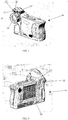
Figures 1 and 2 are front and rear perspective views of a camera suitable for performing the method of the invention. -
Figure 3 shows a block diagram of a representative camera system that can be used to practice embodiments of the invention. -
Figure 4 is a diagram showing the optical path and sensor configuration of the camera. -
Figure 5 shows geometrically, the derivation of the parallax equation. -
Figure 6 shows the (Full-Screen, Full-Sensor infrared)/(Full-Screen, Partial-Sensor Visible-Light) scene display mode. -
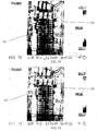
Figure 9 shows combined visible-light and infrared images uncorrected for parallax error. -
Figure 10 shows the same images corrected for parallax error. -
Figures 7 and 8 are cross-sectional views of an infrared camera module with a magnet and Hall-Effect sensor according to an example. -
Figure 12 shows the (Partial-Screen, Partial-Sensor infrared)/(Full-Screen, Full-Sensor Visible-Light) scene display mode. In this mode, the camera uses all of the visible-light sensor elements to fill the display. -
Figure 11 shows the (Partial-Screen, Full-Sensor infrared)/(Full-Screen, Partial-Sensor Visible-Light) scene display mode. In this mode, the camera uses all of the available infrared sensor elements to provide an infrared image that fills only a central area of the camera display. -
Figure 13 shows the (Partial-Screen, Full-Sensor infrared)/(Full-Screen, Full-Sensor Visible-Light) scene display mode. In this mode, the camera uses all of the infrared and all of the visible-light sensor elements to construct the displayed images. -
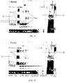
Figures 14-16 show respectively, an infrared only image of an insulated cup, a visible-light only image of the cup and a partial alpha-blended image of the cup. -
Figure 17 shows an example of a "hot threshold" alarm mode display. -
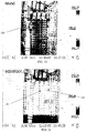
Figure 18 shows a typical infrared image of a low infrared contrast scene. -
Figure 19 shows the same scene with an alpha-blended visible-light image, yielding a much higher apparent contrast. -
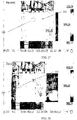
Figures 20-23 show, respectively, a visible-light image with a laser spot, a visible-light image with the laser spot and a computer generated laser marker aligned with the laser spot, an infrared only image with the computer generated laser marker and hot spot not aligned, and an infrared only image with the computer generated laser marker and hot spot aligned. -
Figures 24-26 show, respectively, a visible-light only image with a laser point, an alpha-blended visible-light/infrared image with a laser point and hot spot not aligned, and an alpha-blended visible-light/ infrared image with a laser point spot aligned. -
Figures 27-28 show, respectively, an infrared only image with a computer generated laser pointer and hot spot not aligned and an infrared only image with the computer generated laser pointer and hot spot aligned. -
Figures 29-30 show, respectively, a visible-light only image with a laser spot and a computer generated laser marker not aligned and a visible-light only image with the laser spot and computer generated laser marker aligned. -
Figures 1 and 2 are perspective views of the front and the back of acamera 10 which can be used for the method of the invention. The housing includes an infrared camera module and a visible-light camera module. In particular, thecamera 10 includes acamera housing 12, a Visible-Light (VL)lens 13, aninfrared lens 14,focus ring 16 and alaser pointer 18 as well as various electronics located within the housing as will be described with reference toFigure 3 . In an embodiment, an LED torch/flash 17 is located on each side of theVL lens 13 to aid in providing enough light in dark environments. Adisplay 20 is located on the back of the camera so that infrared images, visible light images and/or blended images of Infrared and Visible-Light may be viewed. In addition, target site temperature (including temperature measurement spot size) and distance readings may be displayed. Also located on the back of the camera areuser controls 22 to control the display mode and activate or deactivate the laser pointer. -
Figure 3 shows a block diagram of a representative camera system that can be used to practice embodiments of the invention.
The Visible-Light camera module includes a CMOS, CCD or other types of visible-light camera, LED torch/flash and a laser pointer. This camera streams RGB image display data (e.g. 30 Hz) to the FPGA for combination with infrared RGB image data and then sends the combined image data to the display.
The Analog Engine interfaces with and controls the infrared sensor, and streams raw infrared image data (e.g. 30 Hz) to the DSP. The DSP performs computations to convert the raw infrared image data to scene temperatures, and then to RGB colors corresponding to the scene temperatures and selected color palette. For example,U.S. Patent No. 6,444,983 entitled "Microbolometer Focal Plane Array With Controlled Bias," assigned to the present assignee, discloses such an infrared camera. The DSP then streams the resulting infrared RGB image display data to the FPGA where it is combined with the VL RGB image data and then sends the combined image data to the display.
The Embedded Processor Card Engine includes a general-purpose microprocessor that provides a graphical user interface (GUI) to the camera operator. This GUI interface consists of menus, text, and graphical display elements that are sent to the FPGA, where they are buffered in SRAM and then sent to the display. - The MSP430 interfaces with the user interface including camera buttons, mouse, LCD backlight, and the smart battery. It reads these inputs and provides the information to the embedded processor card engine where it is used to control the GUI and provides other system control functions.
The FPGA drives the display(s) (LCD and/or TV, for example) with combined visible-light image data, infrared image data, and GUI data. The FPGA requests both the visible-light and infrared image data from the VL and infrared camera modules and alpha-blends them together. It also alpha-blends the resulting display image with the GUI data to create a final blended image that is sent to the LCD display. Of course the display associated with the embodiments of the invention is not limited to an LCD-type display. The FPGA operates under control of the DSP, which is further controlled by the embedded processor card engine. The degree of image alpha-blending and the display mode, i.e. picture-in-a-picture, full screen, color alarm and zoom mode, is controlled by the user through the GUI. These settings are sent from the embedded processor card engine to the DSP which then configures the FPGA properly. - The method of the invention is applicable to a camera that combines an engine of a real-time visible-light camera with an engine of a real-time infrared camera close to each other in the same housing such that the optical axes are roughly parallel to each other.
- The camera according to examples places the engine or module of a real-time visible-light camera in the housing of a real-time infrared camera. The placement is such that the visible and infrared optical axes are as close as practical and roughly parallel to each other, for example, in the vertical plane of the infrared optical axis. Of course other spatial arrangements are possible. The visible light camera module, i.e., VL optics and VL sensor array, are chosen to have a larger field of view (FOV) than the infrared camera module.
Figure 4 is a diagram showing the optical path and sensor configuration of the camera. As shown in the diagram, there are two distinct optical paths and two separate sensors. One for visible-light, and one for infrared. Because the optical paths for the sensors are different, each sensor will "see" the target scene from slightly different vantage points thereby resulting in parallax error. As will be described in detail hereinafter, the parallax error is corrected electronically using software manipulations. This provides the capability to electronically correct the displayed images for parallax. In certain examples, the visible-light optics and sensor are chosen so that their respective field of views (FOV) are different, i.e. one is larger than the other. For instance, in one embodiment, the VL FOV is greater than the infrared FOV. This provides cost effectiveness. Presently, for a given number of pixel sensors, visible light sensor arrays are much cheaper than infrared sensor arrays. Accordingly, for a given field of view and resolution (instantaneous field of view), visible light sensor arrays are cheaper than infrared sensor arrays. - The visible light optics are such that the visible light camera module remains in focus at all usable distances. Only the infrared lens needs focus adjustment for targets at different distances.
-
Figure 5 shows geometrically, the derivation of the parallax equation. As can be seen, parallax can be reduced by minimizing the distance (q) between the visible-light and infrared optical apertures, and also by choosing short focal length lenses. The camera design will typically physically fix (q). In certain examples, the focal lengths of the visible-light and infrared lens (f) can be altered in the field by changing lenses, or using optical systems that include multiple focal lengths or continuous zoom. In the examples with fixed focal length lenses, the focal lengths remain constant during operation once the lenses are installed. Hence, during camera operation, parallax is simply a function of distance (d) to the target. In the example shown, the focal length (f) of each lens is the same. In alternate examples, the focal lengths (f) of the infrared lens and the visible lens may differ from each other.
The camera corrects the visible-light and infrared images for parallax and provides several different methods to display the registered images to the operator. These methods are described below. In general, parallax error corrections are based on the infrared focus distance as will be described hereinafter. - The camera according to the examples can operate in one of three display modes; 1) full screen visible, infrared and/or blended, 2) picture-in-a-picture such as partial infrared image in a full screen visible image, and 3) infrared color alarms in visible-light images. In any one of these display modes, temperatures will be recorded and can be displayed in the infrared portion of the image. Temperatures can also be displayed on a visible-light only image from the recorded but not displayed infrared image.
In the full screen display mode, an operator has a choice of selecting for display a full screen visible-light only image, a full screen infrared only image, or a full screen blend of visible-light and infrared images. In an embodiment of the invention, the display is about 320 by 240 pixels and is represented by the dashed-line box shown inFigure 6 . The infrared sensor has 160 by 120 pixels and the visible-light sensor has 1280 by 1024 pixels. These particular dimensions are given by way of example and are not limiting. Thus, the infrared sensor, the VL sensor and display may each be individually larger or smaller than the particular examples given.Figure 6 shows a diagram of the mode where the full 160 by 120 infrared image is interpolated to fill the camera display. Based on the display mode chosen, a portion of the 1280 by 1024 visible-light image is windowed to match the infrared window. Since the number of selected visible-light sensor elements does not necessarily match the 320 by 240 pixels of the camera display, the visible-light image is scaled to match the camera display. After parallax error correction, each resulting infrared display pixel will represent the same instantaneous field of view (IFOV) as its corresponding visible-light display pixel. Because the two images are matched, the camera operator can easily identify points-of-interest in the infrared image with objects in the visible-light image simply by noting where the features of interest overlie each other in the two images. InFigure 6 , the display mode is entitled "Full-Screen, Full-Sensor Infrared and Full-Screen, Partial-Sensor Visible-Light display mode." Additional display modes are discussed further below.
Parallax error between the visible-light image and the infrared image is corrected automatically by the camera. This process is referred to as registering. In order to apply the proper parallax correction, the camera must first determine the distance to the target object of interest. One method to determine the target distance is to sense the focus position of the infrared lens using a Hall-Effect sensor.Figures 7 and 8 show a sectional view ofcamera 10 taken from front to rear through the center ofinfrared lens 14. Referring toFigs. 7 and 8 , a Hall-Effect sensor 30 is fixed in thehousing 32 with respect to theinfrared sensor array 34 to sense the proximity of amagnet 36 attached to the back of theIR lens 14. As the focus of the lens is changed via rotation offocus ring 16, the distance f ' between themagnet 36 and the Hall-Effect sensor 30 changes, resulting in an output from the Hall-Effect sensor that is proportional to focus position. (The focus of the lens could be changed by moving the lens or moving the infrared sensor array.) This focus position is used to derive an estimate of the distance to the target. The infrared lens focus position provides an especially convenient estimate of distance because typical infrared lenses have a low F-number, resulting in a shallow depth of field. The Hall-Effect sensor may, in one example, be fixed on the infrared sensor array. In addition, the positions of the Hall-Effect sensor and magnet may be reversed from that shown. - In the example shown in
Figs. 7 and 8 , themagnet 36 is a ring that encircles an interior surface of thefocus ring 16 facing theinfrared sensor array 34. The Hall-Effect sensor 30 is fixed in the camera housing 32 a small distance from of theinfrared sensor array 34. The distance between the Hall-Effect sensor and the magnet represents the distance f' shown inFigs 7 and 8. Figure 7 shows the lens positioned for near focus andFigure 8 shows the lens positioned for far focus in which case the magnet is closer to the Hall-Effect sensor than inFigure 7 . Mechanisms and methods other than those described above for a Hall-Effect sensor may, of course, be employed to determine the distance to target. Such equivalent mechanisms or methods would be known to those with skill in the art. The Hall-Effect sensor is one convenient method.
Estimating the distance between the target and the camera is a valuable safety feature. For example, OSHA has specific safety distance requirements when inspecting high voltage electrical cabinets. Thus, using the camera according to the examples, one can display the distance to the target on the display so that the camera operator is assisted in complying with OSHA's safety requirements.
In addition, it can be valuable to know the size of the spot on the target that is being measured (instantaneous field of view spot size). Because the spot size is a function of distance and the camera has the ability to measure (or rather estimate) distance that is needed to correct parallax error, spot size can be calculated as a function of distance and displayed to the camera operator via the display.
The lens position sensor value to focus distance correlation for each infrared lens is determined at the factory and stored with other camera calibration data in the camera's nonvolatile memory. This calibration data includes X and Y image offsets calculated for each focus distance. By utilizing the sensed infrared lens focus position and the factory calibration data, the correct X and Y sensor offsets of the partial area from the visible-light sensor to be displayed can be computed and used to select the appropriate visible-light sensor area for the current infrared focus distance. That is, as the focus distance of the infrared lens is changed, different areas of the visible-light sensor image are extracted and displayed, resulting in registration of the infrared and visible-light images for objects at the focus distance.Figure 9 shows combined picture-in-a-picture display of visible-light and infrared images misaligned, i.e. uncorrected for parallax error.Figure 10 shows the same images corrected for parallax error. Referring toFigure 9 . the center quarter of the display shows a blurry (unfocused) and unregistered infrared-only image 40 placed within the surrounding framework of a visible onlyimage 42. The rectangulardark sections 44 in the image are misaligned (unregistered) showing the parallax error resulting from the unfocusedinfrared image 44. Referring toFigure 10 , the rectangulardark sections 44 in theinfrared image 40 are registered with the portions ofsuch sections 44 in the visible onlyimage 42, showing that infrared image is now properly focused.Figures 9 and 10 highlight a method by which a user ofcamera 10 could focus theinfrared image 40 by merely rotatingfocus ring 16 untilimage 40 is properly registered. AlthoughFigures 9 and 10 show the center quarter of the display as infrared only, this same method and technique could be used for a blended visible and infrared image, whether the images are shown picture in picture, full display, alarm mode, or other display modes.
Note that objects within the scene that are not at the focus distance will still exhibit a parallax error. Nearer objects will exhibit a larger parallax error than objects beyond the focus distance. In practice, parallax error becomes negligible beyond a focus distance of approximately 2.4 meter (8 feet) for lenses used with typical infrared cameras. Also note that parallax errors can only be corrected down to a limited close focus distance to the camera (typically about 0.6 meter (2 feet)). This distance is determined by how much "extra" field of view the visible-light sensor provides as compared to the infrared sensor.
When an image is captured, the full visible-light image and the full infrared image with all of the ancillary data are saved in an image file on the camera memory card. That part of the visible-light image not displayed which lies outside of the camera display dimensions when the image was taken is saved as part of the visible-light image. Later, if an adjustment in the registration between the infrared and visible-light image is needed, either in the camera or on a computer, the full visible-light image is available. - The camera allows the operator to adjust the registration of the visible-light and infrared image after an infrared/Visible-light image pair is captured and stored in memory. One way to accomplish this is to use the infrared lens position as an input control. This allows the operator to fine-tune the registration, or to manually register objects in the scene that were not at the infrared focus distance when the images were captured, simply by rotating the focus ring on the lens.
- The visible-light image, when it is the only displayed image, is displayed preferably in color, although it need not be. When it is blended with the infrared image, the visible-light image is converted to gray scale before it is blended so that it only adds intensity to the colored infrared image.
-
Figure 11 shows the scene display mode entitled "Partial-Screen, Full-Sensor Infrared and Full-Screen, Partial-Sensor Visible-Light display mode." In this mode, the camera uses all of the available infrared sensor elements to provide an infrared image that fills only a central area of the camera display. Standard image processing techniques (e.g. scaling and windowing, for example) are used to fit the infrared image into the desired area of the display. The IFOV of the visible-light image is adjusted to match the IFOV of the infrared image and then a portion of the visible-light image is selected to fill the full display and to match the infrared image in the center of the display. The center quarter of the display can be infrared only, visible-light only or a blend of the two. The remaining three-quarters of the display (outer framework) is visible-light only. - The camera uses the same technique in this mode as that described for the full screen mode to correct for parallax.
- Alternatively, instead of matching the visible-light image to the infrared image just the opposite may be done.
Figures 12 and13 illustrate this technique.Figure 12 shows a picture-in-a-picture "Partial-Screen, Partial-Sensor infrared and Full-Screen, Full-Sensor Visible-Light scene display mode." In this mode, the camera uses all of the visible-light sensor elements to fill the display. If the number of visible-light sensor elements does not match the number of display pixels, the camera uses standard imaging techniques to create an image that fills the display screen. A portion of the available infrared sensors is chosen to provide the infrared image. The infrared image is windowed and matched so that the resulting infrared display pixels provide the same IFOV as the visible-light image display pixels. - The camera uses similar techniques to those described for
Figure 6 to correct for parallax. However, in this mode, different areas of the infrared sensor are selected to match the center region of the visible-light image as the infrared focus distance is changed. Note that in this mode, the infrared image is always displayed in a fixed position in the middle of the display. -
Figure 13 shows the "Partial-Screen, Full-Sensor infrared and Full-Screen, Full-Sensor Visible-Light scene display mode." In this mode, the camera uses all of the infrared and all of the visible-light sensor elements to construct the displayed images. The visible-light image is scaled to completely fill the display. The infrared image is windowed and scaled so that the IFOV of the resulting display pixels match the visible-light image. The resulting image is displayed over the matching area of the visible-light image. - Like the previously described mode, parallax is corrected by moving the infrared image scene to align it with the visible-light image scene.
- Alpha-blending is a process of ratioing the transparency/opaqueness of two images superimposed on one pixel. If the Alpha = maximum, then the first image is opaque and the second is transparent and is so written to the display. If Alpha = 0, then the first image is transparent and the second image is opaque and is so written to the display. Values in-between cause 'blending' (alpha blending) between the two sources, with the formula Display =
Source 1*(Alpha/max_Alpha) + Source 2*((max_Alpha-Alpha)/max_Alpha). -
Figures 14-16 , show respectively, an infrared only image of an insulated cup, a visible light (VL) only image of the cup, and a partial alpha-blending of the infrared and VL images. - The camera will enable the operator to adjust the alpha blending of the visible and infrared images from the extremes of infrared-only (
Fig. 14 ) or visible-only (Fig. 15 ) to any combination of alpha blending between these two extremes (Fig. 16 ). Note that although the infrared image is not visible inFigure 15 , the underlying infrared image data is used to display thecorrect object temperature 52 in the visible light image. Thus, as the cursor is moved over the visible-light image, thetemperature 52 associated with the cursor's location on the image is displayed. - The infrared and visible-light images can be displayed in either color or grayscale. When color is used to portray temperatures in the infrared image, the visible image in the overlap area can be displayed in grayscale only so that it doesn't excessively corrupt the infrared palette colors.
- When an image is saved, both the visible and infrared images are saved individually so reconstructing images with different alpha blending can be accomplished later either in the camera, or with PC software.
- The camera supports several different visual alarm modes. These modes are used to call the operator's attention to areas of interest in the visible-light image by displaying an alpha-blended or infrared only image in areas that meet the alarm criteria as set by the user.
Figure 17 shows an example of the "hot threshold" alarm mode. Only those pixels in the infrared image that exceed a set temperature threshold (hotspots 60) are displayed. In the color alarm mode, the visible-light image 62 is switched to gray scale so that the infrared image stands out with no ambiguity. The camera can provide alarm modes, such as those described below. Other alarm modes are also possible. - Absolute hot threshold - infrared pixels above a defined temperature are alpha-blended with corresponding visible-image pixels.
- Absolute cold threshold - infrared pixels below a defined temperature are alpha-blended with corresponding visible-image pixels.
- Relative hot threshold - A temperature range is defined by the user. The temperature range is relative to the current hottest pixel (or average of a set number of hottest pixels) in the scene or from a previous scene or reference scene. Infrared pixels above the threshold defined by the current hottest pixel(s) in the scene minus a user defined or predetermined temperature range are alpha-blended with their corresponding visible-image pixels. For example, if the temperature range is 5 degrees, and the current hottest pixel(s) in the scene is 100 degrees, for example, all infrared pixels above 95 degrees in the scene will be alpha-blended with corresponding visible-light pixels.
- Relative cold threshold - A temperature range is defined by the user. The temperature range is relative to the current coldest pixel (or average of a set number of coldest pixels) in the scene or from a previous scene or reference scene. Infrared pixels below the threshold defined by the current coldest pixel(s) in the scene plus a user defined or predetermined temperature range are alpha-blended with their corresponding visible-image pixels. For example, if the temperature range is 5 degrees, and the current coldest pixel(s) in the scene is 10 degrees, all infrared pixels below 15 degrees in the scene will be alpha-blended with corresponding visible-light pixels.
- Absolute range (isotherm) - The operator enters a temperature range. Infrared pixels with a temperature within the set range are alpha-blended with their corresponding visible-light pixels. For example, the user enters a range of 80-100 degrees. All infrared pixels with a temperature value within the 80-100 degree range are alpha-blended.
- Alarm flash mode - To further call attention to areas of interest, the camera may provide a mode whereby the alpha-blended areas are "flashed" by alternately displaying the alarmed pixels as visible-light only, and then either alpha-blended or infrared only.
- The alarm modes identified above may also be indicated audibly or via vibration. Such audible or vibrational alarms may be useful in situations where hotspots are small enough to otherwise go unnoticed in the visual display. In embodiments that include audible or vibration alarms, the camera can generate such an alarm to alert the camera operator when, for instance, the camera detects an out of specification temperature or any of the other alarms modes identified above. Referring back to
Figure 3 , the camera may include an alarm module connected to the FPGA that provides audible or vibrational alarms. The vibration mechanism can be similar to that used in cellular phones to alert persons of an incoming call. - All of the image display techniques described for the camera can also be implemented in software that runs on a PC host computer and can be applied to images captured by the camera.
- The advantages have already been stated above. The infrared image will not only be sharper with much more detail, it will be surrounded with a visual image showing exactly what and where the infrared targets are. Parallax error will be automatically corrected, yielding a visible-light control image that is correctly registered with the infrared image. Infrared cameras can be made with smaller less expensive detector arrays, yet display the apparent detail and contrast of very expensive infrared cameras with large and ultra-sensitive detector arrays.
Figure 18 shows a typical infrared image of a low infrared contrast scene.Figure 19 shows the same scene with an alpha-blended visible-light image, yielding a much higher apparent contrast with target site temperature measurement. - This camera can be used in all phases of infrared thermography where current infrared cameras are used today and in the future. In the case of the simplest uses such as an electricians tool, the camera can be made inexpensively with a small infrared detector array and yet have very high performance -- high image quality with high spatial resolution and accurate temperature. In the case of high-end thermography the camera can be made at a lower cost and have images with greater apparent detail than the most expensive infrared cameras. The camera will eliminate the need to take separate visible-light images to be included in thermography reports.
- Various applications are possible using the laser examples. As previously mentioned, because the laser pointer radiation is in the visible spectrum, it is not visible in the infrared image. As a result, the laser pointer is of limited value in infrared cameras. This is problematic when the location of a hot or cold spot is difficult to identify. For example, large industrial control panels often have many components that are similar in shape and packed tightly together. It is sometimes difficult to determine the exact component that is causing a hot spot in the infrared camera image. In addition, in building inspection applications where a wall appears uniform in the visible image but shows a defect in the infrared image, the laser pointer of the example can be used to identify the exact location of the defect on the wall. For roof leak detection applications, it can greatly aid the thermographer in marking the area suspected of needing repair. The camera operator can outline the wet area by adjusting the camera pointing so that the laser spot seen in the image outlines the suspected wet area in the image and thus also outlines the suspected wet area on the roof with the laser beam so that it can be correctly marked. In an R&D application where the target is complex such as a printed wiring board assembly, the laser pointer example may aid in identifying the location of the infrared point of interest.
- The laser pointer of the example is used to accurately identify the location of infrared points-of-interest and to easily aid the focusing of the infrared optics.
Figures 24-26 show an associated sequence of events. The laser pointer can be turned on using one of the camera's programmable buttons or by other mechanisms by the camera operator. At a reasonable distance, thelaser pointer spot 100 on the target can be seen in the visible-light image (Fig. 24 ) and in the blended visible-light and infrared image that has been corrected for parallax error (Fig. 25 ). Once the laser spot is identified in the blended image (Fig. 25 ), the camera operator can adjust the camera pointing until the laser spot in the blended image matches the spot ofinterest 102 in the infrared image (Fig. 26 ). The laser beam then marks the target at the point-of-interest (Fig. 26 ). - Because the camera according to the example has been calibrated in the factory to identify the location of the laser spot in the infrared image using parallax calibration data as a function of infrared camera module focus distance, the camera operator does not need to see displayed the laser spot in the VL image. If the target is at a distance and/or has a low reflection for the laser wavelength, the laser spot may be too weak for the VL camera to show prominently on the camera display but it can still be seen on the target by the human observer.
Figures 27 and 28 show an associated sequence of events. In this case, the infrared focus is adjusted as normally done by observing the sharpness of the infrared image. A computer-generated laserspot reference mark 200 is registered with the infrared image so that a representative mark (e.g., circle) is displayed on the infrared image (Fig. 27 ). The camera operator then adjusts the camera pointing until thelaser calibration mark 200 lies over the infrared point-of-interest 202 (Fig. 28 ). Once that happens, the laser beam then strikes the target at the point of interest. - Alternatively, the camera operator first focuses the infrared image using an infrared display image only, switches to the visible-light display where the
laser 210 will be shown in the display as seen inFigure 20 . The operator marks thelaser spot 210 on the display with a marking 212 such as a circle (seeFigure 21 ) and then switches the display back to the infrared only (seeFigure 22 ) where the marking 212 is registered with the infrared image and it is displayed on the infrared image, positioned in the center quarter of the display area. The operator then adjusts the camera pointing so that themark 212 on the infrared display matches the thermal spot ofinterest 214 on the infrared display, (seeFigure 23 ) Once that happens, the laser beam then strikes the target at the point of interest. - With calibration data correcting for parallax between the laser pointer and the infrared image and the ability to see the actual laser spot in the VL image, a process for monitoring and aiding the infrared focus is possible.
Figures 29 and 30 show an associated sequence of events. In this case, the location of thelaser spot 220 is visible in the VL image (Fig. 29 ). The camera according to the example has been calibrated in the factory to generate a computer-generated laserspot reference mark 222 that indicates the location of the laser spot in a focused infrared image using parallax calibration data as a function of infrared camera module focus distance. This reference mark may be displayed in the IR image or the VL image (that overlaps the IR image). InFigure 29 , thereference mark 222 is shown in the VL only image. As the infrared lens is adjusted, the mark moves in the VL image showing the spot where the laser dot would be in the infrared image. When the infrared mark is coincident with the laser dot seen in the VL image (Fig. 30 ), the focus adjustment may stop and the infrared camera module is in focus. This allows the most novice operator to focus the infrared lens and eliminates the subjective nature of focusing.
Claims (11)
- A method of displaying and registering visible-light (VL) images and infrared (IR) images of a target, the method comprising:providing a camera (10) having a VL camera module comprising visible light optics such that the VL camera module remains in focus at all usable distances, an IR camera module and a display (20), the VL camera module having a first field of view (FOV), the IR camera module having a second FOV different from the first FOV causing a parallax error, the VL camera module producing a first image of the first FOV, the IR camera module producing a second image of the second FOV, and wherein a sensor is mounted within a manual focus mechanism in the IR camera module for determining the distance from the IR camera module to the target in focus;displaying at least portions of the first and second images from the VL camera module and the IR camera module on the display (20);providing calibration data including first and second image offsets calculated for each focus distance of the manual focus mechanism in the IR camera module;registering the images from the VL camera module and IR camera module on the display (20) by displacing the images from the VL camera module and the IR camera module relative to each other in accordance with the calibration data until registered by changing the focus distance of the manual focus mechanism in the IR camera module.
- The method of claim 1, wherein the at least portions of the image from the IR camera module is displayed generally centrally within the at least portions of the image from the VL camera module.
- The method of claim 1, wherein the at least portions of the image from the IR camera module is displayed alpha-blended with the at least portions of the image from the VL camera module.
- The method of claim 1, wherein the at least portions of the image from the IR camera module is displayed without the image from the VL camera module on a portion of the display.
- The method of claim 1, further including determining a value indicative of the distance between the IR camera module and the target.
- The method of claim 1 or claim 5, wherein changing the focus distance of the manual focus mechanism in the IR camera module comprises moving a lens of the IR camera module with respect to a sensor array of the IR camera module.
- The method of claim 6, wherein the sensor array comprising 160 pixels by 120 pixels.
- The method of any one of the preceding claims, wherein the VL camera module, the IR camera module, and the display are mounted in a camera housing.
- A computer-readable medium programmed with instructions for performing a method of displaying and registering images from multiple camera modules, the medium comprising instructions for causing a programmable processor to:receive a first image that includes a target from a visible light (VL) camera module, the VL camera module comprising visible light optics such that the VL camera module remains in focus at all usable distances,the VL camera module having a first field of view (FOV);receive a second image that includes the target from an infrared camera (IR) module, the infrared camera module having a second FOV;determining the distance from the IR camera module to the target, wherein the distance from the IR camera module to the target is determined by focusing the second FOV, wherein a sensor mounted within a manual focus mechanism in the IR camera module provides data indicating the distance from the IR camera module to the target;receiving calibration data including first and second image offsets calculated for each focus distance of the manual focus mechanism in the IR camera module;correcting a parallax error using the determined distance and the received calibration data to register the first and second images; anddisplaying at least portions of the first and second images on a display with the portions of the first and second images registered.
- The method of claim 9, further comprising displaying on the display the determined distance between the at least one of the camera modules and the target.
- The method of claim 9 or claim 10, further comprising determining and displaying the instantaneous field of view spot size of the at least portions of the first and second images being displayed.
Applications Claiming Priority (2)
| Application Number | Priority Date | Filing Date | Title |
|---|---|---|---|
| US63307804P | 2004-12-03 | 2004-12-03 | |
| PCT/US2005/043825 WO2006060746A2 (en) | 2004-12-03 | 2005-12-05 | Visible light and ir combined image camera with a laser pointer |
Publications (3)
| Publication Number | Publication Date |
|---|---|
| EP1831657A2 EP1831657A2 (en) | 2007-09-12 |
| EP1831657A4 EP1831657A4 (en) | 2012-11-21 |
| EP1831657B1 true EP1831657B1 (en) | 2018-12-05 |
Family
ID=36565823
Family Applications (1)
| Application Number | Title | Priority Date | Filing Date |
|---|---|---|---|
| EP05852909.0A Active EP1831657B1 (en) | 2004-12-03 | 2005-12-05 | Method for a visible light and ir combined image camera |
Country Status (4)
| Country | Link |
|---|---|
| US (3) | US7538326B2 (en) |
| EP (1) | EP1831657B1 (en) |
| CN (1) | CN101111748B (en) |
| WO (1) | WO2006060746A2 (en) |
Families Citing this family (304)
| Publication number | Priority date | Publication date | Assignee | Title |
|---|---|---|---|---|
| US20060078037A1 (en) * | 2003-04-16 | 2006-04-13 | Tzong-Sheng Lee | Thermometer with image display |
| US8705808B2 (en) * | 2003-09-05 | 2014-04-22 | Honeywell International Inc. | Combined face and iris recognition system |
| US8090157B2 (en) | 2005-01-26 | 2012-01-03 | Honeywell International Inc. | Approaches and apparatus for eye detection in a digital image |
| US8442276B2 (en) | 2006-03-03 | 2013-05-14 | Honeywell International Inc. | Invariant radial iris segmentation |
| US7593550B2 (en) | 2005-01-26 | 2009-09-22 | Honeywell International Inc. | Distance iris recognition |
| US8049812B2 (en) * | 2006-03-03 | 2011-11-01 | Honeywell International Inc. | Camera with auto focus capability |
| US8098901B2 (en) | 2005-01-26 | 2012-01-17 | Honeywell International Inc. | Standoff iris recognition system |
| US8064647B2 (en) | 2006-03-03 | 2011-11-22 | Honeywell International Inc. | System for iris detection tracking and recognition at a distance |
| US20080267253A1 (en) * | 2004-04-14 | 2008-10-30 | Baraldi Chemgroup Srl | Method to Optimise Temperature Regulation in Technological Processes |
| US8531562B2 (en) * | 2004-12-03 | 2013-09-10 | Fluke Corporation | Visible light and IR combined image camera with a laser pointer |
| DE102005006290A1 (en) * | 2005-02-11 | 2006-08-24 | Bayerische Motoren Werke Ag | Method and device for visualizing the surroundings of a vehicle by fusion of an infrared and a visual image |
| US8253619B2 (en) | 2005-02-15 | 2012-08-28 | Techtronic Power Tools Technology Limited | Electromagnetic scanning imager |
| AU2006345002B2 (en) * | 2005-07-27 | 2012-02-02 | L-3 Communications Cyterra Corporation | Energetic material detector |
| US8292496B1 (en) | 2005-07-27 | 2012-10-23 | L-3 Communications Cyterra Corporation | Energetic material detector |
| US7732768B1 (en) * | 2006-03-02 | 2010-06-08 | Thermoteknix Systems Ltd. | Image alignment and trend analysis features for an infrared imaging system |
| GB2450024B (en) * | 2006-03-03 | 2011-07-27 | Honeywell Int Inc | Modular biometrics collection system architecture |
| JP4738488B2 (en) | 2006-03-03 | 2011-08-03 | ハネウェル・インターナショナル・インコーポレーテッド | Iris recognition system with image quality metric |
| KR101299074B1 (en) | 2006-03-03 | 2013-08-30 | 허니웰 인터내셔널 인코포레이티드 | Iris encoding system |
| CN101496387B (en) | 2006-03-06 | 2012-09-05 | 思科技术公司 | System and method for access authentication in a mobile wireless network |
| JP4333685B2 (en) * | 2006-03-29 | 2009-09-16 | セイコーエプソン株式会社 | Camera, image display method and program thereof |
| JP4885612B2 (en) * | 2006-05-16 | 2012-02-29 | 日置電機株式会社 | thermometer |
| US8130261B2 (en) * | 2006-10-10 | 2012-03-06 | Exelis, Inc. | System and method for dynamically correcting parallax in head borne video systems |
| US8289372B2 (en) * | 2006-10-16 | 2012-10-16 | Flir Systems Ab | Method for displaying a thermal image in an IR camera and an IR camera |
| US9191583B2 (en) | 2006-10-16 | 2015-11-17 | Flir Systems Ab | Method for displaying a thermal image in an IR camera, and an IR camera |
| JP4949806B2 (en) * | 2006-11-10 | 2012-06-13 | オンセミコンダクター・トレーディング・リミテッド | Imaging apparatus and image signal processing apparatus |
| US20080170033A1 (en) * | 2007-01-15 | 2008-07-17 | International Business Machines Corporation | Virtual pointer |
| US20080224041A1 (en) * | 2007-03-16 | 2008-09-18 | Cannamela John J | Method and apparatus for subsurface anomaly detection and image projection |
| US8063889B2 (en) | 2007-04-25 | 2011-11-22 | Honeywell International Inc. | Biometric data collection system |
| US7544944B2 (en) * | 2007-07-02 | 2009-06-09 | Flir Systems Ab | Camera and method for use with camera |
| US7809258B2 (en) | 2007-07-06 | 2010-10-05 | Flir Systems Ab | Camera and method for use with camera |
| US7826736B2 (en) | 2007-07-06 | 2010-11-02 | Flir Systems Ab | Camera and method for use with camera |
| US8089694B2 (en) * | 2007-08-24 | 2012-01-03 | Sony Ericsson Mobile Communications Ab | Optical device stabilizer |
| US8208759B2 (en) * | 2007-08-29 | 2012-06-26 | Texas Instruments Incorporated | Light valve projection of visible image correlated with non-visible image |
| US8289377B1 (en) * | 2007-08-31 | 2012-10-16 | DigitalOptics Corporation MEMS | Video mode hidden autofocus |
| US7820967B2 (en) * | 2007-09-11 | 2010-10-26 | Electrophysics Corp. | Infrared camera for locating a target using at least one shaped light source |
| US8044991B2 (en) * | 2007-09-28 | 2011-10-25 | The Boeing Company | Local positioning system and method |
| US8374438B1 (en) * | 2007-10-04 | 2013-02-12 | Redshift Systems Corporation | Visual template-based thermal inspection system |
| US20090092283A1 (en) * | 2007-10-09 | 2009-04-09 | Honeywell International Inc. | Surveillance and monitoring system |
| US8102424B2 (en) | 2007-10-17 | 2012-01-24 | Fluke Corporation | Ergonomic configurations for thermal imaging cameras |
| US8212210B2 (en) * | 2008-02-04 | 2012-07-03 | Flir Systems Ab | IR camera and method for presenting IR information |
| US8797377B2 (en) | 2008-02-14 | 2014-08-05 | Cisco Technology, Inc. | Method and system for videoconference configuration |
| US7667198B2 (en) * | 2008-04-02 | 2010-02-23 | Flir Systems Ab | IR camera and a method for processing information in images |
| WO2009126710A2 (en) * | 2008-04-10 | 2009-10-15 | Perceptive Pixel, Inc. | Methods of interfacing with multi-input devices and multi-input display systems employing interfacing techniques |
| US8390667B2 (en) | 2008-04-15 | 2013-03-05 | Cisco Technology, Inc. | Pop-up PIP for people not in picture |
| US20090262012A1 (en) * | 2008-04-16 | 2009-10-22 | Paul Carlson | Radiometer and temperature compensation system |
| US8436907B2 (en) | 2008-05-09 | 2013-05-07 | Honeywell International Inc. | Heterogeneous video capturing system |
| US11792538B2 (en) | 2008-05-20 | 2023-10-17 | Adeia Imaging Llc | Capturing and processing of images including occlusions focused on an image sensor by a lens stack array |
| EP3328048B1 (en) | 2008-05-20 | 2021-04-21 | FotoNation Limited | Capturing and processing of images using monolithic camera array with heterogeneous imagers |
| US8866920B2 (en) | 2008-05-20 | 2014-10-21 | Pelican Imaging Corporation | Capturing and processing of images using monolithic camera array with heterogeneous imagers |
| US8213782B2 (en) * | 2008-08-07 | 2012-07-03 | Honeywell International Inc. | Predictive autofocusing system |
| US8090246B2 (en) | 2008-08-08 | 2012-01-03 | Honeywell International Inc. | Image acquisition system |
| US8235590B2 (en) * | 2008-08-21 | 2012-08-07 | Fluke Corporation | Thermal instrument engine |
| US7924312B2 (en) * | 2008-08-22 | 2011-04-12 | Fluke Corporation | Infrared and visible-light image registration |
| DE102008046963A1 (en) * | 2008-09-12 | 2010-06-10 | Siemens Aktiengesellschaft | Image recording unit for fusion of image of e.g. building, has signal processing unit receiving data processing signals from optical units, where signals are converted into signals of heat image based on visible image using preset formula |
| US8306279B2 (en) * | 2008-09-15 | 2012-11-06 | Eyelock, Inc. | Operator interface for face and iris recognition devices |
| US8694658B2 (en) | 2008-09-19 | 2014-04-08 | Cisco Technology, Inc. | System and method for enabling communication sessions in a network environment |
| JP5399674B2 (en) * | 2008-09-26 | 2014-01-29 | テルモ株式会社 | Infrared thermography apparatus and image processing method |
| JP2010103740A (en) * | 2008-10-23 | 2010-05-06 | Panasonic Corp | Digital camera |
| US7652251B1 (en) | 2008-11-17 | 2010-01-26 | Fluke Corporation | Registration methods for fusing corresponding infrared and visible light images |
| US8280119B2 (en) | 2008-12-05 | 2012-10-02 | Honeywell International Inc. | Iris recognition system using quality metrics |
| EP2683156A3 (en) * | 2008-12-12 | 2015-02-11 | Testo AG | Thermal imaging camera |
| US8595689B2 (en) * | 2008-12-24 | 2013-11-26 | Flir Systems Ab | Executable code in digital image files |
| US8167483B2 (en) * | 2009-01-15 | 2012-05-01 | Fluke Corporation | Temperature measurement instruments and methods for identifying a selected target area |
| JP5399738B2 (en) * | 2009-02-25 | 2014-01-29 | テルモ株式会社 | Infrared thermography device |
| JP5399737B2 (en) * | 2009-02-25 | 2014-01-29 | テルモ株式会社 | Infrared thermography device |
| US9451183B2 (en) * | 2009-03-02 | 2016-09-20 | Flir Systems, Inc. | Time spaced infrared image enhancement |
| US10757308B2 (en) | 2009-03-02 | 2020-08-25 | Flir Systems, Inc. | Techniques for device attachment with dual band imaging sensor |
| US8749635B2 (en) * | 2009-06-03 | 2014-06-10 | Flir Systems, Inc. | Infrared camera systems and methods for dual sensor applications |
| WO2015103448A2 (en) * | 2013-12-31 | 2015-07-09 | Flir Systems, Inc. | Techniques for device attachment with dual band imaging sensor |
| US8659637B2 (en) | 2009-03-09 | 2014-02-25 | Cisco Technology, Inc. | System and method for providing three dimensional video conferencing in a network environment |
| US8063367B2 (en) * | 2009-04-23 | 2011-11-22 | Fluke Corporation | Lens position sensor for infrared cameras |
| US8977528B2 (en) | 2009-04-27 | 2015-03-10 | The Boeing Company | Bonded rework simulation tool |
| US9108738B1 (en) | 2009-05-19 | 2015-08-18 | The Boeing Company | Apparatus for refueling aircraft |
| US8659639B2 (en) | 2009-05-29 | 2014-02-25 | Cisco Technology, Inc. | System and method for extending communications between participants in a conferencing environment |
| US9716843B2 (en) * | 2009-06-03 | 2017-07-25 | Flir Systems, Inc. | Measurement device for electrical installations and related methods |
| US9843743B2 (en) * | 2009-06-03 | 2017-12-12 | Flir Systems, Inc. | Infant monitoring systems and methods using thermal imaging |
| US10091439B2 (en) | 2009-06-03 | 2018-10-02 | Flir Systems, Inc. | Imager with array of multiple infrared imaging modules |
| US10044946B2 (en) | 2009-06-03 | 2018-08-07 | Flir Systems Ab | Facilitating analysis and interpretation of associated visible light and infrared (IR) image information |
| US8472681B2 (en) * | 2009-06-15 | 2013-06-25 | Honeywell International Inc. | Iris and ocular recognition system using trace transforms |
| US8630464B2 (en) * | 2009-06-15 | 2014-01-14 | Honeywell International Inc. | Adaptive iris matching using database indexing |
| US8568545B2 (en) | 2009-06-16 | 2013-10-29 | The Boeing Company | Automated material removal in composite structures |
| CN101945224B (en) * | 2009-07-01 | 2015-03-11 | 弗卢克公司 | Thermography methods |
| US9082297B2 (en) | 2009-08-11 | 2015-07-14 | Cisco Technology, Inc. | System and method for verifying parameters in an audiovisual environment |
| US8384783B2 (en) | 2009-09-29 | 2013-02-26 | Flir Systems Ab | Infrared camera and method for calculating output power value indicative of an amount of energy dissipated in an image view |
| US9159130B2 (en) * | 2009-10-22 | 2015-10-13 | Koninklijke Philips N.V. | Alignment of an ordered stack of images from a specimen |
| EP2502115A4 (en) | 2009-11-20 | 2013-11-06 | Pelican Imaging Corp | Capturing and processing of images using monolithic camera array with heterogeneous imagers |
| US8599264B2 (en) * | 2009-11-20 | 2013-12-03 | Fluke Corporation | Comparison of infrared images |
| US8153971B2 (en) * | 2009-11-23 | 2012-04-10 | Flir Systems Ab | Camera with two visual imaging subsystems for determining parallax and for focusing an IR imaging subsystem |
| US8853631B2 (en) * | 2009-11-23 | 2014-10-07 | Flir Systems Ab | Camera with two visual imaging subsystems for determining parallax and for focusing an infrared imaging subsystem |
| WO2011079208A1 (en) * | 2009-12-24 | 2011-06-30 | Flir Systems, Inc. | Cameras with on-board reporting capabilities |
| US9500555B2 (en) * | 2010-01-19 | 2016-11-22 | Clark Robert Gunness | Method and system for leak detection in roofing and waterproofing membranes |
| US9225916B2 (en) * | 2010-03-18 | 2015-12-29 | Cisco Technology, Inc. | System and method for enhancing video images in a conferencing environment |
| DE102010013377B4 (en) * | 2010-03-30 | 2012-02-02 | Testo Ag | Image processing method and thermal imaging camera |
| US9077915B2 (en) * | 2010-04-07 | 2015-07-07 | Projectiondesign As | Interweaving of IR and visible images |
| US8619167B2 (en) | 2010-04-28 | 2013-12-31 | Microsoft Corporation | Scanned beam display and image capture |
| SG10201503516VA (en) | 2010-05-12 | 2015-06-29 | Pelican Imaging Corp | Architectures for imager arrays and array cameras |
| US9313452B2 (en) | 2010-05-17 | 2016-04-12 | Cisco Technology, Inc. | System and method for providing retracting optics in a video conferencing environment |
| WO2011151803A2 (en) * | 2010-06-03 | 2011-12-08 | Aselsan Elektronik Sanayi Ve Ticaret Anonim Sirketi | An electro-optical detector device |
| US20110316697A1 (en) * | 2010-06-29 | 2011-12-29 | General Electric Company | System and method for monitoring an entity within an area |
| DE102010030928A1 (en) | 2010-07-05 | 2012-01-05 | Robert Bosch Gmbh | Non-contact measurement of a mean surface temperature of a measuring range |
| EP2608713A4 (en) | 2010-08-27 | 2014-01-08 | Milwaukee Electric Tool Corp | Thermal detection systems, methods, and devices |
| US8896655B2 (en) | 2010-08-31 | 2014-11-25 | Cisco Technology, Inc. | System and method for providing depth adaptive video conferencing |
| US8742887B2 (en) | 2010-09-03 | 2014-06-03 | Honeywell International Inc. | Biometric visitor check system |
| US8599934B2 (en) | 2010-09-08 | 2013-12-03 | Cisco Technology, Inc. | System and method for skip coding during video conferencing in a network environment |
| TWI468655B (en) * | 2010-10-07 | 2015-01-11 | Hon Hai Prec Ind Co Ltd | System and method for monitoring temperature |
| US8599865B2 (en) | 2010-10-26 | 2013-12-03 | Cisco Technology, Inc. | System and method for provisioning flows in a mobile network environment |
| US8699457B2 (en) | 2010-11-03 | 2014-04-15 | Cisco Technology, Inc. | System and method for managing flows in a mobile network environment |
| US8730297B2 (en) | 2010-11-15 | 2014-05-20 | Cisco Technology, Inc. | System and method for providing camera functions in a video environment |
| US9143725B2 (en) | 2010-11-15 | 2015-09-22 | Cisco Technology, Inc. | System and method for providing enhanced graphics in a video environment |
| US8902244B2 (en) | 2010-11-15 | 2014-12-02 | Cisco Technology, Inc. | System and method for providing enhanced graphics in a video environment |
| US9338394B2 (en) | 2010-11-15 | 2016-05-10 | Cisco Technology, Inc. | System and method for providing enhanced audio in a video environment |
| WO2012067282A1 (en) | 2010-11-17 | 2012-05-24 | (주)이지템 | Mobile device and method for measuring temperature of thermal picture including body temperature |
| US8542264B2 (en) | 2010-11-18 | 2013-09-24 | Cisco Technology, Inc. | System and method for managing optics in a video environment |
| US8723914B2 (en) | 2010-11-19 | 2014-05-13 | Cisco Technology, Inc. | System and method for providing enhanced video processing in a network environment |
| US9111138B2 (en) | 2010-11-30 | 2015-08-18 | Cisco Technology, Inc. | System and method for gesture interface control |
| US8379123B2 (en) | 2010-12-13 | 2013-02-19 | Research In Motion Limited | System and method of capturing low-light images on a mobile device |
| WO2012081995A1 (en) * | 2010-12-13 | 2012-06-21 | Surveylab Group Limited | Mobile measurement devices, instruments and methods |
| US9952316B2 (en) | 2010-12-13 | 2018-04-24 | Ikegps Group Limited | Mobile measurement devices, instruments and methods |
| CN102128686B (en) * | 2010-12-14 | 2012-11-21 | 天津理工大学 | Infrared microscopic thermodetector |
| US8878950B2 (en) | 2010-12-14 | 2014-11-04 | Pelican Imaging Corporation | Systems and methods for synthesizing high resolution images using super-resolution processes |
| USD682854S1 (en) | 2010-12-16 | 2013-05-21 | Cisco Technology, Inc. | Display screen for graphical user interface |
| US8760509B2 (en) | 2010-12-31 | 2014-06-24 | Fluke Corporation | Thermal imager with non-uniformity correction |
| DE102011010469A1 (en) * | 2011-02-05 | 2012-08-09 | Testo Ag | Method for generating composite image from two individual images for infrared camera, involves determining overlapping regions and/or image transformation rules for registering images in overlapping regions by comparing other images |
| MY165813A (en) * | 2011-02-25 | 2018-04-27 | Photonis Netherlands B V | Acquiring and displaying images in real-time |
| US8692862B2 (en) | 2011-02-28 | 2014-04-08 | Cisco Technology, Inc. | System and method for selection of video data in a video conference environment |
| WO2012125819A2 (en) | 2011-03-15 | 2012-09-20 | Milwaukee Electric Tool Corporation | Thermal imager |
| US8670019B2 (en) | 2011-04-28 | 2014-03-11 | Cisco Technology, Inc. | System and method for providing enhanced eye gaze in a video conferencing environment |
| US8786631B1 (en) | 2011-04-30 | 2014-07-22 | Cisco Technology, Inc. | System and method for transferring transparency information in a video environment |
| US20120284124A1 (en) * | 2011-05-06 | 2012-11-08 | Harangozo Matej | Building energy performance/improvements |
| KR101973822B1 (en) | 2011-05-11 | 2019-04-29 | 포토네이션 케이맨 리미티드 | Systems and methods for transmitting and receiving array camera image data |
| US8934026B2 (en) | 2011-05-12 | 2015-01-13 | Cisco Technology, Inc. | System and method for video coding in a dynamic environment |
| US20120320189A1 (en) | 2011-06-20 | 2012-12-20 | Fluke Corporation | Thermal imager that analyzes temperature measurement calculation accuracy |
| US10965889B2 (en) | 2011-06-20 | 2021-03-30 | Fluke Corporation | Thermal imager that analyzes temperature measurement calculation accuracy |
| US9204062B2 (en) * | 2011-08-24 | 2015-12-01 | Fluke Corporation | Thermal imaging camera with range detection |
| US8902302B2 (en) | 2011-09-16 | 2014-12-02 | Emerson Electric Co. | Method and apparatus for surveying with a feature location |
| WO2013043751A1 (en) | 2011-09-19 | 2013-03-28 | Pelican Imaging Corporation | Systems and methods for controlling aliasing in images captured by an array camera for use in super resolution processing using pixel apertures |
| IN2014CN02708A (en) | 2011-09-28 | 2015-08-07 | Pelican Imaging Corp | |
| US8947493B2 (en) | 2011-11-16 | 2015-02-03 | Cisco Technology, Inc. | System and method for alerting a participant in a video conference |
| CN102393561B (en) * | 2011-11-21 | 2015-03-25 | 无锡亮源激光技术有限公司 | Portable laser night vision device |
| US20130155249A1 (en) * | 2011-12-20 | 2013-06-20 | Fluke Corporation | Thermal imaging camera for infrared rephotography |
| US9370668B2 (en) | 2011-12-21 | 2016-06-21 | Best Cure Foundation, Inc. | Apparatus and method to visually view high-dose-radiation apparatus used to verify quality assurance |
| US20130162835A1 (en) * | 2011-12-23 | 2013-06-27 | Fluke Corporation | Thermal imaging camera for infrared rephotography |
| US10230908B2 (en) * | 2012-01-12 | 2019-03-12 | Mission Infrared Electro Optics Technology Co., Ltd | Thermal imaging device and thermal image photographing method |
| CN103105234B (en) * | 2012-01-12 | 2016-05-11 | 杭州美盛红外光电技术有限公司 | Thermal imagery device and thermal imagery specification image pickup method |
| JP2013156109A (en) * | 2012-01-30 | 2013-08-15 | Hitachi Ltd | Distance measurement device |
| TWI535996B (en) * | 2012-02-10 | 2016-06-01 | 鴻海精密工業股份有限公司 | 3d vision system for measuring distance |
| CN103256917B (en) * | 2012-02-15 | 2017-12-12 | 赛恩倍吉科技顾问(深圳)有限公司 | It can be applied to the stereo visual system of ranging |
| WO2013126578A1 (en) | 2012-02-21 | 2013-08-29 | Pelican Imaging Corporation | Systems and methods for the manipulation of captured light field image data |
| EP2634747A1 (en) | 2012-02-29 | 2013-09-04 | Flir Systems AB | A method and system for projecting a visible representation of infrared radiation |
| EP2635022A1 (en) | 2012-02-29 | 2013-09-04 | Flir Systems AB | A method and system for performing alignment of a projection image to detected infrared (IR) radiation information |
| CN104364800A (en) * | 2012-03-30 | 2015-02-18 | 前视红外系统股份公司 | Facilitating analysis and interpretation of associated visible light and infrared (IR) image information |
| US20130258473A1 (en) * | 2012-04-03 | 2013-10-03 | Exelis, Inc | Stowable lens cap for optical device |
| US9538880B2 (en) * | 2012-05-09 | 2017-01-10 | Convotherm Elektrogeraete Gmbh | Optical quality control system |
| WO2014005123A1 (en) | 2012-06-28 | 2014-01-03 | Pelican Imaging Corporation | Systems and methods for detecting defective camera arrays, optic arrays, and sensors |
| US20140002674A1 (en) | 2012-06-30 | 2014-01-02 | Pelican Imaging Corporation | Systems and Methods for Manufacturing Camera Modules Using Active Alignment of Lens Stack Arrays and Sensors |
| EP2873229A1 (en) * | 2012-07-16 | 2015-05-20 | Flir Systems AB | Correction of image distortion in ir imaging |
| US10794769B2 (en) | 2012-08-02 | 2020-10-06 | Milwaukee Electric Tool Corporation | Thermal detection systems, methods, and devices |
| US20150208004A1 (en) * | 2012-08-14 | 2015-07-23 | Nokia Corporation | Low light vision assistance |
| WO2014031795A1 (en) | 2012-08-21 | 2014-02-27 | Pelican Imaging Corporation | Systems and methods for parallax detection and correction in images captured using array cameras |
| US20140055632A1 (en) | 2012-08-23 | 2014-02-27 | Pelican Imaging Corporation | Feature based high resolution motion estimation from low resolution images captured using an array source |
| US9451745B1 (en) * | 2012-09-21 | 2016-09-27 | The United States Of America, As Represented By The Secretary Of Agriculture | Multi-band photodiode sensor |
| EP2901671A4 (en) | 2012-09-28 | 2016-08-24 | Pelican Imaging Corp | Generating images from light fields utilizing virtual viewpoints |
| US20140098063A1 (en) * | 2012-10-10 | 2014-04-10 | Research In Motion Limited | Electronic device with proximity sensing |
| US9694398B2 (en) | 2012-10-31 | 2017-07-04 | Honeywell International Inc. | Controlling a fume hood airflow using an image of a fume hood opening |
| FI124434B (en) * | 2012-10-31 | 2014-08-29 | Metso Automation Oy | Method and apparatus for web monitoring |
| TWI496474B (en) * | 2012-12-12 | 2015-08-11 | First Int Computer Inc | Application method of monitor images and monitoring system |
| US9304042B2 (en) * | 2013-01-18 | 2016-04-05 | Delphi Technologies, Inc. | Foreign object detection system and method suitable for source resonator of wireless energy transfer system |
| US9462164B2 (en) | 2013-02-21 | 2016-10-04 | Pelican Imaging Corporation | Systems and methods for generating compressed light field representation data using captured light fields, array geometry, and parallax information |
| US9374512B2 (en) | 2013-02-24 | 2016-06-21 | Pelican Imaging Corporation | Thin form factor computational array cameras and modular array cameras |
| WO2014138697A1 (en) | 2013-03-08 | 2014-09-12 | Pelican Imaging Corporation | Systems and methods for high dynamic range imaging using array cameras |
| US8866912B2 (en) | 2013-03-10 | 2014-10-21 | Pelican Imaging Corporation | System and methods for calibration of an array camera using a single captured image |
| CN104048761B (en) * | 2013-03-13 | 2017-05-10 | 北京理工大学 | Terahertz semi-active color focal plane camera |
| WO2014164550A2 (en) | 2013-03-13 | 2014-10-09 | Pelican Imaging Corporation | System and methods for calibration of an array camera |
| CN104052936B (en) * | 2013-03-13 | 2017-05-10 | 北京理工大学 | Portable terahertz semi-active color camera |
| US9888194B2 (en) | 2013-03-13 | 2018-02-06 | Fotonation Cayman Limited | Array camera architecture implementing quantum film image sensors |
| US9519972B2 (en) | 2013-03-13 | 2016-12-13 | Kip Peli P1 Lp | Systems and methods for synthesizing images from image data captured by an array camera using restricted depth of field depth maps in which depth estimation precision varies |
| WO2014159779A1 (en) | 2013-03-14 | 2014-10-02 | Pelican Imaging Corporation | Systems and methods for reducing motion blur in images or video in ultra low light with array cameras |
| US9100586B2 (en) | 2013-03-14 | 2015-08-04 | Pelican Imaging Corporation | Systems and methods for photometric normalization in array cameras |
| US9729803B2 (en) * | 2013-03-15 | 2017-08-08 | Infrared Integrated Systems, Ltd. | Apparatus and method for multispectral imaging with parallax correction |
| US9497429B2 (en) | 2013-03-15 | 2016-11-15 | Pelican Imaging Corporation | Extended color processing on pelican array cameras |
| US9557222B2 (en) | 2013-03-15 | 2017-01-31 | Robert Bosch Gmbh | Portable device with temperature sensing |
| EP2973476A4 (en) | 2013-03-15 | 2017-01-18 | Pelican Imaging Corporation | Systems and methods for stereo imaging with camera arrays |
| US20140267757A1 (en) * | 2013-03-15 | 2014-09-18 | Fluke Corporation | Parallax correction in thermal imaging cameras |
| US9445003B1 (en) | 2013-03-15 | 2016-09-13 | Pelican Imaging Corporation | Systems and methods for synthesizing high resolution images using image deconvolution based on motion and depth information |
| US20140267758A1 (en) * | 2013-03-15 | 2014-09-18 | Pelco, Inc. | Stereo infrared detector |
| WO2014144142A2 (en) * | 2013-03-15 | 2014-09-18 | Mu Optics, Llc | Thermographic camera accessory for personal electronics |
| US10122993B2 (en) | 2013-03-15 | 2018-11-06 | Fotonation Limited | Autofocus system for a conventional camera that uses depth information from an array camera |
| US20150145950A1 (en) * | 2013-03-27 | 2015-05-28 | Bae Systems Information And Electronic Systems Integration Inc. | Multi field-of-view multi sensor electro-optical fusion-zoom camera |
| US10891003B2 (en) | 2013-05-09 | 2021-01-12 | Omni Consumer Products, Llc | System, method, and apparatus for an interactive container |
| US9360888B2 (en) * | 2013-05-09 | 2016-06-07 | Stephen Howard | System and method for motion detection and interpretation |
| JP6160223B2 (en) * | 2013-05-14 | 2017-07-12 | 株式会社ニコン | Intermediate adapter and measurement system |
| US9843621B2 (en) | 2013-05-17 | 2017-12-12 | Cisco Technology, Inc. | Calendaring activities based on communication processing |
| US9591234B2 (en) | 2013-08-20 | 2017-03-07 | At&T Intellectual Property I, L.P. | Facilitating detection, processing and display of combination of visible and near non-visible light |
| KR20150021353A (en) * | 2013-08-20 | 2015-03-02 | 삼성테크윈 주식회사 | Image systhesis system and image synthesis method |
| US9443335B2 (en) * | 2013-09-18 | 2016-09-13 | Blackberry Limited | Using narrow field of view monochrome camera for producing a zoomed image |
| US9898856B2 (en) | 2013-09-27 | 2018-02-20 | Fotonation Cayman Limited | Systems and methods for depth-assisted perspective distortion correction |
| US10298859B2 (en) | 2013-11-01 | 2019-05-21 | Flir Systems Ab | Enhanced visual representation of infrared data values |
| US9185276B2 (en) | 2013-11-07 | 2015-11-10 | Pelican Imaging Corporation | Methods of manufacturing array camera modules incorporating independently aligned lens stacks |
| US10119808B2 (en) | 2013-11-18 | 2018-11-06 | Fotonation Limited | Systems and methods for estimating depth from projected texture using camera arrays |
| WO2015081279A1 (en) | 2013-11-26 | 2015-06-04 | Pelican Imaging Corporation | Array camera configurations incorporating multiple constituent array cameras |
| DE102013225283B4 (en) * | 2013-12-09 | 2023-04-27 | Rohde & Schwarz GmbH & Co. Kommanditgesellschaft | Method and device for capturing an all-round view |
| WO2015114311A1 (en) * | 2014-01-28 | 2015-08-06 | Mbda Uk Limited | Improved imaging method and apparatus |
| CN103776548A (en) * | 2014-02-14 | 2014-05-07 | 丹纳赫(上海)工业仪器技术研发有限公司 | Infrared temperature measurement meter and method for measuring temperature of energy area |
| RU2563557C2 (en) * | 2014-02-24 | 2015-09-20 | Открытое Акционерное Общество "Научно-Производственный Комплекс "Дедал" | Multispectral system and method for electro-optical surveillance of protected area |
| US10089740B2 (en) | 2014-03-07 | 2018-10-02 | Fotonation Limited | System and methods for depth regularization and semiautomatic interactive matting using RGB-D images |
| US9990730B2 (en) * | 2014-03-21 | 2018-06-05 | Fluke Corporation | Visible light image with edge marking for enhancing IR imagery |
| US10015474B2 (en) | 2014-04-22 | 2018-07-03 | Fluke Corporation | Methods for end-user parallax adjustment |
| US9813643B2 (en) * | 2014-06-06 | 2017-11-07 | Flir Systems, Inc. | Thermal recognition systems and methods |
| US9464984B2 (en) | 2014-06-20 | 2016-10-11 | Fluke Corporation | Laser illuminated gas imaging device for determining inoperable gas detection pixels |
| CN104135601A (en) * | 2014-07-18 | 2014-11-05 | 北京计算机技术及应用研究所 | User customizable camera and general camera system thereof |
| EP2982951B1 (en) * | 2014-08-05 | 2018-10-10 | Joseph Vögele AG | Thermography module for road finishers |
| WO2016039000A1 (en) * | 2014-09-08 | 2016-03-17 | 株式会社島津製作所 | Imaging device |
| US20160080666A1 (en) * | 2014-09-17 | 2016-03-17 | Fluke Corporation | Test and measurement system with removable imaging tool |
| US10602082B2 (en) | 2014-09-17 | 2020-03-24 | Fluke Corporation | Triggered operation and/or recording of test and measurement or imaging tools |
| JP2017531976A (en) | 2014-09-29 | 2017-10-26 | フォトネイション ケイマン リミテッド | System and method for dynamically calibrating an array camera |
| KR102149276B1 (en) * | 2014-10-23 | 2020-08-28 | 한화테크윈 주식회사 | Method of image registration |
| US10271020B2 (en) | 2014-10-24 | 2019-04-23 | Fluke Corporation | Imaging system employing fixed, modular mobile, and portable infrared cameras with ability to receive, communicate, and display data and images with proximity detection |
| WO2016065262A1 (en) | 2014-10-24 | 2016-04-28 | Fluke Corporation | Underlying wall structure finder and infrared camera |
| US9959610B2 (en) * | 2014-10-30 | 2018-05-01 | Applied Materials, Inc. | System and method to detect substrate and/or substrate support misalignment using imaging |
| KR102225617B1 (en) * | 2014-11-03 | 2021-03-12 | 한화테크윈 주식회사 | Method of setting algorithm for image registration |
| US10498976B2 (en) | 2014-12-05 | 2019-12-03 | Microsoft Technology Licensing, Llc | Virtual focus feedback |
| DE102014226342B4 (en) | 2014-12-18 | 2020-02-20 | Robert Bosch Gmbh | Thermal camera |
| JP2016118468A (en) * | 2014-12-22 | 2016-06-30 | セイコーエプソン株式会社 | Colorimetry device and printer |
| WO2016136501A1 (en) * | 2015-02-26 | 2016-09-01 | ソニー株式会社 | Image capture device, image capture method, and program |
| USD766757S1 (en) * | 2015-03-19 | 2016-09-20 | Black & Decker Inc. | Laser tool |
| USD767419S1 (en) * | 2015-03-19 | 2016-09-27 | Black & Decker Inc. | Laser tool |
| CN107920735A (en) * | 2015-04-10 | 2018-04-17 | 伊瓦·阿尔布佐夫 | The modular subject observation of multisensor and monitoring system |
| US9942474B2 (en) | 2015-04-17 | 2018-04-10 | Fotonation Cayman Limited | Systems and methods for performing high speed video capture and depth estimation using array cameras |
| US10805589B2 (en) | 2015-04-19 | 2020-10-13 | Fotonation Limited | Multi-baseline camera array system architectures for depth augmentation in VR/AR applications |
| CN106157520B (en) * | 2015-04-21 | 2018-08-14 | 信泰光学(深圳)有限公司 | Initiative Defence System |
| CN107534734B (en) | 2015-04-27 | 2020-03-10 | 菲力尔系统公司 | Humidity measurement device with thermal imaging capability and related methods |
| WO2016182961A1 (en) * | 2015-05-08 | 2016-11-17 | Flir Systems, Inc. | Isothermal image enhancement systems and methods |
| GB2539480B (en) * | 2015-06-18 | 2019-06-26 | Qioptiq Ltd | Parallax correction device and method in blended optical system for use over a range of temperatures |
| US10152811B2 (en) | 2015-08-27 | 2018-12-11 | Fluke Corporation | Edge enhancement for thermal-visible combined images and cameras |
| US10530977B2 (en) | 2015-09-16 | 2020-01-07 | Fluke Corporation | Systems and methods for placing an imaging tool in a test and measurement tool |
| WO2017070629A1 (en) | 2015-10-23 | 2017-04-27 | Fluke Corporation | Imaging tool for vibration and/or misalignment analysis |
| US10554956B2 (en) | 2015-10-29 | 2020-02-04 | Dell Products, Lp | Depth masks for image segmentation for depth-based computational photography |
| US10021371B2 (en) | 2015-11-24 | 2018-07-10 | Dell Products, Lp | Method and apparatus for gross-level user and input detection using similar or dissimilar camera pair |
| US10078888B2 (en) * | 2016-01-15 | 2018-09-18 | Fluke Corporation | Through-focus image combination |
| CN105737989A (en) * | 2016-02-01 | 2016-07-06 | 北京理工大学 | Visible light auxiliary multiband infrared real-time imaging analysis system |
| US10412280B2 (en) | 2016-02-10 | 2019-09-10 | Microsoft Technology Licensing, Llc | Camera with light valve over sensor array |
| US10375325B2 (en) | 2016-06-23 | 2019-08-06 | Fluke Corporation | Thermal anomaly detection |
| DE102016211821A1 (en) | 2016-06-30 | 2018-01-04 | Robert Bosch Gmbh | Method for non-contact determination of a temperature and infrared measuring system |
| DE102016211812A1 (en) | 2016-06-30 | 2018-01-04 | Robert Bosch Gmbh | Method for non-contact determination of a temperature and infrared measuring system |
| DE102016211829A1 (en) | 2016-06-30 | 2018-01-04 | Robert Bosch Gmbh | Method for non-contact determination of a temperature and infrared measuring system |
| US20180089972A1 (en) * | 2016-09-26 | 2018-03-29 | Mobotix Ag | System and method for surveilling a scene comprising an allowed region and a restricted region |
| US11595595B2 (en) * | 2016-09-27 | 2023-02-28 | Rxsafe Llc | Verification system for a pharmacy packaging system |
| US10187593B2 (en) | 2016-09-27 | 2019-01-22 | Rxsafe Llc | Verification system for a pharmacy packaging system |
| US10701244B2 (en) | 2016-09-30 | 2020-06-30 | Microsoft Technology Licensing, Llc | Recolorization of infrared image streams |
| US10555603B2 (en) | 2016-11-28 | 2020-02-11 | Lumi Legend Corporation | Height adjustable workstation |
| US10537394B2 (en) * | 2016-12-19 | 2020-01-21 | Ethicon Llc | Hot device indication of video display |
| US10484623B2 (en) | 2016-12-20 | 2019-11-19 | Microsoft Technology Licensing, Llc | Sensor with alternating visible and infrared sensitive pixels |
| EP3589190B1 (en) | 2017-03-01 | 2022-12-28 | TherMidas Oy | Multimodal medical imaging and analyzing system, method and server |
| CN106791452A (en) * | 2017-03-03 | 2017-05-31 | 马翔 | Thermal imaging night vision device and indicating cursor proofreading method that laser designation point and indicating cursor overlap |
| EP3428884B1 (en) * | 2017-05-12 | 2020-01-08 | HTC Corporation | Tracking system and tracking method thereof |
| US11022546B2 (en) | 2017-05-16 | 2021-06-01 | Fluke Corporation | Optical gas imaging systems and methods |
| US10482618B2 (en) | 2017-08-21 | 2019-11-19 | Fotonation Limited | Systems and methods for hybrid depth regularization |
| DE102017215783A1 (en) * | 2017-09-07 | 2019-03-07 | Robert Bosch Gmbh | Method for operating a laser rangefinder |
| CN115937776A (en) * | 2017-09-15 | 2023-04-07 | 杭州海康威视数字技术股份有限公司 | Monitoring method, device, system, electronic equipment and computer readable storage medium |
| JP7144926B2 (en) | 2017-09-26 | 2022-09-30 | ソニーセミコンダクタソリューションズ株式会社 | IMAGING CONTROL DEVICE, IMAGING DEVICE, AND CONTROL METHOD OF IMAGING CONTROL DEVICE |
| CN109154874B (en) * | 2017-10-31 | 2020-10-09 | 深圳市大疆创新科技有限公司 | Image display method, control method and related equipment |
| US11209306B2 (en) | 2017-11-02 | 2021-12-28 | Fluke Corporation | Portable acoustic imaging tool with scanning and analysis capability |
| US20190129027A1 (en) | 2017-11-02 | 2019-05-02 | Fluke Corporation | Multi-modal acoustic imaging tool |
| US11099075B2 (en) | 2017-11-02 | 2021-08-24 | Fluke Corporation | Focus and/or parallax adjustment in acoustic imaging using distance information |
| US20190141236A1 (en) | 2017-11-06 | 2019-05-09 | Fluke Corporation | Inspection workflow using ojbect recognition and other techniques |
| WO2019191819A1 (en) * | 2018-04-05 | 2019-10-10 | Efficiency Matrix Pty Ltd | Computer implemented structural thermal audit systems and methods |
| CN110361092B (en) * | 2018-04-11 | 2020-12-18 | 杭州海康微影传感科技有限公司 | Image registration method and device and thermal imaging camera |
| WO2019226908A1 (en) | 2018-05-25 | 2019-11-28 | Fluke Corporation | Optical gas imaging systems and method compatible with uncooled thermal imaging cameras |
| US11070763B2 (en) * | 2018-06-27 | 2021-07-20 | Snap-On Incorporated | Method and system for displaying images captured by a computing device including a visible light camera and a thermal camera |
| JP2021532358A (en) | 2018-07-24 | 2021-11-25 | フルークコーポレイションFluke Corporation | Systems and methods for representing acoustic signatures from target scenes |
| CN109102736B (en) * | 2018-08-30 | 2021-08-24 | 歌尔光学科技有限公司 | Laser pen color switching method, device and equipment |
| JP7187221B2 (en) | 2018-09-04 | 2022-12-12 | アズビル株式会社 | Focus adjustment support device and focus adjustment support method |
| CN111164962B (en) * | 2018-09-26 | 2021-11-30 | 深圳市大疆创新科技有限公司 | Image processing method, device, unmanned aerial vehicle, system and storage medium |
| US11520041B1 (en) * | 2018-09-27 | 2022-12-06 | Apple Inc. | Correcting depth estimations derived from image data using acoustic information |
| US10839659B2 (en) | 2018-10-17 | 2020-11-17 | Arlo Technologies, Inc. | System for video monitoring with improved image quality |
| WO2020154245A1 (en) * | 2019-01-22 | 2020-07-30 | Georgia Tech Research Corporation | Microscale in-situ imaging of dynamic temperature and deformation fields |
| US10972649B2 (en) | 2019-02-27 | 2021-04-06 | X Development Llc | Infrared and visible imaging system for device identification and tracking |
| US11671684B2 (en) | 2019-05-10 | 2023-06-06 | Glenn Michael Jenkinson | Multifunctional device for use in augmented/virtual/mixed reality, law enforcement, medical, military, self defense, industrial, and other applications |
| US11555743B2 (en) * | 2019-07-01 | 2023-01-17 | Snap-On Incorporated | Method and system for calibrating imaging system |
| US11709099B2 (en) | 2019-07-01 | 2023-07-25 | Snap-On Incorporated | Method and system for calibrating imaging system |
| EP3786598A1 (en) * | 2019-08-30 | 2021-03-03 | ABB Schweiz AG | System for monitoring a switchgear |
| CN112472110A (en) * | 2019-09-12 | 2021-03-12 | 通用电气精准医疗有限责任公司 | X-ray imaging system and method |
| MX2022003020A (en) | 2019-09-17 | 2022-06-14 | Boston Polarimetrics Inc | Systems and methods for surface modeling using polarization cues. |
| DE112020004813B4 (en) | 2019-10-07 | 2023-02-09 | Boston Polarimetrics, Inc. | System for expanding sensor systems and imaging systems with polarization |
| CN112824933A (en) * | 2019-11-19 | 2021-05-21 | 北京小米移动软件有限公司 | Distance measuring method, distance measuring device and electronic equipment |
| US11128817B2 (en) | 2019-11-26 | 2021-09-21 | Microsoft Technology Licensing, Llc | Parallax correction using cameras of different modalities |
| CN114787648B (en) | 2019-11-30 | 2023-11-10 | 波士顿偏振测定公司 | Systems and methods for transparent object segmentation using polarization cues |
| CN110806383A (en) * | 2019-12-05 | 2020-02-18 | 国网河南省电力公司焦作供电公司 | Telescopic rod type multispectral high-voltage live equipment parameter acquisition instrument |
| CN112945388A (en) * | 2020-01-28 | 2021-06-11 | 杭州美盛红外光电技术有限公司 | Thermal image and visible light matching device and display matching method |
| US11195303B2 (en) | 2020-01-29 | 2021-12-07 | Boston Polarimetrics, Inc. | Systems and methods for characterizing object pose detection and measurement systems |
| EP3859674A1 (en) * | 2020-01-29 | 2021-08-04 | ABB Schweiz AG | System for monitoring a switchgear |
| JP2023511747A (en) | 2020-01-30 | 2023-03-22 | イントリンジック イノベーション エルエルシー | Systems and methods for synthesizing data for training statistical models with different imaging modalities, including polarization imaging |
| US11953700B2 (en) | 2020-05-27 | 2024-04-09 | Intrinsic Innovation Llc | Multi-aperture polarization optical systems using beam splitters |
| CN113797418A (en) * | 2020-06-12 | 2021-12-17 | 中强光电股份有限公司 | Medical imaging apparatus and medical image display method |
| US20220057269A1 (en) * | 2020-08-21 | 2022-02-24 | Analog Devices, Inc. | Multi-sensor using a thermal camera |
| JP2023542863A (en) | 2020-09-11 | 2023-10-12 | フルークコーポレイション | Systems and methods for generating panoramic acoustic images and virtualizing acoustic imaging devices by segmentation |
| EP4211493A1 (en) | 2020-09-11 | 2023-07-19 | Fluke Corporation | System and method for acoustic imaging with an accumulated-time view |
| TWI745129B (en) * | 2020-10-20 | 2021-11-01 | 住華科技股份有限公司 | Optical film detection system and optical film detection method using the same |
| US11190748B1 (en) | 2020-11-20 | 2021-11-30 | Rockwell Collins, Inc. | Dynamic parallax correction for visual sensor fusion |
| US11954886B2 (en) | 2021-04-15 | 2024-04-09 | Intrinsic Innovation Llc | Systems and methods for six-degree of freedom pose estimation of deformable objects |
| US11290658B1 (en) | 2021-04-15 | 2022-03-29 | Boston Polarimetrics, Inc. | Systems and methods for camera exposure control |
| DE102021203812B4 (en) | 2021-04-16 | 2023-04-13 | Fraunhofer-Gesellschaft zur Förderung der angewandten Forschung eingetragener Verein | Optical measuring device and method for determining a multidimensional surface model |
| US11930264B2 (en) * | 2021-05-18 | 2024-03-12 | Magna Electronics Inc. | Vehicular driver monitoring system with camera view optimization |
| US11689813B2 (en) | 2021-07-01 | 2023-06-27 | Intrinsic Innovation Llc | Systems and methods for high dynamic range imaging using crossed polarizers |
Family Cites Families (57)
| Publication number | Priority date | Publication date | Assignee | Title |
|---|---|---|---|---|
| US4448528A (en) * | 1981-12-07 | 1984-05-15 | Mcmanus Acie J | Portable laser vertical collimator and plumb line indicator |
| US7164117B2 (en) * | 1992-05-05 | 2007-01-16 | Automotive Technologies International, Inc. | Vehicular restraint system control system and method using multiple optical imagers |
| US4608599A (en) * | 1983-07-28 | 1986-08-26 | Matsushita Electric Industrial Co., Ltd. | Infrared image pickup image |
| US4679068A (en) * | 1985-07-25 | 1987-07-07 | General Electric Company | Composite visible/thermal-infrared imaging system |
| US4751571A (en) * | 1987-07-29 | 1988-06-14 | General Electric Company | Composite visible/thermal-infrared imaging apparatus |
| DE58902538D1 (en) * | 1988-05-19 | 1992-12-03 | Siemens Ag | METHOD FOR OBSERVING A SCENE AND DEVICE FOR IMPLEMENTING THE METHOD. |
| JPH01296785A (en) * | 1988-05-24 | 1989-11-30 | Fujitsu Ltd | Picture superimposing device |
| US5140416A (en) * | 1990-09-18 | 1992-08-18 | Texas Instruments Incorporated | System and method for fusing video imagery from multiple sources in real time |
| US5173726A (en) * | 1991-06-04 | 1992-12-22 | Eastman Kodak Company | Automatic parallax correction in deploying lens camera |
| US5325449A (en) * | 1992-05-15 | 1994-06-28 | David Sarnoff Research Center, Inc. | Method for fusing images and apparatus therefor |
| JPH0643521A (en) * | 1992-07-24 | 1994-02-18 | Nikon Corp | Parallax correcting device of camera |
| US6111598A (en) * | 1993-11-12 | 2000-08-29 | Peveo, Inc. | System and method for producing and displaying spectrally-multiplexed images of three-dimensional imagery for use in flicker-free stereoscopic viewing thereof |
| SE502177C2 (en) * | 1993-12-16 | 1995-09-04 | Celsiustech Electronics Ab | View including an IR camera |
| JPH08190159A (en) * | 1995-01-09 | 1996-07-23 | Olympus Optical Co Ltd | Camera and printing system for stereoscopic photograph |
| US5711755A (en) * | 1995-04-14 | 1998-01-27 | Vipera Systems, Inc. | Endoscopic diagnostic systems and associated methods employing infrared radiation |
| US5910816A (en) * | 1995-06-07 | 1999-06-08 | Stryker Corporation | Imaging system with independent processing of visible an infrared light energy |
| USH1599H (en) | 1995-07-05 | 1996-10-01 | The United States Of America As Represented By The Secretary Of The Air Force | Synthetic-color night vision |
| US6031233A (en) * | 1995-08-31 | 2000-02-29 | Infrared Fiber Systems, Inc. | Handheld infrared spectrometer |
| US5781336A (en) * | 1995-11-28 | 1998-07-14 | Lockheed Martin Corporation | Method and system for multi-spectral imaging in the visible and infrared spectrums |
| US5808350A (en) * | 1997-01-03 | 1998-09-15 | Raytheon Company | Integrated IR, visible and NIR sensor and methods of fabricating same |
| JP2980862B2 (en) | 1997-04-18 | 1999-11-22 | 稔 稲葉 | Stereo camera |
| SG66376A1 (en) * | 1997-07-03 | 1999-07-20 | Inst Of Microlectronics Nation | Multiwavelength imaging and spectroscopic photoemission microscope system |
| JPH11112851A (en) | 1997-09-30 | 1999-04-23 | Canon Inc | Binocular with electronic camera |
| US5974272A (en) * | 1997-10-29 | 1999-10-26 | Eastman Kodak Company | Parallax corrected image capture system |
| US6009340A (en) * | 1998-03-16 | 1999-12-28 | Northrop Grumman Corporation | Multimode, multispectral imaging system |
| JP3520197B2 (en) | 1998-03-31 | 2004-04-19 | 株式会社東芝 | 3D camera device |
| US6417797B1 (en) * | 1998-07-14 | 2002-07-09 | Cirrus Logic, Inc. | System for A multi-purpose portable imaging device and methods for using same |
| US6020994A (en) * | 1998-09-23 | 2000-02-01 | Raytheon Company | Integrated multifunctional multispectral sight assembly and method |
| US6255650B1 (en) * | 1998-12-11 | 2001-07-03 | Flir Systems, Inc. | Extreme temperature radiometry and imaging apparatus |
| US6232602B1 (en) * | 1999-03-05 | 2001-05-15 | Flir Systems, Inc. | Enhanced vision system sensitive to infrared radiation |
| JP4069545B2 (en) * | 1999-05-19 | 2008-04-02 | 株式会社日立製作所 | Electron microscope method, electron microscope array biological sample inspection method and biological inspection apparatus using the same |
| US6370260B1 (en) * | 1999-09-03 | 2002-04-09 | Honeywell International Inc. | Near-IR human detector |
| US6444983B1 (en) | 1999-10-07 | 2002-09-03 | Infrared Solutions, Inc. | Microbolometer focal plane array with controlled bias |
| US6335526B1 (en) * | 2000-02-01 | 2002-01-01 | The United States Of America As Represented By The Secretary Of The Army | Infrared sensor system technique |
| US6781127B1 (en) * | 2000-06-08 | 2004-08-24 | Equinox Corporation | Common aperture fused reflective/thermal emitted sensor and system |
| SE522328C2 (en) * | 2000-06-16 | 2004-02-03 | Flir Systems Ab | Systems for imaging and monitoring of different wavelength ranges |
| ATE538594T1 (en) * | 2000-07-03 | 2012-01-15 | Imax Corp | METHOD AND DEVICE FOR EXPANDING THE DYNAMIC RANGE OF A PROJECTION SYSTEM |
| US7345277B2 (en) * | 2000-08-09 | 2008-03-18 | Evan Zhang | Image intensifier and LWIR fusion/combination system |
| KR20030026357A (en) * | 2000-09-04 | 2003-03-31 | 노보루 하야카와 | Temperature indicator and temperature monitor system |
| CA2436607A1 (en) * | 2000-12-05 | 2002-06-13 | Yeda Research And Development Co. Ltd. | Apparatus and method for alignment of spatial or temporal non-overlapping image sequences |
| JP2002281491A (en) | 2001-03-21 | 2002-09-27 | Mitsubishi Heavy Ind Ltd | Plant monitor |
| GB2389989B (en) | 2001-03-28 | 2004-02-18 | Hewlett Packard Co | Camera with correction for infra-red response |
| WO2002091735A1 (en) * | 2001-05-07 | 2002-11-14 | Flir Systems Ab | Infrared camera sensitive for infrared radiation |
| US6560029B1 (en) * | 2001-12-21 | 2003-05-06 | Itt Manufacturing Enterprises, Inc. | Video enhanced night vision goggle |
| US6794626B2 (en) * | 2002-01-15 | 2004-09-21 | Agfa Corporation | Method and system for verifying correct mounting of a printing plate on an external drum imaging machine |
| DE10207039A1 (en) | 2002-02-20 | 2003-09-04 | Bayerische Motoren Werke Ag | Method and device for visualizing a section of the surroundings of a vehicle and a calibration device for calibrating the device |
| US7093974B2 (en) * | 2002-03-13 | 2006-08-22 | Ulrich Kienitz | Radiometer with digital imaging system |
| WO2003104877A1 (en) * | 2002-06-05 | 2003-12-18 | Litton Systems, Inc. | Enhanced night vision goggle assembly |
| AU2003238852A1 (en) * | 2002-06-06 | 2003-12-22 | Litton Systems, Inc. | Integrated display image intensifier assembly |
| US7274830B2 (en) * | 2002-06-12 | 2007-09-25 | Litton Systems, Inc. | System for multi-sensor image fusion |
| JP2004072189A (en) * | 2002-08-01 | 2004-03-04 | Ricoh Co Ltd | Digital still camera |
| US7148484B2 (en) * | 2003-01-24 | 2006-12-12 | The Regents Of The University Of California | Cellular telephone-based radiation sensor and wide-area detection network |
| US7619626B2 (en) * | 2003-03-01 | 2009-11-17 | The Boeing Company | Mapping images from one or more sources into an image for display |
| US7148861B2 (en) * | 2003-03-01 | 2006-12-12 | The Boeing Company | Systems and methods for providing enhanced vision imaging with decreased latency |
| US20040225222A1 (en) * | 2003-05-08 | 2004-11-11 | Haishan Zeng | Real-time contemporaneous multimodal imaging and spectroscopy uses thereof |
| JP2005173879A (en) | 2003-12-10 | 2005-06-30 | Mitsubishi Electric Corp | Fused image display device |
| US7307793B2 (en) * | 2004-07-02 | 2007-12-11 | Insight Technology, Inc. | Fusion night vision system |
-
2005
- 2005-12-05 WO PCT/US2005/043825 patent/WO2006060746A2/en active Application Filing
- 2005-12-05 US US11/294,752 patent/US7538326B2/en active Active
- 2005-12-05 CN CN200580047235.5A patent/CN101111748B/en active Active
- 2005-12-05 EP EP05852909.0A patent/EP1831657B1/en active Active
-
2006
- 2006-07-19 US US11/458,600 patent/US7994480B2/en active Active
-
2009
- 2009-08-18 US US12/543,252 patent/US8466422B2/en active Active
Non-Patent Citations (1)
| Title |
|---|
| None * |
Also Published As
| Publication number | Publication date |
|---|---|
| WO2006060746A3 (en) | 2007-03-01 |
| US20060289772A1 (en) | 2006-12-28 |
| EP1831657A2 (en) | 2007-09-12 |
| US7994480B2 (en) | 2011-08-09 |
| US20090302219A1 (en) | 2009-12-10 |
| WO2006060746A2 (en) | 2006-06-08 |
| CN101111748A (en) | 2008-01-23 |
| CN101111748B (en) | 2014-12-17 |
| US20060249679A1 (en) | 2006-11-09 |
| US7538326B2 (en) | 2009-05-26 |
| EP1831657A4 (en) | 2012-11-21 |
| US8466422B2 (en) | 2013-06-18 |
Similar Documents
| Publication | Publication Date | Title |
|---|---|---|
| US11032492B2 (en) | Visible light and IR combined image camera | |
| EP1831657B1 (en) | Method for a visible light and ir combined image camera | |
| US7535002B2 (en) | Camera with visible light and infrared image blending | |
| EP1811771B1 (en) | Camera with visible light and infrared image blending | |
| US10965889B2 (en) | Thermal imager that analyzes temperature measurement calculation accuracy | |
| US8153972B2 (en) | Infrared camera for locating a target using at least one shaped light source | |
| US8167483B2 (en) | Temperature measurement instruments and methods for identifying a selected target area | |
| US7652251B1 (en) | Registration methods for fusing corresponding infrared and visible light images | |
| EP2938061B1 (en) | Methods for end-user parallax adjustment | |
| US8235590B2 (en) | Thermal instrument engine | |
| US20120320189A1 (en) | Thermal imager that analyzes temperature measurement calculation accuracy | |
| EP2608528A1 (en) | Thermal imaging camera for infrared rephotography | |
| US20210218909A1 (en) | Optical gas imaging systems and method compatible with uncooled thermal imaging cameras | |
| CA2625708A1 (en) | Compact emissivity and temperature measuring infrared detector | |
| US8324564B1 (en) | Quad emissive display | |
| Schmidt | Benefits of IR/visible fusion | |
| Johnson et al. | Commercial fusion camera | |
| Chrzanowski | Laboratory for testing electro-optical surveillance systems | |
| Kaplan | Thermatrace--A New Superposition Technique Provides Composite Thermal/Visual Displays |
Legal Events
| Date | Code | Title | Description |
|---|---|---|---|
| PUAI | Public reference made under article 153(3) epc to a published international application that has entered the european phase |
Free format text: ORIGINAL CODE: 0009012 |
|
| 17P | Request for examination filed |
Effective date: 20070626 |
|
| AK | Designated contracting states |
Kind code of ref document: A2 Designated state(s): AT BE BG CH CY CZ DE DK EE ES FI FR GB GR HU IE IS IT LI LT LU LV MC NL PL PT RO SE SI SK TR |
|
| AX | Request for extension of the european patent |
Extension state: AL BA HR MK YU |
|
| DAX | Request for extension of the european patent (deleted) | ||
| RAP1 | Party data changed (applicant data changed or rights of an application transferred) |
Owner name: FLUKE ELECTRONICS CORPORATION |
|
| RAP1 | Party data changed (applicant data changed or rights of an application transferred) |
Owner name: FLUKE CORPORATION |
|
| A4 | Supplementary search report drawn up and despatched |
Effective date: 20121018 |
|
| RIC1 | Information provided on ipc code assigned before grant |
Ipc: G01J 5/02 20060101ALI20121012BHEP Ipc: G01J 5/00 20060101AFI20121012BHEP Ipc: G01J 5/08 20060101ALI20121012BHEP |
|
| 17Q | First examination report despatched |
Effective date: 20151110 |
|
| GRAJ | Information related to disapproval of communication of intention to grant by the applicant or resumption of examination proceedings by the epo deleted |
Free format text: ORIGINAL CODE: EPIDOSDIGR1 |
|
| GRAP | Despatch of communication of intention to grant a patent |
Free format text: ORIGINAL CODE: EPIDOSNIGR1 |
|
| GRAP | Despatch of communication of intention to grant a patent |
Free format text: ORIGINAL CODE: EPIDOSNIGR1 |
|
| INTG | Intention to grant announced |
Effective date: 20180622 |
|
| GRAS | Grant fee paid |
Free format text: ORIGINAL CODE: EPIDOSNIGR3 |
|
| GRAA | (expected) grant |
Free format text: ORIGINAL CODE: 0009210 |
|
| AK | Designated contracting states |
Kind code of ref document: B1 Designated state(s): AT BE BG CH CY CZ DE DK EE ES FI FR GB GR HU IE IS IT LI LT LU LV MC NL PL PT RO SE SI SK TR |
|
| REG | Reference to a national code |
Ref country code: GB Ref legal event code: FG4D |
|
| REG | Reference to a national code |
Ref country code: CH Ref legal event code: EP |
|
| REG | Reference to a national code |
Ref country code: AT Ref legal event code: REF Ref document number: 1073652 Country of ref document: AT Kind code of ref document: T Effective date: 20181215 |
|
| REG | Reference to a national code |
Ref country code: IE Ref legal event code: FG4D |
|
| REG | Reference to a national code |
Ref country code: DE Ref legal event code: R096 Ref document number: 602005055113 Country of ref document: DE |
|
| REG | Reference to a national code |
Ref country code: NL Ref legal event code: MP Effective date: 20181205 |
|
| REG | Reference to a national code |
Ref country code: AT Ref legal event code: MK05 Ref document number: 1073652 Country of ref document: AT Kind code of ref document: T Effective date: 20181205 |
|
| REG | Reference to a national code |
Ref country code: LT Ref legal event code: MG4D |
|
| PG25 | Lapsed in a contracting state [announced via postgrant information from national office to epo] |
Ref country code: LV Free format text: LAPSE BECAUSE OF FAILURE TO SUBMIT A TRANSLATION OF THE DESCRIPTION OR TO PAY THE FEE WITHIN THE PRESCRIBED TIME-LIMIT Effective date: 20181205 Ref country code: AT Free format text: LAPSE BECAUSE OF FAILURE TO SUBMIT A TRANSLATION OF THE DESCRIPTION OR TO PAY THE FEE WITHIN THE PRESCRIBED TIME-LIMIT Effective date: 20181205 Ref country code: ES Free format text: LAPSE BECAUSE OF FAILURE TO SUBMIT A TRANSLATION OF THE DESCRIPTION OR TO PAY THE FEE WITHIN THE PRESCRIBED TIME-LIMIT Effective date: 20181205 Ref country code: LT Free format text: LAPSE BECAUSE OF FAILURE TO SUBMIT A TRANSLATION OF THE DESCRIPTION OR TO PAY THE FEE WITHIN THE PRESCRIBED TIME-LIMIT Effective date: 20181205 Ref country code: BG Free format text: LAPSE BECAUSE OF FAILURE TO SUBMIT A TRANSLATION OF THE DESCRIPTION OR TO PAY THE FEE WITHIN THE PRESCRIBED TIME-LIMIT Effective date: 20190305 Ref country code: FI Free format text: LAPSE BECAUSE OF FAILURE TO SUBMIT A TRANSLATION OF THE DESCRIPTION OR TO PAY THE FEE WITHIN THE PRESCRIBED TIME-LIMIT Effective date: 20181205 |
|
| PG25 | Lapsed in a contracting state [announced via postgrant information from national office to epo] |
Ref country code: GR Free format text: LAPSE BECAUSE OF FAILURE TO SUBMIT A TRANSLATION OF THE DESCRIPTION OR TO PAY THE FEE WITHIN THE PRESCRIBED TIME-LIMIT Effective date: 20190306 Ref country code: SE Free format text: LAPSE BECAUSE OF FAILURE TO SUBMIT A TRANSLATION OF THE DESCRIPTION OR TO PAY THE FEE WITHIN THE PRESCRIBED TIME-LIMIT Effective date: 20181205 |
|
| PG25 | Lapsed in a contracting state [announced via postgrant information from national office to epo] |
Ref country code: NL Free format text: LAPSE BECAUSE OF FAILURE TO SUBMIT A TRANSLATION OF THE DESCRIPTION OR TO PAY THE FEE WITHIN THE PRESCRIBED TIME-LIMIT Effective date: 20181205 |
|
| PG25 | Lapsed in a contracting state [announced via postgrant information from national office to epo] |
Ref country code: PT Free format text: LAPSE BECAUSE OF FAILURE TO SUBMIT A TRANSLATION OF THE DESCRIPTION OR TO PAY THE FEE WITHIN THE PRESCRIBED TIME-LIMIT Effective date: 20190405 Ref country code: CZ Free format text: LAPSE BECAUSE OF FAILURE TO SUBMIT A TRANSLATION OF THE DESCRIPTION OR TO PAY THE FEE WITHIN THE PRESCRIBED TIME-LIMIT Effective date: 20181205 Ref country code: IT Free format text: LAPSE BECAUSE OF FAILURE TO SUBMIT A TRANSLATION OF THE DESCRIPTION OR TO PAY THE FEE WITHIN THE PRESCRIBED TIME-LIMIT Effective date: 20181205 Ref country code: PL Free format text: LAPSE BECAUSE OF FAILURE TO SUBMIT A TRANSLATION OF THE DESCRIPTION OR TO PAY THE FEE WITHIN THE PRESCRIBED TIME-LIMIT Effective date: 20181205 |
|
| REG | Reference to a national code |
Ref country code: CH Ref legal event code: PL |
|
| PG25 | Lapsed in a contracting state [announced via postgrant information from national office to epo] |
Ref country code: SK Free format text: LAPSE BECAUSE OF FAILURE TO SUBMIT A TRANSLATION OF THE DESCRIPTION OR TO PAY THE FEE WITHIN THE PRESCRIBED TIME-LIMIT Effective date: 20181205 Ref country code: EE Free format text: LAPSE BECAUSE OF FAILURE TO SUBMIT A TRANSLATION OF THE DESCRIPTION OR TO PAY THE FEE WITHIN THE PRESCRIBED TIME-LIMIT Effective date: 20181205 Ref country code: LU Free format text: LAPSE BECAUSE OF NON-PAYMENT OF DUE FEES Effective date: 20181205 Ref country code: IS Free format text: LAPSE BECAUSE OF FAILURE TO SUBMIT A TRANSLATION OF THE DESCRIPTION OR TO PAY THE FEE WITHIN THE PRESCRIBED TIME-LIMIT Effective date: 20190405 Ref country code: RO Free format text: LAPSE BECAUSE OF FAILURE TO SUBMIT A TRANSLATION OF THE DESCRIPTION OR TO PAY THE FEE WITHIN THE PRESCRIBED TIME-LIMIT Effective date: 20181205 |
|
| REG | Reference to a national code |
Ref country code: DE Ref legal event code: R097 Ref document number: 602005055113 Country of ref document: DE |
|
| REG | Reference to a national code |
Ref country code: IE Ref legal event code: MM4A |
|
| REG | Reference to a national code |
Ref country code: BE Ref legal event code: MM Effective date: 20181231 |
|
| PLBE | No opposition filed within time limit |
Free format text: ORIGINAL CODE: 0009261 |
|
| STAA | Information on the status of an ep patent application or granted ep patent |
Free format text: STATUS: NO OPPOSITION FILED WITHIN TIME LIMIT |
|
| PG25 | Lapsed in a contracting state [announced via postgrant information from national office to epo] |
Ref country code: MC Free format text: LAPSE BECAUSE OF FAILURE TO SUBMIT A TRANSLATION OF THE DESCRIPTION OR TO PAY THE FEE WITHIN THE PRESCRIBED TIME-LIMIT Effective date: 20181205 Ref country code: SI Free format text: LAPSE BECAUSE OF FAILURE TO SUBMIT A TRANSLATION OF THE DESCRIPTION OR TO PAY THE FEE WITHIN THE PRESCRIBED TIME-LIMIT Effective date: 20181205 Ref country code: IE Free format text: LAPSE BECAUSE OF NON-PAYMENT OF DUE FEES Effective date: 20181205 Ref country code: DK Free format text: LAPSE BECAUSE OF FAILURE TO SUBMIT A TRANSLATION OF THE DESCRIPTION OR TO PAY THE FEE WITHIN THE PRESCRIBED TIME-LIMIT Effective date: 20181205 |
|
| 26N | No opposition filed |
Effective date: 20190906 |
|
| PG25 | Lapsed in a contracting state [announced via postgrant information from national office to epo] |
Ref country code: BE Free format text: LAPSE BECAUSE OF NON-PAYMENT OF DUE FEES Effective date: 20181231 |
|
| PG25 | Lapsed in a contracting state [announced via postgrant information from national office to epo] |
Ref country code: LI Free format text: LAPSE BECAUSE OF NON-PAYMENT OF DUE FEES Effective date: 20181231 Ref country code: CH Free format text: LAPSE BECAUSE OF NON-PAYMENT OF DUE FEES Effective date: 20181231 |
|
| PG25 | Lapsed in a contracting state [announced via postgrant information from national office to epo] |
Ref country code: TR Free format text: LAPSE BECAUSE OF FAILURE TO SUBMIT A TRANSLATION OF THE DESCRIPTION OR TO PAY THE FEE WITHIN THE PRESCRIBED TIME-LIMIT Effective date: 20181205 |
|
| PG25 | Lapsed in a contracting state [announced via postgrant information from national office to epo] |
Ref country code: CY Free format text: LAPSE BECAUSE OF FAILURE TO SUBMIT A TRANSLATION OF THE DESCRIPTION OR TO PAY THE FEE WITHIN THE PRESCRIBED TIME-LIMIT Effective date: 20181205 Ref country code: HU Free format text: LAPSE BECAUSE OF FAILURE TO SUBMIT A TRANSLATION OF THE DESCRIPTION OR TO PAY THE FEE WITHIN THE PRESCRIBED TIME-LIMIT; INVALID AB INITIO Effective date: 20051205 |
|
| PGFP | Annual fee paid to national office [announced via postgrant information from national office to epo] |
Ref country code: DE Payment date: 20221228 Year of fee payment: 18 |
|
| PGFP | Annual fee paid to national office [announced via postgrant information from national office to epo] |
Ref country code: GB Payment date: 20231227 Year of fee payment: 19 |
|
| PGFP | Annual fee paid to national office [announced via postgrant information from national office to epo] |
Ref country code: FR Payment date: 20231227 Year of fee payment: 19 |