EP2634747A1 - A method and system for projecting a visible representation of infrared radiation - Google Patents
A method and system for projecting a visible representation of infrared radiation Download PDFInfo
- Publication number
- EP2634747A1 EP2634747A1 EP12157535.1A EP12157535A EP2634747A1 EP 2634747 A1 EP2634747 A1 EP 2634747A1 EP 12157535 A EP12157535 A EP 12157535A EP 2634747 A1 EP2634747 A1 EP 2634747A1
- Authority
- EP
- European Patent Office
- Prior art keywords
- visible light
- scene
- infrared
- image
- radiation
- Prior art date
- Legal status (The legal status is an assumption and is not a legal conclusion. Google has not performed a legal analysis and makes no representation as to the accuracy of the status listed.)
- Withdrawn
Links
Images


Classifications
-
- G—PHYSICS
- G01—MEASURING; TESTING
- G01B—MEASURING LENGTH, THICKNESS OR SIMILAR LINEAR DIMENSIONS; MEASURING ANGLES; MEASURING AREAS; MEASURING IRREGULARITIES OF SURFACES OR CONTOURS
- G01B11/00—Measuring arrangements characterised by the use of optical techniques
- G01B11/24—Measuring arrangements characterised by the use of optical techniques for measuring contours or curvatures
- G01B11/25—Measuring arrangements characterised by the use of optical techniques for measuring contours or curvatures by projecting a pattern, e.g. one or more lines, moiré fringes on the object
- G01B11/254—Projection of a pattern, viewing through a pattern, e.g. moiré
-
- H—ELECTRICITY
- H04—ELECTRIC COMMUNICATION TECHNIQUE
- H04N—PICTORIAL COMMUNICATION, e.g. TELEVISION
- H04N5/00—Details of television systems
- H04N5/30—Transforming light or analogous information into electric information
- H04N5/33—Transforming infrared radiation
-
- G—PHYSICS
- G03—PHOTOGRAPHY; CINEMATOGRAPHY; ANALOGOUS TECHNIQUES USING WAVES OTHER THAN OPTICAL WAVES; ELECTROGRAPHY; HOLOGRAPHY
- G03B—APPARATUS OR ARRANGEMENTS FOR TAKING PHOTOGRAPHS OR FOR PROJECTING OR VIEWING THEM; APPARATUS OR ARRANGEMENTS EMPLOYING ANALOGOUS TECHNIQUES USING WAVES OTHER THAN OPTICAL WAVES; ACCESSORIES THEREFOR
- G03B17/00—Details of cameras or camera bodies; Accessories therefor
- G03B17/48—Details of cameras or camera bodies; Accessories therefor adapted for combination with other photographic or optical apparatus
- G03B17/54—Details of cameras or camera bodies; Accessories therefor adapted for combination with other photographic or optical apparatus with projector
-
- G—PHYSICS
- G03—PHOTOGRAPHY; CINEMATOGRAPHY; ANALOGOUS TECHNIQUES USING WAVES OTHER THAN OPTICAL WAVES; ELECTROGRAPHY; HOLOGRAPHY
- G03B—APPARATUS OR ARRANGEMENTS FOR TAKING PHOTOGRAPHS OR FOR PROJECTING OR VIEWING THEM; APPARATUS OR ARRANGEMENTS EMPLOYING ANALOGOUS TECHNIQUES USING WAVES OTHER THAN OPTICAL WAVES; ACCESSORIES THEREFOR
- G03B42/00—Obtaining records using waves other than optical waves; Visualisation of such records by using optical means
-
- G—PHYSICS
- G06—COMPUTING; CALCULATING OR COUNTING
- G06T—IMAGE DATA PROCESSING OR GENERATION, IN GENERAL
- G06T3/00—Geometric image transformation in the plane of the image
-
- H—ELECTRICITY
- H04—ELECTRIC COMMUNICATION TECHNIQUE
- H04N—PICTORIAL COMMUNICATION, e.g. TELEVISION
- H04N5/00—Details of television systems
- H04N5/222—Studio circuitry; Studio devices; Studio equipment
- H04N5/262—Studio circuits, e.g. for mixing, switching-over, change of character of image, other special effects ; Cameras specially adapted for the electronic generation of special effects
- H04N5/265—Mixing
-
- H—ELECTRICITY
- H04—ELECTRIC COMMUNICATION TECHNIQUE
- H04N—PICTORIAL COMMUNICATION, e.g. TELEVISION
- H04N5/00—Details of television systems
- H04N5/74—Projection arrangements for image reproduction, e.g. using eidophor
-
- H—ELECTRICITY
- H04—ELECTRIC COMMUNICATION TECHNIQUE
- H04N—PICTORIAL COMMUNICATION, e.g. TELEVISION
- H04N9/00—Details of colour television systems
- H04N9/12—Picture reproducers
- H04N9/31—Projection devices for colour picture display, e.g. using electronic spatial light modulators [ESLM]
- H04N9/3179—Video signal processing therefor
- H04N9/3185—Geometric adjustment, e.g. keystone or convergence
-
- H—ELECTRICITY
- H04—ELECTRIC COMMUNICATION TECHNIQUE
- H04N—PICTORIAL COMMUNICATION, e.g. TELEVISION
- H04N9/00—Details of colour television systems
- H04N9/12—Picture reproducers
- H04N9/31—Projection devices for colour picture display, e.g. using electronic spatial light modulators [ESLM]
- H04N9/3191—Testing thereof
- H04N9/3194—Testing thereof including sensor feedback
Definitions
- the present invention relates generally to a method and a system for enabling easier interpretation and analysis of an observed scene.
- the present invention relates to enabling easier interpretation and analysis of an observed scene by projecting visible light onto the observed scene, wherein the visible light comprises a visible representation of infrared (IR) radiation emitted from the scene.
- IR infrared
- the projected visible light further comprises a visible representation of additional information.
- IR infrared
- thermography arrangement e.g. in the form of an IR camera
- a problem with this is that it is difficult for a user of the imaging system to discern and analyze what is being shown on the display, since the image representing the IR radiation information often has a low resolution and the display unit typically is quite small.
- the user of the IR imaging system may choose to save one or more images and transfer them to another unit, such as a computer, for later display. In this way, the one or more images may be presented on a larger display.
- this leads to a delay from the moment when the IR radiation is detected to the moment when the detected information is presented to the user, in other words, the analysis of the detected information may not be performed on site.
- it may be hard for the user to retrospectively relate the information displayed on a computer display to the real world scene where the IR radiation detection has been performed.
- an operator would like to analyze the characteristics of one or more objects or surfaces in an observed scene by detecting the temperature of different points or parts of the object.
- the operator captures an IR image and then compares the IR image of the scene with the real world scene.
- the operator has to translate or interpret the image information to the reality by comparing what is displayed on a typically small display of the IR camera with the real world scene, in order to understand how the image information on the display relates to the real world scene, with the entailing effort, error source and delay there may be.
- Some pieces of related art address these problems by providing a combination of an IR detector or IR camera and a visible light projector that enables display of a larger visible image on site, the visible image being projected for instance onto a flat surface of the observed scene.
- This related art is devised to generate a visible light image dependent on the IR radiation and to project a visible interpretation of the IR radiation directly onto the observed scene. Thereby it is made possible to use the IR radiation information in a more close connection to the observed scene.
- the optical axes of the components are typically at a distance from each other and an optical phenomenon known as parallax will arise.
- the images must be aligned.
- alignment is achieved by adaptation of optical elements in the imaging system, for instance focus lenses or beam splitters. Alignment using optical or other physical elements in the imaging system requires space in the imaging systems and may be hard to fit. Furthermore, the inclusion of additional or specially adapted elements in the imaging system renders a higher production cost.
- the patent publication US 2008/0224041 A1 to Cannamela discloses a method and apparatus for subsurface anomaly detection and image projection on a real world scene.
- the method includes utilizing a detector to determine the existence of a subsurface anomaly at a location behind the surface in the observed scene, and generating a signal representative of the anomaly.
- the signal is transmitted to a projector, converted into a visual representation of the anomaly and projected onto the surface at the location on the surface behind which the subsurface anomaly is present.
- a thermal torch comprises an IR camera and a visible light emitter arranged so as to illuminate hot objects with visible light. IR information is converted to visible light and the visible light is projected onto the scene.
- This document discloses a solution for alignment using a beam splitter.
- the document EP 2107799 A1 FLIR Systems AB discloses an IR camera having two optical systems for recording IR images and visual images, respectively, and a laser pointer. One or more parameters related to the displacement between the visual image and the IR image are used to determine the displacement of the laser spot in the IR image compared to the position detected in the visual image.
- the purpose of the disclosure is to determine the position of a laser spot in an infrared image through alignment of images displayed on a digital display, and does not disclose the use of a projection device.
- thermography arrangement There still exists a need for enabling easier interpretation and analysis of an observed scene, preferably on site, or live, during use of a thermography arrangement.
- the object of the present invention is to enable a user of a thermography arrangement easier interpretation and analysis of an observed scene.
- One or more embodiments of the present invention solve or at least minimize the problems mentioned above.
- the present invention enhances the experience for a user using a combined IR imaging device and projector.
- the present invention facilitates easier analysis and interpretation of projected information for a user using a combined IR imaging device and projector.
- thermography arrangement provides easier interpretation and analysis of an observed scene preferably on site, or live, during use of a thermography arrangement.
- One or more embodiments of the present disclosure solve or at least minimize the problems mentioned above.
- the projected visible light comprises a visible representation of IR radiation emitted from the observed scene and is projected onto the scene in alignment with the emitted IR radiation, thereby for example enhancing or highlighting information present in the scene, and/or helping a user relate the projected information to the scene.
- the projected visible light further comprises additional information that further enhances the user experience by enabling easier interpretation and analysis of the observed scene as more information.
- the additional information may be related to the scene or its surroundings, or it may show for example measurement related information or other information that helps a user interpret the scene with regards to area, sizes, distances etc.
- the present invention provides a visible light projection that is correctly aligned with detected IR radiation emitted from the observed real world object, objects or scene onto which the visible light is projected.
- additional information is further projected onto the observed object, objects or scene.
- all additional information is projected onto the observed scene to scale, thereby further helping the user relate the additional information to the scene.
- a method for enabling easier interpretation and analysis of an observed real world scene by presenting a visible representation of infrared (IR) radiation information and additional information onto said observed real world scene based on infrared (IR) radiation emitted from said real world scene, using a thermography arrangement comprising an infrared (IR) imaging system, a visible light imaging system and a visible light projecting system, the method comprising: detecting infrared (IR) radiation emitted from said observed real world scene; creating a visible representation of said detected infrared (IR) radiation; aligning said visible representation of said detected infrared (IR) radiation to the detected infrared (IR) radiation emitted from said observed real world scene; creating a visible representation of additional information dependent on a signal received from a predetermined source; creating an infrared (IR) image comprising said aligned visible representation of said detected infrared (IR) radiation and said visible representation of additional information; and presenting said infrared (IR)
- thermography arrangement for enabling easier interpretation and analysis of an observed real world scene by presenting a visible representation of infrared (IR) radiation information and additional information onto a real world scene based on infrared (IR) radiation emitted from said real world scene, wherein the visible representation of infrared (IR) radiation information is presented in alignment with said infrared (IR) radiation emitted from said observed real world scene, the arrangement comprising: an infrared (IR) imaging system for detecting infrared (IR) radiation emitted from said observed real world scene according to a first field of view; a visible light projecting system adapted to project visible light onto said observed real world scene according to a second field of view, at least partially overlapping the first field of view; a visible light imaging system adapted to capture a visible light image of said observed real world scene, according to a third field of view, the third field of view at least partially overlapping the first and/or second field of view; a processor adapted to:
- a computer-readable medium on which is stored non-transitory information adapted to control a processor to perform any of the method steps or functions described herein; or a computer program product comprising code portions adapted to control a processor to perform any of the method steps or functions described herein and/or configuration data adapted to configure a Field-programmable gate array (FPGA) to perform any of the method steps or functions described herein.
- FPGA Field-programmable gate array
- Embodiments of the present invention thus relates to solutions for IR (infrared) imaging, also referred to as thermography imaging, where instead of or in addition to indirect view as is the common case with IR imaging arrangements, or thermography arrangements, an infrared image is superimposed onto the real world scene using a projection of visible light in real time or near real time.
- IR infrared
- thermography imaging instead of or in addition to indirect view as is the common case with IR imaging arrangements, or thermography arrangements, an infrared image is superimposed onto the real world scene using a projection of visible light in real time or near real time.
- the visible light projected onto the scene makes it easier for the user to interpret and/or analyze the observed scene.
- the projected visible light may highlight objects or areas of interest in the observed scene.
- additional information is further projected onto the observed object, objects or scene. According to embodiments, all additional information is projected onto the observed scene to scale, thereby further helping the user relate the additional information to the scene.
- a method for enabling easier interpretation and analysis of an observed real world scene by presenting a visible representation of infrared (IR) radiation information and additional information onto said observed real world scene based on infrared (IR) radiation emitted from said real world scene, using a thermography arrangement comprising an infrared (IR) imaging system, a visible light imaging system and a visible light projecting system, the method comprising: detecting infrared (IR) radiation emitted from said observed real world scene; creating a visible representation of said detected infrared (IR) radiation; aligning said visible representation of said detected infrared (IR) radiation to the detected infrared (IR) radiation emitted from said observed real world scene; creating a visible representation of additional information dependent on a signal received from a predetermined source; creating an infrared (IR) image comprising said aligned visible representation of said detected infrared (IR) radiation and said visible representation of additional information; and presenting said infrared (IR)
- thermography arrangement for enabling easier interpretation and analysis of an observed real world scene by presenting a visible representation of infrared (IR) radiation information and additional information onto a real world scene based on infrared (IR) radiation emitted from said real world scene, wherein the visible representation of infrared (IR) radiation information is presented in alignment with said infrared (IR) radiation emitted from said observed real world scene, the arrangement comprising: an infrared (IR) imaging system for detecting infrared (IR) radiation emitted from said observed real world scene according to a first field of view; a visible light projecting system adapted to project visible light onto said observed real world scene according to a second field of view, at least partially overlapping the first field of view; a visible light imaging system adapted to capture a visible light image of said observed real world scene, according to a third field of view, the third field of view at least partially overlapping the first and/or second field of view; a processor adapted to:
- thermography arrangement 10 comprising an IR imaging system 18, a visible light imaging system 14 and a visible light projecting system 22.
- the IR imaging system 18 is adapted to detect infrared (IR) radiation emitted from an observed real world scene according to a first field of view.
- IR infrared
- the processor 3 is adapted to transform infrared (IR) radiation data detected by the infrared (IR) imaging system 18 to image data, thereby creating an infrared (IR) image.
- IR infrared
- the visible light projecting system 22 is adapted to project visible light onto the observed real world scene according to a second field of view, at least partially overlapping the first field of view.
- the visible light imaging system 14 is adapted to capture a visible light image of the observed real world scene, comprising said projected visible light, according to a third field of view, the third field of view at least partially overlapping the first and/or second field of view.
- the processor 13 is further adapted to detect in said captured visible light image said projected visible light; determine the pixel displacement d (pix vis) between the projected visible light and the visible light image; determine the pixel displacement d (pix IR) between the IR image and the visible light image, based on the pixel displacement d (pix vis) between the projected visible light and the visible light image ; and align said visible light representation of said detected infrared (IR) radiation, also referred to as infrared (IR) image, to the detected infrared (IR) radiation emitted from said observed real world scene, based on said pixel displacement d (pix IR) .
- IR infrared
- the processor 13 is further adapted to retrieve the distance z from the IR thermography arrangement 10 to the observed scene. According to further embodiments, the processor 13 is adapted to determine the pixel displacement d (pix vis) between the detected projected visible light and the visible light image based on the retrieved distance z; and/or determine the pixel displacement d (pix IR) between the IR image and the visible light image, based on the pixel displacement d (pix vis) between the detected projected visible light and the visible light image and the retrieved distance z.
- the visible light projecting system (22) is further adapted to present an aligned visible representation of detected infrared (IR) radiation, in other words an IR image, by projecting it onto said real world scene, in alignment with the detected IR radiation emitted from the scene.
- IR infrared
- the visible representation of IR radiation information is presented in alignment with the IR radiation emitted from the observed real world scene.
- An arrangement adapted for this purpose comprises three optical systems, viz. an IR imaging system, a visible light imaging system and a visible light projecting system.
- the three optical systems are either assembled into one integrated thermography arrangement or are devised with the projector as a separate component.
- the projector is a separate component it may be adapted to be detachably attached to an assembly or housing comprising the other optical systems or be adapted to operate physically separated from the other optical systems.
- thermography arrangement All components/units of the thermography arrangement are communicatively coupled, for example through direct connection, wired connection, wireless connection.
- the optical systems of the thermography arrangement have different fields of view (FOV).
- FOV fields of view
- the optical systems of the thermography arrangement must be placed such that the FOV of each optical system at least partly overlaps with the FOVs of the other two optical systems.
- thermography arrangement Since the optical systems of the thermography arrangement do not have the same optical axis parallax will occur. To compensate for the parallax error, the images must be aligned.
- Some of the information that is used in the calculations needed to perform alignment according to the present invention may be determined during calibration of the camera, as described in more detail below.
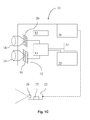
- Fig. 1A shows a schematic view of a system according to a first embodiment of the invention wherein an integrated thermography arrangement 10 comprising three optical systems 14, 18 and 22.
- the optical systems 14, 18, 22 are comprised in an assembly 12.
- the first two optical systems are a visible light imaging system 14 which comprises a visible light sensor array 16 for the visual spectrum of light, and an IR imaging system 18 comprising an IR sensor array 20 for the infrared spectrum of light.
- the third optical system comprised in the assembly 12 is a visible light projecting system 22 or possibly a light projecting system adapted to project light in normally non-visible wavelength areas such as ultraviolet (UV).
- UV ultraviolet
- the three optical systems 14, 18, 22 have a fixed mounting with known relative distances and angles between the respective optical axes OA 1, OA 3, OA 2 as determined through calibration, for instance during production of the thermography arrangement.
- the optical systems of the thermography arrangement 10 are mounted such that the FOV of each optical system at least partly overlaps with the FOVs of the other two optical systems, respectively, as illustrated in the embodiment shown in fig. 2 .
- Fig. 1B shows a schematic view of a system according to a second embodiment of the invention wherein a thermography arrangement 10 comprises the three optical systems 14, 18, 22.
- the two imaging systems 14, 18 have a fixed mounting with known relative distances and angles between the respective optical axes as determined through calibration, for instance during production of the thermography arrangement.
- the visible light imaging system 14 and the IR imaging system 18 are comprised in an assembly 12.
- the projecting system 22 is according to this embodiment a separate component adapted to be detachably attached to the thermography arrangement 10 by means of attachment features 25A and 258. Attachment feature 25A is provided on the projecting system 22 and is adapted to fit to a corresponding attachment feature 25B provided on the thermography arrangement 10.
- the projecting system 22 when attached, is communicatively coupled to the processor 13 of the thermography arrangement 10 via a communication interface 21 further explained below and a corresponding communication interface 27.
- the communication interface 21 may be integrated in, implemented in, or coupled to any of the projecting system 22 or attachment feature 25A, while the communication interface 27 may be integrated in, implemented in, or coupled to any of the imaging systems 14 or 18, assembly 12, processor 13 or attachment feature 25B.
- the visible light projection system 22 when the attachment features 25A, 25B are attached to each other, the visible light projection system 22 will be positioned with a certain distance and angle compared to the IR imaging system 18 and to the visible light imaging system 14, respectively.
- the attachment features 25A, 25B may comprise a socket, a receptacle into which a tapered tool is inserted, and/or be attached to each other by a selection of the following: by means of thread, wherein one of the features 25A, 25B is screwed into the other, by fitting, snapping or clicking one of the features 25A, 25B to the other, by use of magnetism, or by use of any other suitable type of fastening or attachment mechanism.
- the attachment features are placed and designed such that said distances and angles between the visible light projection system 22 on the one hand and the IR imaging system 18 and the visible light imaging system 14 on the other hand will be substantially the same each time the attachment features are attached to each other, with a minor margin of error.
- a parallax between the visible light projection system 22 and the visible light imaging system 14 and IR imaging system 18, respectively may be known from production, calibration during production, or approximated during use.
- the optical systems of the thermography arrangement 10 are positioned such that the FOV of each optical system at least partly overlaps with the FOVs of the other two optical systems, as exemplified in fig. 2 .
- Fig. 1C shows a schematic view of a system according to a third embodiment of the invention wherein a thermography arrangement 10 comprises the three optical systems 14, 18, 22.
- the two imaging systems 14, 18 have a fixed mounting with known relative distances and angles between the respective optical axes known from production or calibration during production.
- the visible light imaging system 14 and the IR imaging system 18 are comprised in an assembly 12.
- the projecting system 22 is according to this embodiment a separate component adapted to be placed physically separated and possibly at a remote distance from the other components of the thermography arrangement 10 during operation.
- the projecting system 22 is communicatively coupled to the processor 13 via a communication interface 21 further explained below.
- the projecting system 22 should be placed such that its FOV at least partly overlaps with the FOV of the IR and visual light imaging systems.
- the projector may be adapted to project a predetermined guide projection of visible light, e.g. in the form of an identifiable feature such as a pattern, to guide a user in placing the projecting system 22 in such a position that it projects its projection FOV onto the scene or object that the user intends to observe.
- the imaging systems 14, 18 comprise, according to embodiments, one or more lenses, control devices for adjusting the lenses, sensors 16, 20 adapted to capture the incoming radiation from an observed scene and coupled to one or more processors 13 provided with processing features adapted for processing image data received from the sensors 16, 20 as well as controlling functions of the different parts of the system.
- the thermography arrangement 10 comprises a display 23 coupled to the processor 13 and being adapted to display image data.
- thermography system 10 including or excluding the visible light projecting system 22, may be handheld, adapted to be fixedly mounted, for instance for surveillance purposes or maintenance investigations, or adapted to be mounted on a stand during use.
- the thermography arrangement 10 further comprises a memory 15 for storing the data registered or processed by the thermography arrangement 10 as well as a selection of one or more control devices 19 for inputting commands and/or control signals, e.g. an interactive display, joystick and/or record/push-buttons and at least one communication interface 21, e.g. wired or wireless connections, IRDA, Bluetooth, USB, Fire-Wire, etc.
- the processor(s) 13 controls functions of the different parts of the thermography arrangement 10.
- the projecting system 22 may comprise a projector 29 e.g. in the form of a laser projector, a liquid crystal display (LCD) projector, a digital light processing (DLP) projector or any other suitable type of projector known in the art.
- a projector 29 e.g. in the form of a laser projector, a liquid crystal display (LCD) projector, a digital light processing (DLP) projector or any other suitable type of projector known in the art.
- a projector 29 e.g. in the form of a laser projector, a liquid crystal display (LCD) projector, a digital light processing (DLP) projector or any other suitable type of projector known in the art.
- LCD liquid crystal display
- DLP digital light processing
- a laser projector may be suitable in many applications since a laser projector typically has a high depth of field, projection of images or data onto any kind of projection surface is enabled. Typically the sharpness, color space, and contrast ratio are higher than those of other projection technologies, for example LCD or DLP projectors.
- thermography arrangement 10 may further comprise a laser pointer, not shown in the figures, per se known in the art.
- laser pointer may applied in the present inventive concept for example be used to project visible light.
- the visible light may be projected as an identifiable feature in the form of a limited pattern comprising all or parts of the pixels comprised in the field of view of the projecting system, herein also denoted FOV proj .
- thermography arrangement 10 comprising an infrared (IR) imaging system 18, a visible light imaging system 14 and a visible light projecting system 22.
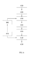
- the method may comprise:
- the infrared (IR) radiation emitted from the observed real world scene is detected using the infrared (IR) imaging system 18, according to the field of view of the infrared (IR) imaging system 18, FOV IR .
- Step 910 Creating a visible representation of the detected infrared (IR) radiation.
- the processor 13 is adapted to transform infrared (IR) radiation data detected by the infrared (IR) imaging system (18) to a visible representation of said detecting infrared (IR) radiation, thereby creating a visible representation of the detected infrared (IR) radiation.
- IR infrared
- Step 920 Aligning the visible representation of the detected infrared (IR) radiation to the detected infrared (IR) radiation emitted from the observed real world scene.
- the processor 13 is adapted to align the visible representation of said detected infrared (IR) radiation to the detected infrared (IR) radiation emitted from the observed real world scene.
- alignment may be achieved using any of the methods described above.
- Step 930 Creating a visible representation of additional information dependent on a signal received from a predetermined source.
- the processor 13 is adapted to create a visible representation of additional information dependent on a signal received from a predetermined source.
- the predetermined source may comprise a selection of the following:
- Step 940 Creating an infrared (IR) image comprising the aligned visible representation of the detected infrared (IR) radiation and the visible representation of additional information.
- the processor 13 is adapted to create an infrared (IR) image comprising the aligned visible representation of the detected infrared (IR) radiation and the visible representation of additional information.
- IR infrared
- Step 950 Presenting the infrared (IR) image by projecting it onto the real world scene, wherein the visible representation of detected infrared (IR) radiation comprised in the infrared (IR) image is projected in alignment with the detected IR radiation emitted from the scene.
- IR infrared
- the visible light projecting system 22 is adapted to present the infrared (IR) image by projecting it onto the real world scene, wherein the visible representation of detected infrared (IR) radiation comprised in the infrared (IR) image is projected in alignment with the detected IR radiation emitted from the scene.
- IR infrared
- an operator aims a handheld thermography arrangement 10 at a scene that may e.g. comprise a pipe, a wall, a floor, a ceiling or any other one or more target surfaces or objects of interest for investigation and directly sees a visible representation of emitted and detected IR radiation projected onto the real world scene, in alignment with the scene in such a way that the visible representation is projected in the same direction as from where the corresponding detected IR radiation was emitted.
- the scene comprises a hot spot, for example an overheated electrical component
- the user will see light projected onto the detected hot spot, for example in a color or light intensity that indicates that the temperature of the detected hot spot is high.
- the light projected onto the hot spot may be red, typically used for representing a hot temperature on a color scale, or light of high intensity, if grey scale values are used for the projection.
- red typically used for representing a hot temperature on a color scale
- light of high intensity if grey scale values are used for the projection.
- any suitable visible representation may be used for the range of thermal, IR or temperature information detected in the scene.
- the user may use the thermography arrangement to light up or highlight areas of interest in an observed scene or receive a warning in the form of a visible or audible alarm being projected onto the scene when an abnormality is detected.
- the user may use the thermography arrangement to find the distance to an observed scene.
- the distance from the thermography arrangement to the observed scene will hereinafter be referred to as z, wherein z is a parameter that indicates the distance from the thermography arrangement to the observed scene.
- the distance z may be for instance be retrieved by calculation using relationships with known parameter and/or parameters that the thermography arrangement is enabled to retrieve, for instance the relationship of Eq. 2 presented below.
- the distance z may be retrieved by use of double visible light sensors, detection of a laser spot in an IR image, the position of the focus lens or by use of a distance sensor integrated in or coupled to the thermography arrangement in per se known manners.
- thermography arrangement In order for the thermography arrangement to work as a distance meter, it must first be calibrated. Alternative calibration embodiments are described below.
- the operator may select to activate an alignment function using input features comprised in the one or more control devices 19.
- the alignment function is automatically activated when the thermography arrangement 10 is turned on.
- the visible light projecting system 22 is a detachably attachable component, as exemplified in Fig. 1B , and presently not attached to the handheld thermography arrangement 10, the operator attaches the visible light projecting system 22 to the handheld thermography arrangement 10 before use.
- the operator places the visible light projecting system 22 in a suitable position relative to the handheld thermography arrangement 10, making sure that the projecting system 22 is directed towards target surfaces or objects of interest for investigation. Possibly, the operator is guided in directing the visible light projector towards the target surfaces or objects of interest for investigation by the visible light projecting system 22 being adapted to project a predetermined guide projection of visible light, e.g. an identifiable feature in the form of a pattern or a symbol.
- a predetermined guide projection of visible light e.g. an identifiable feature in the form of a pattern or a symbol.
- the visible light may be projected as an identifiable feature in the form of a limited pattern comprising all or parts of the pixels comprised in the field of view of the projecting system (FOV proj ) .
- a projection may for instance be automatically activated when the visible light projecting system 22 is turned on, or be controlled to be activated by input from the operator.
- the operator may provide input using for example an input device integrated in or coupled to the visible light projecting system 22, not shown in the figure, or the control devices 19 of the thermography arrangement 10, whereby the processor 13 translates the input signal from the control device(s) 19 to a control signal that is communicated to the visible light projecting system 22 via the interface 21, in order to control the activation of the described guiding projection.
- the visible light projecting system 22 is communicatively coupled to the processor of the thermography arrangement by means of a wired or wireless connection, for instance communicating via communication interfaces 21 and 27.
- the IR imaging system 18 of the IR imaging system 10 detects IR radiation emitted from the observed scene and captures said IR radiation using an IR sensor array 20 comprised in the IR imaging system 18.
- the incoming IR radiation is turned into an IR radiation signal comprising IR radiation data.
- the captured IR radiation data is transmitted from the IR sensor array 20 to the processor 13, wherein the IR radiation data is transformed to image data in the form of an IR image.
- the IR image is transferred to a display 23 of the thermography system 10 and presented to the operator of the device.
- the display of the IR image on a camera display is optional according to method embodiments of the present invention.
- the visible light projecting system 22 is controlled by the processor 13 to project visible light onto the observed scene.
- the visible light may be projected as an identifiable feature in the form of a limited pattern or symbol comprising all or parts of the pixels comprised in the field of view of the visible light projecting system 22, ( FOV proj ).
- FOV proj the visible light projecting system 22
- the projection is performed in parallel with but not necessarily at the same time instance as the capturing and processing of IR radiation information.
- a pattern or symbol in the context of the present invention is a shape or distribution consisting of at least one pixel and preferably more than one pixel, typically a number of pixels, which are easily distinguishable from anything that may appear in an image of an observed scene.
- the symbol is in preferred embodiments not in the form of a single pixel or a few pixels grouped together, since a single pixel or small pixel group may be confused with noise appearing in the image.
- the symbol of the present invention may have the shape of an object recognizable by the human eye, such as a flower, a star or any other object known to a human.
- a pattern in the context of the present invention also consists of more than one pixel, typically a number of pixels, which are easily distinguishable from anything that may appear in an image of an observed scene, as well as from noise.
- the symbol or pattern may have the shape of an object known to man or any other suitable shape or distribution that renders it easily recognizable by the human eye and/or a data processor.
- the pattern projected by the visible light projecting device 22 is simply all or selected parts of the pixels comprised in the FOV proj . In this case, the pattern may be identified or recognized, in a visible light image comprising the pattern, based on the intensity of the projected visible light. The pixels wherein visible light is projected are likely to have a higher intensity remaining pixels of the visible light image.
- the visible light imaging system 14 is controlled by the processor 13 to capture incoming visible light using a visible light sensor array 16 comprised in the visible light imaging system 14.
- the incoming visible light is turned into a visible light signal comprising visible light data.
- the captured visible light data is transmitted from the visible light sensor array 16 to the processor 13, wherein the visible light data is transformed to a visible light image.
- the sensor elements of the visible light sensor array 16 are sensitive to the wavelength of the visible light, the reflected light of the visible light projecting system 22 may be detected in the visual image by its picture elements, i.e. pixels.
- the picture elements may for example be CCDs (charge-coupled devices).
- the captured visible light image thereby comprises a visible representation of the real world scene superimposed by the predetermined symbol or pattern that is being projected onto it.
- the image is transmitted to the processor 13, which performs detection of the predetermined symbol or pattern in the image.
- Detection of the symbol or pattern in the image may be performed using any suitable detection method, per se known in the art, for example feature extraction, template matching, segmentation, edge detection, thinning, similarity measures, masking, filtering or by using a difference image.
- the visible light imaging system 14 is further controlled by the processor 13 to capture an image of the same real world scene without the predetermined symbol or pattern projected onto it, at a time instance close to the time instance when the image comprising the scene and the predetermined symbol or pattern is captured. It does not matter which of the images is captured first and which is captured last.
- the two images are two successive image frames in an image frame sequence. The reason for capturing the images in close succession to each other is that the real world scene normally will not have changed much from the first image frame to the second, meaning that the real world image part of the images will be substantially the same.
- thermography arrangement 10 any shaking or moving of the arrangement caused by the user will be small if the images are captured in close succession, for example as two consecutive image frames in an image frame sequence.
- the processor 13 subtracts the image comprising only the representation of the real world scene from the image further comprising the projected symbol or pattern, a difference image comprising only the projected symbol or pattern will be obtained.
- any symbols or patterns present in the observed scene for example patterns on a wallpaper of a wall, may not wrongfully be detected as a symbol or pattern by the thermography arrangement 10.
- the visible representation of IR information is transmitted from the processor 13 to the visible light projecting system 22.
- the visible light projecting system 22 is further controlled by the processor 13 to project the visible representation of IR information onto the real world scene such that the visible light representation of the detected IR radiation is aligned with the incoming, or captured, IR radiation and projected onto the real world scene in the same direction as from where the corresponding captured IR radiation was emitted.
- the processor 13 uses the information on the detected symbol or pattern along with information retrieved during production, calibration in production, and/or calibration or adjustment during operation of the thermography arrangement 10. Alignment embodiments are described in further detail below.
- the operator of the thermography arrangement 10 will experience that the events described above are performed instantly, in real time, meaning that the operator aims the thermography arrangement 10 at a real world scene comprising e.g. a surface or an object of interest and directly sees a visible representation of emitted and detected IR radiation projected onto the real world scene, in alignment with the scene in such a way that the visible representation is projected in the same direction as from where the corresponding detected IR radiation was emitted.
- the visible representation of IR information is typically colors or gray scale levels representing different thermal properties of the surfaces or objects onto which it is projected. Using the alignment method of the present invention, the visible representations projected onto the real world scene will be projected in the direction from which the corresponding detected IR radiation was emitted.
- the visible light projecting system 22 will project onto this part of the scene light having a color or a gray scale value representing said low thermal or temperature value, according to e.g. the color scale or range of gray scale values selected.
- the detection of an area with low thermal values or temperatures is sometimes referred to as detection of a "cold spot", which may indicate that the area for instance is poorly insulated, or is exposed to water leakage or formation of condensation and thereby has an increased risk of being water damaged.
- detection of an area with high thermal values or temperatures is sometimes referred to as detection of a "hot spot”, which may indicate for instance that the area comprises overheated components and has an increased risk of catching fire. If a color scale ranging from blue for low temperatures to red for high temperatures is used, a cold spot in the real world scene would typically have blue colored light projected onto it, while a hot spot in the real world scene would have red colored light projected onto it by the visible light projecting system 22.
- the operator is thereby enabled to see the hot and cold spots directly in the real world scene that he or she is investigating, in alignment with the scene, even if the cause of the low or high thermal or temperature values is on the other side of a surface at which the operator is aiming the IR imaging system 10.
- red and blue areas described above are by means of example only. Any color scale, gray scale, or other suitable visible representation may be used by the visible light projecting system 22 to represent the different IR radiation levels detected. For instance, different IR radiation levels may be represented by different patterns or light intensities.
- the visible light projecting system 22 may project visible light according to the selected visible representation of detected IR radiation levels onto the parts of the real world scene that are within its entire FOV if the FOV of the visible light projecting system 22 is completely comprised in the FOV or the IR imaging system 18. Alternatively, if the FOV of the visible light projecting system 22 only partly overlaps with the FOV or the IR imaging system 18, the visible light projector may project visible light onto the parts of the scene that lie within the overlapping part of the FOVs of the two systems. Alternatively, the visible light projecting system 22 projects visible light only onto parts of the real world scene from which IR radiation above, below or between certain selected temperature values or intervals has been detected and that lies within the overlapping part of the FOVs of the two systems.
- visible light may be projected onto areas of interest indicated by the operator, using input features of the IR imaging system 10, or onto objects detected in the image by object detection features implemented in the processor 13.
- the visible light imaging system 14 has the largest FOV
- the IR imaging system 18 has the second largest FOV
- the projecting system 22 has the smallest FOV.
- any other relationship in FOV sizes is conceivable, depending on circumstances such as price, performance and end customer requirements.
- the projected visible light is aligned with the detected IR radiation emitted from the real world scene and projected in the direction from which the detected IR radiation was emitted, no visible light will be projected onto parts of the real world scene that does not fall within the FOVs of both the IR imaging system 18 and the visible light projecting system 22.
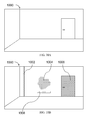
- FIG. 10A and 10B Examples of projection embodiments are shown in Figs. 10A and 10B .
- Fig. 10a shows a real world scene 1000 that comprises a room with a floor, walls and a door.
- Fig. 10b shows the same real world scene 1000, wherein a representation of IR information emitted from objects in the scene is presented onto the scene as visible light, for example in the form of different colors or light intensities representing different measured levels of IR radiation.
- a representation of IR information emitted from objects in the scene is presented onto the scene as visible light, for example in the form of different colors or light intensities representing different measured levels of IR radiation.
- an intensity scale or a color scale wherein different temperature intervals are represented by different intensity levels or colors may be used, as is well known in the art.
- the visible light is presented onto the scene 1000 by means of a visible light emitting device, such as for instance a liquid crystal display (LCD), a digital light processing (DLP) projector or a laser projector.
- a visible light projection is illustrated as different half-tone levels representing different detected temperature values or temperature intervals in the scene.
- the projector only projects visible light onto parts of the scene, for instance according to user selections of areas of interest, or preset or user selected IR radiation values or intervals of interest.
- a pipe 1002, an area 1004 on the back wall and the door 1006 are the targets of projected visible light.
- the different halftone patterns of the target areas 1002, 1004, 1006 may instead be different colors or light intensities, representing different IR radiation levels or intervals.
- the halftone pattern (color, light intensity) of the pipe 1002 may indicate an IR radiation level or interval corresponding to a high temperature value or interval, indicating to the user that this area is a "hot spot".
- the halftone pattern (color, light intensity) of the area 1004 may in turn correspond to a low temperature, indicating to the user that this is a "cold spot", and the halftone pattern (color, light intensity) of the door 1006 may relate to a third temperature value or interval, possibly between the temperature values or intervals of 1002 and 1004.
- additional information 1008 may further be projected.
- additional information 1008 is exemplified as length unit or length measurement information, in the form of a ruler, projected to scale onto the observed scene, thereby aiding a user in interpreting the size or distribution of for example objects in the observed scene and/or areas of projected visible light. Additional information according to different embodiments is presented below.
- the additional information comprises a guiding help grid, or grid lines.
- the guiding help grid or grid lines provides length/area measurement information projected onto the scene to scale, thereby aiding the user in interpreting the sizes/areas/distances of different parts of or objects present in the scene.
- the grid or grid lines provide relative length/area information, helping a user relate sizes/areas/distances of different parts of or objects present in the scene to each other.
- the additional information comprises orientation information, for example obtained from a gyroscope integrated in or coupled to the thermography arrangement 10.
- the orientation information is used to project a level, or bubble level, onto said scene, thereby aiding the user in interpreting the orientation of parts of the observed scene.
- the additional information may comprise temperature related information, such as temperature values or levels or humidity values or levels obtained from the captured IR radiation information, in manner known in the art.
- the temperature related information may be comprised in the IR image projected onto the observed scene as numeric values or intervals or as any other suitable visible representation that will aid a user in interpreting or analyzing the observed scene.
- the additional information comprises writing/text, a sketch and/or a drawing, for example input by a user using one or more of the control devices 19.
- the additional information is input through touch functionality.
- thermography arrangement 10 According to embodiments wherein at least one distance z from the thermography arrangement 10 to the observed scene is known or retrieved, length and/or area of a part of the scene may be calculated, in manners known in the art.
- creating an infrared (IR) image in Step 940 above further comprises ensuring that the visible representation of additional information will be projected onto said scene to scale, dependent on the retrieved distance z or the calculated at least one distance and/or area.
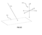
- the projection surface is a substantially flat wall, which is the easiest possible case for projection.
- the objects and parts of the scene onto which visible light is projected are typically at different distances from the IR imaging system 10, as shown in the embodiment of fig. 3 , meaning that the projected light must be aligned with the observed scene, for instance according to the method embodiments presented herein in connection with Fig. 2-8 .
- Relevant information may for example be hot or cold spots or areas in an investigated scene, indicating energy thieves, or power thieves, caused by for example poor insulation, or malfunctioning or overheated electrical components.
- different aspects of the invention may be used to enhance or highlight for example detected moisture over/under/in between certain predefined levels, wherein the moisture level may be calculated from measured IR or temperature information in manners known per se.
- different aspects of the invention may be used to inform the user of the location of heating in floor, electrical wiring, water pipes or the like, which may for example be advantageous for a user in the construction or electrical business.
- relevant information is projected onto a scene
- a user may, aided by the projection, draw, mark, write or sketch onto the scene information that relates to the projected information or conclusions drawn by the user, thereby enabling easier analysis even after the projection is turned off.
- additional information may comprise graphical elements presented in a graphical user interface (GUI) on a display of the thermography arrangement, wherein said graphical elements represent a selection of the following:
- the user is enabled to control what is being presented, or the appearance of what is being presented, in the GUI on the display of said thermography arrangement.
- the user may be enabled to control the GUI by interaction with the thermography arrangement 10, using one or more of the control devices 19.
- the user interacting with one or more of the control devices 19 generates input and/or control signals adapted to be interpreted by the processor 13, or another processing device integrated in or coupled to the thermography arrangement.
- the processing unit is adapted to change the appearance of the GUI shown on the display of the thermography arrangement 10 and/or what is being projected as additional information onto the observed scene. Whether parts or all of the information comprised in the GUI shown on the display of the thermography arrangement is also going to be projected onto the observed scene may either be preset or selected by the user, for example through interaction with one or more of the control devices 19.
- a user is enabled to select between different projection modes, for example using one or more of the control devices 19.
- possible projection modes comprise a selection of the following:
- the brightness levels and/or color values of the visible light projected may be adjusted, based on the brightness levels and/or color values of the parts of the observed scene onto which the visible light is projected.
- the brightness levels and/or color values of the projected visible light are typically adjusted such that the projected visible light can be distinguished as clearly as possible by the human eye from the parts of the scene onto which it is projected. For example, if the scene is black, visible light of high brightness may be projected, if the relevant part of the scene is green, a different color, typically a contrasting color may be projected, so that the projection is clearly visible in the scene.
- adjustments of the projected visible light may be done by controlling the visible light projecting system 22 to project light of certain brightness levels and/or colors during operation, or by adjusting the brightness levels and/or colors of the IR image before sending it to the projector.
- brightness levels and/or colors may be preset, calculated based on the colors of the scene onto which the visible light is to be projected or selectable by a user, for example using one or more of the control devices 19.
- the processor 13 may be adapted to detect the brightness levels and/or color values in a visible light image (captured by the visible light imaging system) of the observed scene; calculate brightness levels and/or color levels based on the detected brightness levels and/or color levels.
- the processor 13 may be adapted to adjust the brightness levels and/or color levels of the IR image before it is transferred to the visible light projecting system 22, or to control the visible light projecting system 22 to adjust the brightness levels and/or color levels of the projected visible light, based on the preset, calculated or user selected brightness levels and/or color levels.
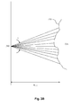
- Fig. 2 illustrates the field of view (FOV) of the visible light imaging system 14, of the thermography arrangement 10 of fig. 1 , represented as an angle ⁇ , the FOV of the infrared imaging system 18 represented as an angle ⁇ , and the FOV of the visible light projecting system 22 represented as an angle ⁇ .
- the optical axes of the three optical systems 14, 18 and 22 are shown as dashed lines OA 1, OA 3 and OA 2, respectively.
- the respective distances between the imaging systems 14, 18, 22 causes a displacement of the images that is constant in meters but decreases in number of pixels with increasing distance to the object.
- the optical axes OA 1, OA 3, OA 2 of the different imaging systems 14, 18, 22 are normally not perfectly parallel.
- the respective angle between them causes a displacement, also referred to as a pointing error or directional error, which varies in meters with the distance to the object but is constant in number of pixels.
- a pointing error, or directional error is caused by the difference in angle between the optical axes of two of the optical system compared to the desired angle, and occurs due to construction inaccuracies. For instance, when the visible light imaging system 14 and the IR imaging system 18 are assembled in production, they will not be assembled in exactly the same way for every thermography arrangement 10. Slight differences will occur, and thereby also directional errors.
- parallax as used in the present text includes the combined pixel displacement caused by the distance between the imaging subsystems and the angle between the optical axes.
- the parallax distance P ( p-vis ) causes a pixel displacement between a visual image projected by the visible light projecting system 22 and an image captured by the visible light imaging system 14. This pixel displacement is hereinafter denoted d ( pix vis ).
- the parallax distance P causes a pixel displacement between a visual image projected by the visible light projecting system 22 and an IR image captured by the IR imaging system 18. This pixel displacement is hereinafter denoted d ( pix IR ) .
- the visible light imaging system 14 and the IR imaging system 18 are integrated in the assembly 12, whereby the parallax distance P ( vis-IR ) is known from production and may be compensated for during calibration or operation of the thermography arrangement 10.
- the pixel displacements d ( pix vis ) and d ( pix IR ), shown in fig. 2 maybe determined empirically as a function of the distance z ( x,y ) that represents the distance from the thermography arrangement 10 to each of a selection of points on the observed real world object, objects or scene, for example during production or calibration of the thermography arrangement 10.
- the distance z may be described as the distance to the part of the scene representing a specific coordinate in the captured visual image in which the projected pattern is detected, in combination with the parallax distance P ( p-vis ) between the visible light projecting system 22 and the visible light imaging system 14.
- the determination of the pixel displacements as a function of the distance z from the thermography arrangement to the observed scene may hence be performed for the visible light imaging system 14 and the IR imaging system 18, respectively, using methods known per se.
- the determined pixel displacements as a function of the distance z are stored in a memory in the thermography arrangement 10, for example, the memory storage 15, and can be used to compensate for parallax errors during operation.
- the distance z is determined relative to a predetermined coordinate in the image, such as the center of the image, a corner of the image or any other suitable coordinate in the image.
- the respective parallax distances P ( p-vis ) , P ( p-IR ) and pointing errors, or directional errors, between the optical systems of the thermography arrangement 10 may be used to estimate equations or curves for the displacement as a function of the distance to the object.
- This equation or curve may be stored in a memory in the thermography arrangement 10, for example the memory storage 15, and can be used to compensate for parallax errors during operation through mapping of a determined distance to the relevant parallax distance equation or curve.
- the projected predetermined symbol or pattern consists of more than one pixel, typically a number of pixels.
- the symbol or pattern is more reliably determined than if only one pixel/one point was used for determining the distance.
- the symbol or pattern since the symbol or pattern has a shape or distribution that is easily distinguishable from anything that may appear in an image of an observed scene and may have the shape of an object known to man or any other suitable shape or distribution that renders it easily recognizable by a data processor, whereas a single pixel may be confused with other objects or noise present in the image.
- the parallax distance P ( p-vis ) causes the pixel displacement d ( pix vis ) between a visual image projected by the visible light projecting system 22 and an image captured by the visible light imaging system 14 and the parallax distance P ( p-IR ) causes the pixel displacement d ( pix IR ) between a visual image projected by the visible light projecting system 22 and an IR image captured by the IR imaging system 18.
- the parallax distance P ( p-vis ) causes the pixel displacement d ( pix vis ) between a visual image projected by the visible light projecting system 22 and an image captured by the visible light imaging system 14
- the parallax distance P ( p-IR ) causes the pixel displacement d ( pix IR ) between a visual image projected by the visible light projecting system 22 and an IR image captured by the IR imaging system 18.
- the processor 13 is arranged to perform alignment of images captured by and/or light projected by any or all of the optical systems 14, 18, 22.
- the displacement between the projected visible light and the detected IR radiation must be calculated, or approximated, and compensated for. According to different embodiments presented below, calculation or approximation of this displacement is performed either in calibration during production, self-calibration or self-adjustment during operation of a thermography arrangement 10.
- the visible light imaging system 14, the IR imaging system 18 and the visible light projecting system 22 are all assembled in an integrated thermography arrangement 10, for example integrated in an assembly 12 ⁇ , with known distances between the different optical devices 14, 18, 22, and optical axes OA 1, OA 3, OA 2, respectively.
- the thermography arrangement may be calibrated in production.
- all parallax distances are known since the distances between the optical axes OA 1, OA 3, OA 2 are known.
- Other parameters that are known when calibration is performed during production are: the field of view of the visible light imaging system 14 (FOV vis ); the field of view of the IR imaging system 18 (FOV IR ); distance z to the observed scene; and the translation, or mapping function, f (z)between image coordinates of an image captured using the visible light imaging system 14 and an image captured using the IR imaging system 18, as a function of z.
- the distance z is determined relative to a predetermined coordinate in the image, such as the center of the image, a corner of the image or any other suitable coordinate in the image.
- Embodiments of production calibration methods comprise the following steps, illustrated in Fig. 4A :
- the visible light projected may be in the form of an identifiable feature such as a pattern or symbol.
- Step 420 Capture a visible light image, comprising the projected visible light, using the visible light imaging system 14.
- two visible light images are captured, wherein one comprises the scene and the projected visible light while the other comprises the scene without the projected visible light.
- the projecting device projects visible light onto the scene during the time when one of the images is captured, but not while the other image is captured.
- a difference image comprising the projected visible light, but not the observed scene, is obtained.
- Step 430 Detect the projected visible light in the visible light image, or in the difference image if such an image has been obtained in Step 420.
- the distance z may in an optional Step 485 be used as input to the detection of the projected visible light.
- a more efficient detection is obtained as the detection starts in the most probable location, or coordinates, of the visible light image.
- Step 440 Calculate the pixel displacement d (pix vis) between the light projected by visible light projecting system 22 and the image captured by the visible light imaging system 14, based on the captured visible light image. In other words, determine the displacement in pixels, d ( pix vis ) , between the projected pixel coordinates and pixel coordinates in the visible light image where the projected visible light would appear if the visible light imaging system 14 and the visible light projecting system 22 were aligned, for instance known from production or calibration.
- An example of a pixel displacement d ( pix vis ) is shown in fig. 2 .
- the pixel displacement may for example be expressed as divided into an x direction component and a y direction component ( dx ( pix vis ) , dy ( pix vis ) ) or expressed as polar coordinates, depending on circumstances.
- Step 450 Calculate the FOV of the projector, FOV proj , if it not already known.
- FOV proj may be calculated based on the captured visible light image, or difference image, comprising the projected visible light, that may be represented as an area, an identifiable feature, a pattern or a symbol, in the following way:
- the captured visible light image comprising the projected visible light area, feature, pattern or symbol
- the pixel distance between predetermined points of the projected visible light area, feature, pattern or symbol is determined. Since the resolution, in pixels, of the visible light image is known, the percentage of the visible light image, and thereby the percentage of FOV vis that is represented by the distance between the two point of the projected visible light area, feature, pattern or symbol may be determined based on said pixel distance. Knowing FOV vis and further knowing the relationship between the percentage of the FOV vis and the FOV proj , respectively, that represents the distance between the predetermined points of the projected visible light area, feature, pattern or symbol, FOV proj may be determined.
- Step 460 Determine calibration parameters in the form of the calibration parameters c 0 and c 0 .
- the calibration parameter c 0 is a theoretical constant relating to the parallax distance between the optical axes of the two optical systems compared, for example the optical axes OA1, OA2. According to an embodiment, c 0 is expressed in (length unit x number of pixels).
- the calibration parameter c 1 relates to the pointing, or directional, error.
- c 1 relates to the angle between the optical axes of the two optical systems compared, for example the optical axes OA1, OA2.
- c1 is expressed in pixels.
- the calibration parameters may for example be expressed as divided into an x direction component and a y direction component (c 0x , c 0y ), (c 0x , c 0y ) or expressed as polar coordinates, depending on circumstances.
- Step 490 Calibrate the optical systems of the thermography arrangements, or in other words compensate for parallax error, or pixel displacement and pointing error, determined in step 460.
- thermography arrangement After the calibration in Step 490, a projection produced by the projecting system 22 will be aligned with the IR radiation captured by the IR imaging system 18.
- the thermography arrangement is ready to operate, and may further, according to embodiments, be used as a distance sensor during operation.
- the calibration process described above is performed more than once, for example two or three times, in order to ensure proper calibration.
- FIG. 8 Embodiments of the operation of a calibrated or aligned thermography arrangement are illustrated in Fig. 8 .
- thermography arrangement is adapted for self-calibration and the parallax distances between the visible light projecting system 22 on the one hand and visible light imaging system 14 and IR imaging system 18, respectively, on the other hand may be approximated.
- an attachment feature 25A is provided on the projecting system 22 and is adapted to fit to a corresponding attachment feature 25B provided on the IR imaging system 10 so that the projecting system 22 can be attached to and detached from the IR imaging system 10.
- the visible light projecting system 22 is according to an embodiment positioned with a certain distance and angle compared to the IR imaging system 18 and the visible light imaging system 14 respectively, substantially the same each time the attachment features are attached to each other, with a minor margin of error.
- the thermography arrangement is self-calibrating.
- the following parameters are known from production: the parallax distance and pointing error between the visible light imaging system 14 and the IR imaging system 18; the field of view of the visible light imaging system 14 (FOV vis ); the field of view of the IR imaging system 18 (FOV IR ); and the translation, or mapping function, f ( z )between image coordinates of an image captured using the visible light imaging system 14 and an image captured using the IR imaging system 18, as a function of the distance z to the observed
- the aim of the self-calibration is to estimate the pointing error and, if it is not already known, the field of view of the projecting system 22 (FOV proj )
- Embodiments of methods for self-calibration comprise the following steps, illustrated in Fig. 4B :
- the calibration process described above is performed more than once, for example two or three times, in order to ensure proper calibration.
- FIG. 8 Embodiments of the operation of a calibrated or aligned thermography arrangement are illustrated in Fig. 8 .
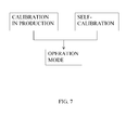
- thermography arrangement Once a thermography arrangement has been calibrated according to any of the embodiments presented above, relating to Figs. 4A and 4B , the arrangement is ready for operation. In operation, the thermography arrangement will work in the same way, regardless of whether the calibration has been performed in production or during use, as illustrated in Fig. 7 .
- thermography arrangement that has been calibrated in production, as well as a self-calibrating thermography arrangement, is calibrated or aligned after Step 490 according to embodiments of the method embodiments presented above.
- a projection produced by the projecting system 22 will be aligned with the IR radiation captured by the IR imaging system 18.
- the thermography arrangement is ready to operate, and may further, according to embodiments, be used as a distance sensor during operation.
- Eq. 2 may for example be expressed as divided into an x direction component and a y direction component, or expressed as polar coordinates, depending on circumstances.
- Eq. 2 may alternatively be used to determine any of the parameters c 0 , c 1 , z or d ( pix vis ) if the remaining parameters of the equation are known.
- a calibrated thermography arrangement produces a visible light projection onto an observed scene, in alignment with IR radiation emitted from the observed scene and received by an IR sensor of an IR imaging system of the thermography arrangement, by obtaining or retrieving the distance z to the observed object, objects or scene; determine the pixel displacement d pix vis based on the distance z and calibration parameters C 0 and C 1 determined in production or during self-calibration, as described above, and method embodiments comprising the following steps:
- the distance z may be for instance be retrieved by calculation using relationships with known parameter and/or parameters that the thermography arrangement is enabled to retrieve, for instance the relationship of Eq. 2 presented above.
- the distance z may be retrieved by use of double visible light sensors, detection of a laser spot in an IR image, the position of the focus lens or by use of a distance sensor integrated in or coupled to the thermography arrangement in per se known manners.
- the retrieved distance z is used as input to Step 830.
- Step 830 Calculate the pixel displacement d pix IR between a visual image projected by the visible light projecting system 22 and an IR image captured by the IR imaging system 18.
- the relationship between the pixel displacement d pix IR and the pixel displacement d pix vis , between a visual image projected by the visible light projecting system 22 and a visible light image captured by the visible light imaging system 14, as a function of the distance to the observed object, objects or scene, is known from production or calibration.
- the relationship is a mapping function, for instance expressed as a lookup table, wherein every value for d pix vis has a corresponding value for d pix IR , based on the value of the distance z.
- each displacements is here formulated as one value d pix vis or d pix IR .
- the displacements may comprise more than one component.
- a displacement is described in terms of an x component and a y component, for instance in the form of a vector (e.g. dx pix vis, dy pix vis ), or as polar coordinates.
- the distance z is known from Step 820. Therefore, in order to determine d pix IR we first need to know d pix vis . If the displacement d pix vis is not already known, it may as described above be determined using the known parameters C 0 and C 1 and the relationship presented in Eq. 2.
- the pixel displacement d pix IR is determined by using the relationship of Eq. 3 according to any of the embodiments presented above.
- Step 840 Present the IR image onto the observed scene in alignment with the observed scene. In other words, presenting the IR image onto the observed scene in alignment with IR radiation emitted from the observed scene.
- the IR image is aligned to the observed scene, or in other words aligned to the IR radiation emitted from the observed scene, by compensating for the pixel displacement d pix IR determined in Step 80.
- the alignment, or compensation may be performed in the processor 13 of the thermography arrangement 10, or in another processor integrated in or coupled to any of the components of the thermography arrangement 10.
- presenting the aligned IR image onto the observed scene comprises transferring an aligned IR image to the visible light projecting system 22 and projecting the aligned IR image onto the observed scene using the visible light projecting system 22.
- presenting the aligned IR image onto the observed scene comprises transferring an IR image to the visible light projecting system 22, aligning the IR image using a processor integrated in or coupled to the visible light projecting system 22, and projecting the aligned IR image onto the observed scene using the visible light projecting system 22.
- FOV proj is smaller than FOV IR .
- the visible light projecting system 22 will not be adapted to display the entire IR image. Therefore, a part of the IR image that corresponds to the FOV proj is obtained, for example by selecting, cropping or cutting out said part from the IR image, and then projected onto the scene.
- thermography arrangement is self-adjusting or self-aligning, or in other words adjusts or aligns itself during operation.
- the thermography arrangement produces a visible light projection onto an observed scene, in alignment with IR radiation emitted from the observed scene, by: receiving IR radiation emitted from an observed scene using an IR sensor of an IR imaging system of the thermography arrangement; converting the received IR radiation into a visible representation in the form of an IR image; obtaining or retrieving the distance z from the thermography arrangement to the observed object, objects or scene; determining the pixel displacement d pix vis ; converting pixel displacement d pix vis to pixel displacement d pix IR ; aligning the IR image by compensating for the pixel displacement d pix IR ; and projecting the aligned IR image onto the observed scene, thereby obtaining presentation of an IR image onto a scene, in alignment with the IR radiation emitted from the scene.
- the parallax distances between the visible light projecting system 22 on the one hand and visible light imaging system 14 and IR imaging system 18, respectively, on the other hand are not known, since the visible light projecting system 22 is a component that is physically separated from the other optical systems 14, 18, at an unknown and non-constant distance from the optical systems 14, 18.
- This embodiment is shown in fig. 1C and further described above, in the section Separate components embodiment.
- the parallax distance and pointing error between the visible light imaging system 14 and the IR imaging system 18 are known from production: the parallax distance and pointing error between the visible light imaging system 14 and the IR imaging system 18; the field of view of the visible light imaging system 14 CFOV vis ); the field of view of the IR imaging system 18 (FOV IR ); and the translation, or mapping function, f ( z )between image coordinates of an image captured using the visible light imaging system 14 and an image captured using the IR imaging system 18, as a function of the distance z to the observed scene.
- the aim of the self-alignment is to estimate the pointing error and the field of view of the projecting system 22 (FOV proj ), in order to enable alignment of the different optical systems of the thermography arrangement.
- Steps 410, 420, 440, 450, 470 and 480 correspond to the same steps presented above, relating to Fig. 4B .
- Embodiments of self-adjustment further comprise the following steps, illustrated in Fig. 6 :
- Step 620 comprises transferring the IR image in the form of an IR image signal, from the processor 13 to the visible light projecting system 22, whereby the projector 29 of the visible light projecting system 22 projects the resampled IR image data onto the real world scene.
- the IR image data is thereby projected in alignment with the real world scene, in other words the IR image data is projected in the direction from which the corresponding detected IR radiation information was emitted.
- the self-alignment described above does not result in calibration of the thermography arrangement. Instead, the self-alignment, or self-adjustment, is performed continuously during operation, through the conversion or mapping of Step 610.
- the calibration process described above is performed more than once, for example two or three times, in order to ensure proper adjustment.
- the real world scene is illustrated as a flat surface 200.
- the object, objects or scene that a user of the IR imaging system 10 is analyzing will rarely consist of a flat surface that is perfectly orthogonal to the optical axis of the visual light projector 22.
- FIG. 3A an optical system of the IR imaging system used on a surface that is not orthogonal to the optical axis of the visual light projector 22 is shown.
- the surface in fig. 3A is inclined in one dimension in relation to the optical axis of the visual light projecting system 22.
- the surface may just as well be inclined in two dimensions relation to the optical axis of the visual light projecting system 22.
- this would relate for example to an operator using the device 10 to project a visible representation of detected IR radiation information onto a heated floor that is being investigated. Since the operator is standing on the floor, this makes it difficult for him or her to hold the device 10 such that the optical axis of the projecting system 22 is orthogonal to the floor.
- This exemplary embodiment is further illustrated in fig. 3C , where the optical axis OA of the projecting system 22 (not shown in the figure) falls obliquely onto an investigated surface, in this case a floor 310, in such a direction that it is inclined in two dimensions, by way of example the x- and z-directions of the coordinate system 330.
- non-flat surface 310 is shown in fig. 3B , for which different embodiments of the present invention can also advantageously be used, according to the method described further below, especially for embodiments of the invention where several distances to the observed scene are retrieved as described below.
- the non-flat surface 310 of fig. 3B is one example of what such a surface might look like. Since the surface is a the surface of a real world object, any 3D shape is possible, comprising any combination of flat surface parts, curved parts and/or embossed parts.
- an optical system 300 with an optical axis OA and a FOV with the angler is shown. Only one optical system is shown in figs. 3A and 3B , instead of all three optical systems as shown in fig. 2 . This is merely for the sake of simplicity of the drawing.
- the optical system 300 may alternately represent the visible light imaging optical system 14, the IR imaging system 18 or the visible light projector 22.
- Step 512 in connection with Fig. 5 , more than one distance to more than one point in the observed scene may be calculated and turned into a distance map.
- a distance map enables projection of the visual representation of the IR image onto the observed real world scene to be aligned with the object or objects comprised in the scene at different depths, since each projected pixel may be adapted to be projected at the right distance, dependent on the distance map.
- the thermography arrangement 10 may be adapted to project pixels with varying density, dependent on the distances of the distance map, or distance image and preset conditions.
- the thermography arrangement maybe adapted to project pixels more sparsely if the distances z i to the points i on the object, objects or scene onto which the pixels are to be projected exceeds a preset threshold. In this way, a more detailed projection is provided for projected parts of the scene that are close to the thermography arrangement 10.
- the thermography arrangement 10 may instead be adapted to project pixels more closely if the distances z i exceed a preset threshold, thereby providing a more detailed projection for projected parts of the scene that are far from the thermography arrangement 10.
- the thermography arrangement 10 may be adapted to project pixels more sparsely or closely when the distances z i are within certain intervals. There may be one or more intervals and/or thresholds. The intervals and/or thresholds may be predefined and stored in the memory 15 thermography arrangement 10 or selected and input by an operator of the thermography arrangement 10, using input features comprised in the one or more control devices 19 communicatively coupled with the interface medium 21 of the IR imaging system 10.
- image processing features of the processor 13 may according to embodiments resample the IR image data, dependent on the predefined or operator input interval, intervals, threshold, threshold or other values describing the distribution of the pixels to be projected.
- the resampled IR image is transferred, in the form of an IR image signal, from the processor to the visible light projecting system 22.
- the projector 29 of the visible light projecting system 22 projects the resampled IR image data onto the real world scene.
- the IR image data is thereby projected in alignment with the real world scene, in other words the IR image data is projected in the direction from which the corresponding detected IR radiation information was emitted.
- the projector 29 is enabled to project larger pixels onto points in the real world scene that are found to be at a greater distance from the IR imaging system 10, i.e. a greater distance from the operator, and smaller or regular sized pixels when the detected distance is smaller.
- the projector is further adapted to increase/decrease the size of the pixels projected as a function of the detected distances to the real world scene, e.g. having a linear dependency.
- aligned projection onto surfaces that are non-flat and/or not orthogonal to the optical axis of the visible light projector is enabled. For example, if an operator aims the IR imaging system 10 at a heated floor on which the operator is standing or at a wall of a building in front of the operator, it is likely that the surface will not be orthogonal to the optical axis of the visible light projecting system 22.
- the projector 22 may comprise a laser projector, a liquid crystal display (LCD), a digital light processing (DLP) projector or any other suitable type of projector known in the art.
- a laser projector a liquid crystal display (LCD), a digital light processing (DLP) projector or any other suitable type of projector known in the art.
- LCD liquid crystal display
- DLP digital light processing
- laser projector may according to some embodiments be an advantageous choice, since laser projectors have a high Depth of Field, which renders good projection results onto non-flat surfaces.
- the visible light projector 22 projects visible light, that may be in the form of an area or a predetermined identifiable feature, for example in the form of a symbol or pattern, which is detected in an image captured by the visible light imaging system 14.
- the projection may include all or part of the pixels comprised in the FOV proj , and may have a human or computer recognizable form or not.
- the projected visible light that is to be detected is described as a pattern or a symbol below.
- Detection of a symbol or pattern in an image may be performed using any suitable detection method, per se known in the art, for example feature extraction, template matching, segmentation, edge detection, thinning, similarity measures, masking, intensity thresholding or filtering.
- a first and a second image of a real world scene are captured in close succession using the visible light imaging system 14 while the visible light projecting system 22 "flashes" a predetermined identifiable feature, for example in the form of a symbol or pattern, during a short period of time.
- the predetermined symbol or pattern is projected onto the real world scene using the visible light projector 22, the FOV of the visible light imaging system 14 at least partially overlapping with the FOV of the visible light projector 22.
- the second image comprises substantially the same scene as the first image, but with the addition of the projected pattern.
- the processor 13 that controls the activation of the projecting system 22 synchronizes the projection with the capturing of images performed by the visible light imaging system 14.
- This enables the visible light imaging system 14 to capture two subsequent frames, wherein one frame comprises at least part of the projected symbol or pattern superimposed onto the observed real world scene, while the other frame comprises the same view of the real world scene without the projection.
- By subtracting the first image from the second image a difference image is obtained, comprising the detected symbol or pattern.
- This exemplary pattern extraction method may for example be advantageous to use if the scene in itself contains much information, or "noise".
- different aspects of the invention described herein may provide an alarm, thereby notifying or alerting a user when an alarm criterion is fulfilled, for example indicating that a possible abnormality of some sort has been detected.
- the alarm may be visible or audible to the user.
- the projecting system 22 may be controlled, for example by the processor 13, to project the aligned visible light onto the scene if one or more of the following criteria are fulfilled: one or more parts of the observed scene has a measurement value above a preset threshold limit; one or more parts of the observed scene has a measurement value below a preset threshold limit; one or more parts of the observed scene has a measurement value within a preset interval; or one or more parts of the observed scene has a measurement value outside a preset interval.
- the measurement values may relate to temperature or thermal information, effect or power (W, W/m 2 ), humidity or moisture, for example indicated as a percentage.
- the criteria mentioned above are alarm criteria, intended to alert the user that a possible deviation or abnormality has been detected.
- one or more criteria for controlling the projection maybe preset or selected by the user through input using for example one or more of the control devices 19.
- the projecting system 22 is controlled to provide an alarm by:
- an alarm may be provided by use of the visible light projecting system 22, for instance by controlling the visible light projecting system 22 to start projecting when one or more of the an alarm criteria above is fulfilled, if the visible light projecting system 22 was not already projecting or to start blinking or flashing if it was already projecting light onto the observed scene.
- the visible light projecting system 22 may be controlled to provide an alarm by:
- the visible light projecting system 22 may be adapted to highlight an identified area relating to the alarm criterion by starting to project or flash light onto that identified area or an area related to the identified area, in close proximity to the identified area.
- the visible light projected may comprise light of any suitable color, color range, grey scale range and/or intensity and be presented in any suitable size, shape and/or pattern.
- thermography system 10 may comprise one or more speaker units and be adapted to provide an alarm in the form of an audible signal.
- the distance parameter z corresponds to the focusing distance if the visible light projector 22 is projecting visible light onto a certain object that should be in focus. Therefore, this information can be used for exact focusing of the thermography arrangement 10.
- the visual light imaging projector 22 is a laser projection device.
- Laser projection devices are focus free, meaning that the focus lens has a focal point that is fixed at its hyper focal distance. Rather than having a method of determining the correct focusing distance and setting the lens to that focal point, a focus free lens relies on depth of field to produce acceptably sharp images. Therefore, no focusing of the laser projection device is needed. According to other exemplary embodiments, any other appropriate type of projection device maybe used, according to circumstances.
- a computer system having a processor being adapted to perform any of the steps or functions of the embodiments presented above.
- a computer-readable medium on which is stored non-transitory information for performing a method according to any of the embodiments presented above.
- the user can capture a visible light image of the observed scene while projecting visible light onto the scene, in alignment with IR radiation emitted from the observed scene, and save the captured image for later viewing or for transfer to another processing unit, such as a computer, for further analysis and storage.
- another processing unit such as a computer
- disclosed alignment methods can be implemented by a computing device such as a PC, communicatively coupled to the thermography arrangement, that may encompass the functions of an FPGA-unit specially adapted for performing the steps of the method of the present invention, or encompass a general processing unit 2 according to the description in connection with Fig. 2 .
- the computing device may further comprise the memory 15 and/or the display unit 3.
- the projection of visible light onto a scene is performed in real time or near real time on site, or in other words live, thereby enabling a user easier interpretation and analysis of an observed scene since the user is presented with relevant information directly onto the scene.
- the visible light information comprising a visible representation of IR radiation received from the observed scene
- the user does not have to look away from the scene in order to relate received IR radiation information with what he or she sees in the scene.
- the visible light is projected onto the scene in alignment with the scene, or in other words in alignment with the IR radiation emitted from the scene, thereby further aiding the user in relating the projected visible light information with the real world scene and further facilitating interpretation and analysis of the observed/investigated scene.
- the additional information further facilitates interpretation and analysis of the observed or investigated scene. Furthermore, embodiments of the present invention enable that projected additional information is projected in alignment with and/or to scale onto the observed scene. Additional information as presented above, possibly selected by the user using one or more interaction devices integrated in or connected to the thermography arrangement 10, may aid a user in relating the projected visible light representation of IR radiation received from the observed real world scene to the observed real world scene in front of him/her.
- the additional information may comprise additional measured or calculated data such as one or more temperatures, one or more moisture levels, emissivity and/or effect/power (W or W/m 2 ) projected onto the scene in relevant locations.
Abstract
There is provided a method for enabling easier interpretation and analysis of an observed real world scene by presenting a visible representation of infrared (IR) radiation information and additional information onto said observed real world scene based on infrared (IR) radiation emitted from said real world scene, using a thermography arrangement comprising an infrared (IR) imaging system, a visible light imaging system and a visible light projecting system.
Description
- The present invention relates generally to a method and a system for enabling easier interpretation and analysis of an observed scene.
- More specifically, the present invention relates to enabling easier interpretation and analysis of an observed scene by projecting visible light onto the observed scene, wherein the visible light comprises a visible representation of infrared (IR) radiation emitted from the scene.
- Furthermore, there are provided methods and systems for projecting said visible light onto an observed real world scene, wherein the projected visible light is aligned with the IR radiation emitted from the real world scene and wherein the projected visible light comprises a representation of infrared (IR) radiation emitted from the scene.
- According to some embodiments, the projected visible light further comprises a visible representation of additional information.
- Within the field of infrared (IR), or thermal, imaging, it is common to capture IR radiation emitted from an observed scene with an IR imaging system, also referred to as a thermography arrangement, e.g. in the form of an IR camera, and to process the IR radiation information into a visible light image that is typically shown to a user on a display of the system.
- A problem with this is that it is difficult for a user of the imaging system to discern and analyze what is being shown on the display, since the image representing the IR radiation information often has a low resolution and the display unit typically is quite small.
- The user of the IR imaging system may choose to save one or more images and transfer them to another unit, such as a computer, for later display. In this way, the one or more images may be presented on a larger display. However, this leads to a delay from the moment when the IR radiation is detected to the moment when the detected information is presented to the user, in other words, the analysis of the detected information may not be performed on site. Furthermore, it may be hard for the user to retrospectively relate the information displayed on a computer display to the real world scene where the IR radiation detection has been performed.
- In a typical use case of an IR camera an operator would like to analyze the characteristics of one or more objects or surfaces in an observed scene by detecting the temperature of different points or parts of the object. The operator captures an IR image and then compares the IR image of the scene with the real world scene. In this process the operator has to translate or interpret the image information to the reality by comparing what is displayed on a typically small display of the IR camera with the real world scene, in order to understand how the image information on the display relates to the real world scene, with the entailing effort, error source and delay there may be.
- Some pieces of related art address these problems by providing a combination of an IR detector or IR camera and a visible light projector that enables display of a larger visible image on site, the visible image being projected for instance onto a flat surface of the observed scene. This related art is devised to generate a visible light image dependent on the IR radiation and to project a visible interpretation of the IR radiation directly onto the observed scene. Thereby it is made possible to use the IR radiation information in a more close connection to the observed scene.
- The production of projection devices of small sizes is becoming increasingly common as the technology advances and smaller construction components are available. Such "miniature" projectors may therefore for example be used in combination with handheld devices, such as mobile communication devices with imaging capabilities or imaging systems. This development makes it more feasible also to produce handheld IR cameras with a projector. However, in related art there remains to develop the methods for integrating an IR camera with a projector.
- Since the capturing of IR information in the form of an IR image and the projection of a visual image that is a visual representation of the IR image are performed by different and physically separated components, the optical axes of the components are typically at a distance from each other and an optical phenomenon known as parallax will arise. To compensate for the parallax error, the images must be aligned. Traditionally alignment is achieved by adaptation of optical elements in the imaging system, for instance focus lenses or beam splitters. Alignment using optical or other physical elements in the imaging system requires space in the imaging systems and may be hard to fit. Furthermore, the inclusion of additional or specially adapted elements in the imaging system renders a higher production cost.
- Examples of related art that disclose combinations of an IR detector and a visible light projector are found in the following documents.
- The patent publication
US 2008/0224041 A1 to Cannamela discloses a method and apparatus for subsurface anomaly detection and image projection on a real world scene. According to aspects of the disclosure, the method includes utilizing a detector to determine the existence of a subsurface anomaly at a location behind the surface in the observed scene, and generating a signal representative of the anomaly. The signal is transmitted to a projector, converted into a visual representation of the anomaly and projected onto the surface at the location on the surface behind which the subsurface anomaly is present. - The patent publication
US 7,579,592 B2 to Qinetiq discloses illumination and imaging systems and methods. According to aspects of the disclosure, a thermal torch comprises an IR camera and a visible light emitter arranged so as to illuminate hot objects with visible light. IR information is converted to visible light and the visible light is projected onto the scene. This document discloses a solution for alignment using a beam splitter. - Examples of related art that disclose parallax compensation and/or alignment of images are found in the following documents.
- Methods and apparatuses of registering on a camera display separate fields of view of a visible light camera module and an infrared camera module by sensing the focus position of a lens are found in the document
US 2006/0289772 Al to Johnson et al. The registration ofUS 2006/0289772 A1 requires a sensor such as a Hall-effect sensor. The document only discloses alignment between images displayed on a digital display, and does not disclose the use of a projection device. - The document
EP 2107799 A1 FLIR Systems AB discloses an IR camera having two optical systems for recording IR images and visual images, respectively, and a laser pointer. One or more parameters related to the displacement between the visual image and the IR image are used to determine the displacement of the laser spot in the IR image compared to the position detected in the visual image. The purpose of the disclosure is to determine the position of a laser spot in an infrared image through alignment of images displayed on a digital display, and does not disclose the use of a projection device. - There still exists a need for enabling easier interpretation and analysis of an observed scene, preferably on site, or live, during use of a thermography arrangement.
- The object of the present invention is to enable a user of a thermography arrangement easier interpretation and analysis of an observed scene.
- Further objects of the present invention are to solve the following partial problems:
- How to provide easier interpretation and analysis of an observed scene preferably on site, or live, during use of a thermography arrangement.
- How to help a user relate additional information to an observed scene.
- One or more embodiments of the present invention solve or at least minimize the problems mentioned above.
- According to embodiments, the present invention enhances the experience for a user using a combined IR imaging device and projector.
- According to embodiments, the present invention facilitates easier analysis and interpretation of projected information for a user using a combined IR imaging device and projector.
- Furthermore, the present invention according to embodiments described herein provide easier interpretation and analysis of an observed scene preferably on site, or live, during use of a thermography arrangement.
- Furthermore, the present invention according to embodiments described herein will help a user relate additional information to an observed scene.
- One or more embodiments of the present disclosure solve or at least minimize the problems mentioned above.
- According to aspects of the invention, there are provided methods and thermography arrangements for projecting visible light onto an observed scene, wherein the projected visible light comprises a visible representation of IR radiation emitted from the observed scene and is projected onto the scene in alignment with the emitted IR radiation, thereby for example enhancing or highlighting information present in the scene, and/or helping a user relate the projected information to the scene. According to embodiments of the invention, the projected visible light further comprises additional information that further enhances the user experience by enabling easier interpretation and analysis of the observed scene as more information. The additional information may be related to the scene or its surroundings, or it may show for example measurement related information or other information that helps a user interpret the scene with regards to area, sizes, distances etc.
- According to a further embodiment, the present invention provides a visible light projection that is correctly aligned with detected IR radiation emitted from the observed real world object, objects or scene onto which the visible light is projected.
- According to embodiments, additional information is further projected onto the observed object, objects or scene. According to embodiments, all additional information is projected onto the observed scene to scale, thereby further helping the user relate the additional information to the scene.
- According to an aspect of the invention, there is provided a method for enabling easier interpretation and analysis of an observed real world scene by presenting a visible representation of infrared (IR) radiation information and additional information onto said observed real world scene based on infrared (IR) radiation emitted from said real world scene, using a thermography arrangement comprising an infrared (IR) imaging system, a visible light imaging system and a visible light projecting system, the method comprising: detecting infrared (IR) radiation emitted from said observed real world scene; creating a visible representation of said detected infrared (IR) radiation; aligning said visible representation of said detected infrared (IR) radiation to the detected infrared (IR) radiation emitted from said observed real world scene; creating a visible representation of additional information dependent on a signal received from a predetermined source; creating an infrared (IR) image comprising said aligned visible representation of said detected infrared (IR) radiation and said visible representation of additional information; and presenting said infrared (IR) image by projecting it onto said real world scene, wherein said visible representation of detected infrared (IR) radiation comprised in said infrared (IR) image is projected in alignment with the detected IR radiation emitted from the scene.
- According to another aspect of the invention, there is provided a thermography arrangement for enabling easier interpretation and analysis of an observed real world scene by presenting a visible representation of infrared (IR) radiation information and additional information onto a real world scene based on infrared (IR) radiation emitted from said real world scene, wherein the visible representation of infrared (IR) radiation information is presented in alignment with said infrared (IR) radiation emitted from said observed real world scene, the arrangement comprising: an infrared (IR) imaging system for detecting infrared (IR) radiation emitted from said observed real world scene according to a first field of view; a visible light projecting system adapted to project visible light onto said observed real world scene according to a second field of view, at least partially overlapping the first field of view; a visible light imaging system adapted to capture a visible light image of said observed real world scene, according to a third field of view, the third field of view at least partially overlapping the first and/or second field of view; a processor adapted to:
- transform infrared (IR) radiation data detected by the infrared (IR) imaging system to a visible representation of said detecting infrared (IR) radiation;
- align said visible representation of said detected infrared (IR) radiation to the detected infrared (IR) radiation emitted from said observed real world scene;
- create a visible representation of additional information dependent on a signal received from a predetermined source; and
- create an infrared (IR) image comprising said aligned visible representation of said detected infrared (IR) radiation and said visible representation of additional information;
- According to other aspects of the invention, there are provided a computer-readable medium on which is stored non-transitory information adapted to control a processor to perform any of the method steps or functions described herein; or a computer program product comprising code portions adapted to control a processor to perform any of the method steps or functions described herein and/or configuration data adapted to configure a Field-programmable gate array (FPGA) to perform any of the method steps or functions described herein.
- The present invention is further described below by way of exemplifying embodiments with reference to the accompanying drawings, in which:
-
Fig. 1A-1C show schematic views of a thermography arrangement according to different exemplifying embodiments of the invention. -
Fig. 2 shows a schematic view of an arrangement of the three optical systems of a thermography arrangement in relation to an observed scene in accordance with embodiments of the invention. -
Fig. 3A shows a schematic view of an optical system of an IR imaging system used on a surface that is non-orthogonal to the optical axis of a visual light projector, according to an exemplifying use case enabled by embodiments of the invention. -
Fig. 3B shows a schematic view of an optical system of a thermography arrangement used on a non-flat surface, according to another exemplifying use case enabled by embodiments of the invention. -
Fig. 3C shows an exemplary embodiment wherein the optical axis OA of a projector of a thermography arrangement falls obliquely onto a surface in a scene. -
Fig. 4A is a block diagram showing calibration during production according to embodiments. -
Fig. 4B is a block diagram showing self-calibration according to embodiments. -
Fig. 5 is a flow chart of a method performing alignment of a projection image to detected IR radiation information according to embodiments of the invention. -
Fig. 6 is a block diagram showing adjustment during operation according to embodiments. -
Fig. 7 is a schematic overview of different modes according to embodiments. -
Fig. 8 is a block diagram showing operation of a calibrated thermography arrangement according to embodiments. -
Fig. 9 is a flow chart showing method embodiments. -
Fig. 10a shows a projection of IR information and additional information according to a first embodiment of the invention. -
Fig. 10b shows a projection of IR information and additional information according to a second embodiment of the invention. - Embodiments of the present invention thus relates to solutions for IR (infrared) imaging, also referred to as thermography imaging, where instead of or in addition to indirect view as is the common case with IR imaging arrangements, or thermography arrangements, an infrared image is superimposed onto the real world scene using a projection of visible light in real time or near real time. This means that a user can use his or her normal vision to observe a real world scene wherein the visible light projected onto the scene makes it easier for the user to interpret and/or analyze the observed scene. For instance, the projected visible light may highlight objects or areas of interest in the observed scene. Furthermore, additional information is further projected onto the observed object, objects or scene. According to embodiments, all additional information is projected onto the observed scene to scale, thereby further helping the user relate the additional information to the scene.
- According to an aspect of the invention, there is provided a method for enabling easier interpretation and analysis of an observed real world scene by presenting a visible representation of infrared (IR) radiation information and additional information onto said observed real world scene based on infrared (IR) radiation emitted from said real world scene, using a thermography arrangement comprising an infrared (IR) imaging system, a visible light imaging system and a visible light projecting system, the method comprising: detecting infrared (IR) radiation emitted from said observed real world scene; creating a visible representation of said detected infrared (IR) radiation; aligning said visible representation of said detected infrared (IR) radiation to the detected infrared (IR) radiation emitted from said observed real world scene; creating a visible representation of additional information dependent on a signal received from a predetermined source; creating an infrared (IR) image comprising said aligned visible representation of said detected infrared (IR) radiation and said visible representation of additional information; and presenting said infrared (IR) image by projecting it onto said real world scene, wherein said visible representation of detected infrared (IR) radiation comprised in said infrared (IR) image is projected in alignment with the detected IR radiation emitted from the scene.
- According to another aspect of the invention, there is provided a thermography arrangement for enabling easier interpretation and analysis of an observed real world scene by presenting a visible representation of infrared (IR) radiation information and additional information onto a real world scene based on infrared (IR) radiation emitted from said real world scene, wherein the visible representation of infrared (IR) radiation information is presented in alignment with said infrared (IR) radiation emitted from said observed real world scene, the arrangement comprising: an infrared (IR) imaging system for detecting infrared (IR) radiation emitted from said observed real world scene according to a first field of view; a visible light projecting system adapted to project visible light onto said observed real world scene according to a second field of view, at least partially overlapping the first field of view; a visible light imaging system adapted to capture a visible light image of said observed real world scene, according to a third field of view, the third field of view at least partially overlapping the first and/or second field of view; a processor adapted to:
- transform infrared (IR) radiation data detected by the infrared (IR) imaging system to a visible representation of said detecting infrared (IR) radiation;
- align said visible representation of said detected infrared (IR) radiation to the detected infrared (IR) radiation emitted from said observed real world scene;
- create a visible representation of additional information dependent on a signal received from a predetermined source; and
- create an infrared (IR) image comprising said aligned visible representation of said detected infrared (IR) radiation and said visible representation of additional information;
- According to embodiments of the invention, there are provided methods and arrangements for presenting onto an observed real world scene a visible representation of IR radiation information, based on IR radiation emitted from the observed real world scene, using a
thermography arrangement 10 comprising anIR imaging system 18, a visiblelight imaging system 14 and a visiblelight projecting system 22. - According to an embodiment, the
IR imaging system 18 is adapted to detect infrared (IR) radiation emitted from an observed real world scene according to a first field of view. - According to an embodiment, the
processor 3 is adapted to transform infrared (IR) radiation data detected by the infrared (IR)imaging system 18 to image data, thereby creating an infrared (IR) image. - According to an embodiment, the visible
light projecting system 22 is adapted to project visible light onto the observed real world scene according to a second field of view, at least partially overlapping the first field of view. - According to an embodiment, the visible
light imaging system 14 is adapted to capture a visible light image of the observed real world scene, comprising said projected visible light, according to a third field of view, the third field of view at least partially overlapping the first and/or second field of view. - According to an embodiment, the
processor 13 is further adapted to detect in said captured visible light image said projected visible light; determine the pixel displacement d(pix vis) between the projected visible light and the visible light image; determine the pixel displacement d(pix IR) between the IR image and the visible light image, based on the pixel displacement d(pix vis) between the projected visible light and the visible light image ; and align said visible light representation of said detected infrared (IR) radiation, also referred to as infrared (IR) image, to the detected infrared (IR) radiation emitted from said observed real world scene, based on said pixel displacement d(pix IR). - According to an embodiment, the
processor 13 is further adapted to retrieve the distance z from theIR thermography arrangement 10 to the observed scene. According to further embodiments, theprocessor 13 is adapted to determine the pixel displacement d(pix vis) between the detected projected visible light and the visible light image based on the retrieved distance z; and/or determine the pixel displacement d(pix IR) between the IR image and the visible light image, based on the pixel displacement d(pix vis) between the detected projected visible light and the visible light image and the retrieved distance z. - According to an embodiment, the visible light projecting system (22) is further adapted to present an aligned visible representation of detected infrared (IR) radiation, in other words an IR image, by projecting it onto said real world scene, in alignment with the detected IR radiation emitted from the scene.
- According to embodiments, the visible representation of IR radiation information is presented in alignment with the IR radiation emitted from the observed real world scene.
- Embodiments of the presentation method are described further below, in connection with
Fig. 5 . - An arrangement adapted for this purpose comprises three optical systems, viz. an IR imaging system, a visible light imaging system and a visible light projecting system. In different embodiments, the three optical systems are either assembled into one integrated thermography arrangement or are devised with the projector as a separate component. In the case where the projector is a separate component it may be adapted to be detachably attached to an assembly or housing comprising the other optical systems or be adapted to operate physically separated from the other optical systems.
- All components/units of the thermography arrangement are communicatively coupled, for example through direct connection, wired connection, wireless connection.
- The optical systems of the thermography arrangement have different fields of view (FOV). In order to achieve alignment according to the present invention, the optical systems of the thermography arrangement must be placed such that the FOV of each optical system at least partly overlaps with the FOVs of the other two optical systems.
- Since the optical systems of the thermography arrangement do not have the same optical axis parallax will occur. To compensate for the parallax error, the images must be aligned.
- Some of the information that is used in the calculations needed to perform alignment according to the present invention may be determined during calibration of the camera, as described in more detail below.
-
Fig. 1A shows a schematic view of a system according to a first embodiment of the invention wherein anintegrated thermography arrangement 10 comprising threeoptical systems optical systems assembly 12. The first two optical systems are a visiblelight imaging system 14 which comprises a visiblelight sensor array 16 for the visual spectrum of light, and anIR imaging system 18 comprising anIR sensor array 20 for the infrared spectrum of light. The third optical system comprised in theassembly 12 is a visiblelight projecting system 22 or possibly a light projecting system adapted to project light in normally non-visible wavelength areas such as ultraviolet (UV). According to this embodiment, the threeoptical systems optical axes OA 1,OA 3,OA 2 as determined through calibration, for instance during production of the thermography arrangement. The optical systems of thethermography arrangement 10 are mounted such that the FOV of each optical system at least partly overlaps with the FOVs of the other two optical systems, respectively, as illustrated in the embodiment shown infig. 2 . -
Fig. 1B shows a schematic view of a system according to a second embodiment of the invention wherein athermography arrangement 10 comprises the threeoptical systems imaging systems light imaging system 14 and theIR imaging system 18 are comprised in anassembly 12. The projectingsystem 22 is according to this embodiment a separate component adapted to be detachably attached to thethermography arrangement 10 by means of attachment features 25A and 258.Attachment feature 25A is provided on the projectingsystem 22 and is adapted to fit to acorresponding attachment feature 25B provided on thethermography arrangement 10. According to embodiments, when attached, the projectingsystem 22 is communicatively coupled to theprocessor 13 of thethermography arrangement 10 via acommunication interface 21 further explained below and acorresponding communication interface 27. According to different embodiments, thecommunication interface 21 may be integrated in, implemented in, or coupled to any of the projectingsystem 22 orattachment feature 25A, while thecommunication interface 27 may be integrated in, implemented in, or coupled to any of theimaging systems assembly 12,processor 13 orattachment feature 25B. - According to an embodiment, when the attachment features 25A, 25B are attached to each other, the visible
light projection system 22 will be positioned with a certain distance and angle compared to theIR imaging system 18 and to the visiblelight imaging system 14, respectively. According to embodiments, the attachment features 25A, 25B may comprise a socket, a receptacle into which a tapered tool is inserted, and/or be attached to each other by a selection of the following: by means of thread, wherein one of thefeatures features light projection system 22 on the one hand and theIR imaging system 18 and the visiblelight imaging system 14 on the other hand will be substantially the same each time the attachment features are attached to each other, with a minor margin of error. By assuring in production that the relative placements of the combined optical systems will be substantially the same every time the IR imaging is used, a parallax between the visiblelight projection system 22 and the visiblelight imaging system 14 andIR imaging system 18, respectively, may be known from production, calibration during production, or approximated during use. - When the components are attached, the optical systems of the
thermography arrangement 10 are positioned such that the FOV of each optical system at least partly overlaps with the FOVs of the other two optical systems, as exemplified infig. 2 . -
Fig. 1C shows a schematic view of a system according to a third embodiment of the invention wherein athermography arrangement 10 comprises the threeoptical systems imaging systems light imaging system 14 and theIR imaging system 18 are comprised in anassembly 12. The projectingsystem 22 is according to this embodiment a separate component adapted to be placed physically separated and possibly at a remote distance from the other components of thethermography arrangement 10 during operation. The projectingsystem 22 is communicatively coupled to theprocessor 13 via acommunication interface 21 further explained below. - In operation according to this third embodiment, the projecting
system 22 should be placed such that its FOV at least partly overlaps with the FOV of the IR and visual light imaging systems. In order to accomplish or assist in achieving at least partly overlapping FOVs the projector may be adapted to project a predetermined guide projection of visible light, e.g. in the form of an identifiable feature such as a pattern, to guide a user in placing the projectingsystem 22 in such a position that it projects its projection FOV onto the scene or object that the user intends to observe. - Referring to all the embodiments shown in
Figs. 1A-1C , theimaging systems sensors more processors 13 provided with processing features adapted for processing image data received from thesensors thermography arrangement 10 comprises adisplay 23 coupled to theprocessor 13 and being adapted to display image data. - According to different embodiments, the
thermography system 10, including or excluding the visiblelight projecting system 22, may be handheld, adapted to be fixedly mounted, for instance for surveillance purposes or maintenance investigations, or adapted to be mounted on a stand during use. - According to an embodiment, the
thermography arrangement 10 further comprises amemory 15 for storing the data registered or processed by thethermography arrangement 10 as well as a selection of one ormore control devices 19 for inputting commands and/or control signals, e.g. an interactive display, joystick and/or record/push-buttons and at least onecommunication interface 21, e.g. wired or wireless connections, IRDA, Bluetooth, USB, Fire-Wire, etc. In response to input commands and/or control signals, the processor(s) 13 controls functions of the different parts of thethermography arrangement 10. - According to different embodiments, the projecting
system 22 may comprise aprojector 29 e.g. in the form of a laser projector, a liquid crystal display (LCD) projector, a digital light processing (DLP) projector or any other suitable type of projector known in the art. - A laser projector may be suitable in many applications since a laser projector typically has a high depth of field, projection of images or data onto any kind of projection surface is enabled. Typically the sharpness, color space, and contrast ratio are higher than those of other projection technologies, for example LCD or DLP projectors.
- The
thermography arrangement 10 may further comprise a laser pointer, not shown in the figures, per se known in the art. Such as laser pointer may applied in the present inventive concept for example be used to project visible light. According to embodiments, the visible light may be projected as an identifiable feature in the form of a limited pattern comprising all or parts of the pixels comprised in the field of view of the projecting system, herein also denoted FOVproj. - Embodiments for parallax compensation, calibration and alignment are described below, in connection with
Figs. 2-8 . - According to embodiments of the invention, methods for enabling easier interpretation and analysis of an observed real world scene are provided by presenting a visible representation of infrared (IR) radiation information onto said observed real world scene based on infrared (IR) radiation emitted from said real world scene, using a
thermography arrangement 10 comprising an infrared (IR)imaging system 18, a visiblelight imaging system 14 and a visiblelight projecting system 22. - According to embodiments shown in
Fig. 9 , the method may comprise: - Step 900: Detecting infrared (IR) radiation emitted from an observed real world scene.
- According to an embodiment, the infrared (IR) radiation emitted from the observed real world scene is detected using the infrared (IR)
imaging system 18, according to the field of view of the infrared (IR)imaging system 18, FOVIR. - Step 910: Creating a visible representation of the detected infrared (IR) radiation.
- According to an embodiment, the
processor 13 is adapted to transform infrared (IR) radiation data detected by the infrared (IR) imaging system (18) to a visible representation of said detecting infrared (IR) radiation, thereby creating a visible representation of the detected infrared (IR) radiation. - Step 920: Aligning the visible representation of the detected infrared (IR) radiation to the detected infrared (IR) radiation emitted from the observed real world scene.
- According to an embodiment, the
processor 13 is adapted to align the visible representation of said detected infrared (IR) radiation to the detected infrared (IR) radiation emitted from the observed real world scene. - According to different embodiments, alignment may be achieved using any of the methods described above.
- Step 930: Creating a visible representation of additional information dependent on a signal received from a predetermined source.
- According to an embodiment, the
processor 13 is adapted to create a visible representation of additional information dependent on a signal received from a predetermined source. - The predetermined source may comprise a selection of the following:
- user input;
- a processor;
- a memory;
- a sensor; and/or
- a measuring device.
- Step 940: Creating an infrared (IR) image comprising the aligned visible representation of the detected infrared (IR) radiation and the visible representation of additional information.
- According to an embodiment, the
processor 13 is adapted to create an infrared (IR) image comprising the aligned visible representation of the detected infrared (IR) radiation and the visible representation of additional information. - Step 950: Presenting the infrared (IR) image by projecting it onto the real world scene, wherein the visible representation of detected infrared (IR) radiation comprised in the infrared (IR) image is projected in alignment with the detected IR radiation emitted from the scene.
- According to an embodiment, the visible
light projecting system 22 is adapted to present the infrared (IR) image by projecting it onto the real world scene, wherein the visible representation of detected infrared (IR) radiation comprised in the infrared (IR) image is projected in alignment with the detected IR radiation emitted from the scene. - In operation, according to an embodiment, an operator aims a
handheld thermography arrangement 10 at a scene that may e.g. comprise a pipe, a wall, a floor, a ceiling or any other one or more target surfaces or objects of interest for investigation and directly sees a visible representation of emitted and detected IR radiation projected onto the real world scene, in alignment with the scene in such a way that the visible representation is projected in the same direction as from where the corresponding detected IR radiation was emitted. For instance, if the scene comprises a hot spot, for example an overheated electrical component, the user will see light projected onto the detected hot spot, for example in a color or light intensity that indicates that the temperature of the detected hot spot is high. According to embodiments, the light projected onto the hot spot may be red, typically used for representing a hot temperature on a color scale, or light of high intensity, if grey scale values are used for the projection. As is readily apparent to a person skilled in the art, any suitable visible representation may be used for the range of thermal, IR or temperature information detected in the scene. - According to different embodiments, further described below, the user may use the thermography arrangement to light up or highlight areas of interest in an observed scene or receive a warning in the form of a visible or audible alarm being projected onto the scene when an abnormality is detected. According to another embodiment, the user may use the thermography arrangement to find the distance to an observed scene. The distance from the thermography arrangement to the observed scene will hereinafter be referred to as z, wherein z is a parameter that indicates the distance from the thermography arrangement to the observed scene.
- According to embodiments, the distance z may be for instance be retrieved by calculation using relationships with known parameter and/or parameters that the thermography arrangement is enabled to retrieve, for instance the relationship of Eq. 2 presented below. According to alternative embodiments, the distance z may be retrieved by use of double visible light sensors, detection of a laser spot in an IR image, the position of the focus lens or by use of a distance sensor integrated in or coupled to the thermography arrangement in per se known manners.
- In order for the thermography arrangement to work as a distance meter, it must first be calibrated. Alternative calibration embodiments are described below.
- According to an embodiment, the operator may select to activate an alignment function using input features comprised in the one or
more control devices 19. According to another embodiment, the alignment function is automatically activated when thethermography arrangement 10 is turned on. - According to embodiments wherein the visible
light projecting system 22 is a detachably attachable component, as exemplified inFig. 1B , and presently not attached to thehandheld thermography arrangement 10, the operator attaches the visiblelight projecting system 22 to thehandheld thermography arrangement 10 before use. - According to an alternative embodiment, wherein the visible
light projecting system 22 and thehandheld thermography arrangement 10 are to be used as physically separated components, the operator places the visiblelight projecting system 22 in a suitable position relative to thehandheld thermography arrangement 10, making sure that the projectingsystem 22 is directed towards target surfaces or objects of interest for investigation. Possibly, the operator is guided in directing the visible light projector towards the target surfaces or objects of interest for investigation by the visiblelight projecting system 22 being adapted to project a predetermined guide projection of visible light, e.g. an identifiable feature in the form of a pattern or a symbol. According to embodiments, the visible light may be projected as an identifiable feature in the form of a limited pattern comprising all or parts of the pixels comprised in the field of view of the projecting system (FOVproj).Such a projection may for instance be automatically activated when the visiblelight projecting system 22 is turned on, or be controlled to be activated by input from the operator. The operator may provide input using for example an input device integrated in or coupled to the visiblelight projecting system 22, not shown in the figure, or thecontrol devices 19 of thethermography arrangement 10, whereby theprocessor 13 translates the input signal from the control device(s) 19 to a control signal that is communicated to the visiblelight projecting system 22 via theinterface 21, in order to control the activation of the described guiding projection. The visiblelight projecting system 22 is communicatively coupled to the processor of the thermography arrangement by means of a wired or wireless connection, for instance communicating via communication interfaces 21 and 27. - According to an embodiment, the
IR imaging system 18 of theIR imaging system 10 detects IR radiation emitted from the observed scene and captures said IR radiation using anIR sensor array 20 comprised in theIR imaging system 18. In theIR sensor array 20, the incoming IR radiation is turned into an IR radiation signal comprising IR radiation data. The captured IR radiation data is transmitted from theIR sensor array 20 to theprocessor 13, wherein the IR radiation data is transformed to image data in the form of an IR image. According to an embodiment the IR image is transferred to adisplay 23 of thethermography system 10 and presented to the operator of the device. However, the display of the IR image on a camera display is optional according to method embodiments of the present invention. - According to an embodiment, the visible
light projecting system 22 is controlled by theprocessor 13 to project visible light onto the observed scene. According to embodiments, the visible light may be projected as an identifiable feature in the form of a limited pattern or symbol comprising all or parts of the pixels comprised in the field of view of the visiblelight projecting system 22, (FOVproj ). According to embodiments, the projection is performed in parallel with but not necessarily at the same time instance as the capturing and processing of IR radiation information. - According to embodiments, a pattern or symbol in the context of the present invention is a shape or distribution consisting of at least one pixel and preferably more than one pixel, typically a number of pixels, which are easily distinguishable from anything that may appear in an image of an observed scene. For instance, the symbol is in preferred embodiments not in the form of a single pixel or a few pixels grouped together, since a single pixel or small pixel group may be confused with noise appearing in the image. The symbol of the present invention may have the shape of an object recognizable by the human eye, such as a flower, a star or any other object known to a human. Alternatively, it may have a shape or distribution that is not interpreted as a certain object by a human, but that is easily recognizable by the human eye and/or a data processor. Similarly, a pattern in the context of the present invention also consists of more than one pixel, typically a number of pixels, which are easily distinguishable from anything that may appear in an image of an observed scene, as well as from noise. According to an embodiment, the symbol or pattern may have the shape of an object known to man or any other suitable shape or distribution that renders it easily recognizable by the human eye and/or a data processor. According to an embodiment, the pattern projected by the visible
light projecting device 22 is simply all or selected parts of the pixels comprised in the FOVproj. In this case, the pattern may be identified or recognized, in a visible light image comprising the pattern, based on the intensity of the projected visible light. The pixels wherein visible light is projected are likely to have a higher intensity remaining pixels of the visible light image. - According to an embodiment, during projection of the predetermined symbol or pattern, the visible
light imaging system 14 is controlled by theprocessor 13 to capture incoming visible light using a visiblelight sensor array 16 comprised in the visiblelight imaging system 14. In the visiblelight sensor array 16, the incoming visible light is turned into a visible light signal comprising visible light data. The captured visible light data is transmitted from the visiblelight sensor array 16 to theprocessor 13, wherein the visible light data is transformed to a visible light image. Since the sensor elements of the visiblelight sensor array 16 are sensitive to the wavelength of the visible light, the reflected light of the visiblelight projecting system 22 may be detected in the visual image by its picture elements, i.e. pixels. The picture elements may for example be CCDs (charge-coupled devices). The captured visible light image thereby comprises a visible representation of the real world scene superimposed by the predetermined symbol or pattern that is being projected onto it. - According to an embodiment, after an image comprising a visible representation of the real world scene superimposed by the predetermined symbol or pattern is captured, the image is transmitted to the
processor 13, which performs detection of the predetermined symbol or pattern in the image. Detection of the symbol or pattern in the image may be performed using any suitable detection method, per se known in the art, for example feature extraction, template matching, segmentation, edge detection, thinning, similarity measures, masking, filtering or by using a difference image. - According to an embodiment, wherein the symbol or pattern detection is to be performed using a difference image, the visible
light imaging system 14 is further controlled by theprocessor 13 to capture an image of the same real world scene without the predetermined symbol or pattern projected onto it, at a time instance close to the time instance when the image comprising the scene and the predetermined symbol or pattern is captured. It does not matter which of the images is captured first and which is captured last. Preferably, the two images are two successive image frames in an image frame sequence. The reason for capturing the images in close succession to each other is that the real world scene normally will not have changed much from the first image frame to the second, meaning that the real world image part of the images will be substantially the same. Furthermore, in the embodiment wherein thethermography arrangement 10 is handheld, any shaking or moving of the arrangement caused by the user will be small if the images are captured in close succession, for example as two consecutive image frames in an image frame sequence. Thereby, when theprocessor 13 subtracts the image comprising only the representation of the real world scene from the image further comprising the projected symbol or pattern, a difference image comprising only the projected symbol or pattern will be obtained. In this way, any symbols or patterns present in the observed scene, for example patterns on a wallpaper of a wall, may not wrongfully be detected as a symbol or pattern by thethermography arrangement 10. - The visible representation of IR information, also referred to as the IR image, is transmitted from the
processor 13 to the visiblelight projecting system 22. The visiblelight projecting system 22 is further controlled by theprocessor 13 to project the visible representation of IR information onto the real world scene such that the visible light representation of the detected IR radiation is aligned with the incoming, or captured, IR radiation and projected onto the real world scene in the same direction as from where the corresponding captured IR radiation was emitted. In order to achieve this alignment, theprocessor 13 uses the information on the detected symbol or pattern along with information retrieved during production, calibration in production, and/or calibration or adjustment during operation of thethermography arrangement 10. Alignment embodiments are described in further detail below. - According to embodiments of the present invention, the operator of the
thermography arrangement 10 will experience that the events described above are performed instantly, in real time, meaning that the operator aims thethermography arrangement 10 at a real world scene comprising e.g. a surface or an object of interest and directly sees a visible representation of emitted and detected IR radiation projected onto the real world scene, in alignment with the scene in such a way that the visible representation is projected in the same direction as from where the corresponding detected IR radiation was emitted. The visible representation of IR information is typically colors or gray scale levels representing different thermal properties of the surfaces or objects onto which it is projected. Using the alignment method of the present invention, the visible representations projected onto the real world scene will be projected in the direction from which the corresponding detected IR radiation was emitted. For instance, if IR radiation representing low thermal values or temperatures is detected in a certain part of the scene, the visiblelight projecting system 22 will project onto this part of the scene light having a color or a gray scale value representing said low thermal or temperature value, according to e.g. the color scale or range of gray scale values selected. - The detection of an area with low thermal values or temperatures is sometimes referred to as detection of a "cold spot", which may indicate that the area for instance is poorly insulated, or is exposed to water leakage or formation of condensation and thereby has an increased risk of being water damaged. The detection of an area with high thermal values or temperatures is sometimes referred to as detection of a "hot spot", which may indicate for instance that the area comprises overheated components and has an increased risk of catching fire. If a color scale ranging from blue for low temperatures to red for high temperatures is used, a cold spot in the real world scene would typically have blue colored light projected onto it, while a hot spot in the real world scene would have red colored light projected onto it by the visible
light projecting system 22. The operator is thereby enabled to see the hot and cold spots directly in the real world scene that he or she is investigating, in alignment with the scene, even if the cause of the low or high thermal or temperature values is on the other side of a surface at which the operator is aiming theIR imaging system 10. - The red and blue areas described above are by means of example only. Any color scale, gray scale, or other suitable visible representation may be used by the visible
light projecting system 22 to represent the different IR radiation levels detected. For instance, different IR radiation levels may be represented by different patterns or light intensities. - The visible
light projecting system 22 may project visible light according to the selected visible representation of detected IR radiation levels onto the parts of the real world scene that are within its entire FOV if the FOV of the visiblelight projecting system 22 is completely comprised in the FOV or theIR imaging system 18. Alternatively, if the FOV of the visiblelight projecting system 22 only partly overlaps with the FOV or theIR imaging system 18, the visible light projector may project visible light onto the parts of the scene that lie within the overlapping part of the FOVs of the two systems. Alternatively, the visiblelight projecting system 22 projects visible light only onto parts of the real world scene from which IR radiation above, below or between certain selected temperature values or intervals has been detected and that lies within the overlapping part of the FOVs of the two systems. Other selections of which parts of the overlapping FOVs the visiblelight projecting system 22 should project light onto could also be considered. For example, visible light may be projected onto areas of interest indicated by the operator, using input features of theIR imaging system 10, or onto objects detected in the image by object detection features implemented in theprocessor 13. According to an embodiment, illustrated inFig. 2 , the visiblelight imaging system 14 has the largest FOV, theIR imaging system 18 has the second largest FOV and the projectingsystem 22 has the smallest FOV. However, any other relationship in FOV sizes is conceivable, depending on circumstances such as price, performance and end customer requirements. - Since the projected visible light is aligned with the detected IR radiation emitted from the real world scene and projected in the direction from which the detected IR radiation was emitted, no visible light will be projected onto parts of the real world scene that does not fall within the FOVs of both the
IR imaging system 18 and the visiblelight projecting system 22. - Examples of projection embodiments are shown in
Figs. 10A and 10B . -
Fig. 10a shows areal world scene 1000 that comprises a room with a floor, walls and a door. -
Fig. 10b shows the samereal world scene 1000, wherein a representation of IR information emitted from objects in the scene is presented onto the scene as visible light, for example in the form of different colors or light intensities representing different measured levels of IR radiation. For instance, an intensity scale or a color scale wherein different temperature intervals are represented by different intensity levels or colors may be used, as is well known in the art. - According to the embodiments of
figs. 10a and 10b , the visible light is presented onto thescene 1000 by means of a visible light emitting device, such as for instance a liquid crystal display (LCD), a digital light processing (DLP) projector or a laser projector. InFig. 10b , a visible light projection is illustrated as different half-tone levels representing different detected temperature values or temperature intervals in the scene. Of course, all parts of thescene 1000 will emit IR radiation that is detectable by theIR sensor 20 of the system described above. According to the embodiment infig. 10b , the projector only projects visible light onto parts of the scene, for instance according to user selections of areas of interest, or preset or user selected IR radiation values or intervals of interest. In the embodiment illustrated infig. 10b , apipe 1002, anarea 1004 on the back wall and thedoor 1006 are the targets of projected visible light. As stated above, the different halftone patterns of thetarget areas pipe 1002 may indicate an IR radiation level or interval corresponding to a high temperature value or interval, indicating to the user that this area is a "hot spot". The halftone pattern (color, light intensity) of thearea 1004 may in turn correspond to a low temperature, indicating to the user that this is a "cold spot", and the halftone pattern (color, light intensity) of thedoor 1006 may relate to a third temperature value or interval, possibly between the temperature values or intervals of 1002 and 1004. - According to embodiments,
additional information 1008 may further be projected. InFig. 10B ,additional information 1008 is exemplified as length unit or length measurement information, in the form of a ruler, projected to scale onto the observed scene, thereby aiding a user in interpreting the size or distribution of for example objects in the observed scene and/or areas of projected visible light. Additional information according to different embodiments is presented below. - According to an embodiment, the additional information comprises a guiding help grid, or grid lines. According to an embodiment, the guiding help grid or grid lines provides length/area measurement information projected onto the scene to scale, thereby aiding the user in interpreting the sizes/areas/distances of different parts of or objects present in the scene. According to another embodiment, the grid or grid lines provide relative length/area information, helping a user relate sizes/areas/distances of different parts of or objects present in the scene to each other.
- According to an embodiment, the additional information comprises orientation information, for example obtained from a gyroscope integrated in or coupled to the
thermography arrangement 10. According to an embodiment, the orientation information is used to project a level, or bubble level, onto said scene, thereby aiding the user in interpreting the orientation of parts of the observed scene. - According to an embodiment, the additional information may comprise temperature related information, such as temperature values or levels or humidity values or levels obtained from the captured IR radiation information, in manner known in the art. The temperature related information may be comprised in the IR image projected onto the observed scene as numeric values or intervals or as any other suitable visible representation that will aid a user in interpreting or analyzing the observed scene.
- According to an embodiment, the additional information comprises writing/text, a sketch and/or a drawing, for example input by a user using one or more of the
control devices 19. According to an embodiment, the additional information is input through touch functionality. - According to embodiments wherein at least one distance z from the
thermography arrangement 10 to the observed scene is known or retrieved, length and/or area of a part of the scene may be calculated, in manners known in the art. - According to embodiments, creating an infrared (IR) image in
Step 940 above further comprises ensuring that the visible representation of additional information will be projected onto said scene to scale, dependent on the retrieved distance z or the calculated at least one distance and/or area. - In
fig. 10b , the projection surface is a substantially flat wall, which is the easiest possible case for projection. However, in a real world scene the objects and parts of the scene onto which visible light is projected are typically at different distances from theIR imaging system 10, as shown in the embodiment offig. 3 , meaning that the projected light must be aligned with the observed scene, for instance according to the method embodiments presented herein in connection withFig. 2-8 . - According to embodiments, different aspects of the invention described herein may be used to investigate scenes and identify relevant information.
- Relevant information may for example be hot or cold spots or areas in an investigated scene, indicating energy thieves, or power thieves, caused by for example poor insulation, or malfunctioning or overheated electrical components.
- According to an embodiment, different aspects of the invention, as presented above, may be used to enhance or highlight for example detected moisture over/under/in between certain predefined levels, wherein the moisture level may be calculated from measured IR or temperature information in manners known per se.
- According to another embodiment, different aspects of the invention, as presented above, may be used to inform the user of the location of heating in floor, electrical wiring, water pipes or the like, which may for example be advantageous for a user in the construction or electrical business. When such relevant information is projected onto a scene, a user may, aided by the projection, draw, mark, write or sketch onto the scene information that relates to the projected information or conclusions drawn by the user, thereby enabling easier analysis even after the projection is turned off.
- According to embodiments, additional information may comprise graphical elements presented in a graphical user interface (GUI) on a display of the thermography arrangement, wherein said graphical elements represent a selection of the following:
- measurement values presented as temperature, humidity, emissivity, or effect. Effect may here be expressed as W/m2 or as W, if one or more distances z has been retrieved and area related information has been calculated based on the one or more distances;
- one or more point and/or area markers for selecting one or more points and/or areas of interest;
- one or more input fields for user input; and
- one or more selectable menu items.
- According to an embodiment, the user is enabled to control what is being presented, or the appearance of what is being presented, in the GUI on the display of said thermography arrangement. For example, the user may be enabled to control the GUI by interaction with the
thermography arrangement 10, using one or more of thecontrol devices 19. According to embodiments, the user interacting with one or more of thecontrol devices 19 generates input and/or control signals adapted to be interpreted by theprocessor 13, or another processing device integrated in or coupled to the thermography arrangement. Upon receiving such an input or control signal, the processing unit is adapted to change the appearance of the GUI shown on the display of thethermography arrangement 10 and/or what is being projected as additional information onto the observed scene. Whether parts or all of the information comprised in the GUI shown on the display of the thermography arrangement is also going to be projected onto the observed scene may either be preset or selected by the user, for example through interaction with one or more of thecontrol devices 19. - According to an embodiment, there are provided more than one projection mode. According to embodiments, a user is enabled to select between different projection modes, for example using one or more of the
control devices 19. - According to embodiments, possible projection modes comprise a selection of the following:
- Projecting a visible light representation of the entire scene, limited by the FOVproj of the visible
light projecting system 22. According to this embodiment, the visible light projection may be a visible representation of the IR radiation captured using theIR imaging system 18, comprising the parts of the scene that are comprised within both FOVIR or theIR imaging device 18 and FOV proj. - Projecting a visible light representation of one or more objects comprised in the scene. According to these embodiments, one or more objects may be selected by the user, using one or more of the
control devices 19. Alternatively, theprocessor 13 may be adapted to automatically identify objects, for example based on temperature or moisture patterns or thresholds. Identification, automatic or based on user selection, may be performed by object recognition functionality comprised in theprocessor 13, using any suitable object recognition method, known per se. - Projecting a visible light representation of selected parts of one or more objects comprised in the scene.
- Projecting visible light marker onto the scene;
- project visible light marker on hot spots or objects; or
- project visible light marker on cold spots or objects.
- According to an embodiments, the brightness levels and/or color values of the visible light projected may be adjusted, based on the brightness levels and/or color values of the parts of the observed scene onto which the visible light is projected. The brightness levels and/or color values of the projected visible light are typically adjusted such that the projected visible light can be distinguished as clearly as possible by the human eye from the parts of the scene onto which it is projected. For example, if the scene is black, visible light of high brightness may be projected, if the relevant part of the scene is green, a different color, typically a contrasting color may be projected, so that the projection is clearly visible in the scene.
- According to different embodiments, adjustments of the projected visible light may be done by controlling the visible
light projecting system 22 to project light of certain brightness levels and/or colors during operation, or by adjusting the brightness levels and/or colors of the IR image before sending it to the projector. According to embodiments, brightness levels and/or colors may be preset, calculated based on the colors of the scene onto which the visible light is to be projected or selectable by a user, for example using one or more of thecontrol devices 19. - According to an embodiment, the
processor 13 may be adapted to detect the brightness levels and/or color values in a visible light image (captured by the visible light imaging system) of the observed scene; calculate brightness levels and/or color levels based on the detected brightness levels and/or color levels. - According to alternative embodiments, the
processor 13 may be adapted to adjust the brightness levels and/or color levels of the IR image before it is transferred to the visiblelight projecting system 22, or to control the visiblelight projecting system 22 to adjust the brightness levels and/or color levels of the projected visible light, based on the preset, calculated or user selected brightness levels and/or color levels. -
Fig. 2 illustrates the field of view (FOV) of the visiblelight imaging system 14, of thethermography arrangement 10 offig. 1 , represented as an angle α, the FOV of theinfrared imaging system 18 represented as an angle β, and the FOV of the visiblelight projecting system 22 represented as an angle γ. The optical axes of the threeoptical systems lines OA 1,OA 3 andOA 2, respectively. - Two factors contribute to the relative displacement of images and/or projections produced by different imaging systems. First, the respective distances between the
imaging systems optical axes OA 1,OA 3,OA 2 of thedifferent imaging systems light imaging system 14 and theIR imaging system 18 are assembled in production, they will not be assembled in exactly the same way for everythermography arrangement 10. Slight differences will occur, and thereby also directional errors. - According to an embodiment, the term parallax as used in the present text includes the combined pixel displacement caused by the distance between the imaging subsystems and the angle between the optical axes.
- As can be seen in
fig. 2 , there is a parallax distance P (p-vis) between theoptical axis OA 2 of the projectingsystem 22 and theoptical axis OA 1 of the visiblelight imaging system 14, and another parallax distance P (p-IR) between theoptical axis OA 2 of the projectingsystem 22 and theoptical axis OA 3 of theIR imaging system 18. - The parallax distance P (p-vis) causes a pixel displacement between a visual image projected by the visible
light projecting system 22 and an image captured by the visiblelight imaging system 14. This pixel displacement is hereinafter denoted d (pix vis). - The parallax distance P (p-IR) causes a pixel displacement between a visual image projected by the visible
light projecting system 22 and an IR image captured by theIR imaging system 18. This pixel displacement is hereinafter denoted d (pix IR) . - As is readily apparent to a person skilled in the art there is further a parallax distance P (vis-IR) between the
optical axis OA 1 of the visiblelight imaging system 14 andOA 3 of theIR imaging system 18, causing a pixel displacement between an image captured by the visiblelight imaging system 14 and an IR image captured by theIR imaging system 18. According to all embodiments of the present invention, the visiblelight imaging system 14 and theIR imaging system 18 are integrated in theassembly 12, whereby the parallax distance P (vis-IR) is known from production and may be compensated for during calibration or operation of thethermography arrangement 10. - The pixel displacements d (pix vis) and d (pix IR), shown in
fig. 2 , maybe determined empirically as a function of the distance z (x,y) that represents the distance from thethermography arrangement 10 to each of a selection of points on the observed real world object, objects or scene, for example during production or calibration of thethermography arrangement 10. According to an embodiment, the distance z may be described as the distance to the part of the scene representing a specific coordinate in the captured visual image in which the projected pattern is detected, in combination with the parallax distance P (p-vis) between the visiblelight projecting system 22 and the visiblelight imaging system 14. - The determination of the pixel displacements as a function of the distance z from the thermography arrangement to the observed scene may hence be performed for the visible
light imaging system 14 and theIR imaging system 18, respectively, using methods known per se. - According to an embodiment, the determined pixel displacements as a function of the distance z are stored in a memory in the
thermography arrangement 10, for example, thememory storage 15, and can be used to compensate for parallax errors during operation. - According to embodiments, the distance z is determined relative to a predetermined coordinate in the image, such as the center of the image, a corner of the image or any other suitable coordinate in the image.
- The respective parallax distances P (p-vis) , P (p-IR) and pointing errors, or directional errors, between the optical systems of the
thermography arrangement 10 may be used to estimate equations or curves for the displacement as a function of the distance to the object. This equation or curve may be stored in a memory in thethermography arrangement 10, for example thememory storage 15, and can be used to compensate for parallax errors during operation through mapping of a determined distance to the relevant parallax distance equation or curve. - As previously mentioned, the projected predetermined symbol or pattern consists of more than one pixel, typically a number of pixels. Thereby, the symbol or pattern is more reliably determined than if only one pixel/one point was used for determining the distance. Furthermore, since the symbol or pattern has a shape or distribution that is easily distinguishable from anything that may appear in an image of an observed scene and may have the shape of an object known to man or any other suitable shape or distribution that renders it easily recognizable by a data processor, whereas a single pixel may be confused with other objects or noise present in the image.
- As explained above, the parallax distance P (p-vis) causes the pixel displacement d (pix vis) between a visual image projected by the visible
light projecting system 22 and an image captured by the visiblelight imaging system 14 and the parallax distance P (p-IR) causes the pixel displacement d (pix IR) between a visual image projected by the visiblelight projecting system 22 and an IR image captured by theIR imaging system 18. As is readily apparent to a person skilled in the art, there is typically also a parallax distance between the visiblelight imaging system 14 and theIR imaging system 18, causing a third pixel displacement between images captured by the different optical systems. This parallax distance and pixel displacement are not shown infig. 2 . - According to an embodiment, the
processor 13 is arranged to perform alignment of images captured by and/or light projected by any or all of theoptical systems - In order to be able to align the visible light projected onto the observed scene, using the visible
light projecting system 22, with the IR radiation emitted from the observed scene, detected and transformed into an IR image by theIR imaging system 18, the displacement between the projected visible light and the detected IR radiation must be calculated, or approximated, and compensated for. According to different embodiments presented below, calculation or approximation of this displacement is performed either in calibration during production, self-calibration or self-adjustment during operation of athermography arrangement 10. - According to the embodiment illustrated in
Fig. 1A , the visiblelight imaging system 14, theIR imaging system 18 and the visiblelight projecting system 22 are all assembled in anintegrated thermography arrangement 10, for example integrated in anassembly 12\, with known distances between the differentoptical devices optical axes OA 1,OA 3,OA 2, respectively. - According to this embodiment, the thermography arrangement may be calibrated in production. During such a calibration, all parallax distances are known since the distances between the
optical axes OA 1,OA 3,OA 2 are known. Other parameters that are known when calibration is performed during production are: the field of view of the visible light imaging system 14 (FOVvis); the field of view of the IR imaging system 18 (FOVIR); distance z to the observed scene; and the translation, or mapping function, f(z)between image coordinates of an image captured using the visiblelight imaging system 14 and an image captured using theIR imaging system 18, as a function of z. - According to embodiments, the distance z is determined relative to a predetermined coordinate in the image, such as the center of the image, a corner of the image or any other suitable coordinate in the image.
- Embodiments of production calibration methods comprise the following steps, illustrated in
Fig. 4A : - Step 410: Project visible light onto the observed scene using the projecting
system 22. - According to embodiments, the visible light projected may be in the form of an identifiable feature such as a pattern or symbol.
- Step 420: Capture a visible light image, comprising the projected visible light, using the visible
light imaging system 14. - According to an embodiment, two visible light images are captured, wherein one comprises the scene and the projected visible light while the other comprises the scene without the projected visible light. In other words, the projecting device projects visible light onto the scene during the time when one of the images is captured, but not while the other image is captured. By subtracting the captured images, a difference image comprising the projected visible light, but not the observed scene, is obtained.
- Step 430: Detect the projected visible light in the visible light image, or in the difference image if such an image has been obtained in
Step 420. - According to an embodiment, there is a known predetermined relationship between the distance z to the observed scene and the location in a captured visible light image wherein a projected visible light will appear. Therefore, the distance z may in an
optional Step 485 be used as input to the detection of the projected visible light. Thereby, a more efficient detection is obtained as the detection starts in the most probable location, or coordinates, of the visible light image. - Step 440: Calculate the pixel displacement d (pix vis) between the light projected by visible
light projecting system 22 and the image captured by the visiblelight imaging system 14, based on the captured visible light image. In other words, determine the displacement in pixels, d (pix vis) , between the projected pixel coordinates and pixel coordinates in the visible light image where the projected visible light would appear if the visiblelight imaging system 14 and the visiblelight projecting system 22 were aligned, for instance known from production or calibration. An example of a pixel displacement d (pix vis), is shown infig. 2 . - As is readily apparent to a person skilled in the art, the pixel displacement may for example be expressed as divided into an x direction component and a y direction component (dx (pix vis) ,dy (pix vis)) or expressed as polar coordinates, depending on circumstances.
- Step 450: Calculate the FOV of the projector, FOV proj, if it not already known.
- Since the FOV of the visible light imaging system, FOVvis, is known, FOV proj may be calculated based on the captured visible light image, or difference image, comprising the projected visible light, that may be represented as an area, an identifiable feature, a pattern or a symbol, in the following way:
- According to an embodiment, it is known what percentage of the FOV proj that is represented by the distance between two or more predetermined points in the projected area, feature, pattern or symbol, , for example in the x or y direction. In the captured visible light image, comprising the projected visible light area, feature, pattern or symbol, the pixel distance between predetermined points of the projected visible light area, feature, pattern or symbol is determined. Since the resolution, in pixels, of the visible light image is known, the percentage of the visible light image, and thereby the percentage of FOVvis that is represented by the distance between the two point of the projected visible light area, feature, pattern or symbol may be determined based on said pixel distance. Knowing FOVvis and further knowing the relationship between the percentage of the FOVvis and the FOVproj, respectively, that represents the distance between the predetermined points of the projected visible light area, feature, pattern or symbol, FOVproj may be determined.
- Step 460: Determine calibration parameters in the form of the calibration parameters c0 and c0 .
- The calibration parameter c0 is a theoretical constant relating to the parallax distance between the optical axes of the two optical systems compared, for example the optical axes OA1, OA2. According to an embodiment, c0 is expressed in (length unit x number of pixels).
- The calibration parameter c1 relates to the pointing, or directional, error. In other words, c1 relates to the angle between the optical axes of the two optical systems compared, for example the optical axes OA1, OA2. According to an embodiment, c1 is expressed in pixels.
- According to an embodiment, the calibration parameters are determined in the following way:

wherein the distance z to the observed scene, expressed in length units, is known and d (pix vis) is the pixel displacement, expressed in pixels, as calculated inStep 440. - As is readily apparent to a person skilled in the art, the calibration parameters may for example be expressed as divided into an x direction component and a y direction component (c0x, c0y), (c0x, c0y) or expressed as polar coordinates, depending on circumstances.
- Step 490: Calibrate the optical systems of the thermography arrangements, or in other words compensate for parallax error, or pixel displacement and pointing error, determined in
step 460. - After the calibration in
Step 490, a projection produced by the projectingsystem 22 will be aligned with the IR radiation captured by theIR imaging system 18. In other words, afterStep 490, the thermography arrangement is ready to operate, and may further, according to embodiments, be used as a distance sensor during operation. - According to an embodiment, the calibration process described above is performed more than once, for example two or three times, in order to ensure proper calibration.
- Embodiments of the operation of a calibrated or aligned thermography arrangement are illustrated in
Fig. 8 . - According to another embodiment, the thermography arrangement is adapted for self-calibration and the parallax distances between the visible
light projecting system 22 on the one hand and visiblelight imaging system 14 andIR imaging system 18, respectively, on the other hand may be approximated. - According to this embodiment, shown in
fig. 1B and further described in the section Detachably attachable components embodiment, anattachment feature 25A is provided on the projectingsystem 22 and is adapted to fit to acorresponding attachment feature 25B provided on theIR imaging system 10 so that the projectingsystem 22 can be attached to and detached from theIR imaging system 10. When attached, the visiblelight projecting system 22 is according to an embodiment positioned with a certain distance and angle compared to theIR imaging system 18 and the visiblelight imaging system 14 respectively, substantially the same each time the attachment features are attached to each other, with a minor margin of error. - According to an embodiment, the thermography arrangement is self-calibrating. During such a self-calibration, the following parameters are known from production: the parallax distance and pointing error between the visible
light imaging system 14 and theIR imaging system 18; the field of view of the visible light imaging system 14 (FOVvis); the field of view of the IR imaging system 18 (FOVIR); and the translation, or mapping function, f(z)between image coordinates of an image captured using the visiblelight imaging system 14 and an image captured using theIR imaging system 18, as a function of the distance z to the observed - scene. According to embodiments, the aim of the self-calibration is to estimate the pointing error and, if it is not already known, the field of view of the projecting system 22 (FOVproj)
- Embodiments of methods for self-calibration comprise the following steps, illustrated in
Fig. 4B : -
Steps Fig. 4A . - Step 430 corresponds to step 430 described above, except for the
optional step 485 of inputting the distance z, since the distance z is not previously known. Instead, the distance z is measured inStep 470, for example by means of a distance sensor or a time-of-flight sensor. According to an embodiment, the distance z is input or fed back to the detection the projected visible light area, feature, pattern or symbol ofStep 430, thereby providing a more intelligent or efficient area, feature, pattern or symbol detection as described above forStep 430. - According to an embodiment, the calibration process described above is performed more than once, for example two or three times, in order to ensure proper calibration.
- Embodiments of the operation of a calibrated or aligned thermography arrangement are illustrated in
Fig. 8 . - Once a thermography arrangement has been calibrated according to any of the embodiments presented above, relating to
Figs. 4A and4B , the arrangement is ready for operation. In operation, the thermography arrangement will work in the same way, regardless of whether the calibration has been performed in production or during use, as illustrated inFig. 7 . - A thermography arrangement that has been calibrated in production, as well as a self-calibrating thermography arrangement, is calibrated or aligned after
Step 490 according to embodiments of the method embodiments presented above. After the calibration inStep 490, a projection produced by the projectingsystem 22 will be aligned with the IR radiation captured by theIR imaging system 18. In other words, afterStep 490, the thermography arrangement is ready to operate, and may further, according to embodiments, be used as a distance sensor during operation. According to an embodiment, the thermography arrangement may be used to determine the distance to an observed scene using the following relationship:
wherein the parameters corresponds to the parameters of Eq. 1 above. - As is readily apparent to a person skilled in the art, all of the parameters of Eq. 2 may for example be expressed as divided into an x direction component and a y direction component, or expressed as polar coordinates, depending on circumstances.
- As is readily apparent to a person skilled in the art, the relationship in Eq. 2 may alternatively be used to determine any of the parameters c0, c1, z or d (pix vis) if the remaining parameters of the equation are known.
- In operation, according to embodiments shown in
Fig. 8 , a calibrated thermography arrangement produces a visible light projection onto an observed scene, in alignment with IR radiation emitted from the observed scene and received by an IR sensor of an IR imaging system of the thermography arrangement, by obtaining or retrieving the distance z to the observed object, objects or scene; determine the pixel displacement dpix vis based on the distance z and calibration parameters C0 and C1 determined in production or during self-calibration, as described above, and method embodiments comprising the following steps: - Step 810: Receive IR radiation from an observed scene and convert the received IR radiation to a visible representation, for instance in the form of an IR image.
- Step 820: Retrieve the distance z to the observed scene or object.
- According to embodiments, the distance z may be for instance be retrieved by calculation using relationships with known parameter and/or parameters that the thermography arrangement is enabled to retrieve, for instance the relationship of Eq. 2 presented above. According to alternative embodiments, the distance z may be retrieved by use of double visible light sensors, detection of a laser spot in an IR image, the position of the focus lens or by use of a distance sensor integrated in or coupled to the thermography arrangement in per se known manners.
- According to an embodiment, the retrieved distance z is used as input to Step 830.
- Step 830: Calculate the pixel displacement dpix IR between a visual image projected by the visible
light projecting system 22 and an IR image captured by theIR imaging system 18. According to embodiments, the relationship between the pixel displacement dpix IR and the pixel displacement dpix vis , between a visual image projected by the visiblelight projecting system 22 and a visible light image captured by the visiblelight imaging system 14, as a function of the distance to the observed object, objects or scene, is known from production or calibration. One way of describing the relationship is:
- According to an embodiment, the relationship is a mapping function, for instance expressed as a lookup table, wherein every value for dpix vis has a corresponding value for dpix IR, based on the value of the distance z. For simplicity, each displacements is here formulated as one value dpix vis or dpix IR. However, the displacements may comprise more than one component. Typically for an image a displacement is described in terms of an x component and a y component, for instance in the form of a vector (e.g. dxpix vis, dypix vis ), or as polar coordinates.
- According to embodiments described above the distance z is known from
Step 820. Therefore, in order to determine dpix IR we first need to know dpix vis . If the displacement d pix vis is not already known, it may as described above be determined using the known parameters C0 and C1 and the relationship presented in Eq. 2. - When dpix vis is known or determined, the pixel displacement dpix IR is determined by using the relationship of Eq. 3 according to any of the embodiments presented above.
- Step 840: Present the IR image onto the observed scene in alignment with the observed scene. In other words, presenting the IR image onto the observed scene in alignment with IR radiation emitted from the observed scene.
- According to an embodiment, the IR image is aligned to the observed scene, or in other words aligned to the IR radiation emitted from the observed scene, by compensating for the pixel displacement dpix IR determined in Step 80. The alignment, or compensation, may be performed in the
processor 13 of thethermography arrangement 10, or in another processor integrated in or coupled to any of the components of thethermography arrangement 10. - According to an embodiment, presenting the aligned IR image onto the observed scene comprises transferring an aligned IR image to the visible
light projecting system 22 and projecting the aligned IR image onto the observed scene using the visiblelight projecting system 22. - According to an alternative embodiment, presenting the aligned IR image onto the observed scene comprises transferring an IR image to the visible
light projecting system 22, aligning the IR image using a processor integrated in or coupled to the visiblelight projecting system 22, and projecting the aligned IR image onto the observed scene using the visiblelight projecting system 22. - According to an embodiment, FOVproj is smaller than FOVIR. According to this embodiment, the visible
light projecting system 22 will not be adapted to display the entire IR image. Therefore, a part of the IR image that corresponds to the FOVproj is obtained, for example by selecting, cropping or cutting out said part from the IR image, and then projected onto the scene. - According to another embodiment, the thermography arrangement is self-adjusting or self-aligning, or in other words adjusts or aligns itself during operation.
- In operation, according to embodiments the thermography arrangement produces a visible light projection onto an observed scene, in alignment with IR radiation emitted from the observed scene, by: receiving IR radiation emitted from an observed scene using an IR sensor of an IR imaging system of the thermography arrangement; converting the received IR radiation into a visible representation in the form of an IR image; obtaining or retrieving the distance z from the thermography arrangement to the observed object, objects or scene; determining the pixel displacement dpix vis ; converting pixel displacement dpix vis to pixel displacement dpix IR ; aligning the IR image by compensating for the pixel displacement dpix IR ; and projecting the aligned IR image onto the observed scene, thereby obtaining presentation of an IR image onto a scene, in alignment with the IR radiation emitted from the scene.
- According to embodiments, the parallax distances between the visible
light projecting system 22 on the one hand and visiblelight imaging system 14 andIR imaging system 18, respectively, on the other hand are not known, since the visiblelight projecting system 22 is a component that is physically separated from the otheroptical systems optical systems fig. 1C and further described above, in the section Separate components embodiment. - During such a self-adjustment, self-alignment, or alignment during operation, the following parameters are known from production: the parallax distance and pointing error between the visible
light imaging system 14 and theIR imaging system 18; the field of view of the visiblelight imaging system 14 CFOVvis); the field of view of the IR imaging system 18 (FOVIR); and the translation, or mapping function, f(z)between image coordinates of an image captured using the visiblelight imaging system 14 and an image captured using theIR imaging system 18, as a function of the distance z to the observed scene. According to embodiments, the aim of the self-alignment is to estimate the pointing error and the field of view of the projecting system 22 (FOVproj), in order to enable alignment of the different optical systems of the thermography arrangement. - Referring to
Fig. 4B , embodiments of methods are illustrated.Steps Fig. 4B . Embodiments of self-adjustment further comprise the following steps, illustrated inFig. 6 : - Step 610: Convert the calculated pixel displacement in the x and y direction (dx (pix vis) ,dy (pix vis)), between the light projected by visible
light projecting system 22 and the image captured by the visiblelight imaging system 14, to pixel displacement in the x and y direction (dx (pix IR) ,dy (pix IR)), between the light projected by visiblelight projecting system 22 and an image captured by theIR imaging system 18, using the translation, or mapping function, shown in Eq. 3 above, between image coordinates of an image captured using the visiblelight imaging system 14 and an image captured using theIR imaging system 18, known from production. - Step 620: Present, or project, visible light in alignment with IR radiation received from the observed scene.
- According to an embodiment,
Step 620 comprises transferring the IR image in the form of an IR image signal, from theprocessor 13 to the visiblelight projecting system 22, whereby theprojector 29 of the visiblelight projecting system 22 projects the resampled IR image data onto the real world scene. The IR image data is thereby projected in alignment with the real world scene, in other words the IR image data is projected in the direction from which the corresponding detected IR radiation information was emitted. - In contrast to a thermography arrangement that has been calibrated in production or self-calibrated during operation, the self-alignment described above does not result in calibration of the thermography arrangement. Instead, the self-alignment, or self-adjustment, is performed continuously during operation, through the conversion or mapping of
Step 610. - According to an embodiment, the calibration process described above is performed more than once, for example two or three times, in order to ensure proper adjustment.
- In
fig. 2 , the real world scene is illustrated as aflat surface 200. However, the object, objects or scene that a user of theIR imaging system 10 is analyzing will rarely consist of a flat surface that is perfectly orthogonal to the optical axis of the visuallight projector 22. - In
fig. 3A , an optical system of the IR imaging system used on a surface that is not orthogonal to the optical axis of the visuallight projector 22 is shown. The surface infig. 3A is inclined in one dimension in relation to the optical axis of the visuallight projecting system 22. However, the surface may just as well be inclined in two dimensions relation to the optical axis of the visuallight projecting system 22. In use of theIR imaging system 10, this would relate for example to an operator using thedevice 10 to project a visible representation of detected IR radiation information onto a heated floor that is being investigated. Since the operator is standing on the floor, this makes it difficult for him or her to hold thedevice 10 such that the optical axis of the projectingsystem 22 is orthogonal to the floor. - This exemplary embodiment is further illustrated in
fig. 3C , where the optical axis OA of the projecting system 22 (not shown in the figure) falls obliquely onto an investigated surface, in this case afloor 310, in such a direction that it is inclined in two dimensions, by way of example the x- and z-directions of the coordinatesystem 330. - An example of a
non-flat surface 310 is shown infig. 3B , for which different embodiments of the present invention can also advantageously be used, according to the method described further below, especially for embodiments of the invention where several distances to the observed scene are retrieved as described below. Thenon-flat surface 310 offig. 3B is one example of what such a surface might look like. Since the surface is a the surface of a real world object, any 3D shape is possible, comprising any combination of flat surface parts, curved parts and/or embossed parts. - In
figs. 3A and3B , anoptical system 300 with an optical axis OA and a FOV with the angler is shown. Only one optical system is shown infigs. 3A and3B , instead of all three optical systems as shown infig. 2 . This is merely for the sake of simplicity of the drawing. In the explanations below, theoptical system 300 may alternately represent the visible light imagingoptical system 14, theIR imaging system 18 or thevisible light projector 22. - As described above in
Step 512, in connection withFig. 5 , more than one distance to more than one point in the observed scene may be calculated and turned into a distance map. - According to an embodiment, a distance map enables projection of the visual representation of the IR image onto the observed real world scene to be aligned with the object or objects comprised in the scene at different depths, since each projected pixel may be adapted to be projected at the right distance, dependent on the distance map.
- According to an exemplary embodiment, the
thermography arrangement 10 may be adapted to project pixels with varying density, dependent on the distances of the distance map, or distance image and preset conditions. For examples, the thermography arrangement maybe adapted to project pixels more sparsely if the distances zi to the points i on the object, objects or scene onto which the pixels are to be projected exceeds a preset threshold. In this way, a more detailed projection is provided for projected parts of the scene that are close to thethermography arrangement 10. Alternatively, thethermography arrangement 10 may instead be adapted to project pixels more closely if the distances zi exceed a preset threshold, thereby providing a more detailed projection for projected parts of the scene that are far from thethermography arrangement 10. According to a third exemplary embodiment, thethermography arrangement 10 may be adapted to project pixels more sparsely or closely when the distances zi are within certain intervals. There may be one or more intervals and/or thresholds. The intervals and/or thresholds may be predefined and stored in thememory 15thermography arrangement 10 or selected and input by an operator of thethermography arrangement 10, using input features comprised in the one ormore control devices 19 communicatively coupled with theinterface medium 21 of theIR imaging system 10. - In order to achieve the projection adaptations described above, image processing features of the
processor 13 may according to embodiments resample the IR image data, dependent on the predefined or operator input interval, intervals, threshold, threshold or other values describing the distribution of the pixels to be projected. After resampling of the IR image data has been performed, the resampled IR image is transferred, in the form of an IR image signal, from the processor to the visiblelight projecting system 22. Theprojector 29 of the visiblelight projecting system 22 projects the resampled IR image data onto the real world scene. The IR image data is thereby projected in alignment with the real world scene, in other words the IR image data is projected in the direction from which the corresponding detected IR radiation information was emitted. - According to an exemplary embodiment, the
projector 29 is enabled to project larger pixels onto points in the real world scene that are found to be at a greater distance from theIR imaging system 10, i.e. a greater distance from the operator, and smaller or regular sized pixels when the detected distance is smaller. According to another embodiment, the projector is further adapted to increase/decrease the size of the pixels projected as a function of the detected distances to the real world scene, e.g. having a linear dependency. - Through the adapted frequency (sparse or close) and/or amplitude (small or large) of the pixels to be projected, aligned projection onto surfaces that are non-flat and/or not orthogonal to the optical axis of the visible light projector is enabled. For example, if an operator aims the
IR imaging system 10 at a heated floor on which the operator is standing or at a wall of a building in front of the operator, it is likely that the surface will not be orthogonal to the optical axis of the visiblelight projecting system 22. - As stated above, according to different exemplary embodiments, the
projector 22 may comprise a laser projector, a liquid crystal display (LCD), a digital light processing (DLP) projector or any other suitable type of projector known in the art. - The use of a laser projector may according to some embodiments be an advantageous choice, since laser projectors have a high Depth of Field, which renders good projection results onto non-flat surfaces.
- As mentioned above, the
visible light projector 22 projects visible light, that may be in the form of an area or a predetermined identifiable feature, for example in the form of a symbol or pattern, which is detected in an image captured by the visiblelight imaging system 14. The projection may include all or part of the pixels comprised in the FOVproj, and may have a human or computer recognizable form or not. For simplicity, the projected visible light that is to be detected is described as a pattern or a symbol below. - Detection of a symbol or pattern in an image may be performed using any suitable detection method, per se known in the art, for example feature extraction, template matching, segmentation, edge detection, thinning, similarity measures, masking, intensity thresholding or filtering.
- According to a non-computationally expensive exemplary embodiment, a first and a second image of a real world scene are captured in close succession using the visible
light imaging system 14 while the visiblelight projecting system 22 "flashes" a predetermined identifiable feature, for example in the form of a symbol or pattern, during a short period of time. For instance, before the second image is captured, the predetermined symbol or pattern is projected onto the real world scene using thevisible light projector 22, the FOV of the visiblelight imaging system 14 at least partially overlapping with the FOV of thevisible light projector 22. Thereby, the second image comprises substantially the same scene as the first image, but with the addition of the projected pattern. According to this embodiment, theprocessor 13 that controls the activation of the projectingsystem 22 synchronizes the projection with the capturing of images performed by the visiblelight imaging system 14. This enables the visiblelight imaging system 14 to capture two subsequent frames, wherein one frame comprises at least part of the projected symbol or pattern superimposed onto the observed real world scene, while the other frame comprises the same view of the real world scene without the projection. By subtracting the first image from the second image a difference image is obtained, comprising the detected symbol or pattern. This exemplary pattern extraction method may for example be advantageous to use if the scene in itself contains much information, or "noise". - According to an embodiment, different aspects of the invention described herein may provide an alarm, thereby notifying or alerting a user when an alarm criterion is fulfilled, for example indicating that a possible abnormality of some sort has been detected. The alarm may be visible or audible to the user.
- According to embodiments wherein the alarm is visible, the projecting
system 22 may be controlled, for example by theprocessor 13, to project the aligned visible light onto the scene if one or more of the following criteria are fulfilled: one or more parts of the observed scene has a measurement value above a preset threshold limit; one or more parts of the observed scene has a measurement value below a preset threshold limit; one or more parts of the observed scene has a measurement value within a preset interval; or one or more parts of the observed scene has a measurement value outside a preset interval. - According to embodiments, the measurement values may relate to temperature or thermal information, effect or power (W, W/m2), humidity or moisture, for example indicated as a percentage.
- According to embodiments, the criteria mentioned above are alarm criteria, intended to alert the user that a possible deviation or abnormality has been detected.
- According to embodiments, one or more criteria for controlling the projection maybe preset or selected by the user through input using for example one or more of the
control devices 19. - According to an embodiment, the projecting
system 22 is controlled to provide an alarm by: - if the projector was already projecting: flash, increase brightness and/or adjust the projection color of the projected visible light; and/or project visible light only onto the part or parts of the scene wherein said one or more criteria are fulfilled; or
- if the projector was not projecting: start projecting visible light onto the part or parts of the scene wherein said one or more criteria are fulfilled or onto the entire observed scene,
- According to different embodiments, an alarm may be provided by use of the visible
light projecting system 22, for instance by controlling the visiblelight projecting system 22 to start projecting when one or more of the an alarm criteria above is fulfilled, if the visiblelight projecting system 22 was not already projecting or to start blinking or flashing if it was already projecting light onto the observed scene. - In other words, according to embodiments, the visible
light projecting system 22 may be controlled to provide an alarm by: - if the projecting
system 22 was already projecting: flashing, increasing brightness, adjusting the projection color and/or project visible light only onto the part or parts of the image wherein said one or more criteria are fulfilled; or - if the projecting
system 22 was not projecting: start projecting visible light onto the part or parts of the image wherein said one or more criteria are fulfilled or onto the entire observed scene, thereby alerting the user that a possible deviation or abnormality has been detected. - According to other embodiments, the visible
light projecting system 22 may be adapted to highlight an identified area relating to the alarm criterion by starting to project or flash light onto that identified area or an area related to the identified area, in close proximity to the identified area. According to different embodiments, the visible light projected may comprise light of any suitable color, color range, grey scale range and/or intensity and be presented in any suitable size, shape and/or pattern. - According to another embodiment, the
thermography system 10 may comprise one or more speaker units and be adapted to provide an alarm in the form of an audible signal. - The distance parameter z corresponds to the focusing distance if the
visible light projector 22 is projecting visible light onto a certain object that should be in focus. Therefore, this information can be used for exact focusing of thethermography arrangement 10. - According to an exemplary embodiment, the visual
light imaging projector 22 is a laser projection device. Laser projection devices are focus free, meaning that the focus lens has a focal point that is fixed at its hyper focal distance. Rather than having a method of determining the correct focusing distance and setting the lens to that focal point, a focus free lens relies on depth of field to produce acceptably sharp images. Therefore, no focusing of the laser projection device is needed. According to other exemplary embodiments, any other appropriate type of projection device maybe used, according to circumstances. - According to an embodiment there is provided a computer system having a processor being adapted to perform any of the steps or functions of the embodiments presented above.
- According to an embodiment of the invention, there is provided a computer-readable medium on which is stored non-transitory information for performing a method according to any of the embodiments presented above.
- According to further embodiments, there is provided computer-readable mediums on which is stored non-transitory information for performing any of the method embodiments described above.
- According to an embodiment, the user can capture a visible light image of the observed scene while projecting visible light onto the scene, in alignment with IR radiation emitted from the observed scene, and save the captured image for later viewing or for transfer to another processing unit, such as a computer, for further analysis and storage.
- In an alternative embodiment, disclosed alignment methods can be implemented by a computing device such as a PC, communicatively coupled to the thermography arrangement, that may encompass the functions of an FPGA-unit specially adapted for performing the steps of the method of the present invention, or encompass a
general processing unit 2 according to the description in connection withFig. 2 . The computing device may further comprise thememory 15 and/or thedisplay unit 3. - According to embodiments of the invention described herein, the projection of visible light onto a scene is performed in real time or near real time on site, or in other words live, thereby enabling a user easier interpretation and analysis of an observed scene since the user is presented with relevant information directly onto the scene. As the visible light information, comprising a visible representation of IR radiation received from the observed scene, is projected onto said scene in real time or in near real time, the user does not have to look away from the scene in order to relate received IR radiation information with what he or she sees in the scene. Furthermore, according to embodiments of the present invention the visible light is projected onto the scene in alignment with the scene, or in other words in alignment with the IR radiation emitted from the scene, thereby further aiding the user in relating the projected visible light information with the real world scene and further facilitating interpretation and analysis of the observed/investigated scene.
- According to embodiments wherein additional information is projected onto the observed scene, the additional information further facilitates interpretation and analysis of the observed or investigated scene. Furthermore, embodiments of the present invention enable that projected additional information is projected in alignment with and/or to scale onto the observed scene. Additional information as presented above, possibly selected by the user using one or more interaction devices integrated in or connected to the
thermography arrangement 10, may aid a user in relating the projected visible light representation of IR radiation received from the observed real world scene to the observed real world scene in front of him/her. For example, the additional information may comprise additional measured or calculated data such as one or more temperatures, one or more moisture levels, emissivity and/or effect/power (W or W/m2) projected onto the scene in relevant locations.
Claims (30)
1. A method for enabling easier interpretation and analysis of an observed real world scene by presenting a visible representation of infrared (IR) radiation information and additional information onto said observed real world scene based on infrared (IR) radiation emitted from said real world scene, using a thermography arrangement (10) comprising an infrared (IR) imaging system (18), a visible light imaging system (14) and a visible light projecting system (22), the method comprising:
- detecting infrared (IR) radiation emitted from said observed real world scene;
- creating a visible representation of said detected infrared (IR) radiation;
- aligning said visible representation of said detected infrared (IR) radiation to the detected infrared (IR) radiation emitted from said observed real world scene;
- creating a visible representation of additional information dependent on a signal received from a predetermined source;
- creating an infrared (IR) image comprising said aligned visible representation of said detected infrared (IR) radiation and said visible representation of additional information; and
- presenting said infrared (IR) image by projecting it onto said real world scene, wherein said visible representation of detected infrared (IR) radiation comprised in said infrared (IR) image is projected in alignment with the detected IR radiation emitted from the scene.
2. The method according to claim 1, wherein said predetermined source comprises a selection of the following:
- user input;
- a processor;
- a memory;
- a sensor; and/or
- a measuring device.
3. The method according to any of the preceding claims, further comprising retrieving the distance z from the thermography arrangement (10) to the observed scene.
4. The method according to claim 3, further comprising calculating at least one distance and/or area in the observed scene based on the retrieved distance z.
5. The method according to any of claims 3 or 4, wherein creating said infrared (IR) image comprises ensuring that said visible representation of additional information will be projected onto said scene to scale, dependent on the retrieved distance z or the calculated at least one distance and/or area.
6. The method according to any of the preceding claims, wherein said additional information comprises length measurement information.
7. The method according to claim 6, wherein said length measurement information is used to project a ruler onto said scene, to scale.
8. The method according any of the preceding claims, wherein said additional information comprises a guiding help grid, or grid lines.
9. The method according to any of the preceding claims, wherein said additional information comprises orientation information.
10. The method according to claim 9, wherein said orientation information is used to project a level, or bubble level, onto said scene.
11. The method according to any of the preceding claims, wherein said additional information is temperature related.
12. The method according to any of the preceding claims, wherein said additional information is writing/text, a sketch and/or a drawing.
13. The method according to any of the preceding claims, wherein said additional information is input through touch functionality.
14. The method according to any of the preceding claims, wherein said visible light projecting system comprises a laser projector.
15. The method according to any of the preceding claims, wherein said additional information comprises graphical elements presented in a graphical user interface (GUI) on a display of said thermography arrangement (10).
16. The method according to claim 15, further comprising enabling a user to control what is being presented in the GUI on the display of said IR imaging device, by means of control devices (19) integrated in or coupled to said thermography arrangement (10).
17. The method according to any of claims 15 or 16, wherein said graphical elements represent a selection of the following:
- measurement values presented as temperature, humidity, emissivity, or effect (W or W/m2);
- one or more point and/or area markers for selecting one or more points and/or areas of interest;
- one or more input fields for user input; and
- one or more selectable menu items.
18. The method according to any of the preceding claims, wherein said infrared (IR) image is projected onto said scene in real time or in near real time.
19. The method according to any of the preceding claims, further comprising controlling the visible light projecting system (22) to provide an alarm if one or more of the following criteria are fulfilled:
- one or more parts of the observed scene has a measurement value above a preset threshold limit;
- one or more parts of the observed scene has a measurement value below a preset threshold limit;
- one or more parts of the observed scene has a measurement value within a preset interval;
- one or more parts of the observed scene has a measurement value outside a preset interval.
20. The method according to claim 19, wherein the visible light projecting system (22) is controlled to provide an alarm by:
- if the projector was already projecting: flash, increase brightness and/or adjust the projection color of the projected visible light; and/or project visible light only onto the part or parts of the scene wherein said one or more criteria are fulfilled; or
- if the projector was not projecting: start projecting visible light onto the part or parts of the scene wherein said one or more criteria are fulfilled or onto the entire observed scene,
thereby alerting the user that a possible deviation or abnormality has been detected.
thereby alerting the user that a possible deviation or abnormality has been detected.
21. The method according to any of the preceding claims, further comprising adjusting the brightness levels and/or color values of the visible light projected based on the brightness levels and/or color values of the parts of the observed scene onto which the visible light is projected.
22. The method according to any of the preceding claims, further comprising enabling a user to select between different projection modes, wherein the projection modes comprise a selection of the following:
- project visible light representation of entire scene;
- project a visible light representation of one or more objects comprised in the scene;
- project a visible light representation of selected parts of one or more objects comprised in the scene;
- project a visible light representation of a marker onto the scene;
- project a visible light representation of a marker on hot spots or objects; or
- project a visible light representation of a marker on cold spots or objects.
22. The method according to any of the preceding claims, wherein more than one distance is retrieved and said more than one distance are used to create a distance map or distance image.
23. The method according to claim 22, wherein the distances of said distance map, or distance image, are used to align the visual representation of the IR image with the observed real world at different depths, since each projected pixel may be adapted to be projected at the right distance, dependent on the distance map.
24. The method according to any of claims 22 or 23, further comprising:
- projecting pixels with varying density, dependent on the distances of the distance map, or distance image, and preset conditions.
25. A thermography arrangement (10) for enabling easier interpretation and analysis of an observed real world scene by presenting a visible representation of infrared (IR) radiation information and additional information onto a real world scene based on infrared (IR) radiation emitted from said real world scene, wherein the visible representation of infrared (IR) radiation information is presented in alignment with said infrared (IR) radiation emitted from said observed real world scene, the arrangement (10) comprising:
- an infrared (IR) imaging system (18) for detecting infrared (IR) radiation emitted from said observed real world scene according to a first field of view;
- a visible light projecting system (22) adapted to project visible light onto said observed real world scene according to a second field of view, at least partially overlapping the first field of view;
- a visible light imaging system (14) adapted to capture a visible light image of said observed real world scene, according to a third field of view, the third field of view at least partially overlapping the first and/or second field of view;
- a processor (13) adapted to:
• transform infrared (IR) radiation data detected by the infrared (IR) imaging system (18) to a visible representation of said detecting infrared (IR) radiation;
• align said visible representation of said detected infrared (IR) radiation to the detected infrared (IR) radiation emitted from said observed real world scene;
• create a visible representation of additional information dependent on a signal received from a predetermined source;
• create an infrared (IR) image comprising said aligned visible representation of said detected infrared (IR) radiation and said visible representation of additional information; wherein
- said visible light projecting system (22) is further adapted to present said infrared (IR) image by projecting it onto said real world scene, wherein the visible representation of detected infrared (IR) radiation comprised in the infrared (IR) image is projected in alignment with the detected IR radiation emitted from the scene.
26. The thermography arrangement of claim 25, wherein the processor (13) further comprises features for performing the steps of the method according to any of the claims 1-24.
27. The thermography imaging arrangement of any of the claims 25 or 26, wherein the processor is a Field-programmable gate array (FPGA) or another processing device configurable using a hardware description language (HDL).
28. A computer-readable medium on which is stored non-transitory information adapted to control a processor to perform any of the steps or functions of claims 1-24.
29. A computer program product comprising:
- code portions adapted to control a processor to perform any of the steps or functions of claims 1-24, and/or
- configuration data adapted to configure a Field-programmable gate array (FPGA) to perform any of the steps or functions of claims 1-24.
Priority Applications (5)
| Application Number | Priority Date | Filing Date | Title |
|---|---|---|---|
| EP12157535.1A EP2634747A1 (en) | 2012-02-29 | 2012-02-29 | A method and system for projecting a visible representation of infrared radiation |
| EP13707361.5A EP2820617B1 (en) | 2012-02-29 | 2013-02-28 | A method and system for projecting a visible representation of infrared radiation |
| PCT/EP2013/054082 WO2013127946A1 (en) | 2012-02-29 | 2013-02-28 | A method and system for projecting a visible representation of infrared radiation |
| CN201380022081.9A CN104254869B (en) | 2012-02-29 | 2013-02-28 | For the method and system for the visible light representations for projecting infrared radiation |
| US14/473,976 US9835445B2 (en) | 2012-02-29 | 2014-08-29 | Method and system for projecting a visible representation of infrared radiation |
Applications Claiming Priority (1)
| Application Number | Priority Date | Filing Date | Title |
|---|---|---|---|
| EP12157535.1A EP2634747A1 (en) | 2012-02-29 | 2012-02-29 | A method and system for projecting a visible representation of infrared radiation |
Publications (1)
| Publication Number | Publication Date |
|---|---|
| EP2634747A1 true EP2634747A1 (en) | 2013-09-04 |
Family
ID=47790206
Family Applications (2)
| Application Number | Title | Priority Date | Filing Date |
|---|---|---|---|
| EP12157535.1A Withdrawn EP2634747A1 (en) | 2012-02-29 | 2012-02-29 | A method and system for projecting a visible representation of infrared radiation |
| EP13707361.5A Active EP2820617B1 (en) | 2012-02-29 | 2013-02-28 | A method and system for projecting a visible representation of infrared radiation |
Family Applications After (1)
| Application Number | Title | Priority Date | Filing Date |
|---|---|---|---|
| EP13707361.5A Active EP2820617B1 (en) | 2012-02-29 | 2013-02-28 | A method and system for projecting a visible representation of infrared radiation |
Country Status (4)
| Country | Link |
|---|---|
| US (1) | US9835445B2 (en) |
| EP (2) | EP2634747A1 (en) |
| CN (1) | CN104254869B (en) |
| WO (1) | WO2013127946A1 (en) |
Cited By (7)
| Publication number | Priority date | Publication date | Assignee | Title |
|---|---|---|---|---|
| EP3225966A1 (en) * | 2016-03-31 | 2017-10-04 | Konica Minolta Laboratory U.S.A., Inc. | Laser scanning leak detection and visualization apparatus |
| WO2018054670A1 (en) * | 2016-09-23 | 2018-03-29 | Robert Bosch Gmbh | Method for determining two-dimensional temperature information without contact, and infrared measuring system |
| DE102016219388A1 (en) * | 2016-10-06 | 2018-04-12 | Robert Bosch Gmbh | Method for non-contact determination of a two-dimensional temperature information and thermal imaging camera |
| EP2982951B1 (en) * | 2014-08-05 | 2018-10-10 | Joseph Vögele AG | Thermography module for road finishers |
| US10317311B2 (en) | 2016-03-31 | 2019-06-11 | Konica Minolta Laboratory U.S.A., Inc. | Laser scanning leak detection and visualization apparatus |
| US10371655B2 (en) | 2014-08-27 | 2019-08-06 | Joseph Voegele Ag | System for a paver for determining a cooling behavior |
| US10539502B2 (en) | 2015-04-27 | 2020-01-21 | Flir Systems, Inc. | Moisture measurement device with thermal imaging capabilities and related methods |
Families Citing this family (21)
| Publication number | Priority date | Publication date | Assignee | Title |
|---|---|---|---|---|
| DE102014224552A1 (en) * | 2014-12-01 | 2016-06-02 | Robert Bosch Gmbh | Projection apparatus and method for pixel-by-pixel projecting of an image |
| JP5877914B1 (en) * | 2015-02-14 | 2016-03-08 | 真人 田村 | Mobile phone device with projector |
| CN106371273B (en) * | 2015-07-20 | 2020-05-29 | 深圳光峰科技股份有限公司 | Mixed light source device, light-emitting control method thereof and projection system |
| CN106371274B (en) * | 2015-07-20 | 2019-11-26 | 深圳光峰科技股份有限公司 | A kind of hybrid light source device and its light-emitting control method, optical projection system |
| JP6495774B2 (en) * | 2015-07-23 | 2019-04-03 | 株式会社東芝 | Shape recognition apparatus and method |
| CN108140358A (en) * | 2015-09-29 | 2018-06-08 | 富士胶片株式会社 | The projection arrangement and projecting method of subsidiary range image acquisition device |
| CN105303758B (en) * | 2015-10-21 | 2017-11-21 | 贵州久联民爆器材发展股份有限公司 | A kind of apparatus and method of blasting charge drop alarm prompting |
| CN105761268A (en) * | 2016-03-14 | 2016-07-13 | 联想(北京)有限公司 | Information processing method and electronic device |
| CN105864962B (en) * | 2016-04-01 | 2018-09-11 | 广东美的制冷设备有限公司 | A kind of air-conditioner temperature method for visualizing, system and air conditioner |
| US11595595B2 (en) | 2016-09-27 | 2023-02-28 | Rxsafe Llc | Verification system for a pharmacy packaging system |
| US10187593B2 (en) | 2016-09-27 | 2019-01-22 | Rxsafe Llc | Verification system for a pharmacy packaging system |
| JP7128179B2 (en) * | 2016-10-21 | 2022-08-30 | マジック リープ, インコーポレイテッド | Systems and methods for presenting image content on multiple depth planes by providing multiple intra-pupillary suggestive views |
| DE102017100885B4 (en) * | 2017-01-18 | 2021-11-18 | Universität Kassel | METHOD AND DEVICE FOR GENERATING AND PROJECTING A 3D THERMOGRAM COMPLETE WITH DATA ON THE RECORDING CONDITIONS |
| US10684173B2 (en) | 2017-04-26 | 2020-06-16 | Marco Pinter | Interactive artistic presentation system with thermographic imagery |
| US10447946B2 (en) * | 2017-04-26 | 2019-10-15 | Marco Pinter | Interactive artistic presentation system with thermographic imagery |
| CN107289858A (en) * | 2017-07-06 | 2017-10-24 | 广州市九州旗建筑科技有限公司 | The measurement apparatus and method of virtual ruler built in a kind of digital picture |
| JP6934811B2 (en) * | 2017-11-16 | 2021-09-15 | 株式会社ミツトヨ | Three-dimensional measuring device |
| US10839659B2 (en) * | 2018-10-17 | 2020-11-17 | Arlo Technologies, Inc. | System for video monitoring with improved image quality |
| CN113029525B (en) * | 2021-03-18 | 2023-03-21 | 哈尔滨新光光电科技股份有限公司 | Infrared scene simulation system, infrared scene simulation method and DMD control method |
| CN113608355B (en) * | 2021-08-06 | 2023-07-21 | 湖南龙特科技有限公司 | Interactive display mode based on millimeter wave radar and infrared thermal imager |
| CN113643386B (en) * | 2021-10-13 | 2022-02-22 | 深圳市商汤科技有限公司 | Calibration method and device, electronic equipment and computer readable storage medium |
Citations (6)
| Publication number | Priority date | Publication date | Assignee | Title |
|---|---|---|---|---|
| US20060289772A1 (en) | 2004-12-03 | 2006-12-28 | Johnson Kirk R | Visible light and IR combined image camera with a laser pointer |
| DE102005058018A1 (en) * | 2005-12-05 | 2007-06-14 | Siemens Ag | Head-Up Display System |
| US20080224041A1 (en) | 2007-03-16 | 2008-09-18 | Cannamela John J | Method and apparatus for subsurface anomaly detection and image projection |
| US7579592B2 (en) | 2000-02-25 | 2009-08-25 | Qinetiq Limited | Illumination and imaging devices and methods |
| EP2107799A1 (en) | 2008-04-02 | 2009-10-07 | Flir Systems AB | An IR camera and a method for processing information in images |
| US20110125028A1 (en) * | 2009-07-22 | 2011-05-26 | Fred Wood | Vein scanner |
Family Cites Families (33)
| Publication number | Priority date | Publication date | Assignee | Title |
|---|---|---|---|---|
| US7164117B2 (en) * | 1992-05-05 | 2007-01-16 | Automotive Technologies International, Inc. | Vehicular restraint system control system and method using multiple optical imagers |
| US5414439A (en) * | 1994-06-09 | 1995-05-09 | Delco Electronics Corporation | Head up display with night vision enhancement |
| US7083327B1 (en) * | 1999-04-06 | 2006-08-01 | Thermal Wave Imaging, Inc. | Method and apparatus for detecting kissing unbond defects |
| CN1237791C (en) * | 2000-07-03 | 2006-01-18 | 图象公司 | Equipment and techniques for increasing dynamic range of projection system |
| US7345277B2 (en) * | 2000-08-09 | 2008-03-18 | Evan Zhang | Image intensifier and LWIR fusion/combination system |
| EP1326063A1 (en) * | 2000-09-04 | 2003-07-09 | Noboru Hayakawa | Temperature indicator and temperature monitor system |
| IL156250A0 (en) * | 2000-12-05 | 2004-01-04 | Yeda Res & Dev | Apparatus and method for alignment of spatial or temporal non-overlapping image sequences |
| FR2833827B1 (en) * | 2001-12-21 | 2004-12-10 | Oreal | PROCESS FOR EVALUATING THE EYE CONTOUR REGION AND DEVICE FOR CARRYING OUT SUCH A METHOD |
| US6794626B2 (en) * | 2002-01-15 | 2004-09-21 | Agfa Corporation | Method and system for verifying correct mounting of a printing plate on an external drum imaging machine |
| US7093974B2 (en) * | 2002-03-13 | 2006-08-22 | Ulrich Kienitz | Radiometer with digital imaging system |
| US7148861B2 (en) * | 2003-03-01 | 2006-12-12 | The Boeing Company | Systems and methods for providing enhanced vision imaging with decreased latency |
| US20040225222A1 (en) * | 2003-05-08 | 2004-11-11 | Haishan Zeng | Real-time contemporaneous multimodal imaging and spectroscopy uses thereof |
| FR2857463B1 (en) * | 2003-07-11 | 2005-09-02 | Valeo Vision | INFRARED NIGHT VISIT SYSTEM IN COLOR. |
| US7084405B1 (en) * | 2003-07-25 | 2006-08-01 | The United States Of America As Represented By The Secretary Of The Air Force | Semiconductor generation of dynamic infrared images |
| CN100434885C (en) * | 2003-12-05 | 2008-11-19 | 广州科易光电技术有限公司 | Real time display control device for composite video of infrared thermal imaging image and visible light image |
| US7307793B2 (en) * | 2004-07-02 | 2007-12-11 | Insight Technology, Inc. | Fusion night vision system |
| US8531562B2 (en) * | 2004-12-03 | 2013-09-10 | Fluke Corporation | Visible light and IR combined image camera with a laser pointer |
| CN101198964A (en) | 2005-01-07 | 2008-06-11 | 格斯图尔泰克股份有限公司 | Creating 3D images of objects by illuminating with infrared patterns |
| EP1877981A4 (en) * | 2005-05-02 | 2009-12-16 | Univ Virginia | Systems, devices, and methods for interpreting movement |
| US7332716B2 (en) * | 2005-06-06 | 2008-02-19 | Flir Systems Ab | IR camera |
| EP1906833B1 (en) | 2005-07-01 | 2010-11-17 | Luminetx Corporation | Projection of subsurface structure onto an object's surface |
| US20090100096A1 (en) * | 2005-08-01 | 2009-04-16 | Phanfare, Inc. | Systems, Devices, and Methods for Transferring Digital Information |
| US7544944B2 (en) * | 2007-07-02 | 2009-06-09 | Flir Systems Ab | Camera and method for use with camera |
| US7809258B2 (en) * | 2007-07-06 | 2010-10-05 | Flir Systems Ab | Camera and method for use with camera |
| US7826736B2 (en) * | 2007-07-06 | 2010-11-02 | Flir Systems Ab | Camera and method for use with camera |
| US8374438B1 (en) * | 2007-10-04 | 2013-02-12 | Redshift Systems Corporation | Visual template-based thermal inspection system |
| US7924312B2 (en) * | 2008-08-22 | 2011-04-12 | Fluke Corporation | Infrared and visible-light image registration |
| DE102010009476A1 (en) * | 2009-12-15 | 2011-06-16 | Testo Ag | Method and device for visualizing spatially resolved measurement results of properties that are not directly visible to the human eye |
| KR101652393B1 (en) | 2010-01-15 | 2016-08-31 | 삼성전자주식회사 | Apparatus and Method for obtaining 3D image |
| PL227608B1 (en) * | 2012-02-06 | 2018-01-31 | Braster Spólka Akcyjna | Device for imaging, capture and save thermographic image, system of three liquid crystal matrix used by this device and its use for the detection of thermal anomalies, and a method for diagnosing these anomalies |
| DE102012003255B8 (en) * | 2012-02-21 | 2014-01-16 | Testo Ag | Device for non-contact temperature measurement and temperature measurement method |
| EP2635022A1 (en) | 2012-02-29 | 2013-09-04 | Flir Systems AB | A method and system for performing alignment of a projection image to detected infrared (IR) radiation information |
| US9538880B2 (en) * | 2012-05-09 | 2017-01-10 | Convotherm Elektrogeraete Gmbh | Optical quality control system |
-
2012
- 2012-02-29 EP EP12157535.1A patent/EP2634747A1/en not_active Withdrawn
-
2013
- 2013-02-28 CN CN201380022081.9A patent/CN104254869B/en active Active
- 2013-02-28 EP EP13707361.5A patent/EP2820617B1/en active Active
- 2013-02-28 WO PCT/EP2013/054082 patent/WO2013127946A1/en active Application Filing
-
2014
- 2014-08-29 US US14/473,976 patent/US9835445B2/en active Active
Patent Citations (6)
| Publication number | Priority date | Publication date | Assignee | Title |
|---|---|---|---|---|
| US7579592B2 (en) | 2000-02-25 | 2009-08-25 | Qinetiq Limited | Illumination and imaging devices and methods |
| US20060289772A1 (en) | 2004-12-03 | 2006-12-28 | Johnson Kirk R | Visible light and IR combined image camera with a laser pointer |
| DE102005058018A1 (en) * | 2005-12-05 | 2007-06-14 | Siemens Ag | Head-Up Display System |
| US20080224041A1 (en) | 2007-03-16 | 2008-09-18 | Cannamela John J | Method and apparatus for subsurface anomaly detection and image projection |
| EP2107799A1 (en) | 2008-04-02 | 2009-10-07 | Flir Systems AB | An IR camera and a method for processing information in images |
| US20110125028A1 (en) * | 2009-07-22 | 2011-05-26 | Fred Wood | Vein scanner |
Cited By (9)
| Publication number | Priority date | Publication date | Assignee | Title |
|---|---|---|---|---|
| EP2982951B1 (en) * | 2014-08-05 | 2018-10-10 | Joseph Vögele AG | Thermography module for road finishers |
| US10482330B2 (en) | 2014-08-05 | 2019-11-19 | Joseph Voegele Ag | Thermographic module for pavers |
| US10371655B2 (en) | 2014-08-27 | 2019-08-06 | Joseph Voegele Ag | System for a paver for determining a cooling behavior |
| US10539502B2 (en) | 2015-04-27 | 2020-01-21 | Flir Systems, Inc. | Moisture measurement device with thermal imaging capabilities and related methods |
| EP3225966A1 (en) * | 2016-03-31 | 2017-10-04 | Konica Minolta Laboratory U.S.A., Inc. | Laser scanning leak detection and visualization apparatus |
| US10317311B2 (en) | 2016-03-31 | 2019-06-11 | Konica Minolta Laboratory U.S.A., Inc. | Laser scanning leak detection and visualization apparatus |
| US10634575B2 (en) | 2016-03-31 | 2020-04-28 | Konica Minolta Laboratory U.S.A., Inc. | Laser scanning leak detection and visualization apparatus |
| WO2018054670A1 (en) * | 2016-09-23 | 2018-03-29 | Robert Bosch Gmbh | Method for determining two-dimensional temperature information without contact, and infrared measuring system |
| DE102016219388A1 (en) * | 2016-10-06 | 2018-04-12 | Robert Bosch Gmbh | Method for non-contact determination of a two-dimensional temperature information and thermal imaging camera |
Also Published As
| Publication number | Publication date |
|---|---|
| CN104254869A (en) | 2014-12-31 |
| US20140368641A1 (en) | 2014-12-18 |
| WO2013127946A1 (en) | 2013-09-06 |
| EP2820617B1 (en) | 2017-08-02 |
| US9835445B2 (en) | 2017-12-05 |
| CN104254869B (en) | 2017-10-13 |
| EP2820617A1 (en) | 2015-01-07 |
Similar Documents
| Publication | Publication Date | Title |
|---|---|---|
| US10165202B2 (en) | Method and system for performing alignment of a projection image to detected infrared (IR) radiation information | |
| US9835445B2 (en) | Method and system for projecting a visible representation of infrared radiation | |
| US10129490B2 (en) | Systems and approaches for thermal image corrections | |
| US7924312B2 (en) | Infrared and visible-light image registration | |
| EP2107799B1 (en) | An IR camera and a method for processing information in images | |
| CN108451536B (en) | Method for automatically positioning an X-ray source of an X-ray system and X-ray system | |
| CN101111748B (en) | Visible light and ir combined image camera with a laser pointer | |
| GB2577009A (en) | Video and chart image fusion systems and methods | |
| US10317311B2 (en) | Laser scanning leak detection and visualization apparatus | |
| EP3300351B1 (en) | Imaging device with alignment analysis | |
| JP2002092647A (en) | Information presentation system and model error detection system | |
| JP5749319B2 (en) | Portable terminal for sensor alignment | |
| KR101523046B1 (en) | Distance measurement apparatus of an image processing-based | |
| JP6653143B2 (en) | Method and apparatus for measuring 3D coordinates of an object | |
| US20080224041A1 (en) | Method and apparatus for subsurface anomaly detection and image projection | |
| KR101497396B1 (en) | A system for measuring target location and method for measuring target location using the same | |
| JP2020187557A (en) | Temperature image display device, temperature image display system and temperature image display program | |
| JP2017166973A (en) | Length measurement device | |
| KR20200076056A (en) | Data visualization apparatus and method | |
| JP2022101310A (en) | Rangefinder system and coordinate calibration method thereof | |
| WO2018189867A1 (en) | Projector, remote controller, projector system and distortion correction method |
Legal Events
| Date | Code | Title | Description |
|---|---|---|---|
| PUAI | Public reference made under article 153(3) epc to a published international application that has entered the european phase |
Free format text: ORIGINAL CODE: 0009012 |
|
| AK | Designated contracting states |
Kind code of ref document: A1 Designated state(s): AL AT BE BG CH CY CZ DE DK EE ES FI FR GB GR HR HU IE IS IT LI LT LU LV MC MK MT NL NO PL PT RO RS SE SI SK SM TR |
|
| AX | Request for extension of the european patent |
Extension state: BA ME |
|
| STAA | Information on the status of an ep patent application or granted ep patent |
Free format text: STATUS: THE APPLICATION IS DEEMED TO BE WITHDRAWN |
|
| 18D | Application deemed to be withdrawn |
Effective date: 20140305 |