EP1831588B1 - Verfahren zur herstellung von schubriemen verschiedener art und zusammensetzung für schubriemenarten - Google Patents
Verfahren zur herstellung von schubriemen verschiedener art und zusammensetzung für schubriemenarten Download PDFInfo
- Publication number
- EP1831588B1 EP1831588B1 EP04808824A EP04808824A EP1831588B1 EP 1831588 B1 EP1831588 B1 EP 1831588B1 EP 04808824 A EP04808824 A EP 04808824A EP 04808824 A EP04808824 A EP 04808824A EP 1831588 B1 EP1831588 B1 EP 1831588B1
- Authority
- EP
- European Patent Office
- Prior art keywords
- belt
- tensile means
- endless tensile
- elements
- types
- Prior art date
- Legal status (The legal status is an assumption and is not a legal conclusion. Google has not performed a legal analysis and makes no representation as to the accuracy of the status listed.)
- Not-in-force
Links
Images


Classifications
-
- F—MECHANICAL ENGINEERING; LIGHTING; HEATING; WEAPONS; BLASTING
- F16—ENGINEERING ELEMENTS AND UNITS; GENERAL MEASURES FOR PRODUCING AND MAINTAINING EFFECTIVE FUNCTIONING OF MACHINES OR INSTALLATIONS; THERMAL INSULATION IN GENERAL
- F16G—BELTS, CABLES, OR ROPES, PREDOMINANTLY USED FOR DRIVING PURPOSES; CHAINS; FITTINGS PREDOMINANTLY USED THEREFOR
- F16G5/00—V-belts, i.e. belts of tapered cross-section
- F16G5/16—V-belts, i.e. belts of tapered cross-section consisting of several parts
Definitions
- the present invention is related to a manufacturing method for push belts of distinguishable type as defined in the preamble of claim 1.
- the invention further relates to a composition of push belt types as such.
- Push belts per se are generally known, for example from EP-A-0.522.612 , and are in particular used in a continuously variable transmission or CVT for motor vehicles.
- the known push belt is suited and intended to be used as a driving belt in a CVT of the type provided with a primary variable pulley provided on a primary shaft and a secondary variable pulley provided on a secondary shaft.
- the push belt which is composed of an endless tensile means and a plurality of transverse elements that are slideably arranged on the tensile means, i.e. longitudinally movable along its circumference, is wound around said pulleys for transmitting an engine power there between.
- Each of the variable pulleys comprises two conical discs at least one of which is axially movable with respect to the other for, on the one hand, varying a running radius of the push belt between the discs of the respective pulley and for, on the other hand, applying a clamping force to the belt.
- the endless tensile means is placed in a laterally extending recess of the transverse elements.
- This recess is defined between a top and a bottom part of a respective element, which parts confine the said means in radial direction, and a pillar part of that element, which latter part connects the bottom and the top part and which confines the said means in axial direction.
- the bottom part is essentially of trapezoidal shape, the widest side of the trapezoid also determining the width of the elements.
- the lateral, i.e. axial sides of the latter part are slanted and are mutually oriented at an angle, the so-called belt angle. These sides are designed to arrive into frictional contact with the conical pulley discs.
- the transverse elements each have a front principal face and a back principal face separated by a side face over the thickness of the elements.
- a specific type of push belt is designed and specified to be able to reliably function in the transmission during a certain service life, which transmission is applied in combination with an engine having a certain maximum power output.
- power capacity of the push belt may also be specified in terms of the engine map, i.e. the maximum torque produced by the engine versus its rotational speed.
- the specification of a specific push belt type is hereunder defined only in terms of the maximum engine torque, e.g. 150 Nm (Newton-metre), it has been designed for. If such a belt specification in terms of its nominal torque capacity is exceeded during operation in the transmission, the service life of the push belt may decrease significantly or it may fail immediately.
- An important design factor for determining such torque capacity of the push belt is the tensile stress level that prevail in the endless tensile means during operation, which represent a fatigue loading of the said means.
- the level of the clamping force applied at each pulley to the said slanted sides of the transverse elements that are a held between the discs thereof and the respective running radius of the belt determines the amount of torque that can be transmitted by means of friction between that respective pulley and the belt. Further, by applying a clamping force at each pulley, the transverse elements are urged radially outward at both pulleys, whereby the endless tensile means is subject to a considerable tensile stress.
- the known endless tensile means is laminated, i.e. is composed of a number of radially nested flat metal rings or bands that are relatively thin to limit the level of such bending stresses.
- Applicant has commercialised 4 push belt types having a different torque capacity, for covering a vast part of the need for torque levels as practised in automotive design.
- Belts are produced having a nominal width of either 24 mm or 30 mm, whereby for each such belt width, the endless tensile means is composed of two sets of either 9 or 12 radially nested rings.
- a draw-back of the current practical and economical manner of covering the market is thus that a push belt may be oversized, i.e. have too high a torque capacity, in view of a specific CVT application of the belt.
- only four push belt types of distinguishable torque capacity are available for covering a vast range of engine torque levels from 75 Nm or less up to more than 400 Nm.
- the present invention therefore aims to reduce the additional costs of developing and/or manufacturing belt classes of distinguishable specification, so that more types of push belt having a distinguishable torque capacity may become available in an economically viable manner to more accurately meet the demand of specific CVT applications of the push belt, while at the same time maintaining its durability and generally accepted service life.
- the cost of the CVT may be reduced, at least on average over a number of applications having different torque requirements.
- such aim may be realised by a manufacturing method that incorporates the measure described in the characterising portion of claim 1.
- a composition of at least two push belt types may be produced whereof each type has a different torque capacity, which is determined by the thickness of the endless tensile means, e.g. by way of the number of radially stacked rings comprised therein, while the height of the recess between the top part and the bottom part of the transverse elements for receiving the respective endless tensile means is identical for both types of push belt in the composition.
- At least one push belt type of the composition is provided with special rotation limiting means to satisfy the above-mentioned design requirement of limiting a freedom of rotation of the transverse elements around an axis in the longitudinal direction relative to the endless tensile means.
- the freedom of said rotation of the transverse elements relative to the endless tensile means which may otherwise become too large, is favourably limited by the provision of additional rotation limiting means.
- the composition according to the invention comes with the advantage that the various push belt types comprised therein may be manufactured favourably economically. This is because the design of the transverse elements, i.e. their outer contour as seen in a front elevation and more in particular the radial height of the recesses of the elements for receiving the endless tensile means, does no longer have to be adapted to the thickness of the endless tensile means. Thus, in principle, a single element design suffices for the said composition. Also the feature of the conventional belt potentially being oversized for a particular CVT application is overcome by the present invention, since the thickness of the endless tensile means can be adapted to each individual CVT application. Of course, hereby also a considerable materials cost saving is realised, because on average the endless tensile means of the composition of push belt types comprises fewer rings.
- the rotation limiting means may be embodied in various manners, which in some cases are known per se. However, even those means that are known per se, surprisingly have never been applied for realising the goal of favourably manufacturing a composition of push belt types each having a distinguishable torque capacity.
- FIG 1 a schematic cross section is given of a continuously variable transmission 1 located between an engine M and a load L for varying a speed ratio and a torque ratio there between.
- the transmission 1 comprises a primary shaft 2 that normally is driven by the engine M and a secondary shaft 8 that normally drives the load L.
- a primary pulley 3, 4 is provided on the primary shaft 2 and comprises an axially fixed disc 3 and an axially movable disc 4.
- a secondary pulley 9, 10 is provided on the secondary shaft 8 and likewise comprises an axially fixed disc 9 and an axially movable disc 10.
- the movable disc 4 of the primary pulley 3, 4 is operated by respective movement means 5, 6 and 13, which control a pressure in a primary cylinder chamber 5 in dependence on a number of parameters, such as for example an accelerator paddle depression ⁇ and a rotational speed Ns of the secondary shaft 8.
- the movable disc 10 of the secondary pulley 9, 10 is operated by respective movement means 11, 12 and 14, which control a pressure in a secondary cylinder chamber 11 in dependence on a number of parameters, such as for example an engine throttle opening ⁇ , a rotational speed Nm of the engine M, a rotational speed Np of the primary shaft 2 and the rotational speed Ns of the secondary shaft 8.
- a so-called push belt type driving belt 7 is provided around the said pulleys while being frictionally clamped between the respective discs 3, 4; 9, 10 thereof for transmitting a mechanical (engine) power between the said shafts 2 and 3.
- the level of the said primary and secondary pressures determines the force by which the belt 7 is clamped and thus also maximum amount of torque that can be transmitted between the said shafts 2 and 3 by the drive belt 7.
- FIG 2 a simplified side elevation of the continuously variable transmission 1 is shown.
- the push belt 7 is composed of an endless tensile means 16 and a plurality of transverse elements 15 that are slideably, i.e. longitudinally movably, arranged on and carried by the tensile means 16.
- the arrow marked Rs denotes the running radius of the push belt 7 between the secondary pulley discs 9 and 10 and the arrow marked Rp denotes its running radius between the primary pulley discs 3 and 4.
- the ratio between these running radii Rs and Rp determines the speed ratio of the continuously variable transmission 1.
- FIG. 7 An example of the push belt 7 is depicted in more detail in the cross section of figure 3 , while looking in the circumference direction of the belt 7. It is shown that the transverse elements 15 are provided with two recesses 20 each opening towards a mutually opposite axial direction. In the radial direction these recesses 20 are defined between a top part 21 and a bottom part 22 of the element 15. A pillar part 23 of the element 15 is located axially in-between the recesses 20, which pillar part 23 connects the bottom part 22 to the top part 21.
- the lateral, i.e. axial sides 24 of the bottom part 22 are slanted, i.e. are mutually oriented at an angle, which angle essentially conforms to an angle defined between the essentially conically shaped pulley discs 3, 4 of a pulley 3, 4; 9, 10 such that these sides 24 may arrive into frictional contact with the respective discs 3, 4.
- the transverse element 15 has a front principal face 25 and a back principal face (not visible) separated over the thickness of the element 15 by a side face, which includes the above-mentioned axial sides 24 of the bottom part 22.
- the top part 21 of the transverse element 15 is provided with a protrusion 26 protruding from the front principal face 25 in the longitudinal or circumference direction of the belt 7, which protrusion 26 interacts with, i.e. engages a corresponding hole (not visible) provided in the back principal face of the transverse element 15, in casu an adjacent element 15 in the belt 7.
- a mutual sliding movement of adjacent transverse elements 15 in a plane perpendicular to the longitudinal direction of the belt 7 is restricted.
- the transverse elements 15 may rotate relative to one another about a longitudinal axis centred through the protrusion 26, such rotation must be limited in the design of the drive belt 7 for the sake of operational durability.
- the (tension and bending) stress level in the endless tensile means 16 ultimately determines the specified power or torque capacity of the push belt 7, which may thus be modified, i.e. adapted to a specific CVT application thereof, by modifying the axial width and or the radial height or thickness of the said means 16.
- both such modifications generally also necessitate a modification of the design of the transverse elements 15, respectively by increasing the width of their bottom part 22 for width-wise engagement of the endless tensile means 16 or by increasing the radial height of their recesses 20(a), 20(b) for narrowly accommodating the endless tensile means 16, i.e. with only a relatively small radial gap defined between the said means 16 and the top part 21 of the elements 15.
- the present invention aims to overcome the above mentioned disadvantage of the known design of the push belt 7 and to reduce the costs of developing and/or manufacturing belt classes of distinguishable specification.
- such aim is realised by providing the push belt 7 with transverse elements 15 whereof the recess 20 is designed with a relatively large radial dimension or height such that it is able to accommodate a large range of endless tensile means 16 characterised by their distinguishable thickness or, alternatively, the number of nested rings 17 comprised therein.
- the invention departs from the awareness that the individual rings 17 of the endless tensile means 16 may be produced in larger or smaller numbers and at an appropriate circumference length relatively easily and at relatively small additional costs.
- one single design version of the transverse element 15 may be applied in a large range or composition of push belt types of mutually different torque capacity.
- the above-mentioned design requirement of a limited rotation freedom for the transverse elements 15 may thereby be realised by providing additional rotation limiting means 30, which are at least present in those types of push belt 7 having a less than maximum torque capacity. That is to say, those types of push belt 7 of the composition wherein the radial gap between the endless tensile means 16 when being in contact with the bottom part 22 of the transverse elements 15 and the top part 21 thereof exceeds a certain threshold.
- such threshold is determined in accordance with EP-A-0.626.526 , i.e. such that the maximum rotation freedom amounts to 1 degree or less, more preferably to between 0,2 and 0,8 degrees, still more preferably to 0,5 degrees.
- a composition of types of push belt 7 in accordance with the present invention thus comprises at least two types of distinguishable torque capacity determined by the mutually different thickness of the endless tensile 16 means applied therein.
- the belt type of lesser torque capacity i.e. having the thinner endless tensile means 16, or, put alternatively, incorporating a smaller number of rings 17, is provided with the said rotation limiting means 30.
- the first belt type of the composition may be envisaged as whole and, vice versa, by taking the dashed centreline in each of the figures 3-8 as a mirror line of the right-hand side of the respective figure, the second belt type of the composition may be envisaged as whole.
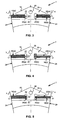
- a first possible embodiment 30(a) of the rotation limiting means 30 in accordance with the invention is presented in the right-hand side of figure 3 .
- This second belt type of the composition of figure 3 being produced with a reduced number of stacked rings 17 in the endless tensile means 16(b) as compared with the first belt type of this particular composition shown on the left-hand side of figure 3 .
- the said rotation freedom of the transverse elements 15 is limited by the relatively narrowly defined radial gap between the respective endless tensile means 16(a) and the top part 21 of the elements 15, in the said second belt type this is additionally realised by the rotation limiting means 30 in the form of a filler ring 30(a) or, possibly, a small number of radially stacked filler rings, provided inside the recesses 20(b) of the transverse elements 15 radially disposed of the respective endless tensile means 16.
- such filler ring 30(a) may be of a relatively cheap, wear resistant and easily treatable material, such as, preferably, a suitable rubber. Possibly also a suitable (low-grade) metal or plastic can be applied.
- the filler ring 30(a) must be able to follow the -varying- trajectory of the push belt (7), so the material must also be bendable at least along its circumference, i.e. in the longitudinal direction.
- the filler ring 30(a) is not intended to have a load-carrying function, i.e.
- the filler ring 30(a) is shown to be provided radially outside the endless tensile means 16(b), it could, in principle, also be provided radially inside thereof between the endless tensile means 16(b) and the bottom part 22 of the transverse elements 15, in which case it should be of a material having a sufficiently small Young's modulus of elasticity to prevent it from being significantly tensioned.
- a second embodiment 30(b) of the rotation limiting means 30 in accordance with the invention which is illustrated in figure 4
- the said second belt type of the composition on the right-hand side of this figure is provided with a locking ring 30(b) placed inside the recess 20(b) of the transverse elements 15 between the pillar part 23 thereof and the endless tensile means 16(b).
- the said rotation freedom of the transverse elements 15 is limited by the relatively narrow axial gap remaining between the endless tensile means 16(b) when being in contact with the respective pulley disc 4, the locking ring 30(b) and the pillar part 21 of the elements 15.
- FIG. 5 A third embodiment 30(c) of the rotation limiting means 30 in accordance with the invention is illustrated in figure 5 .
- the said means 30(c) are incorporated in the design of the endless tensile means 16, which is preferably applied in both belt types of the composition.
- the axial width of at least one ring 17 in both sets 16(a), 16(b) of rings 17 of the endless tensile means 16 is designed to be so large that the said rotation freedom of the transverse element 15 is limited to a desired extend by the relatively narrowly defined axial gap between the pillar part 21 of transverse element 15 and the said at least one ring 17 when being in contact with the respective pulley disc 4.
- a fourth embodiment 30(d) of the rotation limiting means 30 in accordance with the invention is illustrated in figure 6 .
- the said means 30(d) are incorporated in the design of the protrusion 26 and the hole 27 of the elements 15, which is preferably applied in both belt types of the composition.
- the protrusion 26 and the pertaining hole 27 have a non-circular contour such that the said rotation freedom of the transverse elements 15 is limited to a desired extend by the protrusion 26 of one transverse element 15 engaging a side wall of the hole 27 of the next, i.e. adjacent element 15 that is already clamped and aligned between the pulley discs 3, 4.
- the protrusion 26 and hole 27 may have an oval contour, as is illustrated in figure 6 , but they may also be provided with an elongated contour, possibly extending along the entire radial height or axial width of the elements 15.
- a fifth embodiment 30(e) of the rotation limiting means 30 in accordance with the invention is illustrated in figure 7 .
- the said means 30(e) are incorporated in the design of the protrusion 26 and the hole (not visible) of the elements 15, which is preferably applied in both belt types of the composition.
- a set of protrusions 26(a), 26(b) and pertaining holes (not visible) are provided such that the said rotation freedom of the transverse elements 15 is limited to a desired extend by the protrusions 26(a), 26(b) of one transverse element 15 engaging the sides of the holes of the next, i.e. adjacent element 15 that is already clamped and aligned between the pulley discs 3, 4.
- the protrusions 26(a), 26(b) and holes may still be provided with a circular contour.
- FIG 8 a sixth possible embodiment 30(f) of the rotation limiting means 30 in accordance with the invention is illustrated in figure 8 .
- the said second belt type of the composition on the right-hand side of this figure is provided with one or more clips 30(f) along its circumference.
- clip 30(f) functions in much the same manner as the filler ring 30(a) of figure 3 .
- the clip 30(f) surrounds the top part 21 of the element 15 and, on either axial side thereof, is provided with an axially inward extending hook part 31 that hooks around the head part 21 into a respective recess 20(b) and at least partly fills up the said radial gap.
- the clip 30(f) may also be provided with a radially inward extending flange part 32 on either axial side thereof, which flange part 32 confines a respective ring set 16(b) favourably also in the axially direction.
- the clip 30(f) may encompass the entire circumference of the push belt or it may cover over only one or a couple of transverse elements 15 thereof, in which latter case a limited number of clips 30(f) suffices for attaining the desired effect.
- the clip 30(f) is made from an at least slightly resiliently bendable material.
- the push belt is produced in a so-called pre-tensioned state, which involves the tensioning of its endless tensile means even in an unloaded state of the belt, by providing the belt with a continuous array of transverse elements having a combined longitudinal dimension that is greater than a circumference length of the endless tensile means in a non-tensioned state thereof.
Landscapes
- Engineering & Computer Science (AREA)
- General Engineering & Computer Science (AREA)
- Mechanical Engineering (AREA)
- Devices For Conveying Motion By Means Of Endless Flexible Members (AREA)
- Pulleys (AREA)
Claims (12)
- Verfahren zum Herstellen einer Anzahl von Schubriemen (7) jedes von wenigstens zwei unterscheidbaren Typen zur Verwendung in einem stufenlosen Getriebe in einem Kraftfahrzeug, wobei jeder Riementyp ein endloses dehnbares Mittel (16) mit gegenseitig unterschiedlicher radialer Dicke aufweist, wobei das endlose dehnbare Mittel (16) in einer Aussparung (20) von Querelementen (15) eines entsprechenden Riemens (7) aufgenommen ist, wobei die Querelemente (15) verschiebbar auf den endlosen dehnbaren Mitteln (16) in einer Anzahl vorgesehen sind, derart, dass sie eine im Wesentlichen kontinuierliche Anordnung längs des Umfangs der endlosen dehnbaren Mittel (16) bilden, wobei eine Höhe einer entsprechenden Aussparung (20) in der radialen Richtung relativ zu den endlosen dehnbaren Mitteln (16) zwischen einem unteren Abschnitt (21) und einem oberen Abschnitt (22) des entsprechenden Querelements (15) definiert ist, dadurch gekennzeichnet, dass die Riementypen mit Querelementen (15) hergestellt werden, welche die gleiche Höhe der Aussparung (20) aufweisen.
- Verfahren nach Anspruch 1, dadurch gekennzeichnet, dass Drehbegrenzungsmittel (30) zum Begrenzen einer Drehung der Querelemente (15) relativ zu den endlosen dehnbaren Mitteln (16) um deren Längsachse in wenigstens einen ersten der Riementypen integriert sind, wobei der erste Riementyp endlose dehnbare Mittel (16) aufweist, die von einer geringeren Dicke sind als die des zweiten der beiden Riementypen.
- Verfahren nach Anspruch 2, dadurch gekenntzeichnet, dass die Drehbegrenzungsmittel (30) die relative Drehung auf 1 Grad oder weniger, vorzugsweise bis auf einen Bereich von 0,2 bis 0,8 Grad, stärker bevorzugt auf 0,5 Grad begrenzen.
- Verfahren nach einem der Ansprüche 2 oder 3, dadurch gekennzeichnet, dass die Drehbegrenzungsmittel (30) des ersten Riementyps wenigstens eine der folgenden Gruppe von Maßnahmen umfassen:- die Maßnahme, dass ein wenigstens in Längsrichtung biegsamer Füllring (30(a)) innerhalb der Aussparungen (20(b)) der Querelemente (15) radial innerhalb oder außerhalb der entsprechenden endlosen dehnbaren Mittel (16(b)) vorgesehen ist;- die Maßnahme, dass ein wenigstens in Längsrichtung biegsamer Sperrring (30(b)) innerhalb der Aussparungen (20(b)) der Querelemente (15) axial zwischen den endlosen dehnbaren Mitteln (16(b)) und den entsprechenden Stützabschnitten (23) der Elemente (15), die den unteren Abschnitt (21) der entsprechenden Elemente (15) mit ihrem oberen Abschnitt (22) verbinden, vorgesehen ist.- die Maßnahme, dass der Riemen (7) mit einer definierten axialen Lücke zwischen den endlosen dehnbaren Mitteln (16(b)) und einem Stützabschnitt (21) jedes seiner Elemente (15) hergestellt ist, wobei der Stützabschnitt (23) den unteren Abschnitt (21) des entsprechenden Elements (15) mit seinem oberen Abschnitt (22) verbindet, wobei die Drehung der Querelemente (15) durch den Stützabschnitt (23), der mit den endlosen dehnbaren Mitteln (16(b)) in Kontakt ist, begrenzt wird;- die Maßnahme, dass jedes Querelement (15) einen Vorsprung (26), der von einer vorderen Basisfläche (25) des Elements (15) in Längsrichtung des Riemens (7) vorsteht, und ein Loch (27), das an einer hinteren Basisfläche des Elements (15) vorgesehen ist, integriert, wobei der Vorsprung (26) eines Elements (15) mit dem Loch (27) eines entsprechenden benachbarten Elements (15) in Eingriff ist, wobei die Vorsprünge (26) und Löcher (27) mit einer bei Betrachtung in Längsrichtung nicht runden, vorzugsweise elliptischen Kontur (30(d)) versehen sind.- die Maßnahme, dass jedes Querelement (15) zwei Vorsprünge (26(a), 26(b)), die auf einer vorderen Basisfläche (25) der Elemente (15) vorgesehen sind, und zwei Löcher, die in einer hinteren Basisfläche der Elemente (15) vorgesehen sind, integriert, wobei jeder der Vorsprünge (26(a), 26(b)) mit einem zugehörigen Loch eines entsprechenden benachbarten Elements (15) in Eingriff ist;- die Maßnahme, dass der Riemen (7) mit einer Klemmschelle (30(e)) versehen ist, die den oberen Abschnitt (22) wenigstens eines Querelements (15) einschließt und die mit einem sich axial erstreckenden Hakenabschnitt (31) versehen ist, der sich innerhalb der Aussparung (20(b)) des Elements (15) zwischen dem oberen Abschnitt (22) und den endlosen dehnbaren Mitteln (16(b)) erstreckt.- die Maßnahme, dass der Riemen (7) in einem vorgespannten Zustand der endlosen dehnbaren Mittel (16(b)) hergestellt wird, wobei die kombinierte Abmessung in Längsrichtung der kontinuierlichen Anordnung von Querelementen (15), die darin verwendet werden, größer ist als der Umfang der endlosen dehnbaren Mittel (16(b)) in einem ungespannten Zustand.
- Verfahren nach einem der vorhergehenden Ansprüche, dadurch gekennzeichnet, dass die Höhe der Aussparungen (20) so bemessen ist, dass sie wenigstens in radialer Richtung vollständig durch die endlosen dehnbaren Mittel (16) eines ersten der Riementypen eingenommen wird, wobei der erste Riementyp endlose dehnbare Mittel (16) aufweist, die eine größere Dicke aufweisen als die eines zweiten der Riementypen.
- Verfahren nach einem der vorhergehenden Ansprüche, dadurch gekennzeichnet, dass die Riementypen aus Querelementen (15) hergestellt werden, die bei Betrachtung in einem längs orientierten Querschnitt des Riemen (7) eine sich gegenseitig entsprechende äußere Kontur aufweisen.
- Verfahren nach einem der vorhergehenden Ansprüche, dadurch gekennzeichnet, dass die Querelemente (15) der Riementypen eine wenigstens weitgehend gleiche Konstruktion aufweisen.
- Verfahren nach einem der vorhergehenden Ansprüche, dadurch gekennzeichnet, dass die endlosen dehnbaren Mittel (16) aus wenigstens einer Gruppe (16(a), 16(b)) aus radial gestapelten flachen Metallringen (17) bestehen, wobei jeder der Riementypen durch die Anzahl der Ringe (17), die in der wenigstens einen Gruppe (16(a), 16(b)) verwendet werden, unterscheidbar ist.
- Verfahren nach Anspruch 8, dadurch gekennzeichnet, dass die Ringe (17) der Riementypen gleiche Dicke haben.
- Verfahren nach einem der vorhergehenden Ansprüche, dadurch gekennzeichnet, dass jeder der Riementypen hinsichtlich seiner Nenndrehmomentkapazität eine unterschiedliche Spezifikation hat, wobei die Spezifikation mit Bezug auf die Dicke der endlosen dehnbaren Mittel (16), die darin jeweils angewendet werden, bestimmt ist.
- Zusammensetzung von wenigstens zwei Typen von Schubriemen (7), die nach einem Verfahren nach einem der vorhergehenden Ansprüche hergestellt sind.
- Zusammensetzung von zwei Kraftfahrzeugen, wobei jedes Kraftfahrzeug ein stufenloses Getriebe umfasst, das einen Schubriemen (7) umfasst, der versehen ist mit endlosen dehnbaren Mitteln (16), die eine radiale Dicke aufweisen, und mit Querelementen (15), die eine Aussparung (20) definieren, worin sich die endlosen dehnbaren Mittel (16) befinden und wovon eine Höhe in der radialen Richtung zwischen einem unteren Abschnitt (21) und einem oberen Abschnitt (22) des Querelements (15) definiert ist, wobei die endlosen dehnbaren Mittel (16) der Schubriemen (7) der zwei Kraftfahrzeuge eine gegenseitig unterschiedliche radiale Dicke aufweisen, dadurch gekennzeichnet, dass die Querelemente (15) der Schubriemen (7) der zwei Kraftfahrzeuge gleich sind.
Applications Claiming Priority (1)
| Application Number | Priority Date | Filing Date | Title |
|---|---|---|---|
| PCT/NL2004/000908 WO2006068462A1 (en) | 2004-12-24 | 2004-12-24 | Method for manufacturing push belts of distinguishable type and a composition of push belt types |
Publications (2)
| Publication Number | Publication Date |
|---|---|
| EP1831588A1 EP1831588A1 (de) | 2007-09-12 |
| EP1831588B1 true EP1831588B1 (de) | 2012-12-12 |
Family
ID=34960021
Family Applications (1)
| Application Number | Title | Priority Date | Filing Date |
|---|---|---|---|
| EP04808824A Not-in-force EP1831588B1 (de) | 2004-12-24 | 2004-12-24 | Verfahren zur herstellung von schubriemen verschiedener art und zusammensetzung für schubriemenarten |
Country Status (4)
| Country | Link |
|---|---|
| EP (1) | EP1831588B1 (de) |
| JP (1) | JP4809846B2 (de) |
| CN (1) | CN101084388B (de) |
| WO (1) | WO2006068462A1 (de) |
Families Citing this family (2)
| Publication number | Priority date | Publication date | Assignee | Title |
|---|---|---|---|---|
| NL1040570C2 (en) * | 2013-12-24 | 2015-06-26 | Bosch Gmbh Robert | Method for assembling a drive belt with different types of transverse members for a continuously variable transmission and a thus assembled drive belt. |
| NL1042191B1 (en) * | 2016-12-22 | 2018-06-29 | Bosch Gmbh Robert | Drive belt comprising different types of transverse segments for a continuously variable transmission |
Family Cites Families (16)
| Publication number | Priority date | Publication date | Assignee | Title |
|---|---|---|---|---|
| NL7907181A (nl) * | 1979-09-27 | 1981-03-31 | Doornes Transmissie Bv | Drijfriem, voorzien van een aantal in hoofdzaak onvervormbare dwarselementen. |
| JPS5954838A (ja) * | 1982-09-22 | 1984-03-29 | Honda Motor Co Ltd | Vベルト伝動装置 |
| JPS6170245A (ja) * | 1984-09-11 | 1986-04-11 | Nissan Motor Co Ltd | Vベルト |
| JPH0738749Y2 (ja) * | 1991-04-25 | 1995-09-06 | 有限会社マツオエンジニアリング | 無段変速用駆動ベルト |
| NL9101218A (nl) | 1991-07-11 | 1993-02-01 | Doornes Transmissie Bv | Dwarselement voor een drijfriem. |
| NL9300880A (nl) | 1993-05-24 | 1994-12-16 | Doornes Transmissie Bv | Drijfriem. |
| US5439422A (en) * | 1993-05-24 | 1995-08-08 | Van Doorne's Transmissie B.V. | Drive belt |
| JP3554490B2 (ja) * | 1998-09-25 | 2004-08-18 | 本田技研工業株式会社 | 無段変速機用ベルト |
| WO2000028237A1 (fr) * | 1998-11-05 | 2000-05-18 | Fukuju Kogyo Kabushiki Kaisha | Element de courroie metallique, courroie metallique et procede d'assemblage de la courroie metallique |
| DE69922002T2 (de) | 1999-07-27 | 2005-12-22 | Van Doorne's Transmissie B.V. | Treibriemen und Getriebe worin gleiches verwendet ist |
| JP2003532851A (ja) * | 2000-05-09 | 2003-11-05 | ザ ゲイツ コーポレイション | ブロック型cvtベルト |
| NL1015489C2 (nl) * | 2000-06-21 | 2001-12-28 | Doornes Transmissie Bv | Drijfriem en dwarselement voor een drijfriem. |
| JP3630299B2 (ja) * | 2000-07-24 | 2005-03-16 | 同和鉱業株式会社 | 無段変速機の金属ベルト用無端リングの製造方法 |
| JP2002054690A (ja) * | 2000-08-07 | 2002-02-20 | Honda Motor Co Ltd | 無段変速機用ベルト |
| JP2003232408A (ja) * | 2002-02-07 | 2003-08-22 | Koyo Seiko Co Ltd | Vベルト |
| JP4168839B2 (ja) * | 2003-03-06 | 2008-10-22 | 日産自動車株式会社 | 金属ベルト |
-
2004
- 2004-12-24 EP EP04808824A patent/EP1831588B1/de not_active Not-in-force
- 2004-12-24 WO PCT/NL2004/000908 patent/WO2006068462A1/en active Application Filing
- 2004-12-24 CN CN2004800446591A patent/CN101084388B/zh active Active
- 2004-12-24 JP JP2007548107A patent/JP4809846B2/ja active Active
Also Published As
| Publication number | Publication date |
|---|---|
| EP1831588A1 (de) | 2007-09-12 |
| JP4809846B2 (ja) | 2011-11-09 |
| CN101084388A (zh) | 2007-12-05 |
| CN101084388B (zh) | 2010-04-28 |
| WO2006068462A1 (en) | 2006-06-29 |
| JP2008525735A (ja) | 2008-07-17 |
Similar Documents
| Publication | Publication Date | Title |
|---|---|---|
| EP1653119B1 (de) | Riemenscheibe und Riemenantriebseinheit zum Antrieb von Hilfsteilen einer Brennkraftmaschine | |
| US6074317A (en) | Belt for continuously variable transmission with suppressed slip relative to the pulleys | |
| US8038559B2 (en) | Power transmission chain, method for manufacturing power transmission member of the power transmission chain, and power transmission device | |
| KR100348871B1 (ko) | 무단변속기용 벨트 | |
| US6416433B1 (en) | Chain-belt transmission with continuously variable transmission ratio | |
| US6050912A (en) | Continuously variable transmission that changes axial thurst based on transmission ratio | |
| EP1158210A1 (de) | Stufenloses Getriebe, endloser Treibriemen zur Drehmomentübertragung und verstellbare Riemenscheibe | |
| CN101622471A (zh) | 传动皮带 | |
| US11466757B2 (en) | Continuously variable transmission and transmission belt | |
| WO2017108207A1 (en) | Transverse member for a drive belt for a continuously variable transmission | |
| CN103890449B (zh) | 双面动力传递用切边v形带 | |
| JP5693465B2 (ja) | 駆動ベルト | |
| EP1831588B1 (de) | Verfahren zur herstellung von schubriemen verschiedener art und zusammensetzung für schubriemenarten | |
| US9556931B2 (en) | Element for metallic belt | |
| EP1257749B1 (de) | Rippenriemen für cvt-getriebe und rad | |
| KR100877034B1 (ko) | 구동 벨트, 그 연속 밴드 제조 방법 및 구동 벨트가 사용되는 무단 변속기 | |
| US20020123402A1 (en) | Compression type inverted tooth chain | |
| EP1089013B1 (de) | Treibriemen und Getriebe worin gleiches verwendet ist | |
| EP0911541B1 (de) | Antriebsriemen für fest übersetztes Getriebe | |
| JP2008519209A (ja) | 凸面プーリシーブと駆動ベルトを備えた変速機 | |
| EP2187090A1 (de) | Keilriemen für volllast-kraftübertragung | |
| EP1529985B1 (de) | Verfahren zum Betrieb einer stufenlosen Getriebevorrichtung | |
| EP1672245B1 (de) | Zusammengesetzter Treibriemen | |
| US4661088A (en) | Belt for the transmission of motion between pulleys | |
| WO2005090823A1 (en) | Belt for a continuously variable transmission |
Legal Events
| Date | Code | Title | Description |
|---|---|---|---|
| PUAI | Public reference made under article 153(3) epc to a published international application that has entered the european phase |
Free format text: ORIGINAL CODE: 0009012 |
|
| 17P | Request for examination filed |
Effective date: 20070724 |
|
| AK | Designated contracting states |
Kind code of ref document: A1 Designated state(s): AT BE BG CH CY CZ DE DK EE ES FI FR GB GR HU IE IS IT LI LT LU MC NL PL PT RO SE SI SK TR |
|
| 17Q | First examination report despatched |
Effective date: 20071023 |
|
| DAX | Request for extension of the european patent (deleted) | ||
| GRAP | Despatch of communication of intention to grant a patent |
Free format text: ORIGINAL CODE: EPIDOSNIGR1 |
|
| GRAS | Grant fee paid |
Free format text: ORIGINAL CODE: EPIDOSNIGR3 |
|
| GRAA | (expected) grant |
Free format text: ORIGINAL CODE: 0009210 |
|
| AK | Designated contracting states |
Kind code of ref document: B1 Designated state(s): AT BE BG CH CY CZ DE DK EE ES FI FR GB GR HU IE IS IT LI LT LU MC NL PL PT RO SE SI SK TR |
|
| REG | Reference to a national code |
Ref country code: GB Ref legal event code: FG4D |
|
| REG | Reference to a national code |
Ref country code: CH Ref legal event code: EP |
|
| REG | Reference to a national code |
Ref country code: AT Ref legal event code: REF Ref document number: 588480 Country of ref document: AT Kind code of ref document: T Effective date: 20121215 |
|
| REG | Reference to a national code |
Ref country code: IE Ref legal event code: FG4D |
|
| REG | Reference to a national code |
Ref country code: DE Ref legal event code: R096 Ref document number: 602004040413 Country of ref document: DE Effective date: 20130207 |
|
| REG | Reference to a national code |
Ref country code: NL Ref legal event code: T3 |
|
| PG25 | Lapsed in a contracting state [announced via postgrant information from national office to epo] |
Ref country code: ES Free format text: LAPSE BECAUSE OF FAILURE TO SUBMIT A TRANSLATION OF THE DESCRIPTION OR TO PAY THE FEE WITHIN THE PRESCRIBED TIME-LIMIT Effective date: 20130323 Ref country code: SE Free format text: LAPSE BECAUSE OF FAILURE TO SUBMIT A TRANSLATION OF THE DESCRIPTION OR TO PAY THE FEE WITHIN THE PRESCRIBED TIME-LIMIT Effective date: 20121212 Ref country code: FI Free format text: LAPSE BECAUSE OF FAILURE TO SUBMIT A TRANSLATION OF THE DESCRIPTION OR TO PAY THE FEE WITHIN THE PRESCRIBED TIME-LIMIT Effective date: 20121212 Ref country code: LT Free format text: LAPSE BECAUSE OF FAILURE TO SUBMIT A TRANSLATION OF THE DESCRIPTION OR TO PAY THE FEE WITHIN THE PRESCRIBED TIME-LIMIT Effective date: 20121212 |
|
| REG | Reference to a national code |
Ref country code: AT Ref legal event code: MK05 Ref document number: 588480 Country of ref document: AT Kind code of ref document: T Effective date: 20121212 |
|
| REG | Reference to a national code |
Ref country code: LT Ref legal event code: MG4D |
|
| PG25 | Lapsed in a contracting state [announced via postgrant information from national office to epo] |
Ref country code: GR Free format text: LAPSE BECAUSE OF FAILURE TO SUBMIT A TRANSLATION OF THE DESCRIPTION OR TO PAY THE FEE WITHIN THE PRESCRIBED TIME-LIMIT Effective date: 20130313 Ref country code: SI Free format text: LAPSE BECAUSE OF FAILURE TO SUBMIT A TRANSLATION OF THE DESCRIPTION OR TO PAY THE FEE WITHIN THE PRESCRIBED TIME-LIMIT Effective date: 20121212 |
|
| PG25 | Lapsed in a contracting state [announced via postgrant information from national office to epo] |
Ref country code: BE Free format text: LAPSE BECAUSE OF FAILURE TO SUBMIT A TRANSLATION OF THE DESCRIPTION OR TO PAY THE FEE WITHIN THE PRESCRIBED TIME-LIMIT Effective date: 20121212 Ref country code: AT Free format text: LAPSE BECAUSE OF FAILURE TO SUBMIT A TRANSLATION OF THE DESCRIPTION OR TO PAY THE FEE WITHIN THE PRESCRIBED TIME-LIMIT Effective date: 20121212 Ref country code: CY Free format text: LAPSE BECAUSE OF FAILURE TO SUBMIT A TRANSLATION OF THE DESCRIPTION OR TO PAY THE FEE WITHIN THE PRESCRIBED TIME-LIMIT Effective date: 20121212 Ref country code: IS Free format text: LAPSE BECAUSE OF FAILURE TO SUBMIT A TRANSLATION OF THE DESCRIPTION OR TO PAY THE FEE WITHIN THE PRESCRIBED TIME-LIMIT Effective date: 20130412 Ref country code: CZ Free format text: LAPSE BECAUSE OF FAILURE TO SUBMIT A TRANSLATION OF THE DESCRIPTION OR TO PAY THE FEE WITHIN THE PRESCRIBED TIME-LIMIT Effective date: 20121212 Ref country code: EE Free format text: LAPSE BECAUSE OF FAILURE TO SUBMIT A TRANSLATION OF THE DESCRIPTION OR TO PAY THE FEE WITHIN THE PRESCRIBED TIME-LIMIT Effective date: 20121212 Ref country code: BG Free format text: LAPSE BECAUSE OF FAILURE TO SUBMIT A TRANSLATION OF THE DESCRIPTION OR TO PAY THE FEE WITHIN THE PRESCRIBED TIME-LIMIT Effective date: 20130312 Ref country code: MC Free format text: LAPSE BECAUSE OF NON-PAYMENT OF DUE FEES Effective date: 20121231 Ref country code: SK Free format text: LAPSE BECAUSE OF FAILURE TO SUBMIT A TRANSLATION OF THE DESCRIPTION OR TO PAY THE FEE WITHIN THE PRESCRIBED TIME-LIMIT Effective date: 20121212 |
|
| REG | Reference to a national code |
Ref country code: CH Ref legal event code: PL |
|
| PG25 | Lapsed in a contracting state [announced via postgrant information from national office to epo] |
Ref country code: RO Free format text: LAPSE BECAUSE OF FAILURE TO SUBMIT A TRANSLATION OF THE DESCRIPTION OR TO PAY THE FEE WITHIN THE PRESCRIBED TIME-LIMIT Effective date: 20121212 Ref country code: PL Free format text: LAPSE BECAUSE OF FAILURE TO SUBMIT A TRANSLATION OF THE DESCRIPTION OR TO PAY THE FEE WITHIN THE PRESCRIBED TIME-LIMIT Effective date: 20121212 Ref country code: PT Free format text: LAPSE BECAUSE OF FAILURE TO SUBMIT A TRANSLATION OF THE DESCRIPTION OR TO PAY THE FEE WITHIN THE PRESCRIBED TIME-LIMIT Effective date: 20130412 |
|
| REG | Reference to a national code |
Ref country code: IE Ref legal event code: MM4A |
|
| PLBE | No opposition filed within time limit |
Free format text: ORIGINAL CODE: 0009261 |
|
| STAA | Information on the status of an ep patent application or granted ep patent |
Free format text: STATUS: NO OPPOSITION FILED WITHIN TIME LIMIT |
|
| PG25 | Lapsed in a contracting state [announced via postgrant information from national office to epo] |
Ref country code: LI Free format text: LAPSE BECAUSE OF NON-PAYMENT OF DUE FEES Effective date: 20121231 Ref country code: DK Free format text: LAPSE BECAUSE OF FAILURE TO SUBMIT A TRANSLATION OF THE DESCRIPTION OR TO PAY THE FEE WITHIN THE PRESCRIBED TIME-LIMIT Effective date: 20121212 Ref country code: CH Free format text: LAPSE BECAUSE OF NON-PAYMENT OF DUE FEES Effective date: 20121231 Ref country code: IE Free format text: LAPSE BECAUSE OF NON-PAYMENT OF DUE FEES Effective date: 20121224 |
|
| 26N | No opposition filed |
Effective date: 20130913 |
|
| PG25 | Lapsed in a contracting state [announced via postgrant information from national office to epo] |
Ref country code: IT Free format text: LAPSE BECAUSE OF FAILURE TO SUBMIT A TRANSLATION OF THE DESCRIPTION OR TO PAY THE FEE WITHIN THE PRESCRIBED TIME-LIMIT Effective date: 20121212 |
|
| REG | Reference to a national code |
Ref country code: DE Ref legal event code: R097 Ref document number: 602004040413 Country of ref document: DE Effective date: 20130913 |
|
| PG25 | Lapsed in a contracting state [announced via postgrant information from national office to epo] |
Ref country code: TR Free format text: LAPSE BECAUSE OF FAILURE TO SUBMIT A TRANSLATION OF THE DESCRIPTION OR TO PAY THE FEE WITHIN THE PRESCRIBED TIME-LIMIT Effective date: 20121212 |
|
| PG25 | Lapsed in a contracting state [announced via postgrant information from national office to epo] |
Ref country code: LU Free format text: LAPSE BECAUSE OF NON-PAYMENT OF DUE FEES Effective date: 20121224 |
|
| PG25 | Lapsed in a contracting state [announced via postgrant information from national office to epo] |
Ref country code: HU Free format text: LAPSE BECAUSE OF FAILURE TO SUBMIT A TRANSLATION OF THE DESCRIPTION OR TO PAY THE FEE WITHIN THE PRESCRIBED TIME-LIMIT Effective date: 20041224 |
|
| REG | Reference to a national code |
Ref country code: FR Ref legal event code: PLFP Year of fee payment: 12 |
|
| PGFP | Annual fee paid to national office [announced via postgrant information from national office to epo] |
Ref country code: GB Payment date: 20151221 Year of fee payment: 12 |
|
| PGFP | Annual fee paid to national office [announced via postgrant information from national office to epo] |
Ref country code: FR Payment date: 20151218 Year of fee payment: 12 |
|
| PGFP | Annual fee paid to national office [announced via postgrant information from national office to epo] |
Ref country code: NL Payment date: 20161221 Year of fee payment: 13 |
|
| GBPC | Gb: european patent ceased through non-payment of renewal fee |
Effective date: 20161224 |
|
| REG | Reference to a national code |
Ref country code: FR Ref legal event code: ST Effective date: 20170831 |
|
| PG25 | Lapsed in a contracting state [announced via postgrant information from national office to epo] |
Ref country code: FR Free format text: LAPSE BECAUSE OF NON-PAYMENT OF DUE FEES Effective date: 20170102 |
|
| PG25 | Lapsed in a contracting state [announced via postgrant information from national office to epo] |
Ref country code: GB Free format text: LAPSE BECAUSE OF NON-PAYMENT OF DUE FEES Effective date: 20161224 |
|
| REG | Reference to a national code |
Ref country code: NL Ref legal event code: MM Effective date: 20180101 |
|
| PG25 | Lapsed in a contracting state [announced via postgrant information from national office to epo] |
Ref country code: NL Free format text: LAPSE BECAUSE OF NON-PAYMENT OF DUE FEES Effective date: 20180101 |
|
| PGFP | Annual fee paid to national office [announced via postgrant information from national office to epo] |
Ref country code: DE Payment date: 20210217 Year of fee payment: 17 |
|
| REG | Reference to a national code |
Ref country code: DE Ref legal event code: R119 Ref document number: 602004040413 Country of ref document: DE |
|
| PG25 | Lapsed in a contracting state [announced via postgrant information from national office to epo] |
Ref country code: DE Free format text: LAPSE BECAUSE OF NON-PAYMENT OF DUE FEES Effective date: 20220701 |