EP1828610B1 - Variable capacity vane pump with dual control chambers - Google Patents
Variable capacity vane pump with dual control chambers Download PDFInfo
- Publication number
- EP1828610B1 EP1828610B1 EP05820733.3A EP05820733A EP1828610B1 EP 1828610 B1 EP1828610 B1 EP 1828610B1 EP 05820733 A EP05820733 A EP 05820733A EP 1828610 B1 EP1828610 B1 EP 1828610B1
- Authority
- EP
- European Patent Office
- Prior art keywords
- pump
- control
- chamber
- control ring
- ring
- Prior art date
- Legal status (The legal status is an assumption and is not a legal conclusion. Google has not performed a legal analysis and makes no representation as to the accuracy of the status listed.)
- Expired - Lifetime
Links
Images

Classifications
-
- F—MECHANICAL ENGINEERING; LIGHTING; HEATING; WEAPONS; BLASTING
- F04—POSITIVE - DISPLACEMENT MACHINES FOR LIQUIDS; PUMPS FOR LIQUIDS OR ELASTIC FLUIDS
- F04C—ROTARY-PISTON, OR OSCILLATING-PISTON, POSITIVE-DISPLACEMENT MACHINES FOR LIQUIDS; ROTARY-PISTON, OR OSCILLATING-PISTON, POSITIVE-DISPLACEMENT PUMPS
- F04C14/00—Control of, monitoring of, or safety arrangements for, machines, pumps or pumping installations
- F04C14/18—Control of, monitoring of, or safety arrangements for, machines, pumps or pumping installations characterised by varying the volume of the working chamber
- F04C14/22—Control of, monitoring of, or safety arrangements for, machines, pumps or pumping installations characterised by varying the volume of the working chamber by changing the eccentricity between cooperating members
- F04C14/223—Control of, monitoring of, or safety arrangements for, machines, pumps or pumping installations characterised by varying the volume of the working chamber by changing the eccentricity between cooperating members using a movable cam
- F04C14/226—Control of, monitoring of, or safety arrangements for, machines, pumps or pumping installations characterised by varying the volume of the working chamber by changing the eccentricity between cooperating members using a movable cam by pivoting the cam around an eccentric axis
-
- F—MECHANICAL ENGINEERING; LIGHTING; HEATING; WEAPONS; BLASTING
- F04—POSITIVE - DISPLACEMENT MACHINES FOR LIQUIDS; PUMPS FOR LIQUIDS OR ELASTIC FLUIDS
- F04C—ROTARY-PISTON, OR OSCILLATING-PISTON, POSITIVE-DISPLACEMENT MACHINES FOR LIQUIDS; ROTARY-PISTON, OR OSCILLATING-PISTON, POSITIVE-DISPLACEMENT PUMPS
- F04C2/00—Rotary-piston machines or pumps
- F04C2/02—Rotary-piston machines or pumps of arcuate-engagement type, i.e. with circular translatory movement of co-operating members, each member having the same number of teeth or tooth-equivalents
- F04C2/04—Rotary-piston machines or pumps of arcuate-engagement type, i.e. with circular translatory movement of co-operating members, each member having the same number of teeth or tooth-equivalents of internal axis type
-
- F—MECHANICAL ENGINEERING; LIGHTING; HEATING; WEAPONS; BLASTING
- F04—POSITIVE - DISPLACEMENT MACHINES FOR LIQUIDS; PUMPS FOR LIQUIDS OR ELASTIC FLUIDS
- F04C—ROTARY-PISTON, OR OSCILLATING-PISTON, POSITIVE-DISPLACEMENT MACHINES FOR LIQUIDS; ROTARY-PISTON, OR OSCILLATING-PISTON, POSITIVE-DISPLACEMENT PUMPS
- F04C14/00—Control of, monitoring of, or safety arrangements for, machines, pumps or pumping installations
- F04C14/18—Control of, monitoring of, or safety arrangements for, machines, pumps or pumping installations characterised by varying the volume of the working chamber
-
- F—MECHANICAL ENGINEERING; LIGHTING; HEATING; WEAPONS; BLASTING
- F04—POSITIVE - DISPLACEMENT MACHINES FOR LIQUIDS; PUMPS FOR LIQUIDS OR ELASTIC FLUIDS
- F04C—ROTARY-PISTON, OR OSCILLATING-PISTON, POSITIVE-DISPLACEMENT MACHINES FOR LIQUIDS; ROTARY-PISTON, OR OSCILLATING-PISTON, POSITIVE-DISPLACEMENT PUMPS
- F04C2/00—Rotary-piston machines or pumps
- F04C2/30—Rotary-piston machines or pumps having the characteristics covered by two or more groups F04C2/02, F04C2/08, F04C2/22, F04C2/24 or having the characteristics covered by one of these groups together with some other type of movement between co-operating members
- F04C2/34—Rotary-piston machines or pumps having the characteristics covered by two or more groups F04C2/02, F04C2/08, F04C2/22, F04C2/24 or having the characteristics covered by one of these groups together with some other type of movement between co-operating members having the movement defined in groups F04C2/08 or F04C2/22 and relative reciprocation between the co-operating members
- F04C2/344—Rotary-piston machines or pumps having the characteristics covered by two or more groups F04C2/02, F04C2/08, F04C2/22, F04C2/24 or having the characteristics covered by one of these groups together with some other type of movement between co-operating members having the movement defined in groups F04C2/08 or F04C2/22 and relative reciprocation between the co-operating members with vanes reciprocating with respect to the inner member
Definitions
- the present invention relates to a variable capacity vane pump. More specifically, the present invention relates to a variable capacity vane pump in which at least two different equilibrium pressures can be selected between by supplying working fluid to two or more control chambers adjacent the control ring.
- Variable capacity vane pumps are well known and can include a capacity adjusting element, in the form of a pump control ring that can be moved to alter the rotor eccentricity of the pump and hence alter the volumetric capacity of the pump. If the pump is supplying a system with a substantially constant orifice size, such as an automobile engine lubrication system, changing the output volume of the pump is equivalent to changing the pressure produced by the pump.
- Having the ability to alter the volumetric capacity of the pump to maintain an equilibrium pressure is important in environments such as automotive lubrication pumps, wherein the pump will be operated over a range of operating speeds.
- the working fluid e.g. lubricating oil
- a control chamber adjacent the pump control ring the pressure in the control chamber acting to move the control ring, typically against a biasing force from a return spring, to alter the capacity of the pump.
- the equilibrium pressure is determined by the area of the control ring against which the working fluid in the control chamber acts, the pressure of the working fluid supplied to the chamber and the bias force generated by the return spring.
- the equilibrium pressure is selected to be a pressure which is acceptable for the expected operating range of the engine and is thus somewhat of a compromise as, for example, the engine maybe able to operate acceptably at lower operating speeds with a lower working fluid pressure than is required at higher engine operating speeds.
- the engine designers will select an equilibrium pressure for the pump which meets the worst case (high operating speed) conditions.
- the pump will be operating at a higher capacity than necessary for those speeds, wasting energy pumping the surplus, unnecessary, working fluid.
- US 4 531893 A discloses a vane pump having the features of the preamble of claim 1.
- EP 1 350 957 A1 discloses a vane pump having a cam ring, first and second action chambers formed opposite to each other, and a differential pressure control valve for controlling the action chambers.
- US 6 280 150 B1 discloses another solution for a vane pump with a cam ring and two fluid pressure chambers.
- variable capacity vane pump which can provide at least two selectable equilibrium pressures in a reasonably compact pump housing. It is also desired to have a variable capacity vane pump wherein reaction forces on the pivot pin for the pump control ring are reduced.
- variable capacity vane pump having the features of claim 1.
- variable capacity vane pump in accordance with an embodiment of the present invention is indicated generally at 20 in Figures 1 , 2 and 3 .
- pump 20 includes a housing or casing 22 with a front face 24 which is sealed with a pump cover (not shown) and a suitable gasket, to an engine (not shown) or the like for which pump 20 is to supply pressurized working fluid.
- Pump 20 includes a drive shaft 28 which is driven by any suitable means, such as the engine or other mechanism to which the pump is to supply working fluid, to operate pump 20.
- a pump rotor 32 located within a pump chamber 36 is turned with drive shaft 28.
- a series of slidable pump vanes 40 rotate with rotor 32, the outer end of each vane 40 engaging the inner surface of a pump control ring 44, which forms the outer wall of pump chamber 36.
- Pump chamber 36 is divided into a series of working fluid chambers 48, defined by the inner surface of pump control ring 44, pump rotor 32 and vanes 40.
- the pump rotor 32 has an axis of rotation that is eccentric from the center of the pump control ring 44.
- Pump control ring 44 is mounted within casing 22 via a pivot pin 52 which allows the center of pump control ring 44 to be moved relative to the center of rotor 32.
- the volume of working fluid chambers 48 changes as the chambers 48 rotate around pump chamber 36, with their volume becoming larger at the low pressure side (the left hand side of pump chamber 36 in Figure 1 ) of pump 20 and smaller at the high pressure side (the right hand side of pump chamber 36 in Figure 1 ) of pump 20.
- This change in volume of working fluid chambers 48 generates the pumping action of pump 20, drawing working fluid from an inlet port 50 and pressurizing and delivering it to an outlet port 54.
- pump control ring 44 By moving pump control ring 44 about pivot pin 52 the amount of eccentricity, relative to pump rotor 32, can be changed to vary the amount by which the volume of working fluid chambers 48 change from the low pressure side of pump 20 to the high pressure side of pump 20, thus changing the volumetric capacity of the pump.
- a return spring 56 biases pump control ring 44 to the position, shown in Figures 1 and 2 , wherein the pump has a maximum eccentricity.
- pump 20 includes two control chambers 60 and 64, best seen in Figure 3 , to control pump ring 44.
- Control chamber 60 the rightmost hatched area in Figure 3 , is formed between pump casing 22, pump control ring 44, pivot pin 52 and a resilient seal 68, mounted on pump control ring 44 and abutting casing 22.
- control chamber 60 is in direct fluid communication with pump outlet 54 such that pressurized working fluid from pump 20 which is supplied to pump outlet 54 also fills control chamber 60.
- control chamber 60 need not be in direct fluid communication with pump outlet 54 and can instead be supplied from any suitable source of working fluid, such as from an oil gallery in an automotive engine being supplied by pump 20.
- Pressurized working fluid in control chamber 60 acts against pump control ring 44 and, when the force on pump control ring 44 resulting from the pressure of the pressurized working is sufficient to overcome the biasing force of return spring 56, pump control ring 44 pivots about pivot pin 52, as indicated by arrow 72 in Figure 3 , to reduce the eccentricity of pump 20.
- pump control ring 44 pivots about pivot pin 52, in the direction opposite to that indicated by arrow 72, to increase the eccentricity of pump 20.
- Pump 20 further includes a second control chamber 64, the leftmost hatched area in Figure 3 , which is formed between pump casing 22, pump control ring 44, resilient seal 68 and a second resilient seal 76.
- Resilient seal 76 abuts the wall of pump casing 22 to separate control chamber 64 from pump inlet 50 and resilient seal 68 separates chamber 64 from chamber 60.
- Control chamber 64 is supplied with pressurized working fluid through a control port 80.
- Control port 80 can be supplied with pressurized working fluid from any suitable source, including pump outlet 54 or a working fluid gallery in the engine or other device supplied from pump 20.
- a control mechanism (not shown) such as a solenoid operated valve or diverter mechanism is employed to selectively supply working fluid to chamber 64 through control port 80, as discussed below.
- pressurized working fluid supplied to control chamber 64 from control port 80 acts against pump control ring 44.
- pump 20 can operate in a conventional manner to achieve an equilibrium pressure as pressurized working fluid supplied to pump outlet 54 also fills control chamber 60.
- the pressure of the working fluid is greater than the equilibrium pressure, the force created by the pressure of the supplied working fluid over the portion of pump control ring 44 within chamber 60 will overcome the force of return spring 56 to move pump ring 44 to decrease the volumetric capacity of pump 20.
- the force of return spring 56 will exceed the force created by the pressure of the supplied working fluid over the portion of pump control ring 44 within chamber 60 and return spring 56 will to move pump ring 44 to increase the volumetric capacity of pump 20.
- pump 20 can be operated at a second equilibrium pressure. Specifically, by selectively supplying pressurized working fluid to control chamber 64, via control port 80, a second equilibrium pressure can be selected.
- a solenoid-operated valve controlled by an engine control system can supply pressurized working fluid to control chamber 64, via control port 80, such that the force created by the pressurized working fluid on the relevant area of pump control ring 44 within chamber 64 is added to the force created by the pressurized working fluid in control chamber 60, thus moving pump control ring 44 further than would otherwise be the case, to establish a new, lower, equilibrium pressure for pump 20.
- pressurized working fluid can be provided to both chambers 60 and 64 and pump ring 44 will be moved to a position wherein the capacity of the pump produces a first, lower, equilibrium pressure which is acceptable at low operating speeds.
- control mechanism can operate to remove the supply of pressurized working fluid to control chamber 64, thus moving pump ring 44, via return spring 56, to establish a second equilibrium pressure for pump 20, which second equilibrium pressure is higher than the first equilibrium pressure.
- chamber 60 is in fluid communication with pump outlet 54
- a control mechanism such as a solenoid operated valve or a diverter mechanism can be employed to selectively supply working fluid to chamber 60 through the control port.
- a control mechanism such as a solenoid operated valve or a diverter mechanism can be employed to selectively supply working fluid to chamber 60 through the control port.
- pump casing 22 and pump control ring 44 can be fabricated to form one or more additional control chambers, as necessary.
- Pump 20 offers a further advantage over conventional vane pumps such as pump 200 shown in Figure 4 .
- conventional vane pumps such as pump 200
- the low pressure fluid 204 in the pump chamber exerts a force on pump ring 216 as does the high pressure fluid 208 in the pump chamber.
- These forces result in a significant net force 212 on the pump control ring 216 and this force is largely carried by pivot pin 220 which is located at the point where force 212 acts.
- pivot pin 220 carries large reaction forces 240 and 244, to counter net forces 212 and 228 respectively, and these forces can result in undesirable wear of pivot pin 220 over time and/or "stiction" of pump control ring 216, wherein it does not pivot smoothly about pivot pin 220, making fine control of pump 200 more difficult to achieve.
- control chamber 60 is positioned such that force 316 includes a horizontal component, which acts to oppose force 308 and thus reduce reaction force 312 on pivot pin 52.
- the vertical (with respect to the orientation shown in the Figure) component of force 316 does result in a vertical reaction force 320 on pivot pin 52 but, as mentioned above, force 316 is of less magnitude than would be the case with conventional pumps and the vertical reaction force 320 is also reduced by a vertical component of the biasing force 324 produced by return spring 56
- control chamber 60 and return spring 56 results in reduced reaction forces on pivot pin 52 and can improve the operating lifetime of pump 20 and can reduce "stiction" of pump control ring 44 to allow smoother control of pump 20.
- this unique positioning is not limited to use in variable capacity vane pumps with two or more equilibrium pressures and can be employed with variable capacity vane pumps with single equilibrium pressures.
Landscapes
- Engineering & Computer Science (AREA)
- Mechanical Engineering (AREA)
- General Engineering & Computer Science (AREA)
- Rotary Pumps (AREA)
- Details And Applications Of Rotary Liquid Pumps (AREA)
Description
- The present invention relates to a variable capacity vane pump. More specifically, the present invention relates to a variable capacity vane pump in which at least two different equilibrium pressures can be selected between by supplying working fluid to two or more control chambers adjacent the control ring.
- Variable capacity vane pumps are well known and can include a capacity adjusting element, in the form of a pump control ring that can be moved to alter the rotor eccentricity of the pump and hence alter the volumetric capacity of the pump. If the pump is supplying a system with a substantially constant orifice size, such as an automobile engine lubrication system, changing the output volume of the pump is equivalent to changing the pressure produced by the pump.
- Having the ability to alter the volumetric capacity of the pump to maintain an equilibrium pressure is important in environments such as automotive lubrication pumps, wherein the pump will be operated over a range of operating speeds. In such environments, to maintain an equilibrium pressure it is known to employ a feedback supply of the working fluid (e.g. lubricating oil) from the output of the pump to a control chamber adjacent the pump control ring, the pressure in the control chamber acting to move the control ring, typically against a biasing force from a return spring, to alter the capacity of the pump.
- When the pressure at the output of the pump increases, such as when the operating speed of the pump increases, the increased pressure is applied to the control ring to overcome the bias of the return spring and to move the control ring to reduce the capacity of the pump, thus reducing the output volume and hence the pressure at the output of the pump.
- Conversely, as the pressure at the output of the pump drops, such as when the operating speed of the pump decreases, the decreased pressure applied to the control chamber adjacent the control ring allows the bias of the return spring to move the control ring to increase the capacity of the pump, raising the output volume and hence pressure of the pump. In this manner, an equilibrium pressure is obtained at the output of the pump.
- The equilibrium pressure is determined by the area of the control ring against which the working fluid in the control chamber acts, the pressure of the working fluid supplied to the chamber and the bias force generated by the return spring.
- Conventionally, the equilibrium pressure is selected to be a pressure which is acceptable for the expected operating range of the engine and is thus somewhat of a compromise as, for example, the engine maybe able to operate acceptably at lower operating speeds with a lower working fluid pressure than is required at higher engine operating speeds. In order to prevent undue wear or other damage to the engine, the engine designers will select an equilibrium pressure for the pump which meets the worst case (high operating speed) conditions. Thus, at lower speeds, the pump will be operating at a higher capacity than necessary for those speeds, wasting energy pumping the surplus, unnecessary, working fluid.
-
US 4 531893 A discloses a vane pump having the features of the preamble of claim 1. -
EP 1 350 957 A1 discloses a vane pump having a cam ring, first and second action chambers formed opposite to each other, and a differential pressure control valve for controlling the action chambers. -
US 6 280 150 B1 discloses another solution for a vane pump with a cam ring and two fluid pressure chambers. - It is desired to have a variable capacity vane pump which can provide at least two selectable equilibrium pressures in a reasonably compact pump housing. It is also desired to have a variable capacity vane pump wherein reaction forces on the pivot pin for the pump control ring are reduced.
- It is an object of the present invention to provide a novel variable capacity vane pump which obviates or mitigates at least one disadvantage of the prior art.
- According to the present invention, there is provided a variable capacity vane pump having the features of claim 1.
- Preferred embodiments of the present invention will now be described, by way of example only, with reference to the attached Figures, wherein:
-
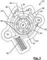
Figure 1 is a front view of a variable capacity vane pump in accordance with the present invention with the control ring positioned for maximum rotor eccentricity; -
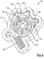
Figure 2 is a front perspective view of the pump ofFigure 1 with the control ring positioned for maximum rotor eccentricity; -
Figure 3 is the a front view of the pump ofFigure 1 with the control ring position for minimum eccentricity and wherein the areas of the pump control chambers are in hatched line; -
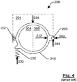
Figure 4 shows a schematic representation of a prior art variable capacity vane pump; and -
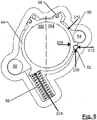
Figure 5 shows a front view of the pump ofFigure 1 wherein the rotor and vanes have been removed to illustrate the forces within the pump. - A variable capacity vane pump in accordance with an embodiment of the present invention is indicated generally at 20 in
Figures 1 ,2 and3 . - Referring now to
Figures 1 ,2 and3 ,pump 20 includes a housing orcasing 22 with afront face 24 which is sealed with a pump cover (not shown) and a suitable gasket, to an engine (not shown) or the like for whichpump 20 is to supply pressurized working fluid. -
Pump 20 includes adrive shaft 28 which is driven by any suitable means, such as the engine or other mechanism to which the pump is to supply working fluid, to operatepump 20. Asdrive shaft 28 is rotated, apump rotor 32 located within apump chamber 36 is turned withdrive shaft 28. A series of slidable pump vanes 40 rotate withrotor 32, the outer end of eachvane 40 engaging the inner surface of apump control ring 44, which forms the outer wall ofpump chamber 36.Pump chamber 36 is divided into a series ofworking fluid chambers 48, defined by the inner surface ofpump control ring 44,pump rotor 32 andvanes 40. Thepump rotor 32 has an axis of rotation that is eccentric from the center of thepump control ring 44. -
Pump control ring 44 is mounted withincasing 22 via apivot pin 52 which allows the center ofpump control ring 44 to be moved relative to the center ofrotor 32. As the center ofpump control ring 44 is located eccentrically with respect to the center ofpump rotor 32 and each of the interior ofpump control ring 44 andpump rotor 32 are circular in shape, the volume ofworking fluid chambers 48 changes as thechambers 48 rotate aroundpump chamber 36, with their volume becoming larger at the low pressure side (the left hand side ofpump chamber 36 inFigure 1 ) ofpump 20 and smaller at the high pressure side (the right hand side ofpump chamber 36 inFigure 1 ) ofpump 20. This change in volume ofworking fluid chambers 48 generates the pumping action ofpump 20, drawing working fluid from aninlet port 50 and pressurizing and delivering it to anoutlet port 54. - By moving
pump control ring 44 aboutpivot pin 52 the amount of eccentricity, relative topump rotor 32, can be changed to vary the amount by which the volume ofworking fluid chambers 48 change from the low pressure side ofpump 20 to the high pressure side ofpump 20, thus changing the volumetric capacity of the pump. Areturn spring 56 biasespump control ring 44 to the position, shown inFigures 1 and2 , wherein the pump has a maximum eccentricity. - As mentioned above, it is known to provide a control chamber adjacent a pump control ring and a return spring to move the pump ring of a variable capacity vane pump to establish an equilibrium output volume, and its related equilibrium pressure.
- However, in accordance with the present invention,
pump 20 includes twocontrol chambers Figure 3 , to controlpump ring 44.Control chamber 60, the rightmost hatched area inFigure 3 , is formed betweenpump casing 22,pump control ring 44,pivot pin 52 and aresilient seal 68, mounted onpump control ring 44 and abuttingcasing 22. In the illustrated embodiment,control chamber 60 is in direct fluid communication withpump outlet 54 such that pressurized working fluid frompump 20 which is supplied topump outlet 54 also fillscontrol chamber 60. - As will be apparent to those of skill in the art,
control chamber 60 need not be in direct fluid communication withpump outlet 54 and can instead be supplied from any suitable source of working fluid, such as from an oil gallery in an automotive engine being supplied bypump 20. - Pressurized working fluid in
control chamber 60 acts againstpump control ring 44 and, when the force onpump control ring 44 resulting from the pressure of the pressurized working is sufficient to overcome the biasing force ofreturn spring 56,pump control ring 44 pivots aboutpivot pin 52, as indicated byarrow 72 inFigure 3 , to reduce the eccentricity ofpump 20. When the pressure of the pressurized working is not sufficient to overcome the biasing force ofreturn spring 56,pump control ring 44 pivots aboutpivot pin 52, in the direction opposite to that indicated byarrow 72, to increase the eccentricity ofpump 20. -
Pump 20 further includes asecond control chamber 64, the leftmost hatched area inFigure 3 , which is formed betweenpump casing 22,pump control ring 44,resilient seal 68 and a secondresilient seal 76.Resilient seal 76 abuts the wall ofpump casing 22 to separatecontrol chamber 64 frompump inlet 50 andresilient seal 68 separateschamber 64 fromchamber 60. -
Control chamber 64 is supplied with pressurized working fluid through acontrol port 80.Control port 80 can be supplied with pressurized working fluid from any suitable source, includingpump outlet 54 or a working fluid gallery in the engine or other device supplied frompump 20. A control mechanism (not shown) such as a solenoid operated valve or diverter mechanism is employed to selectively supply working fluid tochamber 64 throughcontrol port 80, as discussed below. As was the case withcontrol chamber 60, pressurized working fluid supplied tocontrol chamber 64 fromcontrol port 80 acts againstpump control ring 44. - As should now be apparent,
pump 20 can operate in a conventional manner to achieve an equilibrium pressure as pressurized working fluid supplied to pumpoutlet 54 also fillscontrol chamber 60. When the pressure of the working fluid is greater than the equilibrium pressure, the force created by the pressure of the supplied working fluid over the portion ofpump control ring 44 withinchamber 60 will overcome the force ofreturn spring 56 to movepump ring 44 to decrease the volumetric capacity ofpump 20. Conversely, when the pressure of the working fluid is less than the equilibrium pressure, the force ofreturn spring 56 will exceed the force created by the pressure of the supplied working fluid over the portion ofpump control ring 44 withinchamber 60 and returnspring 56 will to movepump ring 44 to increase the volumetric capacity ofpump 20. - However, unlike with conventional pumps,
pump 20 can be operated at a second equilibrium pressure. Specifically, by selectively supplying pressurized working fluid tocontrol chamber 64, viacontrol port 80, a second equilibrium pressure can be selected. For example, a solenoid-operated valve controlled by an engine control system, can supply pressurized working fluid tocontrol chamber 64, viacontrol port 80, such that the force created by the pressurized working fluid on the relevant area ofpump control ring 44 withinchamber 64 is added to the force created by the pressurized working fluid incontrol chamber 60, thus movingpump control ring 44 further than would otherwise be the case, to establish a new, lower, equilibrium pressure forpump 20. - As an example, at low operating speeds of
pump 20, pressurized working fluid can be provided to bothchambers pump ring 44 will be moved to a position wherein the capacity of the pump produces a first, lower, equilibrium pressure which is acceptable at low operating speeds. - When
pump 20 is driven at higher speeds, the control mechanism can operate to remove the supply of pressurized working fluid tocontrol chamber 64, thus movingpump ring 44, viareturn spring 56, to establish a second equilibrium pressure forpump 20, which second equilibrium pressure is higher than the first equilibrium pressure. - While in the illustrated
embodiment chamber 60 is in fluid communication withpump outlet 54, it will be apparent to those of skill in the art that it is a simple matter, if desired, to alter the design ofcontrol chamber 60 such that it is supplied with pressurized working fluid from a control port, similar tocontrol port 80, rather than frompump outlet 54. In such a case, a control mechanism (not shown) such as a solenoid operated valve or a diverter mechanism can be employed to selectively supply working fluid tochamber 60 through the control port. As the area ofcontrol ring 44 within each ofcontrol chambers chamber 60, to controlchamber 64 or to both ofcontrol chambers - As will also be apparent to those of skill in the art, should additional equilibrium pressures be desired, pump
casing 22 andpump control ring 44 can be fabricated to form one or more additional control chambers, as necessary. -
Pump 20 offers a further advantage over conventional vane pumps such aspump 200 shown inFigure 4 . In conventional vane pumps such aspump 200, thelow pressure fluid 204 in the pump chamber exerts a force onpump ring 216 as does thehigh pressure fluid 208 in the pump chamber. These forces result in a significantnet force 212 on thepump control ring 216 and this force is largely carried bypivot pin 220 which is located at the point whereforce 212 acts. - Further, the high pressure fluid within the outlet port 224 (indicated in dashed line), acting over the area of
pump ring 216 betweenpivot pin 220 andresilient seal 222, also results in asignificant force 228 onpump control ring 216. Whileforce 228 is somewhat offset by theforce 232 ofreturn spring 236, the net offorces 228less force 232 can still be significant and this net force is also largely carried bypivot pin 220. - Thus
pivot pin 220 carrieslarge reaction forces net forces pivot pin 220 over time and/or "stiction" ofpump control ring 216, wherein it does not pivot smoothly aboutpivot pin 220, making fine control ofpump 200 more difficult to achieve. - As shown in
Figure 5 , thelow pressure side 300 andhigh pressure side 304 ofpump 20 result in anet force 308 which is applied to pumpcontrol ring 44 almost directly uponpivot pin 52 and a corresponding reaction force, shown as a horizontal (with respect to the orientation shown in the Figure)force 312, is produced onpivot pin 52. Unlike conventional variable capacity vane pumps such aspump 200, inpump 20resilient seal 68 is located relatively closely to pivotpin 52 to reduce the area ofpump control ring 44 upon which the pressurized working fluid incontrol chamber 60 acts and thus to significantly reduce the magnitude of theforce 316 produced onpump control ring 44. - Further,
control chamber 60 is positioned such thatforce 316 includes a horizontal component, which acts to opposeforce 308 and thus reducereaction force 312 onpivot pin 52. The vertical (with respect to the orientation shown in the Figure) component offorce 316 does result in avertical reaction force 320 onpivot pin 52 but, as mentioned above,force 316 is of less magnitude than would be the case with conventional pumps and thevertical reaction force 320 is also reduced by a vertical component of the biasingforce 324 produced byreturn spring 56 - Thus, the unique positioning of
control chamber 60 and returnspring 56, with respect to pivotpin 52, results in reduced reaction forces onpivot pin 52 and can improve the operating lifetime ofpump 20 and can reduce "stiction" ofpump control ring 44 to allow smoother control ofpump 20. As will be apparent to those of skill in the art, this unique positioning is not limited to use in variable capacity vane pumps with two or more equilibrium pressures and can be employed with variable capacity vane pumps with single equilibrium pressures. - The above-described embodiments of the invention are intended to be examples of the present invention and alterations and modifications may be effected thereto, by those of skill in the art, without departing from the scope of the invention which is defined solely by the claims appended hereto.
Claims (7)
- A variable capacity vane pump (20) having a pump control ring (44) which is moveable to alter the capacity of the pump, the pump being operable at at least two selected equilibrium pressures, comprising:a pump casing (22) having a pump chamber (36) therein, said pump chamber (36) having an inlet port (50) and an outlet port (54);a pump control ring (44) pivotable within the pump chamber (36) to alter the capacity of the pump;a vane pump rotor (32) rotatably mounted within the pump control ring (44), said vane pump rotor (32) having a plurality of slidably mounted vanes (40) engaging an inside surface of said pump control ring (44), the vane pump rotor (32) having an axis of rotation eccentric from a centre of said pump control ring (44), the vane pump rotor (32) rotates to pressurize fluid as the fluid moves from the inlet port (50) to the outlet port (54);a first control chamber (60) between the pump casing (22) and the pump control ring (44), the first control chamber (60) operable to receive pressurized fluid to create a force on the pump control ring (44);a second control chamber (64) between the pump casing (22) and the pump control ring (44), the second control chamber (64) selectively operable to receive pressurized fluid to create a force to pivot the pump control ring (44) to reduce the volumetric capacity of the pump; anda return spring (56) acting between the pump control ring (44) and the casing (22) to bias the pump control ring (44) towards a position of maximum volumetric capacity;characterized in that
the first control chamber (60) is positioned such that the force created by the pressurized fluid received in the first control chamber (60) pivots the pump control ring (44) to reduce the volumetric capacity of the pump, the return spring (56) acting against the pivoting force of the first and second control chambers (60, 64) to establish an equilibrium pressure. - The variable capacity pump (20) of claim 1 wherein pressurized fluid is supplied to the first control chamber (60) when the pump is operating and pressurized fluid is supplied to a second control chamber (64) only in response to a signal from a control system.
- The variable capacity pump (20) of claim 1 wherein the second control chamber (64) is supplied with pressurized fluid from a control port (80).
- The variable capacity pump of claim 1 wherein the first control chamber (60) is in fluid communication with the outlet port (54) and receives the pressurized fluid therefrom.
- The variable capacity pump of claim 1 wherein the second chamber (64)is formed by the pump casing (22), the pump control ring (44) and first and second resilient seals (68, 76) acting between the pump control ring (44) and the pump casing (22).
- The variable capacity pump of claim 1 wherein the area of the pump control ring (44) within each of the first and second control chambers (60,64) differs.
- The variable capacity pump of claim 1 further comprising a third control chamber operable to receive pressurized fluid to create a force to move the pump control ring (44) to reduce the volumetric capacity of the pump.
Priority Applications (1)
| Application Number | Priority Date | Filing Date | Title |
|---|---|---|---|
| EP16204586.8A EP3165769B1 (en) | 2004-12-22 | 2005-12-21 | Method of operating a variable capacity pump |
Applications Claiming Priority (2)
| Application Number | Priority Date | Filing Date | Title |
|---|---|---|---|
| US63918504P | 2004-12-22 | 2004-12-22 | |
| PCT/CA2005/001946 WO2006066405A1 (en) | 2004-12-22 | 2005-12-21 | Variable capacity vane pump with dual control chambers |
Related Child Applications (1)
| Application Number | Title | Priority Date | Filing Date |
|---|---|---|---|
| EP16204586.8A Division EP3165769B1 (en) | 2004-12-22 | 2005-12-21 | Method of operating a variable capacity pump |
Publications (3)
| Publication Number | Publication Date |
|---|---|
| EP1828610A1 EP1828610A1 (en) | 2007-09-05 |
| EP1828610A4 EP1828610A4 (en) | 2012-10-24 |
| EP1828610B1 true EP1828610B1 (en) | 2016-12-21 |
Family
ID=36601323
Family Applications (2)
| Application Number | Title | Priority Date | Filing Date |
|---|---|---|---|
| EP05820733.3A Expired - Lifetime EP1828610B1 (en) | 2004-12-22 | 2005-12-21 | Variable capacity vane pump with dual control chambers |
| EP16204586.8A Expired - Lifetime EP3165769B1 (en) | 2004-12-22 | 2005-12-21 | Method of operating a variable capacity pump |
Family Applications After (1)
| Application Number | Title | Priority Date | Filing Date |
|---|---|---|---|
| EP16204586.8A Expired - Lifetime EP3165769B1 (en) | 2004-12-22 | 2005-12-21 | Method of operating a variable capacity pump |
Country Status (9)
| Country | Link |
|---|---|
| US (3) | US7794217B2 (en) |
| EP (2) | EP1828610B1 (en) |
| JP (3) | JP5116483B2 (en) |
| KR (1) | KR101177595B1 (en) |
| CN (1) | CN100520069C (en) |
| CA (2) | CA2762087C (en) |
| DE (1) | DE202005021925U1 (en) |
| TR (1) | TR201819627T4 (en) |
| WO (1) | WO2006066405A1 (en) |
Families Citing this family (75)
| Publication number | Priority date | Publication date | Assignee | Title |
|---|---|---|---|---|
| US9181803B2 (en) * | 2004-12-22 | 2015-11-10 | Magna Powertrain Inc. | Vane pump with multiple control chambers |
| WO2006066405A1 (en) | 2004-12-22 | 2006-06-29 | Magna Powertrain Inc. | Variable capacity vane pump with dual control chambers |
| AT502189B1 (en) * | 2005-07-29 | 2007-02-15 | Miba Sinter Holding Gmbh & Co | VANE PUMP |
| EP1820935A1 (en) * | 2006-02-15 | 2007-08-22 | Magna Powertrain Inc. | Vane pump housing |
| US20070224067A1 (en) * | 2006-03-27 | 2007-09-27 | Manfred Arnold | Variable displacement sliding vane pump |
| US8057201B2 (en) * | 2006-05-04 | 2011-11-15 | Magna Powertrain Inc. | Variable displacement vane pump with dual control chambers |
| EP2038554B1 (en) * | 2006-07-06 | 2015-08-19 | Magna Powertrain Inc. | A variable capacity pump with dual springs |
| US8430645B2 (en) | 2006-09-08 | 2013-04-30 | Slw Automotive Inc. | Two stage pressure regulation system for variable displacement hydraulic pumps |
| CA2663123C (en) | 2006-09-26 | 2016-10-25 | Magna Powertrain Inc. | Control system and method for pump output pressure control |
| US8297943B2 (en) * | 2006-11-06 | 2012-10-30 | Magna Powertrain, Inc. | Pump control using overpressure source |
| DE102006061326B4 (en) * | 2006-12-22 | 2012-02-16 | Mahle International Gmbh | Positioning device for a volume-adjustable cell pump |
| CN103541898B (en) * | 2008-04-25 | 2015-11-18 | 麦格纳动力系有限公司 | There is the variable displacement vane pump of the exhaust port of enhancing |
| GB2466274B (en) * | 2008-12-18 | 2015-05-27 | Gm Global Tech Operations Inc | A lubrication system for an internal combustion engine provided with a variable displacement oil pump and control method therefor |
| DE102009004456B4 (en) * | 2009-01-13 | 2012-01-19 | Mahle International Gmbh | Variable volume cell pump with swiveling spool |
| KR101020500B1 (en) * | 2009-02-03 | 2011-03-09 | 마그나파워트레인코리아 주식회사 | Oil Pump for Automatic Transmission |
| JP5174720B2 (en) | 2009-03-09 | 2013-04-03 | 日立オートモティブシステムズ株式会社 | Variable displacement pump |
| JP5145271B2 (en) * | 2009-03-11 | 2013-02-13 | 日立オートモティブシステムズ株式会社 | Variable capacity oil pump |
| EP2253847B1 (en) | 2009-05-18 | 2019-07-03 | Pierburg Pump Technology GmbH | Variable capacity lubricant vane pump |
| KR101526596B1 (en) * | 2009-10-27 | 2015-06-05 | 현대자동차주식회사 | Variable Capacity Pump |
| KR101491183B1 (en) * | 2009-12-02 | 2015-02-09 | 현대자동차주식회사 | Variable oil pump with reduced pressure |
| JP5364606B2 (en) | 2010-01-29 | 2013-12-11 | 日立オートモティブシステムズ株式会社 | Vane pump |
| US8499738B2 (en) | 2010-03-01 | 2013-08-06 | GM Global Technology Operations LLC | Control systems for a variable capacity engine oil pump |
| DE102010009839A1 (en) * | 2010-03-02 | 2011-09-08 | Schwäbische Hüttenwerke Automotive GmbH | Adjustable pump e.g. adjustable vane pump, has chamber arranged adjacent to stator, where medium is acted upon chamber, and pressing force of medium acts against holding force of holder unit, and chamber is arranged at pump outlet |
| EP2375073A1 (en) * | 2010-03-31 | 2011-10-12 | Pierburg Pump Technology GmbH | Sealing for the control chamber of a variable displacement lubricant pump |
| EP2577067B1 (en) | 2010-05-28 | 2018-03-21 | Pierburg Pump Technology GmbH | Variable displacement lubricant pump |
| DE102010023068B4 (en) * | 2010-06-08 | 2025-11-27 | Mahle International Gmbh | vane pump |
| EP2598752B1 (en) * | 2010-07-29 | 2015-07-29 | Pierburg Pump Technology GmbH | Variable-displacement lubricant vane pump |
| US8734122B2 (en) | 2010-09-09 | 2014-05-27 | GM Global Technology Operations LLC | Control and diagnostic systems for a variable capacity engine oil pump and an engine oil pressure sensor |
| JP5278779B2 (en) | 2010-12-21 | 2013-09-04 | アイシン精機株式会社 | Oil pump |
| DE102011076197A1 (en) * | 2011-05-20 | 2012-11-22 | Ford Global Technologies, Llc | Internal combustion engine with oil circuit and method for operating such an internal combustion engine |
| CN102410214A (en) * | 2011-11-03 | 2012-04-11 | 湖南机油泵股份有限公司 | Middle-section variable high-speed pressure limiting three-section pressure feedback variable-displacement vane pump and variable-displacement method |
| DE102011086175B3 (en) * | 2011-11-11 | 2013-05-16 | Schwäbische Hüttenwerke Automotive GmbH | Rotary pump with improved sealing |
| JP5688003B2 (en) | 2011-12-21 | 2015-03-25 | 日立オートモティブシステムズ株式会社 | Variable displacement oil pump |
| JP5679958B2 (en) | 2011-12-21 | 2015-03-04 | 日立オートモティブシステムズ株式会社 | Variable displacement pump |
| DE102012208244A1 (en) * | 2012-05-16 | 2013-11-21 | Zf Friedrichshafen Ag | Vehicle transmission with a hydrodynamic retarder |
| US9206800B2 (en) * | 2012-05-18 | 2015-12-08 | Magna Powertrain Inc. | Multiple stage passive variable displacement vane pump |
| DE102012210899A1 (en) * | 2012-06-26 | 2014-01-02 | Mahle International Gmbh | Hydraulic conveyor and hydraulic system |
| JP6082548B2 (en) | 2012-09-07 | 2017-02-15 | 日立オートモティブシステムズ株式会社 | Variable displacement pump |
| JP6050640B2 (en) | 2012-09-07 | 2016-12-21 | 日立オートモティブシステムズ株式会社 | Variable displacement oil pump |
| DE112013004886B4 (en) * | 2012-10-05 | 2016-09-15 | Magna Powertrain Bad Homburg GmbH | Pump with adjustable delivery volume |
| CN103775811A (en) * | 2012-10-24 | 2014-05-07 | 北京汽车动力总成有限公司 | Oil pump with variable displacement |
| JP6004919B2 (en) | 2012-11-27 | 2016-10-12 | 日立オートモティブシステムズ株式会社 | Variable displacement oil pump |
| JP6006098B2 (en) | 2012-11-27 | 2016-10-12 | 日立オートモティブシステムズ株式会社 | Variable displacement pump |
| JP5499151B2 (en) * | 2012-12-27 | 2014-05-21 | 日立オートモティブシステムズ株式会社 | Variable displacement pump |
| US9109597B2 (en) | 2013-01-15 | 2015-08-18 | Stackpole International Engineered Products Ltd | Variable displacement pump with multiple pressure chambers where a circumferential extent of a first portion of a first chamber is greater than a second portion |
| JP5960616B2 (en) * | 2013-01-21 | 2016-08-02 | トヨタ自動車株式会社 | Variable displacement oil pump |
| CN103089615B (en) * | 2013-02-04 | 2015-08-12 | 宁波威克斯液压有限公司 | The formula that leaks high pressure vane pump and using method thereof |
| JP6092652B2 (en) * | 2013-02-19 | 2017-03-08 | トヨタ自動車株式会社 | Control unit for variable displacement oil pump |
| CA3014939C (en) * | 2013-03-13 | 2020-07-14 | Magna Powertrain Inc. | Vane pump with multiple control chambers |
| DE102013006374A1 (en) | 2013-04-13 | 2014-10-16 | GM Global Technology Operations LLC (n. d. Gesetzen des Staates Delaware) | Vane pump with an adjustable spool |
| KR101500372B1 (en) * | 2013-10-14 | 2015-03-18 | 현대자동차 주식회사 | Balance shaft module having variable displacement oil pump |
| JP6271297B2 (en) * | 2014-02-28 | 2018-01-31 | 日立オートモティブシステムズ株式会社 | Variable displacement oil pump |
| JP6289943B2 (en) * | 2014-03-10 | 2018-03-07 | 日立オートモティブシステムズ株式会社 | Variable displacement pump |
| JP6267553B2 (en) | 2014-03-20 | 2018-01-24 | 日立オートモティブシステムズ株式会社 | Control apparatus and control method for variable valve mechanism |
| US10113427B1 (en) | 2014-04-02 | 2018-10-30 | Brian Davis | Vane heat engine |
| CN106170628B (en) * | 2014-04-14 | 2017-09-22 | 麦格纳动力系有限公司 | Variable displacement pump |
| CN113335445A (en) | 2014-09-02 | 2021-09-03 | 李东远 | Hydraulic automatic speed changing bicycle |
| US9771935B2 (en) | 2014-09-04 | 2017-09-26 | Stackpole International Engineered Products, Ltd. | Variable displacement vane pump with thermo-compensation |
| JP2016104967A (en) | 2014-12-01 | 2016-06-09 | 日立オートモティブシステムズ株式会社 | Variable capacity type oil pump |
| EP3227556B1 (en) | 2014-12-05 | 2019-02-20 | O.M.P. - Officine Mazzocco Pagnoni S.r.l. | Variable displacement oil pump |
| JP6410591B2 (en) | 2014-12-18 | 2018-10-24 | 日立オートモティブシステムズ株式会社 | Variable displacement oil pump |
| WO2016168105A1 (en) * | 2015-04-17 | 2016-10-20 | Borgwarner Inc. | Positive displacement pump assembly for powertrain systems and hydraulic control system incorporating the same |
| WO2016203811A1 (en) | 2015-06-19 | 2016-12-22 | 日立オートモティブシステムズ株式会社 | Variable displacement type oil pump |
| KR102003107B1 (en) | 2015-08-12 | 2019-07-24 | 장순길 | Variable displacement pump |
| JP6573509B2 (en) * | 2015-09-10 | 2019-09-11 | 日立オートモティブシステムズ株式会社 | Variable displacement pump |
| DE102015121672B3 (en) * | 2015-12-11 | 2017-05-04 | Schwäbische Hüttenwerke Automotive GmbH | Pump with adjustable delivery volume |
| CN105736366B (en) * | 2016-04-20 | 2018-01-23 | 周丹丹 | A kind of oil circuit pressure control device and its control method |
| US10253772B2 (en) | 2016-05-12 | 2019-04-09 | Stackpole International Engineered Products, Ltd. | Pump with control system including a control system for directing delivery of pressurized lubricant |
| WO2018077410A1 (en) | 2016-10-27 | 2018-05-03 | Pierburg Pump Technology Gmbh | Automotive variable lubricant pump |
| CN108343832A (en) * | 2017-01-23 | 2018-07-31 | 长城汽车股份有限公司 | Displacement-variable oil pump and its application method |
| DE112017007757T5 (en) | 2017-07-20 | 2020-04-02 | Pierburg Pump Technology Gmbh | Vehicle lubricant variable pump |
| WO2019024997A1 (en) * | 2017-08-03 | 2019-02-07 | Pierburg Pump Technology Gmbh | Variable displacement lubricant vane pump |
| US20190338771A1 (en) * | 2018-05-02 | 2019-11-07 | GM Global Technology Operations LLC | Variable displacement pump |
| JP7720316B2 (en) * | 2020-03-20 | 2025-08-07 | 金徳創新技術股▲分▼有限公司 | Variable suction/discharge pump, drive device configured with said pump, and drive method thereof |
| CN114110398B (en) * | 2021-11-30 | 2023-03-24 | 湖南机油泵股份有限公司 | Variable oil pump capable of reducing pressure fluctuation |
Citations (6)
| Publication number | Priority date | Publication date | Assignee | Title |
|---|---|---|---|---|
| EP0210786A1 (en) | 1985-07-23 | 1987-02-04 | Hobourn Engineering Limited | Improvements relating to variable delivery pumps |
| US4679995A (en) | 1984-07-05 | 1987-07-14 | Hobourn-Eaton, Ltd. | Variable capacity type pump with damping force on cam ring |
| WO1994017308A1 (en) | 1993-01-30 | 1994-08-04 | Mercedes-Benz Aktiengesellschaft | Process for regulating the capacity of lubricant pumps and lubricant pump therefor |
| DE10207348A1 (en) | 2001-02-23 | 2002-09-12 | Joma Hydromechanic Gmbh | Variable flow volume rotary pump has adjusting ring rotatable by at least one flat piston protruding from its periphery and pressurized with self-regulation by system pressure prevailing at pressure connection of pump |
| DE102004003335A1 (en) | 2003-01-24 | 2004-08-12 | General Motors Corp. (N.D.Ges.D. Staates Delaware), Detroit | Engine oil system with variable pump |
| EP1600637A2 (en) | 2004-05-28 | 2005-11-30 | DaimlerChrysler AG | Oil pump with variable capacity |
Family Cites Families (62)
| Publication number | Priority date | Publication date | Assignee | Title |
|---|---|---|---|---|
| US3067693A (en) * | 1958-12-24 | 1962-12-11 | United Aircraft Corp | Control means for variable delivery pump |
| US4342545A (en) * | 1978-07-24 | 1982-08-03 | General Motors Corporation | Variable displacement pump |
| US4421462A (en) * | 1979-12-10 | 1983-12-20 | Jidosha Kiki Co., Ltd. | Variable displacement pump of vane type |
| JPS5762986A (en) * | 1980-10-02 | 1982-04-16 | Nissan Motor Co Ltd | Variable displacement type vane pump |
| DE3122598C1 (en) * | 1981-06-06 | 1983-01-27 | Zahnradfabrik Friedrichshafen Ag, 7990 Friedrichshafen | Adjustable vane pump |
| JPS5958185A (en) | 1982-09-28 | 1984-04-03 | Nachi Fujikoshi Corp | Variable delivery pump |
| DE3247885C2 (en) * | 1982-12-23 | 1986-12-18 | Mannesmann Rexroth GmbH, 8770 Lohr | Vane or radial piston pump |
| JPS6035192A (en) * | 1983-08-04 | 1985-02-22 | Nissan Motor Co Ltd | Variable volume type vane pump |
| SE457010B (en) * | 1983-09-17 | 1988-11-21 | Glyco Antriebstechnik Gmbh | ADJUSTABLE LUBRICANT PUMP |
| US4829769A (en) * | 1986-05-28 | 1989-05-16 | Mitsubishi Jidosha Kogyo Kabushiki Kaisha | Hydraulic transmission coupling apparatus |
| JP2788774B2 (en) | 1989-12-27 | 1998-08-20 | トヨタ自動車株式会社 | Variable displacement vane pump |
| JP2870602B2 (en) * | 1990-05-07 | 1999-03-17 | トーヨーエイテック株式会社 | Variable displacement vane pump |
| DE4143466C2 (en) * | 1991-03-20 | 1997-05-15 | Rexroth Mannesmann Gmbh | Control disc for vane pump |
| JP3112544B2 (en) * | 1992-03-06 | 2000-11-27 | ジヤトコ・トランステクノロジー株式会社 | Variable displacement vane pump |
| JP3301548B2 (en) * | 1992-04-28 | 2002-07-15 | ジヤトコ株式会社 | Variable displacement vane pump |
| JPH0693978A (en) | 1992-09-16 | 1994-04-05 | Toyo A Tec Kk | Variable volume vane pump |
| US5538400A (en) | 1992-12-28 | 1996-07-23 | Jidosha Kiki Co., Ltd. | Variable displacement pump |
| US5435698A (en) * | 1993-07-29 | 1995-07-25 | Techco Corporation | Bootstrap power steering systems |
| US5535400A (en) * | 1994-01-28 | 1996-07-09 | Compaq Computer Corporation | SCSI disk drive power down apparatus |
| JP3683608B2 (en) | 1995-01-26 | 2005-08-17 | ユニシア ジェーケーシー ステアリングシステム株式会社 | Variable displacement pump |
| DE19533686C2 (en) * | 1995-09-12 | 1997-06-19 | Daimler Benz Ag | Adjustable vane pump as a lubricant pump |
| JPH10205461A (en) * | 1997-01-20 | 1998-08-04 | Nachi Fujikoshi Corp | Variable discharge vane pump |
| JPH1193856A (en) * | 1997-09-18 | 1999-04-06 | Jidosha Kiki Co Ltd | Variable-displacement pump |
| JP2000087877A (en) | 1998-09-10 | 2000-03-28 | Bosch Braking Systems Co Ltd | Variable displacement pump |
| US6352415B1 (en) | 1999-08-27 | 2002-03-05 | Bosch Braking Systems Co., Ltd. | variable capacity hydraulic pump |
| DE19962554C2 (en) * | 1999-12-23 | 2002-05-16 | Daimler Chrysler Ag | Adjustable pump |
| JP4601764B2 (en) | 2000-04-18 | 2010-12-22 | 株式会社ショーワ | Variable displacement pump |
| JP3933843B2 (en) * | 2000-04-27 | 2007-06-20 | ユニシア ジェーケーシー ステアリングシステム株式会社 | Variable displacement pump |
| US6468044B1 (en) | 2000-06-15 | 2002-10-22 | Visteon Global Technologies, Inc. | Variable displacement pump |
| DE10029969C1 (en) * | 2000-06-26 | 2001-08-30 | Joma Hydromechanic Gmbh | Vane pump |
| AU2001267244A1 (en) | 2000-06-29 | 2002-01-08 | Tesma International Inc. | Constant flow vane pump |
| DE10032610C2 (en) * | 2000-07-07 | 2003-05-15 | Fischer W Mueller Blasformtech | Process for the manufacture of plastic blow molded articles |
| JP2002147373A (en) * | 2000-11-13 | 2002-05-22 | Unisia Jecs Corp | Variable displacement vane pump |
| JP3922878B2 (en) | 2000-12-04 | 2007-05-30 | 株式会社ジェイテクト | Variable displacement pump |
| US6790013B2 (en) | 2000-12-12 | 2004-09-14 | Borgwarner Inc. | Variable displacement vane pump with variable target regulator |
| DE10161131B4 (en) | 2000-12-12 | 2013-11-07 | Slw Automotive Inc. | Vane pump variable displacement |
| US6470992B2 (en) * | 2001-04-03 | 2002-10-29 | Visteon Global Technologies, Inc. | Auxiliary solenoid controlled variable displacement power steering pump |
| US6868515B2 (en) * | 2001-07-13 | 2005-03-15 | Hitachi Global Storage Technologies Netherlands Bv | Formatting method and apparatus for a direct access storage device |
| US6558132B2 (en) | 2001-09-24 | 2003-05-06 | General Motors Corporation | Variable displacement pump |
| US7726948B2 (en) | 2002-04-03 | 2010-06-01 | Slw Automotive Inc. | Hydraulic pump with variable flow and variable pressure and electric control |
| EP1350930B2 (en) | 2002-04-03 | 2016-01-27 | SLW Automotive Inc. | Variable displacement pump and control therefor |
| DE10239364A1 (en) * | 2002-08-28 | 2004-03-18 | Dr.Ing.H.C. F. Porsche Ag | Device for controlling the pump output of a lubricant pump for an internal combustion engine |
| EP1809905B1 (en) * | 2004-05-07 | 2016-08-17 | STT Technologies Inc., A Joint Venture of Magna Powertrain Inc. and SHW GmbH | Vane pump using line pressure to directly regulate displacement |
| KR101235988B1 (en) * | 2004-10-25 | 2013-02-21 | 마그나 파워트레인 인크. | Variable capacity vane pump with force reducing chamber on displacement ring |
| WO2006066405A1 (en) | 2004-12-22 | 2006-06-29 | Magna Powertrain Inc. | Variable capacity vane pump with dual control chambers |
| JP4834734B2 (en) * | 2005-10-06 | 2011-12-14 | ヨーマ−ポリテック ゲーエムベーハー | Vane cell pump |
| US8444395B2 (en) * | 2006-01-31 | 2013-05-21 | Magna Powertrain, Inc. | Variable displacement variable pressure vane pump system |
| US20070224067A1 (en) * | 2006-03-27 | 2007-09-27 | Manfred Arnold | Variable displacement sliding vane pump |
| US8057201B2 (en) * | 2006-05-04 | 2011-11-15 | Magna Powertrain Inc. | Variable displacement vane pump with dual control chambers |
| DE112007001131B4 (en) * | 2006-05-05 | 2015-02-05 | Adrian Constantin Cioc | Continuously adjustable rotary vane pump and corresponding system |
| CA2663123C (en) * | 2006-09-26 | 2016-10-25 | Magna Powertrain Inc. | Control system and method for pump output pressure control |
| JP5044192B2 (en) * | 2006-10-30 | 2012-10-10 | 株式会社ショーワ | Variable displacement pump |
| US8297943B2 (en) * | 2006-11-06 | 2012-10-30 | Magna Powertrain, Inc. | Pump control using overpressure source |
| US8079826B2 (en) * | 2007-01-19 | 2011-12-20 | Magna Powertrain Inc. | Vane pump with substantially constant regulated output |
| CN103541898B (en) * | 2008-04-25 | 2015-11-18 | 麦格纳动力系有限公司 | There is the variable displacement vane pump of the exhaust port of enhancing |
| JP5174720B2 (en) * | 2009-03-09 | 2013-04-03 | 日立オートモティブシステムズ株式会社 | Variable displacement pump |
| JP5145271B2 (en) * | 2009-03-11 | 2013-02-13 | 日立オートモティブシステムズ株式会社 | Variable capacity oil pump |
| JP4890604B2 (en) * | 2009-11-25 | 2012-03-07 | 日立オートモティブシステムズ株式会社 | Variable displacement pump |
| JP5395713B2 (en) * | 2010-01-05 | 2014-01-22 | 日立オートモティブシステムズ株式会社 | Vane pump |
| JP5364606B2 (en) * | 2010-01-29 | 2013-12-11 | 日立オートモティブシステムズ株式会社 | Vane pump |
| JP2011163194A (en) * | 2010-02-09 | 2011-08-25 | Hitachi Automotive Systems Ltd | Variable displacement pump, lubricating system and oil jet using variable displacement pump |
| DE102010023068B4 (en) * | 2010-06-08 | 2025-11-27 | Mahle International Gmbh | vane pump |
-
2005
- 2005-12-21 WO PCT/CA2005/001946 patent/WO2006066405A1/en not_active Ceased
- 2005-12-21 TR TR2018/19627T patent/TR201819627T4/en unknown
- 2005-12-21 CA CA2762087A patent/CA2762087C/en not_active Expired - Lifetime
- 2005-12-21 DE DE202005021925U patent/DE202005021925U1/en not_active Expired - Lifetime
- 2005-12-21 JP JP2007547124A patent/JP5116483B2/en not_active Expired - Lifetime
- 2005-12-21 EP EP05820733.3A patent/EP1828610B1/en not_active Expired - Lifetime
- 2005-12-21 EP EP16204586.8A patent/EP3165769B1/en not_active Expired - Lifetime
- 2005-12-21 KR KR1020077014032A patent/KR101177595B1/en not_active Expired - Lifetime
- 2005-12-21 CN CNB2005800436749A patent/CN100520069C/en not_active Expired - Lifetime
- 2005-12-21 CA CA2588817A patent/CA2588817C/en not_active Expired - Lifetime
- 2005-12-21 US US11/720,787 patent/US7794217B2/en active Active
-
2010
- 2010-09-10 US US12/879,406 patent/US8317486B2/en not_active Expired - Lifetime
-
2012
- 2012-07-04 JP JP2012150378A patent/JP5395221B2/en not_active Expired - Lifetime
- 2012-11-27 US US13/686,680 patent/US8651825B2/en not_active Expired - Lifetime
-
2013
- 2013-09-26 JP JP2013199706A patent/JP5815625B2/en not_active Expired - Lifetime
Patent Citations (6)
| Publication number | Priority date | Publication date | Assignee | Title |
|---|---|---|---|---|
| US4679995A (en) | 1984-07-05 | 1987-07-14 | Hobourn-Eaton, Ltd. | Variable capacity type pump with damping force on cam ring |
| EP0210786A1 (en) | 1985-07-23 | 1987-02-04 | Hobourn Engineering Limited | Improvements relating to variable delivery pumps |
| WO1994017308A1 (en) | 1993-01-30 | 1994-08-04 | Mercedes-Benz Aktiengesellschaft | Process for regulating the capacity of lubricant pumps and lubricant pump therefor |
| DE10207348A1 (en) | 2001-02-23 | 2002-09-12 | Joma Hydromechanic Gmbh | Variable flow volume rotary pump has adjusting ring rotatable by at least one flat piston protruding from its periphery and pressurized with self-regulation by system pressure prevailing at pressure connection of pump |
| DE102004003335A1 (en) | 2003-01-24 | 2004-08-12 | General Motors Corp. (N.D.Ges.D. Staates Delaware), Detroit | Engine oil system with variable pump |
| EP1600637A2 (en) | 2004-05-28 | 2005-11-30 | DaimlerChrysler AG | Oil pump with variable capacity |
Also Published As
| Publication number | Publication date |
|---|---|
| JP2008524500A (en) | 2008-07-10 |
| EP1828610A4 (en) | 2012-10-24 |
| JP5815625B2 (en) | 2015-11-17 |
| EP3165769A1 (en) | 2017-05-10 |
| CN101084378A (en) | 2007-12-05 |
| TR201819627T4 (en) | 2019-01-21 |
| KR101177595B1 (en) | 2012-08-27 |
| CA2762087C (en) | 2015-02-10 |
| CA2762087A1 (en) | 2006-06-29 |
| US20090022612A1 (en) | 2009-01-22 |
| US20100329912A1 (en) | 2010-12-30 |
| CA2588817C (en) | 2012-05-01 |
| US7794217B2 (en) | 2010-09-14 |
| US8651825B2 (en) | 2014-02-18 |
| EP1828610A1 (en) | 2007-09-05 |
| KR20070091151A (en) | 2007-09-07 |
| CN100520069C (en) | 2009-07-29 |
| JP2012184776A (en) | 2012-09-27 |
| JP5116483B2 (en) | 2013-01-09 |
| CA2588817A1 (en) | 2006-06-29 |
| JP2013253613A (en) | 2013-12-19 |
| WO2006066405A1 (en) | 2006-06-29 |
| US8317486B2 (en) | 2012-11-27 |
| US20130089446A1 (en) | 2013-04-11 |
| JP5395221B2 (en) | 2014-01-22 |
| EP3165769B1 (en) | 2018-12-12 |
| DE202005021925U1 (en) | 2011-08-11 |
Similar Documents
| Publication | Publication Date | Title |
|---|---|---|
| EP3165769B1 (en) | Method of operating a variable capacity pump | |
| US8057201B2 (en) | Variable displacement vane pump with dual control chambers | |
| US9534597B2 (en) | Vane pump with multiple control chambers | |
| CA3014939C (en) | Vane pump with multiple control chambers | |
| US8011908B2 (en) | Variable capacity pump with dual springs | |
| CN101044322B (en) | Pumps with optional outlet pressure | |
| WO2013038221A1 (en) | Single chamber variable displacement vane pump | |
| EP1820935A1 (en) | Vane pump housing | |
| JP4009455B2 (en) | Variable displacement vane pump |
Legal Events
| Date | Code | Title | Description |
|---|---|---|---|
| PUAI | Public reference made under article 153(3) epc to a published international application that has entered the european phase |
Free format text: ORIGINAL CODE: 0009012 |
|
| 17P | Request for examination filed |
Effective date: 20070522 |
|
| AK | Designated contracting states |
Kind code of ref document: A1 Designated state(s): AT BE BG CH CY CZ DE DK EE ES FI FR GB GR HU IE IS IT LI LT LU LV MC NL PL PT RO SE SI SK TR |
|
| RIC1 | Information provided on ipc code assigned before grant |
Ipc: F04C 14/18 20060101ALI20071025BHEP Ipc: F04C 2/344 20060101AFI20071025BHEP |
|
| DAX | Request for extension of the european patent (deleted) | ||
| REG | Reference to a national code |
Ref country code: HU Ref legal event code: AG9A |
|
| A4 | Supplementary search report drawn up and despatched |
Effective date: 20120920 |
|
| RIC1 | Information provided on ipc code assigned before grant |
Ipc: F04C 14/18 20060101ALI20120914BHEP Ipc: F04C 14/22 20060101ALI20120914BHEP Ipc: F04C 2/344 20060101AFI20120914BHEP |
|
| TPAC | Observations filed by third parties |
Free format text: ORIGINAL CODE: EPIDOSNTIPA |
|
| 17Q | First examination report despatched |
Effective date: 20150813 |
|
| REG | Reference to a national code |
Ref country code: DE Ref legal event code: R079 Ref document number: 602005050973 Country of ref document: DE Free format text: PREVIOUS MAIN CLASS: F04C0002344000 Ipc: F04C0002040000 |
|
| GRAP | Despatch of communication of intention to grant a patent |
Free format text: ORIGINAL CODE: EPIDOSNIGR1 |
|
| RIC1 | Information provided on ipc code assigned before grant |
Ipc: F04C 14/22 20060101ALI20160616BHEP Ipc: F04C 2/04 20060101AFI20160616BHEP Ipc: F04C 2/344 20060101ALI20160616BHEP |
|
| INTG | Intention to grant announced |
Effective date: 20160705 |
|
| TPAC | Observations filed by third parties |
Free format text: ORIGINAL CODE: EPIDOSNTIPA |
|
| GRAS | Grant fee paid |
Free format text: ORIGINAL CODE: EPIDOSNIGR3 |
|
| GRAA | (expected) grant |
Free format text: ORIGINAL CODE: 0009210 |
|
| STAA | Information on the status of an ep patent application or granted ep patent |
Free format text: STATUS: THE PATENT HAS BEEN GRANTED |
|
| AK | Designated contracting states |
Kind code of ref document: B1 Designated state(s): AT BE BG CH CY CZ DE DK EE ES FI FR GB GR HU IE IS IT LI LT LU LV MC NL PL PT RO SE SI SK TR |
|
| REG | Reference to a national code |
Ref country code: GB Ref legal event code: FG4D |
|
| REG | Reference to a national code |
Ref country code: CH Ref legal event code: EP |
|
| REG | Reference to a national code |
Ref country code: IE Ref legal event code: FG4D |
|
| REG | Reference to a national code |
Ref country code: AT Ref legal event code: REF Ref document number: 855753 Country of ref document: AT Kind code of ref document: T Effective date: 20170115 |
|
| REG | Reference to a national code |
Ref country code: DE Ref legal event code: R096 Ref document number: 602005050973 Country of ref document: DE |
|
| REG | Reference to a national code |
Ref country code: FR Ref legal event code: PLFP Year of fee payment: 12 |
|
| PG25 | Lapsed in a contracting state [announced via postgrant information from national office to epo] |
Ref country code: LV Free format text: LAPSE BECAUSE OF FAILURE TO SUBMIT A TRANSLATION OF THE DESCRIPTION OR TO PAY THE FEE WITHIN THE PRESCRIBED TIME-LIMIT Effective date: 20161221 |
|
| REG | Reference to a national code |
Ref country code: LT Ref legal event code: MG4D |
|
| REG | Reference to a national code |
Ref country code: NL Ref legal event code: MP Effective date: 20161221 |
|
| PG25 | Lapsed in a contracting state [announced via postgrant information from national office to epo] |
Ref country code: GR Free format text: LAPSE BECAUSE OF FAILURE TO SUBMIT A TRANSLATION OF THE DESCRIPTION OR TO PAY THE FEE WITHIN THE PRESCRIBED TIME-LIMIT Effective date: 20170322 Ref country code: SE Free format text: LAPSE BECAUSE OF FAILURE TO SUBMIT A TRANSLATION OF THE DESCRIPTION OR TO PAY THE FEE WITHIN THE PRESCRIBED TIME-LIMIT Effective date: 20161221 Ref country code: LT Free format text: LAPSE BECAUSE OF FAILURE TO SUBMIT A TRANSLATION OF THE DESCRIPTION OR TO PAY THE FEE WITHIN THE PRESCRIBED TIME-LIMIT Effective date: 20161221 |
|
| REG | Reference to a national code |
Ref country code: AT Ref legal event code: MK05 Ref document number: 855753 Country of ref document: AT Kind code of ref document: T Effective date: 20161221 |
|
| PG25 | Lapsed in a contracting state [announced via postgrant information from national office to epo] |
Ref country code: FI Free format text: LAPSE BECAUSE OF FAILURE TO SUBMIT A TRANSLATION OF THE DESCRIPTION OR TO PAY THE FEE WITHIN THE PRESCRIBED TIME-LIMIT Effective date: 20161221 Ref country code: BE Free format text: LAPSE BECAUSE OF NON-PAYMENT OF DUE FEES Effective date: 20161231 |
|
| PG25 | Lapsed in a contracting state [announced via postgrant information from national office to epo] |
Ref country code: NL Free format text: LAPSE BECAUSE OF FAILURE TO SUBMIT A TRANSLATION OF THE DESCRIPTION OR TO PAY THE FEE WITHIN THE PRESCRIBED TIME-LIMIT Effective date: 20161221 |
|
| PG25 | Lapsed in a contracting state [announced via postgrant information from national office to epo] |
Ref country code: SK Free format text: LAPSE BECAUSE OF FAILURE TO SUBMIT A TRANSLATION OF THE DESCRIPTION OR TO PAY THE FEE WITHIN THE PRESCRIBED TIME-LIMIT Effective date: 20161221 Ref country code: IS Free format text: LAPSE BECAUSE OF FAILURE TO SUBMIT A TRANSLATION OF THE DESCRIPTION OR TO PAY THE FEE WITHIN THE PRESCRIBED TIME-LIMIT Effective date: 20170421 Ref country code: EE Free format text: LAPSE BECAUSE OF FAILURE TO SUBMIT A TRANSLATION OF THE DESCRIPTION OR TO PAY THE FEE WITHIN THE PRESCRIBED TIME-LIMIT Effective date: 20161221 Ref country code: RO Free format text: LAPSE BECAUSE OF FAILURE TO SUBMIT A TRANSLATION OF THE DESCRIPTION OR TO PAY THE FEE WITHIN THE PRESCRIBED TIME-LIMIT Effective date: 20161221 Ref country code: CZ Free format text: LAPSE BECAUSE OF FAILURE TO SUBMIT A TRANSLATION OF THE DESCRIPTION OR TO PAY THE FEE WITHIN THE PRESCRIBED TIME-LIMIT Effective date: 20161221 |
|
| REG | Reference to a national code |
Ref country code: CH Ref legal event code: PL |
|
| REG | Reference to a national code |
Ref country code: DE Ref legal event code: R026 Ref document number: 602005050973 Country of ref document: DE |
|
| PLBI | Opposition filed |
Free format text: ORIGINAL CODE: 0009260 |
|
| PG25 | Lapsed in a contracting state [announced via postgrant information from national office to epo] |
Ref country code: PL Free format text: LAPSE BECAUSE OF FAILURE TO SUBMIT A TRANSLATION OF THE DESCRIPTION OR TO PAY THE FEE WITHIN THE PRESCRIBED TIME-LIMIT Effective date: 20161221 Ref country code: BG Free format text: LAPSE BECAUSE OF FAILURE TO SUBMIT A TRANSLATION OF THE DESCRIPTION OR TO PAY THE FEE WITHIN THE PRESCRIBED TIME-LIMIT Effective date: 20170321 Ref country code: PT Free format text: LAPSE BECAUSE OF FAILURE TO SUBMIT A TRANSLATION OF THE DESCRIPTION OR TO PAY THE FEE WITHIN THE PRESCRIBED TIME-LIMIT Effective date: 20170421 Ref country code: AT Free format text: LAPSE BECAUSE OF FAILURE TO SUBMIT A TRANSLATION OF THE DESCRIPTION OR TO PAY THE FEE WITHIN THE PRESCRIBED TIME-LIMIT Effective date: 20161221 Ref country code: BE Free format text: LAPSE BECAUSE OF FAILURE TO SUBMIT A TRANSLATION OF THE DESCRIPTION OR TO PAY THE FEE WITHIN THE PRESCRIBED TIME-LIMIT Effective date: 20161221 Ref country code: ES Free format text: LAPSE BECAUSE OF FAILURE TO SUBMIT A TRANSLATION OF THE DESCRIPTION OR TO PAY THE FEE WITHIN THE PRESCRIBED TIME-LIMIT Effective date: 20161221 |
|
| 26 | Opposition filed |
Opponent name: SHW AG Effective date: 20170811 |
|
| PG25 | Lapsed in a contracting state [announced via postgrant information from national office to epo] |
Ref country code: MC Free format text: LAPSE BECAUSE OF FAILURE TO SUBMIT A TRANSLATION OF THE DESCRIPTION OR TO PAY THE FEE WITHIN THE PRESCRIBED TIME-LIMIT Effective date: 20161221 |
|
| REG | Reference to a national code |
Ref country code: IE Ref legal event code: MM4A |
|
| PLAF | Information modified related to communication of a notice of opposition and request to file observations + time limit |
Free format text: ORIGINAL CODE: EPIDOSCOBS2 |
|
| PLAX | Notice of opposition and request to file observation + time limit sent |
Free format text: ORIGINAL CODE: EPIDOSNOBS2 |
|
| PG25 | Lapsed in a contracting state [announced via postgrant information from national office to epo] |
Ref country code: LI Free format text: LAPSE BECAUSE OF NON-PAYMENT OF DUE FEES Effective date: 20161231 Ref country code: LU Free format text: LAPSE BECAUSE OF NON-PAYMENT OF DUE FEES Effective date: 20161221 Ref country code: CH Free format text: LAPSE BECAUSE OF NON-PAYMENT OF DUE FEES Effective date: 20161231 |
|
| REG | Reference to a national code |
Ref country code: FR Ref legal event code: PLFP Year of fee payment: 13 |
|
| GBPC | Gb: european patent ceased through non-payment of renewal fee |
Effective date: 20170321 |
|
| PG25 | Lapsed in a contracting state [announced via postgrant information from national office to epo] |
Ref country code: IE Free format text: LAPSE BECAUSE OF NON-PAYMENT OF DUE FEES Effective date: 20161221 Ref country code: DK Free format text: LAPSE BECAUSE OF FAILURE TO SUBMIT A TRANSLATION OF THE DESCRIPTION OR TO PAY THE FEE WITHIN THE PRESCRIBED TIME-LIMIT Effective date: 20161221 |
|
| PG25 | Lapsed in a contracting state [announced via postgrant information from national office to epo] |
Ref country code: SI Free format text: LAPSE BECAUSE OF FAILURE TO SUBMIT A TRANSLATION OF THE DESCRIPTION OR TO PAY THE FEE WITHIN THE PRESCRIBED TIME-LIMIT Effective date: 20161221 Ref country code: GB Free format text: LAPSE BECAUSE OF NON-PAYMENT OF DUE FEES Effective date: 20170321 |
|
| PLBB | Reply of patent proprietor to notice(s) of opposition received |
Free format text: ORIGINAL CODE: EPIDOSNOBS3 |
|
| PG25 | Lapsed in a contracting state [announced via postgrant information from national office to epo] |
Ref country code: CY Free format text: LAPSE BECAUSE OF FAILURE TO SUBMIT A TRANSLATION OF THE DESCRIPTION OR TO PAY THE FEE WITHIN THE PRESCRIBED TIME-LIMIT Effective date: 20161221 Ref country code: HU Free format text: LAPSE BECAUSE OF FAILURE TO SUBMIT A TRANSLATION OF THE DESCRIPTION OR TO PAY THE FEE WITHIN THE PRESCRIBED TIME-LIMIT; INVALID AB INITIO Effective date: 20051221 |
|
| PLBP | Opposition withdrawn |
Free format text: ORIGINAL CODE: 0009264 |
|
| PLBD | Termination of opposition procedure: decision despatched |
Free format text: ORIGINAL CODE: EPIDOSNOPC1 |
|
| REG | Reference to a national code |
Ref country code: DE Ref legal event code: R100 Ref document number: 602005050973 Country of ref document: DE |
|
| PLBM | Termination of opposition procedure: date of legal effect published |
Free format text: ORIGINAL CODE: 0009276 |
|
| 27C | Opposition proceedings terminated |
Effective date: 20190221 |
|
| REG | Reference to a national code |
Ref country code: DE Ref legal event code: R082 Ref document number: 602005050973 Country of ref document: DE Representative=s name: MANITZ FINSTERWALD PATENT- UND RECHTSANWALTSPA, DE Ref country code: DE Ref legal event code: R081 Ref document number: 602005050973 Country of ref document: DE Owner name: MAGNA POWERTRAIN FPC LIMITED PARTNERSHIP, AURO, CA Free format text: FORMER OWNER: MAGNA POWERTRAIN INC., CONCORD, ONTARIO, CA Ref country code: DE Ref legal event code: R081 Ref document number: 602005050973 Country of ref document: DE Owner name: HANON SYSTEMS EFP CANADA LTD., CONCORD, CA Free format text: FORMER OWNER: MAGNA POWERTRAIN INC., CONCORD, ONTARIO, CA |
|
| REG | Reference to a national code |
Ref country code: DE Ref legal event code: R082 Ref document number: 602005050973 Country of ref document: DE Representative=s name: MANITZ FINSTERWALD PATENT- UND RECHTSANWALTSPA, DE Ref country code: DE Ref legal event code: R081 Ref document number: 602005050973 Country of ref document: DE Owner name: HANON SYSTEMS EFP CANADA LTD., CONCORD, CA Free format text: FORMER OWNER: MAGNA POWERTRAIN FPC LIMITED PARTNERSHIP, AURORA, ONTARIO, CA |
|
| P01 | Opt-out of the competence of the unified patent court (upc) registered |
Effective date: 20230615 |
|
| PGFP | Annual fee paid to national office [announced via postgrant information from national office to epo] |
Ref country code: DE Payment date: 20241029 Year of fee payment: 20 |
|
| PGFP | Annual fee paid to national office [announced via postgrant information from national office to epo] |
Ref country code: FR Payment date: 20241008 Year of fee payment: 20 |
|
| PGFP | Annual fee paid to national office [announced via postgrant information from national office to epo] |
Ref country code: IT Payment date: 20241112 Year of fee payment: 20 |
|
| PGFP | Annual fee paid to national office [announced via postgrant information from national office to epo] |
Ref country code: TR Payment date: 20241211 Year of fee payment: 20 |
|
| REG | Reference to a national code |
Ref country code: DE Ref legal event code: R071 Ref document number: 602005050973 Country of ref document: DE |