EP1827307B1 - Stent mit variabler krümmung - Google Patents
Stent mit variabler krümmung Download PDFInfo
- Publication number
- EP1827307B1 EP1827307B1 EP05853502A EP05853502A EP1827307B1 EP 1827307 B1 EP1827307 B1 EP 1827307B1 EP 05853502 A EP05853502 A EP 05853502A EP 05853502 A EP05853502 A EP 05853502A EP 1827307 B1 EP1827307 B1 EP 1827307B1
- Authority
- EP
- European Patent Office
- Prior art keywords
- stent
- limb
- curved region
- region
- curvature
- Prior art date
- Legal status (The legal status is an assumption and is not a legal conclusion. Google has not performed a legal analysis and makes no representation as to the accuracy of the status listed.)
- Active
Links
- 230000006835 compression Effects 0.000 claims description 8
- 238000007906 compression Methods 0.000 claims description 8
- 229910001285 shape-memory alloy Inorganic materials 0.000 claims description 6
- 229910001000 nickel titanium Inorganic materials 0.000 claims description 4
- HLXZNVUGXRDIFK-UHFFFAOYSA-N nickel titanium Chemical group [Ti].[Ti].[Ti].[Ti].[Ti].[Ti].[Ti].[Ti].[Ti].[Ti].[Ti].[Ni].[Ni].[Ni].[Ni].[Ni].[Ni].[Ni].[Ni].[Ni].[Ni].[Ni].[Ni].[Ni].[Ni] HLXZNVUGXRDIFK-UHFFFAOYSA-N 0.000 claims description 4
- 238000000418 atomic force spectrum Methods 0.000 description 17
- 238000000034 method Methods 0.000 description 6
- 210000004204 blood vessel Anatomy 0.000 description 4
- 230000001351 cycling effect Effects 0.000 description 4
- 238000010586 diagram Methods 0.000 description 4
- 239000013013 elastic material Substances 0.000 description 4
- 239000000463 material Substances 0.000 description 4
- 210000001367 artery Anatomy 0.000 description 3
- 239000008280 blood Substances 0.000 description 2
- 210000004369 blood Anatomy 0.000 description 2
- 238000005520 cutting process Methods 0.000 description 2
- 230000003247 decreasing effect Effects 0.000 description 2
- 239000002184 metal Substances 0.000 description 2
- 229910052751 metal Inorganic materials 0.000 description 2
- 238000003466 welding Methods 0.000 description 2
- 200000000007 Arterial disease Diseases 0.000 description 1
- 239000004593 Epoxy Substances 0.000 description 1
- 208000002223 abdominal aortic aneurysm Diseases 0.000 description 1
- 230000006399 behavior Effects 0.000 description 1
- 238000005452 bending Methods 0.000 description 1
- 210000000013 bile duct Anatomy 0.000 description 1
- 239000000560 biocompatible material Substances 0.000 description 1
- 230000017531 blood circulation Effects 0.000 description 1
- 229910010293 ceramic material Inorganic materials 0.000 description 1
- 238000006243 chemical reaction Methods 0.000 description 1
- 208000029078 coronary artery disease Diseases 0.000 description 1
- 208000037765 diseases and disorders Diseases 0.000 description 1
- 230000000694 effects Effects 0.000 description 1
- 125000003700 epoxy group Chemical group 0.000 description 1
- 230000004927 fusion Effects 0.000 description 1
- 230000002496 gastric effect Effects 0.000 description 1
- 230000003902 lesion Effects 0.000 description 1
- 238000004519 manufacturing process Methods 0.000 description 1
- 229910000734 martensite Inorganic materials 0.000 description 1
- 150000002739 metals Chemical class 0.000 description 1
- 229920000647 polyepoxide Polymers 0.000 description 1
- 230000000241 respiratory effect Effects 0.000 description 1
- 230000004044 response Effects 0.000 description 1
- 238000007789 sealing Methods 0.000 description 1
- 238000005476 soldering Methods 0.000 description 1
- 239000010935 stainless steel Substances 0.000 description 1
- 229910001220 stainless steel Inorganic materials 0.000 description 1
- 230000002485 urinary effect Effects 0.000 description 1
Images
Classifications
-
- A—HUMAN NECESSITIES
- A61—MEDICAL OR VETERINARY SCIENCE; HYGIENE
- A61F—FILTERS IMPLANTABLE INTO BLOOD VESSELS; PROSTHESES; DEVICES PROVIDING PATENCY TO, OR PREVENTING COLLAPSING OF, TUBULAR STRUCTURES OF THE BODY, e.g. STENTS; ORTHOPAEDIC, NURSING OR CONTRACEPTIVE DEVICES; FOMENTATION; TREATMENT OR PROTECTION OF EYES OR EARS; BANDAGES, DRESSINGS OR ABSORBENT PADS; FIRST-AID KITS
- A61F2/00—Filters implantable into blood vessels; Prostheses, i.e. artificial substitutes or replacements for parts of the body; Appliances for connecting them with the body; Devices providing patency to, or preventing collapsing of, tubular structures of the body, e.g. stents
- A61F2/82—Devices providing patency to, or preventing collapsing of, tubular structures of the body, e.g. stents
- A61F2/86—Stents in a form characterised by the wire-like elements; Stents in the form characterised by a net-like or mesh-like structure
- A61F2/90—Stents in a form characterised by the wire-like elements; Stents in the form characterised by a net-like or mesh-like structure characterised by a net-like or mesh-like structure
- A61F2/91—Stents in a form characterised by the wire-like elements; Stents in the form characterised by a net-like or mesh-like structure characterised by a net-like or mesh-like structure made from perforated sheet material or tubes, e.g. perforated by laser cuts or etched holes
-
- A—HUMAN NECESSITIES
- A61—MEDICAL OR VETERINARY SCIENCE; HYGIENE
- A61F—FILTERS IMPLANTABLE INTO BLOOD VESSELS; PROSTHESES; DEVICES PROVIDING PATENCY TO, OR PREVENTING COLLAPSING OF, TUBULAR STRUCTURES OF THE BODY, e.g. STENTS; ORTHOPAEDIC, NURSING OR CONTRACEPTIVE DEVICES; FOMENTATION; TREATMENT OR PROTECTION OF EYES OR EARS; BANDAGES, DRESSINGS OR ABSORBENT PADS; FIRST-AID KITS
- A61F2250/00—Special features of prostheses classified in groups A61F2/00 - A61F2/26 or A61F2/82 or A61F9/00 or A61F11/00 or subgroups thereof
- A61F2250/0014—Special features of prostheses classified in groups A61F2/00 - A61F2/26 or A61F2/82 or A61F9/00 or A61F11/00 or subgroups thereof having different values of a given property or geometrical feature, e.g. mechanical property or material property, at different locations within the same prosthesis
- A61F2250/0037—Special features of prostheses classified in groups A61F2/00 - A61F2/26 or A61F2/82 or A61F9/00 or A61F11/00 or subgroups thereof having different values of a given property or geometrical feature, e.g. mechanical property or material property, at different locations within the same prosthesis differing in height or in length
-
- A—HUMAN NECESSITIES
- A61—MEDICAL OR VETERINARY SCIENCE; HYGIENE
- A61F—FILTERS IMPLANTABLE INTO BLOOD VESSELS; PROSTHESES; DEVICES PROVIDING PATENCY TO, OR PREVENTING COLLAPSING OF, TUBULAR STRUCTURES OF THE BODY, e.g. STENTS; ORTHOPAEDIC, NURSING OR CONTRACEPTIVE DEVICES; FOMENTATION; TREATMENT OR PROTECTION OF EYES OR EARS; BANDAGES, DRESSINGS OR ABSORBENT PADS; FIRST-AID KITS
- A61F2250/00—Special features of prostheses classified in groups A61F2/00 - A61F2/26 or A61F2/82 or A61F9/00 or A61F11/00 or subgroups thereof
- A61F2250/0014—Special features of prostheses classified in groups A61F2/00 - A61F2/26 or A61F2/82 or A61F9/00 or A61F11/00 or subgroups thereof having different values of a given property or geometrical feature, e.g. mechanical property or material property, at different locations within the same prosthesis
- A61F2250/0039—Special features of prostheses classified in groups A61F2/00 - A61F2/26 or A61F2/82 or A61F9/00 or A61F11/00 or subgroups thereof having different values of a given property or geometrical feature, e.g. mechanical property or material property, at different locations within the same prosthesis differing in diameter
Definitions
- the present invention relates to a variable curvature stent limb, to a stent and to a medical prosthesis including a stent.
- a stent is an expandable prosthesis that can be delivered into a body vessel or passageways such as blood vessels, respiratory ducts, gastrointestinal ducts, urinary vessels, and the like. Stents have been employed to treat a host of diseases and disorders, including abdominal aortic aneurysms, coronary artery disease, and blockage of the bile duct. These devices are typically deployed in a compressed state using a catheter, of which there are many different types. In the case of arterial disease, a catheter can be guided through a patient's arterial system, until the catheter's distal end reaches a desired location within the patient, typically a constriction or lesion in an artery. Once the catheter is correctly positioned inside the artery, the stent can be released. During the deployment process the stent is converted or expanded from a compressed state to an expanded deployment state that serves to provide support to and/or keep open the artery.
- Stents can generally be divided into two types with regard to the manner in which they are converted from the compressed state to the expanded state. These groups are self-expanding stents and balloon expandable stents. Self-expanding stents, as the name suggests, will automatically expand from the compressed state to the expanded state when they are released from the catheter. Balloon expandable stents, on the other hand, are mounted on the exterior of a balloon that is located toward the distal end of the catheter. Conversion from the compressed state to the expanded state is achieved by inflating the balloon, which concomitantly expands the balloon expandable stent.
- US-A-5,630,829 discloses an intraluminal stent constructed to provide improved hoop strength over conventional stents.
- the stent includes a plurality of elongated members extending in a circumferential direction around an axis and curving in two opposite directions transverse to the circumferential direction.
- Each of the elongated members is curved over substantially its entire extent, preferably so that the curved portions define an arc of a circle.
- the elongate members are joined to one another at cusps pointing in opposite axial directions.
- the cusps are movable in opposite axial directions between an expanded condition in which the opposed cusps are relatively close to one another and the elongated members define an expanded circumference, and a collapsed condition in which the opposed cusps are relatively distant to one another and the elongated members define a collapsed circumference which is smaller than the expanded circumference.
- the stent may be formed as a single loop or as a plurality of loops extending in an axial direction.
- the filaments of the stent members may have rectangular cross-sections and the elongate members need not have a constant radius of curvature.
- US-B-6,819,782 discloses a stent in which the limbs have been fabricated from a medium having a cross sectional profile in which least one segment is flat and straight.
- the amount of radial force increases as the stent is compressed to smaller diameters, it becomes progressively more difficult to compress these stents to smaller diameters. Thus, it may be difficult to compress these stents to the desired diameter, especially when a very small diameter is sought to be achieved. Furthermore, the increased radial force applied to the stent makes it much more difficult to release the compressed stent from the catheter, since the amount of radial force present is directly proportional to the amount of friction that will occur between the compressed stent and the inside of the catheter.
- the fatigue life is the number of cycles of compression/expansion that the stent can undergo before it fails or permanently deforms.
- arterial stents undergo cycling due to normal blood flow through a patient's blood vessels. With every heart beat, the heart creates a surge of blood that pulses through the blood vessels, causing them to expand. Once this surge of blood passes, the blood vessel contracts. Thus, the stent is continuously compressed and expanded.
- the stresses created by this cycling are focused at specific regions within the stent and consequently these regions are the first to deform permanently.
- the present invention seeks to provide an improved stent structure, and improved stent and an improved medical prosthesis including such a stent.
- a variable curvature stent limb including a first variably curved region attached to an inner region, the first variably curved region comprising a first radius of curvature varying along the length thereof, wherein the first radius of curvature is non-constant; a second variably curved region attached to an inner region, the second variably curved region comprising a second radius of curvature varying along the length thereof, wherein the second radius of curvature is non-constant; and wherein the first variably curved region and the second variably curved region face in opposite directions, and wherein the length of the stent limb is such as to provide a radial force plateau during compression of the stent limb to a substantially flat configuration.
- the preferred embodiments provide a stent which is capable of more evenly distributing the strain associated with cycling over a greater area of the stent. This in turn can lower the peak magnitude of strain, resulting in a stent with a greater fatigue life.
- a stent capable of more evenly distributing the strain associated with cycling over a greater area of the stent should be capable of being compressed to fit within a low-profile catheter.
- the preferred embodiments can provide a stent which has a wide range of use, in that it would be capable of being used for a range of diameters.
- a stent including at least one stent limb as specified herein.
- a medical prosthesis including a stent as specified herein.
- variable curvature stent limb is disclosed herein.
- a stent formed from a plurality of these variable curvature stent limbs may be highly compressible, such that it is compatible with a low-profile delivery device. This stent may be useful over a range of body vessel diameters and may also possess an enhanced fatigue life.
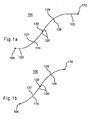
- Fig. 1a illustrates a longitudinal cross-sectional view of an embodiment of variable curvature stent limb 100 with a first straight region 102 and a second straight region 103.
- Fig. 1b illustrates a longitudinal cross-sectional view of a variable curvature stent 100 without the first straight region 102 and without the second straight region 103.
- the stent limb 100 has a first end 105 and a second end 110.
- the first straight region 102 begins at the first end 105 and is in this embodiment connected to a first variably curved region 115.
- the first curved region 115 may in turn be connected to an inner region 120.
- the inner region 120 may serve to connect the first curved region 115 with a second variably curved region 125.
- the inner region 120 may be straight or curved and may extend along a length between the first and second curved regions 115 and 125 or may constitute a point contact therebetween.
- the second curved region 125 may be connected to the second straight region 103, where the second straight region 103 terminates at the second end 110.
- first curved region 115 and the second curved region 125 may be concave. In another configuration, the first curved region 115 and the second curved region 125 each face opposite directions. The first curved region 115 and the second curved region 125 have a first radius of curvature 127 and a second radius of curvature 128, respectively. the second straight region 103, where the second straight region 103 terminates at the second end 110.
- first curved region 115 and the second curved region 125 may be concave. In another configuration, the first curved region 115 and the second curved region 125 each face opposite directions. The first curved region 115 and the second curved region 125 have a first radius of curvature 127 and a second radius of curvature 128, respectively.
- the first radius of curvature 127 and the second radius of curvature 128 are non-constant, such that the first radius of curvature 127 and the second radius of curvature 128 vary over the length of the curved regions 115 and 125, respectively.
- the first radius of curvature 127 and the second radius of curvature 128 may be the same.
- the first radius of curvature 127 and the second radius of curvature 128 may be different.
- the inner region 120 may include a midpoint 130, which is located equidistantfrom the first end 105 and the second end 110.
- the stent limb 100 may be symmetrical around the midpoint 130.
- the curved regions 115 and 125 may have identical length and curvature and the straight regions 105 and 125 may be of equal length.
- the midpoint 130 may represent a point of inversion.
- the various components of the limb 100 may be modified to affect the mechanical properties of the limb 100.
- the length of the straight regions 102 and 103 may be modified similarly.
- the length of the straight regions 102 and/or 103 may be modified in different manners.
- the straight regions 105 and 125 may not be present.
- the first curved region 115 begins at the first end 105 and the second curved region 125 terminates at the second end 110.
- the length and/or curvature of the curved regions 115 and 125 may be modified, similarly or individually.
- the length of the inner region 120 may be different.
- the inner region 120 may not be present so that the first curved region 115 and the second curved region 125 are connected directly to each other.
- the stent limb 100 may consist merely of the first curved region 115 and the second curved region 125, where the first curved region 115 and the second curved region 125 are connected at the midpoint 130.
- the material from which the stent limb 100 is constructed may also affect the mechanical properties of the stent limb 100.
- the stent limb 100 may be made of any deformable biocompatible material, such as polymeric materials, metals or ceramic materials.
- the stent limb 100 may be made of an elastic plastic metal, such as stainless steel.
- the stent limb 100 may be made of super elastic material, such as a shape memory alloy. Shape memory alloys may include nitinol.
- the stent limb 100 may be made from a combination of materials.
- the stent limb 100 may be formed by cutting the stent limb 100 from a sheet or a cannula. The cutting procedure may be achieved using a variety oftechniques, including a laser.
- the stent limb 100 may be formed by bending a wire or ribbon into the shape desired for stent limb 100.
- the stent limb 100 may be formed by determining the desired shape of the stent limb 100 computationally and building a form such that the ribbon or wire may be pressed into the desired shape.
- the ribbon or wire may be shaped by applying a load such that the ribbon or wire acquires the desired shape.
- a plurality of stent limbs 100 is be assembled to form a circular or tubular stent 195 as shown in Fig. 7 .
- a variety of methods may be employed to join the stent limb 100 to another stent limb 100. These methods include laser welding, fusion welding, soldering or even utilizing biocompatible epoxies.
- the entire stent 195 may be manufactured from a sheet or cannula, using a laser for example.
- the stent 195 may be formed by attaching a plurality of flat segments end to end such that the stent 195 is assembled in a fully compressed state.
- the stent 195 may be expanded over successive mandrels to achieve the appropriate size and then stress relieved. This process of expanding the stent 195 over successive mandrels may then provide the plurality of stent limbs 100 comprising the stent 195 with the desired shape.
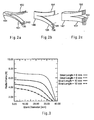
- Fig. 2a illustrates a longitudinal 3-dimensional view of a stent limb connection 145.
- Fig. 2b illustrates a longitudinal 3-dimensional view of a stent limb connection 146.
- a first stent limb 150 is attached to a second stent limb 151 via the stent limb connection 145.
- the stent limbs 150 and 151 a thickness 135 and a width 140.
- the thickness 135 is greater than the width 140.
- a first stent limb 154 may be attached to a second stent limb 155 via the stent limb connection 146. Furthermore, the stent limbs 154 and 155 have a width 141 and a thickness 136, where the width 141 is preferably greater than the thickness 136.
- a first stent limb 156 is attached to a second stent limb 157 via the stent limb connection 147. Furthermore, the stent limbs 156 and 157 have a width 142 and a thickness 137, where the width 142 is preferably the same as the thickness 137.
- the stent limbs are substantially rectangular or square in transverse cross-section, as shown for example in Figs. 2a to 2c .
- the limbs 154 and 155 When the stent limbs 154 and 155 are compressed together, the limbs 154 and 155 may be more likely to overlap than the stent limbs 150 and 151, since the thickness 136 is smaller than the width 141 in the stent limbs 154 and 155. However, the stent limbs 150 and 151 may be less likely to overlap upon compression, since increasing the thickness 135 in comparison to the width 140 may make it more difficult for the limbs 150 and 151 to pass over one another during compression. This in turn may reduce or prevent the occurrence of permanent deformation or out of plane buckling and/or twisting in a stent employing a plurality of limbs 150 and 151.
- the thickness 135 and the width 140 may be altered to affect the mechanical response or behavior of the stent limb 100. For example, it may be desirable to vary the thickness 135 and the width 140 over the length of the limb 100.
- Fig. 3 demonstrates how changes in the length of the variable curvature stent limb may influence the corresponding radial force curve.
- Radial force curves as discussed herein, provide a graphical comparison of the radial force (N) on the y-axis versus the stent diameter (mm) on the x-axis. Thus, the radial force curve indicates how much force is necessary to compress a stent to a given stent diameter.
- the radial force curves can also be interpreted as providing the amount of radial force that a stent will possess at a given stent diameter.
- the lenght of the stent limb is such as to provide radial force curve that does has a radial force plateau.
- a radial force plateau signifies a substantially constant radial force that exists over a range of stent diameters and appears as a nearly flat or horizontal region on the radial force curve.
- the radial force plateau may be broader, in which case it exists over a wider range of stent diameters, as compared to the radial force curve of another stent.
- a stent with a broad radial force plateau may be capable of being used for a wider range of diameters (i.e., diameters falling anywhere within the diameter range of the plateau).
- the radial force plateau may also vary in magnitude. For example, a higher or greater magnitude indicates that the corresponding stent has a plateau at a higher radial force, as compared to another stent. In fact, a higher magnitude radial force plateau may indicate that the corresponding stent may provide better sealing and support characteristics than a stent with a lower magnitude radial force plateau.
- Fig. 3 reveals that a decrease in the length of the stent limb 100 increases the magnitude of the radial force and causes a more pronounced plateau.
- Fig. 3 provides radial force curves for four different stent limbs 100, where each of the limbs varies in length.
- the radial force curves provided in Fig. 3 correspond to stent limb lengths of 6 mm, 8 mm,10 mm and 12 mm. Decreasing the length of the stent limb drives the stresses higher, such that stress induced martensite may occur. Thereby, resulting in a desirable flattening of the radial force curve.
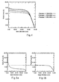
- Fig. 4 demonstrates how changes in the plateau stress of a super elastic material, such as a shape memory alloy, may alter the radial force curve.
- Fig. 4 provides radial force curves corresponding to three different stent limbs 100. Each of these stent limbs 100 are composed of nitinol, where the nitinol in each of the stent limbs 100 has a different plateau stress.
- the radial force curves correspond to stent limbs 100 with plateau stresses of 328 MPa, 358 MPa and 388 MPa. As the plateau stress of the stent limb 100 increases, the radial force plateaus also increase. This may be used to optimize the design of a stent depending on the radial force that is desired.
- Fig. 5a provides a radial force diagram for a stent employing an equal radius stent limb.
- Fig. 5b provides a radial force diagram for a stent employing a stent limb 100 possessing a variable curvature.
- a comparison of the two figures reveals that the equal radius stent limbs provide a radial force curve in which the plateau is narrower, since it extends over a smaller range of diameters ( Fig. 5a ) than the variable curvature stent limbs 100 ( Fig. 5b ).
- the equal radius stent limbs provide a radial force curve that is of a lower magnitude ( Fig.
- Fig. 5a a ) than the variable curvature stent limbs 100 ( Fig. 5b).
- Fig. 5a also reveals that at progressively smaller stent diameters, the equal radius stent limbs generate a steep increase in radial force, compared to the variable curvature stent limbs 100.
- variable curvature stent limbs 100 do not require a substantial increase in force to compress the stent diameter to stent diameters well below 5.0 mm. As a result, the variable curvature stent limbs 100 should result in lower interfacial forces between the stent 195 (see Fig.
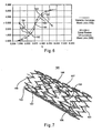
- Fig. 6 illustrates the shape of the variable curvature stent limb 100 compared to an equal radius of curvature stent limb 180.
- the equal radius of curvature stent limb 180 may have a first curved region 182 and a second curved region 183.
- the equal radii of curvature of the curved regions 182 and 183 are illustrated by a radius of curvature 184 and a radius of curvature 185, respectively.
- the stent limbs 100 and stent limb 180 also have a midpoint point 130, where the midpoint 130 serves as an inversion point between the two curved regions 115 and 125, as well as the curved regions 182 and 183.
- the curved regions 115 and 125 may be shallower or less concave than the curved regions 182 and 183.
- Fig. 7 illustrates a plurality of variable curvature stent limbs 100, where the plurality of stent limbs 100 are assembled in a pattern to create the stent 195.
- the stent limbs 100 are attached via a plurality of stent limb connections 196.
- the stent 195 may have a plurality of open cells 197, wherein the open cells 197 provide space between the stent limbs 100 to assist in the compression of the stent 195.
- Fig. 7 depicts the stent limbs 100 assembled in one pattern, the stent limbs 100 may also be assembled in a variety of other patterns as well.
- the shape of the stent limbs which could be described as an S-shape, provides a stent structure which can readily be compressed without creating excessive strain on the stent parts. In effect, upon compression, the limbs will be deflected into an more straight configuration, in some cases substantially exactly straight. The ability of the limbs to do this improves the compressibility of the stent 195, increasing its operable life and enabling it to be compressed more than prior art stents.
Landscapes
- Health & Medical Sciences (AREA)
- Engineering & Computer Science (AREA)
- Biomedical Technology (AREA)
- Life Sciences & Earth Sciences (AREA)
- Oral & Maxillofacial Surgery (AREA)
- Transplantation (AREA)
- Heart & Thoracic Surgery (AREA)
- Vascular Medicine (AREA)
- Cardiology (AREA)
- Animal Behavior & Ethology (AREA)
- General Health & Medical Sciences (AREA)
- Public Health (AREA)
- Veterinary Medicine (AREA)
- Media Introduction/Drainage Providing Device (AREA)
- Prostheses (AREA)
- Materials For Medical Uses (AREA)
Claims (16)
- Stentschenkel mit variabler Krümmung, der Folgendes umfasst: eine erste Region (115) mit variabler Krümmung, die an einer inneren Region (120) befestigt ist, wobei die erste Region (115) mit variabler Krümmung einen ersten Krümmungsradius aufweist, der sich über ihre Länge verändert, worin der erste Krümmungsradius nicht konstant ist; eine zweite Region (125) mit variabler Krümmung, die an einer inneren Region (120) befestigt ist, wobei die zweite Region mit variabler Krümmung einen zweiten Krümmungsradius aufweist, der sich über ihre Länge verändert, worin der zweite Krümmungsradius nicht konstant ist; worin die erste Region (115) mit variabler Krümmung und die zweite Region (125) mit variabler Krümmung in entgegengesetzte Richtungen weisen, dadurch gekennzeichnet, dass der Stentschenkel eine solche Länge aufweist, dass bei Kompression des Stentschenkels zu einer im Wesentlichen flachen Konfiguration ein radiales Kräfteplateau bereitgestellt wird.
- Stentschenkel nach Anspruch 1, worin der Stentschenkel eine Dicke (135) aufweist, die größer ist als die Breite (140).
- Stentschenkel nach Anspruch 1, worin die Dicke (135) und die Breite (140) des Stentschenkels im Wesentlichen gleich sind.
- Stentschenkel nach einem der vorhergehenden Ansprüche, der eine erste gerade Region (102), die an der ersten Region (115) mit variabler Krümmung befestigt ist, und eine zweite gerade Region (103) aufweist, die an der zweiten Region (125) mit variabler Krümmung befestigt ist.
- Stentschenkel nach Anspruch 4, worin die erste gerade Region (102) und die zweite gerade Region (103) im Wesentlichen dieselbe Länge aufweisen.
- Stentschenkel nach einem der vorhergehenden Ansprüche, worin die innere Region einen Mittelpunkt (130) aufweist, um die die erste Region (115) mit variabler Krümmung und die zweite Region (125) mit variabler Krümmung symmetrisch angeordnet sind.
- Stentschenkel nach einem der vorhergehenden Ansprüche, worin die erste Region (115) mit variabler Krümmung und die zweite Region (125) mit variabler Krümmung jeweils eine Krümmung aufweisen, die kleiner ist als eine imaginäre gleiche Radiuskurve, die sich von einem ersten Ende der Region mit variabler Krümmung bis zu dem oder einem Mittelpunkt des Stentschenkels erstreckt.
- Stentschenkel nach einem der vorhergehenden Ansprüche, worin der erste Krümmungsradius und der zweite Krümmungsradius gleich sind.
- Stentschenkel nach einem der vorhergehenden Ansprüche, worin die erste Region (115) mit variabler Krümmung und die zweite Region (125) mit variabler Krümmung aus einer Formgedächtnislegierung bestehen.
- Stentschenkel nach Anspruch 9, worin die Formgedächtnislegierung Nitinol ist.
- Stentschenkel nach einem der vorhergehenden Ansprüche, worin der Stentschenkel (100) zu einer im Wesentlichen flachen Konfiguration nachgiebig komprimiert werden kann.
- Stentschenkel nach einem der vorhergehenden Ansprüche, worin der Stentschenkel (100) einen im Wesentlichen rechteckigen oder quadratischen Querschnitt aufweist.
- Stent mit einer Vielzahl von Stentschenkeln (100) nach einem der vorhergehenden Ansprüche.
- Stent nach Anspruch 13, der eine Vielzahl von Stentschenkeln (100) aufweist, die aneinander befestigt sind, wobei die Stentschenkel zu im Wesentlichen flachen Formen komprimiert werden können.
- Stent nach Anspruch 13 oder 14, der eine Vielzahl von Ringen von miteinander verbundenen Stentschenkeln aufweist, wobei die Ringe hintereinander verbunden sind, um den Stent über eine Vielzahl von Stentschenkelverbindungen (196) zu bilden, die jeweils an einem Ende mit einem inneren Verbindungspunkt von zwei benachbarten Stentschenkeln eines der Stentringe und am anderen Ende mit einem äußeren Verbindungspunkt von zwei benachbarten Stentschenkeln eines anderen der Ringe verbunden sind.
- Medizinische Prothese mit einem Stent nach einem der Ansprüche 13 bis 15.
Applications Claiming Priority (2)
| Application Number | Priority Date | Filing Date | Title |
|---|---|---|---|
| US63481404P | 2004-12-09 | 2004-12-09 | |
| PCT/US2005/044600 WO2006063222A1 (en) | 2004-12-09 | 2005-12-08 | Variable curvature stent |
Publications (2)
| Publication Number | Publication Date |
|---|---|
| EP1827307A1 EP1827307A1 (de) | 2007-09-05 |
| EP1827307B1 true EP1827307B1 (de) | 2010-05-05 |
Family
ID=36035671
Family Applications (1)
| Application Number | Title | Priority Date | Filing Date |
|---|---|---|---|
| EP05853502A Active EP1827307B1 (de) | 2004-12-09 | 2005-12-08 | Stent mit variabler krümmung |
Country Status (8)
| Country | Link |
|---|---|
| US (1) | US7655033B2 (de) |
| EP (1) | EP1827307B1 (de) |
| JP (1) | JP4912321B2 (de) |
| AT (1) | ATE466557T1 (de) |
| AU (1) | AU2005313947B2 (de) |
| CA (1) | CA2579284C (de) |
| DE (1) | DE602005021151D1 (de) |
| WO (1) | WO2006063222A1 (de) |
Cited By (5)
| Publication number | Priority date | Publication date | Assignee | Title |
|---|---|---|---|---|
| US9545263B2 (en) | 2014-06-19 | 2017-01-17 | Limflow Gmbh | Devices and methods for treating lower extremity vasculature |
| US10543308B2 (en) | 2017-04-10 | 2020-01-28 | Limflow Gmbh | Methods for routing a guidewire from a first vessel and through a second vessel in lower extremity vasculature |
| US11116943B2 (en) | 2018-10-09 | 2021-09-14 | Limflow Gmbh | Methods for accessing pedal veins |
| US11446170B2 (en) | 2004-09-08 | 2022-09-20 | Limflow Gmbh | Minimally invasive surgical apparatus and methods |
| US11612397B2 (en) | 2019-11-01 | 2023-03-28 | Limflow Gmbh | Devices and methods for increasing blood perfusion to a distal extremity |
Families Citing this family (32)
| Publication number | Priority date | Publication date | Assignee | Title |
|---|---|---|---|---|
| DE202006021213U1 (de) | 2005-07-21 | 2013-11-08 | Covidien Lp | Vorrichtung zum Behandeln einer hohlen anatomischen Struktur |
| US20080195125A1 (en) * | 2007-02-12 | 2008-08-14 | Hoffman Grant T | Device for heart bypass surgery and anastomosis |
| US20090062839A1 (en) * | 2007-08-31 | 2009-03-05 | Cook Incorporated | Barbed stent vascular occlusion device |
| US8066757B2 (en) * | 2007-10-17 | 2011-11-29 | Mindframe, Inc. | Blood flow restoration and thrombus management methods |
| US8585713B2 (en) | 2007-10-17 | 2013-11-19 | Covidien Lp | Expandable tip assembly for thrombus management |
| US11337714B2 (en) | 2007-10-17 | 2022-05-24 | Covidien Lp | Restoring blood flow and clot removal during acute ischemic stroke |
| US8088140B2 (en) | 2008-05-19 | 2012-01-03 | Mindframe, Inc. | Blood flow restorative and embolus removal methods |
| US10123803B2 (en) | 2007-10-17 | 2018-11-13 | Covidien Lp | Methods of managing neurovascular obstructions |
| US8128677B2 (en) | 2007-12-12 | 2012-03-06 | Intact Vascular LLC | Device and method for tacking plaque to a blood vessel wall |
| US9180030B2 (en) | 2007-12-26 | 2015-11-10 | Cook Medical Technologies Llc | Low profile non-symmetrical stent |
| US9226813B2 (en) | 2007-12-26 | 2016-01-05 | Cook Medical Technologies Llc | Low profile non-symmetrical stent |
| US8574284B2 (en) | 2007-12-26 | 2013-11-05 | Cook Medical Technologies Llc | Low profile non-symmetrical bare alignment stents with graft |
| US9370437B2 (en) * | 2007-12-26 | 2016-06-21 | Cook Medical Technologies Llc | Stent having less invasive ends |
| GB2476451A (en) | 2009-11-19 | 2011-06-29 | Cook William Europ | Stent Graft |
| US8795345B2 (en) | 2009-07-08 | 2014-08-05 | Concentric Medical, Inc. | Vascular and bodily duct treatment devices and methods |
| US8357178B2 (en) * | 2009-07-08 | 2013-01-22 | Concentric Medical, Inc. | Vascular and bodily duct treatment devices and methods |
| US20110009941A1 (en) * | 2009-07-08 | 2011-01-13 | Concentric Medical, Inc. | Vascular and bodily duct treatment devices and methods |
| US8795317B2 (en) | 2009-07-08 | 2014-08-05 | Concentric Medical, Inc. | Embolic obstruction retrieval devices and methods |
| US9072537B2 (en) | 2009-07-08 | 2015-07-07 | Concentric Medical, Inc. | Vascular and bodily duct treatment devices and methods |
| US8357179B2 (en) | 2009-07-08 | 2013-01-22 | Concentric Medical, Inc. | Vascular and bodily duct treatment devices and methods |
| US8529596B2 (en) | 2009-07-08 | 2013-09-10 | Concentric Medical, Inc. | Vascular and bodily duct treatment devices and methods |
| US9757263B2 (en) | 2009-11-18 | 2017-09-12 | Cook Medical Technologies Llc | Stent graft and introducer assembly |
| US9259335B2 (en) | 2013-03-15 | 2016-02-16 | Covidien Lp | Stent |
| US9180031B2 (en) | 2013-03-15 | 2015-11-10 | Covidien Lp | Stent with varying radius between struts |
| US9375336B1 (en) | 2015-01-29 | 2016-06-28 | Intact Vascular, Inc. | Delivery device and method of delivery |
| US9433520B2 (en) | 2015-01-29 | 2016-09-06 | Intact Vascular, Inc. | Delivery device and method of delivery |
| US10993824B2 (en) | 2016-01-01 | 2021-05-04 | Intact Vascular, Inc. | Delivery device and method of delivery |
| US10258488B2 (en) | 2016-11-14 | 2019-04-16 | Covidien Lp | Stent |
| US10905572B2 (en) | 2016-11-14 | 2021-02-02 | Covidien Lp | Stent |
| US10449069B2 (en) | 2016-11-14 | 2019-10-22 | Covidien Lp | Stent |
| US11660218B2 (en) | 2017-07-26 | 2023-05-30 | Intact Vascular, Inc. | Delivery device and method of delivery |
| US11684498B2 (en) * | 2018-10-19 | 2023-06-27 | Inspire M.D Ltd. | Methods of using a self-adjusting stent assembly and kits including same |
Family Cites Families (30)
| Publication number | Priority date | Publication date | Assignee | Title |
|---|---|---|---|---|
| CA1246956A (en) * | 1983-10-14 | 1988-12-20 | James Jervis | Shape memory alloys |
| US4580568A (en) | 1984-10-01 | 1986-04-08 | Cook, Incorporated | Percutaneous endovascular stent and method for insertion thereof |
| US4886062A (en) | 1987-10-19 | 1989-12-12 | Medtronic, Inc. | Intravascular radially expandable stent and method of implant |
| US5133732A (en) | 1987-10-19 | 1992-07-28 | Medtronic, Inc. | Intravascular stent |
| US5019090A (en) | 1988-09-01 | 1991-05-28 | Corvita Corporation | Radially expandable endoprosthesis and the like |
| US5226913A (en) | 1988-09-01 | 1993-07-13 | Corvita Corporation | Method of making a radially expandable prosthesis |
| US5015253A (en) | 1989-06-15 | 1991-05-14 | Cordis Corporation | Non-woven endoprosthesis |
| CA2026604A1 (en) * | 1989-10-02 | 1991-04-03 | Rodney G. Wolff | Articulated stent |
| CA2380683C (en) * | 1991-10-28 | 2006-08-08 | Advanced Cardiovascular Systems, Inc. | Expandable stents and method for making same |
| US5630829A (en) * | 1994-12-09 | 1997-05-20 | Intervascular, Inc. | High hoop strength intraluminal stent |
| US6719782B1 (en) * | 1996-01-04 | 2004-04-13 | Endovascular Technologies, Inc. | Flat wire stent |
| ATE320771T1 (de) * | 1996-01-04 | 2006-04-15 | Timothy A M Dr Chuter | Flachdrahtstent |
| US6558415B2 (en) * | 1998-03-27 | 2003-05-06 | Intratherapeutics, Inc. | Stent |
| US6336937B1 (en) * | 1998-12-09 | 2002-01-08 | Gore Enterprise Holdings, Inc. | Multi-stage expandable stent-graft |
| US6273911B1 (en) * | 1999-04-22 | 2001-08-14 | Advanced Cardiovascular Systems, Inc. | Variable strength stent |
| US6409753B1 (en) * | 1999-10-26 | 2002-06-25 | Scimed Life Systems, Inc. | Flexible stent |
| US20020049490A1 (en) * | 2000-04-11 | 2002-04-25 | Pollock David T. | Single-piece endoprosthesis with high expansion ratios |
| AU5795401A (en) * | 2000-08-10 | 2002-02-14 | Cordis Corporation | Low profile radio-opaque stent with increased longitudinal flexibility and radial rigidity |
| US7037330B1 (en) * | 2000-10-16 | 2006-05-02 | Scimed Life Systems, Inc. | Neurovascular stent and method |
| AU2002233936A1 (en) * | 2000-11-07 | 2002-05-21 | Advanced Bio Prosthetic Surfaces, Ltd. | Endoluminal stent, self-fupporting endoluminal graft and methods of making same |
| EP1364676A4 (de) * | 2001-02-01 | 2007-10-31 | Kaneka Corp | Stent |
| US6673106B2 (en) | 2001-06-14 | 2004-01-06 | Cordis Neurovascular, Inc. | Intravascular stent device |
| US20030055485A1 (en) * | 2001-09-17 | 2003-03-20 | Intra Therapeutics, Inc. | Stent with offset cell geometry |
| US20030176914A1 (en) * | 2003-01-21 | 2003-09-18 | Rabkin Dmitry J. | Multi-segment modular stent and methods for manufacturing stents |
| US7803179B2 (en) * | 2002-05-30 | 2010-09-28 | Abbott Vascular Solutions Inc. | Intravascular stents |
| US7112055B1 (en) * | 2002-07-02 | 2006-09-26 | Endovascular Technologies, Inc. | Nitinol frame heating and setting mandrel |
| US7135038B1 (en) * | 2002-09-30 | 2006-11-14 | Advanced Cardiovascular Systems, Inc. | Drug eluting stent |
| AU2003275876A1 (en) * | 2002-10-31 | 2004-05-25 | Ecole De Technologie Superieure | Balloon deployable stent and method of using the same |
| US7169178B1 (en) * | 2002-11-12 | 2007-01-30 | Advanced Cardiovascular Systems, Inc. | Stent with drug coating |
| US6997946B2 (en) * | 2002-11-27 | 2006-02-14 | Boston Scientific Scimed, Inc. | Expandable stents |
-
2005
- 2005-12-08 US US11/297,913 patent/US7655033B2/en active Active
- 2005-12-08 JP JP2007545657A patent/JP4912321B2/ja active Active
- 2005-12-08 CA CA2579284A patent/CA2579284C/en active Active
- 2005-12-08 AU AU2005313947A patent/AU2005313947B2/en active Active
- 2005-12-08 DE DE602005021151T patent/DE602005021151D1/de active Active
- 2005-12-08 AT AT05853502T patent/ATE466557T1/de not_active IP Right Cessation
- 2005-12-08 WO PCT/US2005/044600 patent/WO2006063222A1/en active Application Filing
- 2005-12-08 EP EP05853502A patent/EP1827307B1/de active Active
Cited By (11)
| Publication number | Priority date | Publication date | Assignee | Title |
|---|---|---|---|---|
| US11446170B2 (en) | 2004-09-08 | 2022-09-20 | Limflow Gmbh | Minimally invasive surgical apparatus and methods |
| US9545263B2 (en) | 2014-06-19 | 2017-01-17 | Limflow Gmbh | Devices and methods for treating lower extremity vasculature |
| US10596356B2 (en) | 2014-06-19 | 2020-03-24 | Limflow Gmbh | Methods for placing a stent-graft to cover collateral vessels in lower extremity vasculature |
| US10543308B2 (en) | 2017-04-10 | 2020-01-28 | Limflow Gmbh | Methods for routing a guidewire from a first vessel and through a second vessel in lower extremity vasculature |
| US11826504B2 (en) | 2017-04-10 | 2023-11-28 | Limflow Gmbh | Methods for routing a guidewire from a first vessel and through a second vessel in lower extremity vasculature |
| US11116943B2 (en) | 2018-10-09 | 2021-09-14 | Limflow Gmbh | Methods for accessing pedal veins |
| US11129965B2 (en) | 2018-10-09 | 2021-09-28 | Limflow Gmbh | Devices and methods for catheter alignment |
| US11311700B2 (en) | 2018-10-09 | 2022-04-26 | Limflow Gmbh | Methods for accessing pedal veins |
| US11478614B2 (en) | 2018-10-09 | 2022-10-25 | Limflow Gmbh | Method for accessing pedal veins for deep vein arterialization |
| US11850379B2 (en) | 2018-10-09 | 2023-12-26 | Limflow Gmbh | Devices and methods for catheter alignment |
| US11612397B2 (en) | 2019-11-01 | 2023-03-28 | Limflow Gmbh | Devices and methods for increasing blood perfusion to a distal extremity |
Also Published As
| Publication number | Publication date |
|---|---|
| US7655033B2 (en) | 2010-02-02 |
| JP4912321B2 (ja) | 2012-04-11 |
| US20060161243A1 (en) | 2006-07-20 |
| CA2579284C (en) | 2013-06-25 |
| AU2005313947B2 (en) | 2010-09-23 |
| EP1827307A1 (de) | 2007-09-05 |
| AU2005313947A1 (en) | 2006-06-15 |
| ATE466557T1 (de) | 2010-05-15 |
| WO2006063222A1 (en) | 2006-06-15 |
| CA2579284A1 (en) | 2006-06-15 |
| JP2008522757A (ja) | 2008-07-03 |
| DE602005021151D1 (de) | 2010-06-17 |
Similar Documents
| Publication | Publication Date | Title |
|---|---|---|
| EP1827307B1 (de) | Stent mit variabler krümmung | |
| US6423090B1 (en) | Stent pattern with staged expansion | |
| JP5327971B2 (ja) | 変形可能な内腔支持器具及びその使用方法 | |
| EP0955950B1 (de) | Flachdrahtstent | |
| US6270524B1 (en) | Flexible, radially expansible luminal prostheses | |
| EP0961597B1 (de) | Bistabiler federaufbau für ein stent | |
| US5868780A (en) | Stents for supporting lumens in living tissue | |
| US8663311B2 (en) | Device comprising biodegradable bistable or multistable cells and methods of use | |
| JP4898990B2 (ja) | カニューレステント | |
| US20050015137A1 (en) | Flat wire stent | |
| US20070185560A1 (en) | Expandable stent | |
| EP1534184B1 (de) | Gerät für einen stent oder ein anderes medizinprodukt mit bistabiler federkonstruktion | |
| EP1895934B1 (de) | Intraluminale vorrichtung mit verbesserten konischen stützen | |
| JP4015659B2 (ja) | 関節のあるステント | |
| JP2002224224A (ja) | ステント | |
| JP2002224223A (ja) | ステント |
Legal Events
| Date | Code | Title | Description |
|---|---|---|---|
| PUAI | Public reference made under article 153(3) epc to a published international application that has entered the european phase |
Free format text: ORIGINAL CODE: 0009012 |
|
| AK | Designated contracting states |
Kind code of ref document: A1 Designated state(s): AT BE BG CH CY CZ DE DK EE ES FI FR GB GR HU IE IS IT LI LT LU LV MC NL PL PT RO SE SI SK TR |
|
| 17P | Request for examination filed |
Effective date: 20070302 |
|
| DAX | Request for extension of the european patent (deleted) | ||
| GRAP | Despatch of communication of intention to grant a patent |
Free format text: ORIGINAL CODE: EPIDOSNIGR1 |
|
| RIC1 | Information provided on ipc code assigned before grant |
Ipc: A61F 2/90 20060101AFI20091111BHEP |
|
| RAP1 | Party data changed (applicant data changed or rights of an application transferred) |
Owner name: MED INSTITUTE, INC. |
|
| GRAS | Grant fee paid |
Free format text: ORIGINAL CODE: EPIDOSNIGR3 |
|
| GRAA | (expected) grant |
Free format text: ORIGINAL CODE: 0009210 |
|
| AK | Designated contracting states |
Kind code of ref document: B1 Designated state(s): AT BE BG CH CY CZ DE DK EE ES FI FR GB GR HU IE IS IT LI LT LU LV MC NL PL PT RO SE SI SK TR |
|
| REG | Reference to a national code |
Ref country code: GB Ref legal event code: FG4D |
|
| REG | Reference to a national code |
Ref country code: CH Ref legal event code: EP |
|
| REG | Reference to a national code |
Ref country code: IE Ref legal event code: FG4D |
|
| REF | Corresponds to: |
Ref document number: 602005021151 Country of ref document: DE Date of ref document: 20100617 Kind code of ref document: P |
|
| REG | Reference to a national code |
Ref country code: NL Ref legal event code: VDEP Effective date: 20100505 |
|
| LTIE | Lt: invalidation of european patent or patent extension |
Effective date: 20100505 |
|
| PG25 | Lapsed in a contracting state [announced via postgrant information from national office to epo] |
Ref country code: LT Free format text: LAPSE BECAUSE OF FAILURE TO SUBMIT A TRANSLATION OF THE DESCRIPTION OR TO PAY THE FEE WITHIN THE PRESCRIBED TIME-LIMIT Effective date: 20100505 Ref country code: ES Free format text: LAPSE BECAUSE OF FAILURE TO SUBMIT A TRANSLATION OF THE DESCRIPTION OR TO PAY THE FEE WITHIN THE PRESCRIBED TIME-LIMIT Effective date: 20100816 Ref country code: SE Free format text: LAPSE BECAUSE OF FAILURE TO SUBMIT A TRANSLATION OF THE DESCRIPTION OR TO PAY THE FEE WITHIN THE PRESCRIBED TIME-LIMIT Effective date: 20100505 Ref country code: NL Free format text: LAPSE BECAUSE OF FAILURE TO SUBMIT A TRANSLATION OF THE DESCRIPTION OR TO PAY THE FEE WITHIN THE PRESCRIBED TIME-LIMIT Effective date: 20100505 |
|
| PG25 | Lapsed in a contracting state [announced via postgrant information from national office to epo] |
Ref country code: IS Free format text: LAPSE BECAUSE OF FAILURE TO SUBMIT A TRANSLATION OF THE DESCRIPTION OR TO PAY THE FEE WITHIN THE PRESCRIBED TIME-LIMIT Effective date: 20100905 Ref country code: AT Free format text: LAPSE BECAUSE OF FAILURE TO SUBMIT A TRANSLATION OF THE DESCRIPTION OR TO PAY THE FEE WITHIN THE PRESCRIBED TIME-LIMIT Effective date: 20100505 Ref country code: LV Free format text: LAPSE BECAUSE OF FAILURE TO SUBMIT A TRANSLATION OF THE DESCRIPTION OR TO PAY THE FEE WITHIN THE PRESCRIBED TIME-LIMIT Effective date: 20100505 Ref country code: SI Free format text: LAPSE BECAUSE OF FAILURE TO SUBMIT A TRANSLATION OF THE DESCRIPTION OR TO PAY THE FEE WITHIN THE PRESCRIBED TIME-LIMIT Effective date: 20100505 Ref country code: FI Free format text: LAPSE BECAUSE OF FAILURE TO SUBMIT A TRANSLATION OF THE DESCRIPTION OR TO PAY THE FEE WITHIN THE PRESCRIBED TIME-LIMIT Effective date: 20100505 |
|
| PG25 | Lapsed in a contracting state [announced via postgrant information from national office to epo] |
Ref country code: GR Free format text: LAPSE BECAUSE OF FAILURE TO SUBMIT A TRANSLATION OF THE DESCRIPTION OR TO PAY THE FEE WITHIN THE PRESCRIBED TIME-LIMIT Effective date: 20100806 Ref country code: PL Free format text: LAPSE BECAUSE OF FAILURE TO SUBMIT A TRANSLATION OF THE DESCRIPTION OR TO PAY THE FEE WITHIN THE PRESCRIBED TIME-LIMIT Effective date: 20100505 Ref country code: CY Free format text: LAPSE BECAUSE OF FAILURE TO SUBMIT A TRANSLATION OF THE DESCRIPTION OR TO PAY THE FEE WITHIN THE PRESCRIBED TIME-LIMIT Effective date: 20100512 |
|
| PG25 | Lapsed in a contracting state [announced via postgrant information from national office to epo] |
Ref country code: EE Free format text: LAPSE BECAUSE OF FAILURE TO SUBMIT A TRANSLATION OF THE DESCRIPTION OR TO PAY THE FEE WITHIN THE PRESCRIBED TIME-LIMIT Effective date: 20100505 Ref country code: DK Free format text: LAPSE BECAUSE OF FAILURE TO SUBMIT A TRANSLATION OF THE DESCRIPTION OR TO PAY THE FEE WITHIN THE PRESCRIBED TIME-LIMIT Effective date: 20100505 Ref country code: PT Free format text: LAPSE BECAUSE OF FAILURE TO SUBMIT A TRANSLATION OF THE DESCRIPTION OR TO PAY THE FEE WITHIN THE PRESCRIBED TIME-LIMIT Effective date: 20100906 |
|
| PLBI | Opposition filed |
Free format text: ORIGINAL CODE: 0009260 |
|
| PG25 | Lapsed in a contracting state [announced via postgrant information from national office to epo] |
Ref country code: CZ Free format text: LAPSE BECAUSE OF FAILURE TO SUBMIT A TRANSLATION OF THE DESCRIPTION OR TO PAY THE FEE WITHIN THE PRESCRIBED TIME-LIMIT Effective date: 20100505 Ref country code: RO Free format text: LAPSE BECAUSE OF FAILURE TO SUBMIT A TRANSLATION OF THE DESCRIPTION OR TO PAY THE FEE WITHIN THE PRESCRIBED TIME-LIMIT Effective date: 20100505 Ref country code: BE Free format text: LAPSE BECAUSE OF FAILURE TO SUBMIT A TRANSLATION OF THE DESCRIPTION OR TO PAY THE FEE WITHIN THE PRESCRIBED TIME-LIMIT Effective date: 20100505 Ref country code: SK Free format text: LAPSE BECAUSE OF FAILURE TO SUBMIT A TRANSLATION OF THE DESCRIPTION OR TO PAY THE FEE WITHIN THE PRESCRIBED TIME-LIMIT Effective date: 20100505 |
|
| PLAX | Notice of opposition and request to file observation + time limit sent |
Free format text: ORIGINAL CODE: EPIDOSNOBS2 |
|
| 26 | Opposition filed |
Opponent name: MEDINOL LTD. Effective date: 20110207 |
|
| PG25 | Lapsed in a contracting state [announced via postgrant information from national office to epo] |
Ref country code: IT Free format text: LAPSE BECAUSE OF FAILURE TO SUBMIT A TRANSLATION OF THE DESCRIPTION OR TO PAY THE FEE WITHIN THE PRESCRIBED TIME-LIMIT Effective date: 20100505 |
|
| REG | Reference to a national code |
Ref country code: DE Ref legal event code: R026 Ref document number: 602005021151 Country of ref document: DE Effective date: 20110207 |
|
| PLAF | Information modified related to communication of a notice of opposition and request to file observations + time limit |
Free format text: ORIGINAL CODE: EPIDOSCOBS2 |
|
| PG25 | Lapsed in a contracting state [announced via postgrant information from national office to epo] |
Ref country code: MC Free format text: LAPSE BECAUSE OF NON-PAYMENT OF DUE FEES Effective date: 20101231 |
|
| PLBB | Reply of patent proprietor to notice(s) of opposition received |
Free format text: ORIGINAL CODE: EPIDOSNOBS3 |
|
| REG | Reference to a national code |
Ref country code: CH Ref legal event code: PL |
|
| REG | Reference to a national code |
Ref country code: GB Ref legal event code: 732E Free format text: REGISTERED BETWEEN 20110804 AND 20110810 |
|
| REG | Reference to a national code |
Ref country code: FR Ref legal event code: ST Effective date: 20110831 |
|
| PG25 | Lapsed in a contracting state [announced via postgrant information from national office to epo] |
Ref country code: CH Free format text: LAPSE BECAUSE OF NON-PAYMENT OF DUE FEES Effective date: 20101231 Ref country code: FR Free format text: LAPSE BECAUSE OF NON-PAYMENT OF DUE FEES Effective date: 20110103 Ref country code: LI Free format text: LAPSE BECAUSE OF NON-PAYMENT OF DUE FEES Effective date: 20101231 |
|
| RAP2 | Party data changed (patent owner data changed or rights of a patent transferred) |
Owner name: COOK MEDICAL TECHNOLOGIES LLC |
|
| PG25 | Lapsed in a contracting state [announced via postgrant information from national office to epo] |
Ref country code: HU Free format text: LAPSE BECAUSE OF FAILURE TO SUBMIT A TRANSLATION OF THE DESCRIPTION OR TO PAY THE FEE WITHIN THE PRESCRIBED TIME-LIMIT Effective date: 20101106 Ref country code: LU Free format text: LAPSE BECAUSE OF NON-PAYMENT OF DUE FEES Effective date: 20101208 Ref country code: BG Free format text: LAPSE BECAUSE OF FAILURE TO SUBMIT A TRANSLATION OF THE DESCRIPTION OR TO PAY THE FEE WITHIN THE PRESCRIBED TIME-LIMIT Effective date: 20100505 |
|
| PG25 | Lapsed in a contracting state [announced via postgrant information from national office to epo] |
Ref country code: TR Free format text: LAPSE BECAUSE OF FAILURE TO SUBMIT A TRANSLATION OF THE DESCRIPTION OR TO PAY THE FEE WITHIN THE PRESCRIBED TIME-LIMIT Effective date: 20100505 |
|
| PLAB | Opposition data, opponent's data or that of the opponent's representative modified |
Free format text: ORIGINAL CODE: 0009299OPPO |
|
| R26 | Opposition filed (corrected) |
Opponent name: MEDINOL LTD. Effective date: 20110207 |
|
| PG25 | Lapsed in a contracting state [announced via postgrant information from national office to epo] |
Ref country code: BG Free format text: LAPSE BECAUSE OF FAILURE TO SUBMIT A TRANSLATION OF THE DESCRIPTION OR TO PAY THE FEE WITHIN THE PRESCRIBED TIME-LIMIT Effective date: 20100805 |
|
| REG | Reference to a national code |
Ref country code: DE Ref legal event code: R100 Ref document number: 602005021151 Country of ref document: DE |
|
| PLCK | Communication despatched that opposition was rejected |
Free format text: ORIGINAL CODE: EPIDOSNREJ1 |
|
| PLBN | Opposition rejected |
Free format text: ORIGINAL CODE: 0009273 |
|
| STAA | Information on the status of an ep patent application or granted ep patent |
Free format text: STATUS: OPPOSITION REJECTED |
|
| 27O | Opposition rejected |
Effective date: 20140618 |
|
| REG | Reference to a national code |
Ref country code: DE Ref legal event code: R100 Ref document number: 602005021151 Country of ref document: DE Effective date: 20140618 |
|
| P01 | Opt-out of the competence of the unified patent court (upc) registered |
Effective date: 20230602 |
|
| PGFP | Annual fee paid to national office [announced via postgrant information from national office to epo] |
Ref country code: GB Payment date: 20231108 Year of fee payment: 19 |
|
| PGFP | Annual fee paid to national office [announced via postgrant information from national office to epo] |
Ref country code: IE Payment date: 20231128 Year of fee payment: 19 Ref country code: DE Payment date: 20231108 Year of fee payment: 19 |