EP1826453A1 - Damping force adjusting apparatus of front fork - Google Patents
Damping force adjusting apparatus of front fork Download PDFInfo
- Publication number
- EP1826453A1 EP1826453A1 EP06019598A EP06019598A EP1826453A1 EP 1826453 A1 EP1826453 A1 EP 1826453A1 EP 06019598 A EP06019598 A EP 06019598A EP 06019598 A EP06019598 A EP 06019598A EP 1826453 A1 EP1826453 A1 EP 1826453A1
- Authority
- EP
- European Patent Office
- Prior art keywords
- push rod
- adjusting portion
- piston rod
- axial direction
- front fork
- Prior art date
- Legal status (The legal status is an assumption and is not a legal conclusion. Google has not performed a legal analysis and makes no representation as to the accuracy of the status listed.)
- Granted
Links
Images




Classifications
-
- F—MECHANICAL ENGINEERING; LIGHTING; HEATING; WEAPONS; BLASTING
- F16—ENGINEERING ELEMENTS AND UNITS; GENERAL MEASURES FOR PRODUCING AND MAINTAINING EFFECTIVE FUNCTIONING OF MACHINES OR INSTALLATIONS; THERMAL INSULATION IN GENERAL
- F16F—SPRINGS; SHOCK-ABSORBERS; MEANS FOR DAMPING VIBRATION
- F16F9/00—Springs, vibration-dampers, shock-absorbers, or similarly-constructed movement-dampers using a fluid or the equivalent as damping medium
- F16F9/32—Details
- F16F9/44—Means on or in the damper for manual or non-automatic adjustment; such means combined with temperature correction
-
- B—PERFORMING OPERATIONS; TRANSPORTING
- B62—LAND VEHICLES FOR TRAVELLING OTHERWISE THAN ON RAILS
- B62K—CYCLES; CYCLE FRAMES; CYCLE STEERING DEVICES; RIDER-OPERATED TERMINAL CONTROLS SPECIALLY ADAPTED FOR CYCLES; CYCLE AXLE SUSPENSIONS; CYCLE SIDECARS, FORECARS, OR THE LIKE
- B62K25/00—Axle suspensions
- B62K25/04—Axle suspensions for mounting axles resiliently on cycle frame or fork
- B62K25/06—Axle suspensions for mounting axles resiliently on cycle frame or fork with telescopic fork, e.g. including auxiliary rocking arms
- B62K25/08—Axle suspensions for mounting axles resiliently on cycle frame or fork with telescopic fork, e.g. including auxiliary rocking arms for front wheel
-
- F—MECHANICAL ENGINEERING; LIGHTING; HEATING; WEAPONS; BLASTING
- F16—ENGINEERING ELEMENTS AND UNITS; GENERAL MEASURES FOR PRODUCING AND MAINTAINING EFFECTIVE FUNCTIONING OF MACHINES OR INSTALLATIONS; THERMAL INSULATION IN GENERAL
- F16F—SPRINGS; SHOCK-ABSORBERS; MEANS FOR DAMPING VIBRATION
- F16F9/00—Springs, vibration-dampers, shock-absorbers, or similarly-constructed movement-dampers using a fluid or the equivalent as damping medium
- F16F9/32—Details
- F16F9/58—Stroke limiting stops, e.g. arranged on the piston rod outside the cylinder
- F16F9/585—Stroke limiting stops, e.g. arranged on the piston rod outside the cylinder within the cylinder, in contact with working fluid
Definitions
- the present invention relates to a damping force adjusting apparatus of a front fork.
- Japanese Utility Model Registration No. 2581704 (patent document 1) describes a hydraulic buffer.
- a piston rod is movably inserted into a cylinder through a piston, the piston defines the cylinder into a rod-side oil chamber and a piston-side oil chamber. These two oil chambers are brought into communication with each other through an expansion-side port and a compression-side port formed in the piston.
- An expansion-side leaf valve and a compression-side leaf valve are provided in outlets of the expansion-side port and the compression-side port such that the leaf valves can open and close.
- the piston rod is provided with an expansion-side bypass and a compression-side bypass which bring the two oil chambers into communication with each other.
- the expansion-side bypass and the compression-side bypass are opened such that they are oriented toward back surfaces of the expansion-side leaf valve and the compression-side leaf valve rather than their pressure-receiving surfaces.
- Check valves are provided at outlet ends of the expansion-side bypass and the compression-side bypass such that the check valves can open and close.
- An adjuster rod which can move in a rotational direction and an axial direction is inserted into the piston rod.
- the adjuster rod is provided at its tip end with a first valve body which opens and closes the expansion-side bypass as the adjuster rod vertically moves, and the adjuster rod is provided with a second valve body which opens and closes the compression-side bypass as the adjuster rod rotates.
- the damping force adjusting apparatus of the patent document 1 has the following problems.
- the present invention relates to a damping force adjusting apparatus of a front fork in which an inner tube on an axle side is slidably inserted into an outer tube on a vehicle body side, the inner tube is provided at its inner periphery with a division wall member, a working oil chamber is defined in a lower portion of the division wall member, and an oil reservoir chamber is defined in an upper portion of the division wall member, a hollow piston rod mounted on the outer tube side is inserted into the working oil chamber through the division wall member, the piston rod is provided at its tip end with a piston which slides in the working oil chamber, the working oil chamber of the inner tube is divided by a piston into a piston rod-side oil chamber and a piston-side oil chamber, the two oil chambers can be in communication with a compression-side flow path and an expansion-side flow path formed in the piston, outlets of the two flow paths are respectively provided with a compression-side damping valve and an expansion-side damping valve, a hollow portion of the piston rod is provided with a bypass passage which brings the piston
- the hollow portion of the piston rod is provided with a push rod having a noncircular cross section, the push rod can move in the rotational direction and the axial direction.
- a first adjusting portion which moves the push rod in the rotational direction and a second adjusting portion which moves the push rod in the axial direction are coaxially disposed on an extension of the push rod at an upper portion of the front fork.
- the needle valve which is slidably inserted into the noncircular cross section of the push rod is threadedly engaged with the hollow portion of the piston rod.
- a spring which collides against the push rod in the axial direction biases the compression-side damping valve in its closing direction.
- a front fork 10 is an inverted-type front fork in which an outer tube 11 is disposed on the side of a vehicle body and an inner tube 12 is disposed on the side of a wheel.
- the inner tube 12 is slidably inserted into the outer tube 11 through a guide bush 11A fixed to an inner periphery of a lower end opening of the outer tube 11 and a guide bush 12A fixed to an outer periphery of an upper end opening of the inner tube 12.
- Reference numeral 11B represents an oil seal
- reference numeral 11C represents a dust seal.
- a cap 13 is liquid-tightly threadedly engaged with the upper end opening of the outer tube 11, and the outer tube 11 is provided at its outer periphery with vehicle body-side mounting members 14A and 14B.
- An axle bracket 15 is liquid-tightly inserted into and engaged with the lower end opening of the inner tube 12, thereby forming a bottom of the inner tube 12, and the axle bracket 15 is provided with an axle mounting hole 16.
- the front fork 10 defines an annular oil chamber 17 which is defined by an inner periphery of the outer tube 11, the outer periphery of the inner tube 12 and the two guide bushes 11A and 12A.
- the front fork 10 is liquid-tightly provided with a division wall member 19 through an O-ring on an inner periphery of the upper end of the inner tube 12.
- the division wall member 19 defines an working oil chamber 21 in a lower portion lower than the rod guide portion 19A, and defines an oil reservoir chamber 22 in an upper portion.
- a lower region in the oil reservoir chamber 22 is an oil chamber 22A and an upper region in the oil reservoir chamber 22 is an air chamber 22B.
- the front fork 10 slidably inserts a piston rod 23 mounted on the outer tube 11 into the rod guide portion 19A of the division wall member 19. More specifically, a hollow piston rod 23 is threadedly engaged with a mounting collar 24 which is threadedly engaged with a lower end of a center portion of the cap 13 and is fixed by the lock nut 24A.
- the front fork 10 fixes a piston 26 which slides on an inner periphery of the inner tube 12 to a piston bolt 25 which is threadedly engaged with a tip end of the piston rod 23 inserted into the inner tube 12 from the rod guide portion 19A of the division wall member 19, and divides the working oil chamber 21 into a piston rod-side oil chamber 21A in which the piston rod 23 is accommodated and a piston-side oil chamber 21B in which the piston rod 23 is not accommodated.
- the piston 26 is fixed by a nut 27.
- the front fork 10 always brings the annular oil chamber 17 into communication with the piston rod-side oil chamber 21A through an oil hole 28 formed in the inner tube 12.
- the front fork 10 brings an upper spring receiver 31 into abutment against a lower end surface of the piston 26 facing the piston-side oil chamber 21B, disposes a lower spring receiver 32 on a bottom of the inner tube 12 formed by the axle bracket 15, and interposes a suspension spring 33 between an upper spring receiver 31 and a lower spring receiver 32.
- the front fork 10 absorbs an impact force received from a road surface when the vehicle runs by expansion and contraction vibration of a suspension spring 33.
- the front fork 10 threadedly engages an adjusting nut 35 with an adjusting bolt 34 provided such as to face outside at a position (on the side of the axle mounting hole 16) deviated from the axle mounting hole 16 of the axle bracket 15 constituting a bottom of the inner tube 12, prevents the adjusting nut 35 from rotating by a detent washer 36 provided in the inner tube 12, disposes a slider 37 on a lower portion of the detent washer 36 in the bottom of the inner tube, slides and guides an outer surface of the adjusting nut 35 by the slider 37, and supports a back surface of the lower spring receiver 32 through a washer 38 on a tip end of the adjusting nut 35.
- the adjusting bolt 34 By turning and operating the adjusting bolt 34 from outside, the adjusting nut 35 which is prevented from rotating by the detent washer 36 is moved straightly, and the lower spring receiver 32 supported by a back surface of the adjusting nut 35 is vertically moved. Since the adjusting bolt 34 is provided such as to face outside at the position deviated from the axle mounting hole 16 of the inner tube 12, a spring load of the suspension spring 33 can be adjusted without detaching the front fork 10 from the axle.
- the piston 26 of the front fork 10 includes a damping force generating apparatus 40 (FIG. 2).
- the damping force generating apparatus 40 includes a compression-side flow path 41 and an expansion-side flow path 42 (now shown).
- the compression-side flow path 41 is opened and closed by a compression-side disc valve 41A (compression-side damping valve) which is backed up by the valve stopper 41B.
- the expansion-side flow path 42 is opened and closed by an expansion-side disc valve 42A (expansion-side damping valve) which is backed up by the valve stopper 42B.
- the valve stopper 41B, the valve 41A, the piston 26, the valve 42A and the valve stopper 42B constitute a valve assembly inserted into the piston bolt 25, and are sandwiched and fixed by the nut 27 threadedly engaged with the piston bolt 25.
- the damping force generating apparatus 40 is provided at a center of the cap 13 with a damping force adjusting apparatus 40A, inserts a needle valve 85 of the damping force adjusting apparatus 40A into a hollow of the piston rod 23, and adjusts the opening degree of a bypass passage 45 provided in the piston rod 23 by a vertical movement of the needle valve 85.
- the bypass passage 45 bypasses the piston 26, and brings the piston rod-side oil chamber 21A and the piston-side oil chamber 21B into communication with each other.
- the damping force generating apparatus 40 generates a compression-side damping force by a passage resistance of the bypass passage 45 whose opening degree is adjusted by the needle valve 85 during a compression-side stroke, the compression-side disc valve 41A is bent and deformed in intermediate speed and high speed regions, and compression-side damping force is generated.
- expansion-side stroke in a low speed region, expansion-side damping force is generated by a passage resistance of the bypass passage 45 whose opening degree is adjusted by the needle valve 85, the expansion-side disc valve 42A is bent and deformed in the intermediate speed and high speed regions, and the expansion-side damping force is generated.
- the compression-side damping force and the expansion-side damping force damp the expansion and contraction vibration of the suspension spring 33.
- the front fork 10 fixes, to a lower end surface of the cap 13, a stopper rubber 13A and a stopper plate 13B against which an upper end of the division wall member 19 provided on the inner tube 12.
- the stopper rubber 13A restricts the most compressing stroke.
- a spring sheet 51 is swaged and fixed to a lower end surface of the division wall member 19 on the side of an upper end of the inner tube 12 facing the piston rod-side oil chamber 21A.
- a spring sheet 52 is retained to a stopper ring 52A provided on the piston rod 23.
- the front fork 10 interposes a rebound spring 53 between the spring sheet 51 and the spring sheet 52. When the front fork 10 is most expanded, the division wall member 19 presses the rebound spring 53 between the division wall member 19 and the spring sheet 52, thereby restricting the most expanding stroke.
- a cross-sectional area S1 of the annular oil chamber 17 comprising an annular gap between the outer tube 11 and the inner tube 12 is set greater than a cross-sectional area (area surrounded by outer diameter) S2 of the piston rod 23 (S1>S2 including S1 ⁇ 2).
- the rod guide portion 19A of the division wall member 19 is provided with a check valve 60.
- the check valve 60 permits oil to flow into the piston rod-side oil chamber 21A from the oil reservoir chamber 22 during the compression-side stroke, and the check valve 60 prevents oil from flowing into the oil reservoir chamber 22 from the piston rod-side oil chamber 21A during the expansion-side stroke.
- a valve chamber 61 is provided in an inner periphery of the rod guide portion 19A of the division wall member 19.
- the check valve 60 is accommodated between a step 61A on an upper end side of the valve chamber 61 and a back up spring 62 on the spring sheet 51 provided on the lower end side of the valve chamber 61.
- the check valve 60 is shorter than a gap between the step 61A and the spring sheet 51, and a lateral groove is formed in the lower end surface.
- the check valve 60 can slide on an inner periphery of the valve chamber 61 provided on the rod guide portion 19A of the division wall member 19 and can be displaced vertically.
- a flow path is formed between the outer periphery of the check valve 60 and the inner periphery of the valve chamber 61 provided in the rod guide portion 19A of the division wall member 19, and oil flows from the oil reservoir chamber 22 to the piston rod-side oil chamber 21A through this flow path.
- a bush 63 is press-fitted into an inner periphery of the check valve 60. The bush 63 slidably supports the piston rod 23.
- the check valve 60 moves together with the piston rod 23 which enters the inner tube 12 and moves downward, and collides against the spring sheet 51, forms a gap between the check valve 60 and the step 61A, so that oil in the oil reservoir chamber 22 can pass through a gap between the step 61A through an outer periphery of the lateral groove from the lateral groove, and the oil can flow into the piston rod-side oil chamber 21A.
- the check valve 60 moves together with the piston rod 23 which retreats from the inner tube 12 and moves upward, collides against the step 61A, closes the gap between the step 61A, and the check valve 60 prevents oil in the piston rod-side oil chamber 21A from being discharged into the oil reservoir chamber 22 through a path opposite from that of the compression-side stroke.
- the rod guide portion 19A of the division wall member 19 does not have an oil seal around the piston rod 23.
- the bush 63 which is press-fitted into the inner periphery of the check valve 60 constitutes a fine flow path (orifice) 64 which brings the piston rod-side oil chamber 21A and the oil reservoir chamber 22 into communication with each other by a fine gap (or fine gap formed between the check valve 60 and the step 61A) formed around the piston rod 23.
- the fine flow path 64 may be formed in the rod guide portion 19A of the division wall member 19.
- the piston rod-side oil chamber 21A and the oil reservoir chamber 22 are in communication with each other through the fine flow path 64.
- the front fork 10 is operated in the following manner.
- an expansion-side damping force is generated in the low speed region by a passage resistance of the bypass passage 45 whose opening degree is adjusted by the needle valve 85, and in the intermediate speed and high speed regions, the expansion-side disc valve 42A is bent and deformed and an expansion-side damping force is generated.
- the expansion-side damping force is also generated due to the passage resistance of the fine flow path 64.
- the damping force adjusting apparatus 40A will be explained.
- one push rod 70 is provided on a hollow portion of the piston rod 23.
- the push rod 70 has a noncircular cross section (D-shaped cross section in this embodiment).
- the push rod 70 can move in the rotational direction and the axial direction.
- a first adjusting portion 80 which moves the push rod 70 in the rotational direction and a second adjusting portion 90 which moves the push rod 70 in the axial direction are coaxially disposed on an extension of the push rod 70 at an upper portion of the front fork 10.
- the needle valve 85 is slidably inserted into the noncircular cross section of the push rod 70.
- the damping force adjusting apparatus 40A threadedly engages the needle valve 85 with the hollow portion of the piston rod 23, the needle valve 85 is threadedly moved by the rotation of the first adjusting portion 80, the opening degree of the bypass passage 45 is adjusted by the needle valve 85, and the damping force can be adjusted by the passage resistance of the bypass passage 45.
- the damping force adjusting apparatus 40A biases the compression-side disc valve 41A in its closing direction by a spring 95 which collides against the push rod 70 in the axial direction, the compression-side disc valve 41A is bent and deformed and the compression-side damping force can be adjusted. Structures of the first adjusting portion 80 and the second adjusting portion 90, a damping force adjusting structure using the needle valve 85 and a damping force adjusting structure using the spring 95 will be explained.
- a cap 13 constitutes a cap assembly shown in FIGS. 5.
- the cap 13 is liquid-tightly threadedly engaged with an upper end opening of the outer tube 11 through an O-ring 13C.
- the mounting collar 24 is threadedly engaged with a lower end opening of the cap 13, and an upper end of the piston rod 23 shown in FIG. 6 is threadedly engaged with the mounting collar 24, and is fixed by the lock nut 24A.
- the first adjusting portion 80 is liquid-tightly inserted from a lower end opening of a center hole of the cap 13 through an O-ring 81.
- the first adjusting portion 80 is engaged with an intermediate step of the cap 13 in the axial direction and is prevented from being pulled out upward, the first adjusting portion 80 axially collides against the flat washer 82 placed on an upper end surface of the mounting collar 24 which is threadedly engaged with a lower end opening of the cap 13, the first adjusting portion 80 is prevented from being pulled out downward and as a result, the first adjusting portion 80 is rotatably provided on the cap 13 using the operating surface 80A on the upper end outer periphery.
- the lower end surface of the first adjusting portion 80 which collides against the flat washer 82 includes the lateral groove 80B as shown in FIGS. 7. Both side projections 83A of an engaging piece 83 shown in FIG. 8 are engaged with the lateral groove 80B in the rotational direction almost without play.
- the second adjusting portion 90 is liquid-tightly inserted from the lower end opening of the center hole of the first adjusting portion 80 through an O-ring 91.
- the second adjusting portion 90 engages with the intermediate step of the first adjusting portion 80 in the axial direction and is prevented from being pulled out upward.
- the lower end surface of the second adjusting portion 90 collides against an upper end surface of the push rod 70 without gap in the axial direction.
- the push rod 70 penetrates a noncircular hole 83B of the engaging piece 83 which is engaged with a side of the first adjusting portion 80.
- the push rod 70 is biased upward by a spring force of the later-described spring 95, and an upper end surface of the push rod 70 always collides against the lower end surface of the second adjusting portion 90.
- the second adjusting portion 90 is threadedly moved with respect to the first adjusting portion 80 using an operating groove 90A in an upper end surface of the second adjusting portion 90 shown in FIG. 10 and the push rod 70 can be moved in the axial direction.
- the inner base 84 shown in FIG. 11 is inserted into the lower end of the hollow portion of the piston rod 23, and the lower end surface of the piston rod 23 and the inner diameter step of the piston bolt 25 sandwich and fix the lower end flange 84A of the inner base 84.
- the inner base 84 may be press-fitted into the hollow portion of the piston rod 23.
- the screw portion 85B of the intermediate portion of the needle valve 85 shown in FIG. 12 is threadedly engaged with the inner periphery of the inner base 84 fixed to the piston rod 23 in this manner.
- a noncircular cross sectional portion 85A having a noncircular cross section (D-shaped cross section in this embodiment) of the upper end of the needle valve 85 is inserted into the noncircular cross section of the lower end of the push rod 70 inserted into the hollow portion of the piston rod 23 almost without play such that the noncircular cross sectional portion 85A can slide in the axial direction and is engaged in the rotational direction.
- the needle valve 85 which is in engagement with the push rod 70 in the rotational direction threadedly moves with respect to the inner base 84 on the side of the piston rod 23, the needle valve 85 moves forward and backward with respect to the valve sheet of the upper end of the vertical hole of the bypass passage 45 formed in the piston bolt 25, the needle valve 85 adjusts the opening degree of the bypass passage 45, and the compression-side damping force and the expansion-side damping force caused by the passage resistance of the bypass passage 45 can be adjusted.
- a long guide hole 23A extending in the axial direction is formed in both sides of a lower end of the piston rod 23 in the radial direction (FIG. 6), both side projections 92A of the pressing piece 92 shown in FIG. 13 are slidably inserted into the guide hole 23A almost without play.
- the lower end surface of the push rod 70 inserted into the hollow portion of the piston rod 23 directly collides against the upper surface of the pressing piece 92, and the noncircular cross sectional portion 85A of the needle valve 85 inserted into the lower end of the push rod 70 is loosely inserted into a circular hole 92B formed in the center of the pressing piece 92 such that the noncircular cross sectional portion 85A can move in the axial direction.
- a spring receiver 93 (FIG. 14) which collides against both side projections 92A of the pressing piece 92 from below, and a valve retainer 94 (FIG. 14) which collides against an upper surface (back surface) of the compression-side disc valve 41A are disposed around a lower end (piston bolt 25) of the piston rod 23.
- a valve retainer spring 95 is interposed between the spring receiver 93 and the valve retainer 94.
- the spring receiver 93 is formed into a cup-like shape. An inner peripheral lower end of the cup collides against the both side projections 92A of the pressing piece 92, and the spring 95 sits on an upper end outer peripheral flange of the cup.
- the valve retainer 94 includes an annular press portion 94A which collides against an appropriate outer diameter position of an upper surface of the compression-side disc valve 41A over the enter periphery continuously (or intermittently), a slide portion 94B which is slid and guided by an upper end outer periphery of the piston bolt 25, and an oil passage 94C which brings the piston rod-side oil chamber 21A into communication with the compression-side flow path 41, the expansion-side flow path 42 and the bypass passage 45.
- the spring 95 sits on the outer peripheral step.
- the valve retainer spring 95 expands and contracts, and a set load of the spring 95 is adjusted.
- the set load of the spring 95 biases the compression-side disc valve 41A in its closing direction through the valve retainer 94, and the compression-side damping force can be adjusted by the bending deformation of the compression-side disc valve 41A.
- the valve retainer 94 can be replaced by another cap having a different diameter of the press portion 94A.
- a valve retainer 94 having a large diameter press portion 94A presses an outer periphery of the compression-side disc valve 41A, and increases the damping force from a low speed region of the piston.
- a valve retainer 94 having a small diameter press portion 94A presses an inner periphery of the compression-side disc valve 41A, and increases the damping force in the intermediate to high speed regions of the piston.
Landscapes
- Engineering & Computer Science (AREA)
- General Engineering & Computer Science (AREA)
- Mechanical Engineering (AREA)
- Fluid-Damping Devices (AREA)
- Axle Suspensions And Sidecars For Cycles (AREA)
Abstract
Description
- The present invention relates to a damping force adjusting apparatus of a front fork.
- Japanese Utility Model Registration
No. 2581704 - The damping force adjusting apparatus of the patent document 1 has the following problems.
- (1) An adjusting portion which moves the adjuster rod (corresponding to a push rod of the present invention) is provided on a side of the hydraulic buffer closer to an upper end thereof and on one side of a lateral shaft which extends perpendicular to the adjuster rod. The adjuster rod can rotate through a gear train provided in the adjusting portion. Another adjusting portion which moves the adjuster rod in the axial direction is provided on the other side of the lateral shaft which extends perpendicular to the adjuster rod closer to an upper end of the hydraulic buffer. The adjuster rod can move in the axial direction through a tapered surface provided on the adjusting portion. It is absolutely necessary that each of the two adjusting portions includes the gear train and the tapered surface complex, the number of parts is high and operation failure is prone to be generated.
- (2) The two adjusting portions are provided in the lateral direction perpendicular to the adjuster rod- This can be applied to a rear cushion but it can not be applied to a front fork which can be adjusted only from an upper end surface of a tube on the side of a vehicle body. Further, since the two adjusting portions have directional properties in the circumferential direction of the tube on the side of the vehicle body, an assembling position to a bracket on the side of the vehicle body in the circumferential direction is limited, and the assembling performance is poor.
- (3) The second valve body is slidably fitted over an outer periphery of an oddly shaped connection of the adjuster rod. The second valve body is threadedly engaged with a thread formed on an inner periphery of the piston rod. A disposition space for a part which is fitted over the outer periphery of the adjuster rod is required. Applicability to a front fork having a thin piston rod is poor.
- It is an object of the present invention to apply a damping force adjusting apparatus which is simple in structure, which has a small number of parts and in which operational failure is less prone to be generated, to a front fork which has a thin piston rod and which can be adjusted only from an upper end surface of a tube on the side of a vehicle body.
- The present invention relates to a damping force adjusting apparatus of a front fork in which an inner tube on an axle side is slidably inserted into an outer tube on a vehicle body side, the inner tube is provided at its inner periphery with a division wall member, a working oil chamber is defined in a lower portion of the division wall member, and an oil reservoir chamber is defined in an upper portion of the division wall member, a hollow piston rod mounted on the outer tube side is inserted into the working oil chamber through the division wall member, the piston rod is provided at its tip end with a piston which slides in the working oil chamber, the working oil chamber of the inner tube is divided by a piston into a piston rod-side oil chamber and a piston-side oil chamber, the two oil chambers can be in communication with a compression-side flow path and an expansion-side flow path formed in the piston, outlets of the two flow paths are respectively provided with a compression-side damping valve and an expansion-side damping valve, a hollow portion of the piston rod is provided with a bypass passage which brings the piston rod-side oil chamber and the piston-side oil chamber into communication with each other, and the bypass passage is provided with the needle valve. The hollow portion of the piston rod is provided with a push rod having a noncircular cross section, the push rod can move in the rotational direction and the axial direction. A first adjusting portion which moves the push rod in the rotational direction and a second adjusting portion which moves the push rod in the axial direction are coaxially disposed on an extension of the push rod at an upper portion of the front fork. The needle valve which is slidably inserted into the noncircular cross section of the push rod is threadedly engaged with the hollow portion of the piston rod. A spring which collides against the push rod in the axial direction biases the compression-side damping valve in its closing direction.
- The present invention will be more fully understood from the detailed description given below and from the accompanying drawings which should not be taken to be a limitation of the invention, but are for explanation and understanding only. The drawings:
- FIG. 1 is a sectional view showing a front fork;
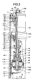
- FIG. 2 is a sectional view showing a damping force adjusting apparatus of the front fork;
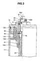
- FIG. 3 is a sectional view showing a structure of an upper portion of FIG. 2;
- FIG. 4 is a sectional view showing a structure of a lower portion of FIG. 2;
- FIGS. 5 shows a cap assembly, wherein (A) is a sectional view and (B) is a plan view;
- FIG. 6 is a sectional view showing a piston rod;
- FIG. 7 shows a first adjusting portion, wherein (A) is a sectional view and (B) is an end surface view;
- FIG. 8 is a plan view showing an engaging piece;
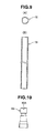
- FIGS. 9 show a push rod, wherein (A) is an end surface view and (B) is a sectional view;
- FIG. 10 is a front view showing a second adjusting portion;
- FIG. 11 is a sectional view showing an inner base;
- FIG. 12 is a side view showing a needle valve;
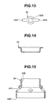
- FIG. 13 is a plan view showing a pressing piece;
- FIG. 14 is a sectional view showing a spring receiver; and
- FIG. 15 is a sectional view showing a valve retainer.
- A
front fork 10 is an inverted-type front fork in which anouter tube 11 is disposed on the side of a vehicle body and aninner tube 12 is disposed on the side of a wheel. As shown in FIGS. 1 and 2, theinner tube 12 is slidably inserted into theouter tube 11 through aguide bush 11A fixed to an inner periphery of a lower end opening of theouter tube 11 and aguide bush 12A fixed to an outer periphery of an upper end opening of theinner tube 12.Reference numeral 11B represents an oil seal, and reference numeral 11C represents a dust seal. Acap 13 is liquid-tightly threadedly engaged with the upper end opening of theouter tube 11, and theouter tube 11 is provided at its outer periphery with vehicle body-side mounting members axle bracket 15 is liquid-tightly inserted into and engaged with the lower end opening of theinner tube 12, thereby forming a bottom of theinner tube 12, and theaxle bracket 15 is provided with anaxle mounting hole 16. - The
front fork 10 defines anannular oil chamber 17 which is defined by an inner periphery of theouter tube 11, the outer periphery of theinner tube 12 and the twoguide bushes - The
front fork 10 is liquid-tightly provided with adivision wall member 19 through an O-ring on an inner periphery of the upper end of theinner tube 12. Thedivision wall member 19 defines anworking oil chamber 21 in a lower portion lower than therod guide portion 19A, and defines anoil reservoir chamber 22 in an upper portion. A lower region in theoil reservoir chamber 22 is anoil chamber 22A and an upper region in theoil reservoir chamber 22 is anair chamber 22B. - The
front fork 10 slidably inserts apiston rod 23 mounted on theouter tube 11 into therod guide portion 19A of thedivision wall member 19. More specifically, ahollow piston rod 23 is threadedly engaged with amounting collar 24 which is threadedly engaged with a lower end of a center portion of thecap 13 and is fixed by thelock nut 24A. - The
front fork 10 fixes apiston 26 which slides on an inner periphery of theinner tube 12 to apiston bolt 25 which is threadedly engaged with a tip end of thepiston rod 23 inserted into theinner tube 12 from therod guide portion 19A of thedivision wall member 19, and divides theworking oil chamber 21 into a piston rod-side oil chamber 21A in which thepiston rod 23 is accommodated and a piston-side oil chamber 21B in which thepiston rod 23 is not accommodated. Thepiston 26 is fixed by anut 27. - The
front fork 10 always brings theannular oil chamber 17 into communication with the piston rod-side oil chamber 21A through anoil hole 28 formed in theinner tube 12. - The
front fork 10 brings anupper spring receiver 31 into abutment against a lower end surface of thepiston 26 facing the piston-side oil chamber 21B, disposes alower spring receiver 32 on a bottom of theinner tube 12 formed by theaxle bracket 15, and interposes asuspension spring 33 between anupper spring receiver 31 and alower spring receiver 32. Thefront fork 10 absorbs an impact force received from a road surface when the vehicle runs by expansion and contraction vibration of asuspension spring 33. At that time, thefront fork 10 threadedly engages an adjustingnut 35 with an adjustingbolt 34 provided such as to face outside at a position (on the side of the axle mounting hole 16) deviated from theaxle mounting hole 16 of theaxle bracket 15 constituting a bottom of theinner tube 12, prevents the adjustingnut 35 from rotating by adetent washer 36 provided in theinner tube 12, disposes aslider 37 on a lower portion of thedetent washer 36 in the bottom of the inner tube, slides and guides an outer surface of the adjustingnut 35 by theslider 37, and supports a back surface of thelower spring receiver 32 through awasher 38 on a tip end of the adjustingnut 35. By turning and operating the adjustingbolt 34 from outside, the adjustingnut 35 which is prevented from rotating by thedetent washer 36 is moved straightly, and thelower spring receiver 32 supported by a back surface of the adjustingnut 35 is vertically moved. Since the adjustingbolt 34 is provided such as to face outside at the position deviated from theaxle mounting hole 16 of theinner tube 12, a spring load of thesuspension spring 33 can be adjusted without detaching thefront fork 10 from the axle. - The
piston 26 of thefront fork 10 includes a damping force generating apparatus 40 (FIG. 2). - The damping
force generating apparatus 40 includes a compression-side flow path 41 and an expansion-side flow path 42 (now shown). The compression-side flow path 41 is opened and closed by a compression-side disc valve 41A (compression-side damping valve) which is backed up by thevalve stopper 41B. The expansion-side flow path 42 is opened and closed by an expansion-side disc valve 42A (expansion-side damping valve) which is backed up by thevalve stopper 42B. Thevalve stopper 41B, thevalve 41A, thepiston 26, thevalve 42A and thevalve stopper 42B constitute a valve assembly inserted into thepiston bolt 25, and are sandwiched and fixed by thenut 27 threadedly engaged with thepiston bolt 25. - The damping
force generating apparatus 40 is provided at a center of thecap 13 with a dampingforce adjusting apparatus 40A, inserts aneedle valve 85 of the dampingforce adjusting apparatus 40A into a hollow of thepiston rod 23, and adjusts the opening degree of abypass passage 45 provided in thepiston rod 23 by a vertical movement of theneedle valve 85. Thebypass passage 45 bypasses thepiston 26, and brings the piston rod-side oil chamber 21A and the piston-side oil chamber 21B into communication with each other. - The damping
force generating apparatus 40 generates a compression-side damping force by a passage resistance of thebypass passage 45 whose opening degree is adjusted by theneedle valve 85 during a compression-side stroke, the compression-side disc valve 41A is bent and deformed in intermediate speed and high speed regions, and compression-side damping force is generated. During expansion-side stroke, in a low speed region, expansion-side damping force is generated by a passage resistance of thebypass passage 45 whose opening degree is adjusted by theneedle valve 85, the expansion-side disc valve 42A is bent and deformed in the intermediate speed and high speed regions, and the expansion-side damping force is generated. The compression-side damping force and the expansion-side damping force damp the expansion and contraction vibration of thesuspension spring 33. - The
front fork 10 fixes, to a lower end surface of thecap 13, astopper rubber 13A and astopper plate 13B against which an upper end of thedivision wall member 19 provided on theinner tube 12. Thestopper rubber 13A restricts the most compressing stroke. - A spring sheet 51 is swaged and fixed to a lower end surface of the
division wall member 19 on the side of an upper end of theinner tube 12 facing the piston rod-side oil chamber 21A. Aspring sheet 52 is retained to astopper ring 52A provided on thepiston rod 23. Thefront fork 10 interposes arebound spring 53 between the spring sheet 51 and thespring sheet 52. When thefront fork 10 is most expanded, thedivision wall member 19 presses therebound spring 53 between thedivision wall member 19 and thespring sheet 52, thereby restricting the most expanding stroke. - In the
front fork 10, a cross-sectional area S1 of theannular oil chamber 17 comprising an annular gap between theouter tube 11 and theinner tube 12 is set greater than a cross-sectional area (area surrounded by outer diameter) S2 of the piston rod 23 (S1>S2 including S1≥2). - The
rod guide portion 19A of thedivision wall member 19 is provided with acheck valve 60. Thecheck valve 60 permits oil to flow into the piston rod-side oil chamber 21A from theoil reservoir chamber 22 during the compression-side stroke, and thecheck valve 60 prevents oil from flowing into theoil reservoir chamber 22 from the piston rod-side oil chamber 21A during the expansion-side stroke. Avalve chamber 61 is provided in an inner periphery of therod guide portion 19A of thedivision wall member 19. Thecheck valve 60 is accommodated between astep 61A on an upper end side of thevalve chamber 61 and a back upspring 62 on the spring sheet 51 provided on the lower end side of thevalve chamber 61. Thecheck valve 60 is shorter than a gap between thestep 61A and the spring sheet 51, and a lateral groove is formed in the lower end surface. Thecheck valve 60 can slide on an inner periphery of thevalve chamber 61 provided on therod guide portion 19A of thedivision wall member 19 and can be displaced vertically. A flow path is formed between the outer periphery of thecheck valve 60 and the inner periphery of thevalve chamber 61 provided in therod guide portion 19A of thedivision wall member 19, and oil flows from theoil reservoir chamber 22 to the piston rod-side oil chamber 21A through this flow path. Abush 63 is press-fitted into an inner periphery of thecheck valve 60. Thebush 63 slidably supports thepiston rod 23. During the compression-side stroke, thecheck valve 60 moves together with thepiston rod 23 which enters theinner tube 12 and moves downward, and collides against the spring sheet 51, forms a gap between thecheck valve 60 and thestep 61A, so that oil in theoil reservoir chamber 22 can pass through a gap between thestep 61A through an outer periphery of the lateral groove from the lateral groove, and the oil can flow into the piston rod-side oil chamber 21A. In the expansion-side stroke, thecheck valve 60 moves together with thepiston rod 23 which retreats from theinner tube 12 and moves upward, collides against thestep 61A, closes the gap between thestep 61A, and thecheck valve 60 prevents oil in the piston rod-side oil chamber 21A from being discharged into theoil reservoir chamber 22 through a path opposite from that of the compression-side stroke. - The
rod guide portion 19A of thedivision wall member 19 does not have an oil seal around thepiston rod 23. Thus, thebush 63 which is press-fitted into the inner periphery of thecheck valve 60 constitutes a fine flow path (orifice) 64 which brings the piston rod-side oil chamber 21A and theoil reservoir chamber 22 into communication with each other by a fine gap (or fine gap formed between thecheck valve 60 and thestep 61A) formed around thepiston rod 23. The fine flow path 64 may be formed in therod guide portion 19A of thedivision wall member 19. The piston rod-side oil chamber 21A and theoil reservoir chamber 22 are in communication with each other through the fine flow path 64. - The
front fork 10 is operated in the following manner. - During the compression-side stroke, working oil of an entering capacity amount of the
piston rod 23 which enters theinner tube 12 is sent to theannular oil chamber 17 from theoil chamber 21A in the inner periphery of theinner tube 12 through theoil hole 28 of theinner tube 12. At that time, since a capacity-increase amount ΔS1 of theannular oil chamber 17 is greater than a capacity-increase amount ΔS2 of thepiston rod 23, shortfall of (ΔS1-ΔS2) of a necessary supply amount of oil to theannular oil chamber 17 is supplied from theoil reservoir chamber 22 through thecheck valve 60. - During this compression-side stroke, as described above, a compression-side damping force is generated in the low speed region by a passage resistance of the
bypass passage 45 whose opening degree is adjusted by theneedle valve 85, and in the intermediate speed and high speed regions, the compression-side disc valve 41A is bent and deformed and a compression-side damping force is generated. - In the expansion-side stroke, working oil of retreating capacity amount of the
piston rod 23 which retreats from theinner tube 12 is sent into theoil chamber 21A in the inner periphery of theinner tube 12 from theannular oil chamber 17 through theoil hole 28 of theinner tube 12. At that time, since a capacity decrease amount ΔS1 (discharge amount) of theannular oil chamber 17 is greater than a capacity decrease amount ΔS2 of thepiston rod 23, a surplus amount of (ΔS1-ΔS2) of the discharge amount of oil from theannular oil chamber 17 is discharged into theoil reservoir chamber 22 from the fine flow path 64. - During this expansion-side stroke, as described above, an expansion-side damping force is generated in the low speed region by a passage resistance of the
bypass passage 45 whose opening degree is adjusted by theneedle valve 85, and in the intermediate speed and high speed regions, the expansion-side disc valve 42A is bent and deformed and an expansion-side damping force is generated. The expansion-side damping force is also generated due to the passage resistance of the fine flow path 64. - The damping
force adjusting apparatus 40A will be explained. - As shown in FIGS. 2 to 4, in the damping
force adjusting apparatus 40A, onepush rod 70 is provided on a hollow portion of thepiston rod 23. Thepush rod 70 has a noncircular cross section (D-shaped cross section in this embodiment). Thepush rod 70 can move in the rotational direction and the axial direction. A first adjustingportion 80 which moves thepush rod 70 in the rotational direction and asecond adjusting portion 90 which moves thepush rod 70 in the axial direction are coaxially disposed on an extension of thepush rod 70 at an upper portion of thefront fork 10. Theneedle valve 85 is slidably inserted into the noncircular cross section of thepush rod 70. The dampingforce adjusting apparatus 40A threadedly engages theneedle valve 85 with the hollow portion of thepiston rod 23, theneedle valve 85 is threadedly moved by the rotation of the first adjustingportion 80, the opening degree of thebypass passage 45 is adjusted by theneedle valve 85, and the damping force can be adjusted by the passage resistance of thebypass passage 45. The dampingforce adjusting apparatus 40A biases the compression-side disc valve 41A in its closing direction by aspring 95 which collides against thepush rod 70 in the axial direction, the compression-side disc valve 41A is bent and deformed and the compression-side damping force can be adjusted. Structures of the first adjustingportion 80 and thesecond adjusting portion 90, a damping force adjusting structure using theneedle valve 85 and a damping force adjusting structure using thespring 95 will be explained. - A
cap 13 constitutes a cap assembly shown in FIGS. 5. Thecap 13 is liquid-tightly threadedly engaged with an upper end opening of theouter tube 11 through an O-ring 13C. The mountingcollar 24 is threadedly engaged with a lower end opening of thecap 13, and an upper end of thepiston rod 23 shown in FIG. 6 is threadedly engaged with the mountingcollar 24, and is fixed by thelock nut 24A. - The
first adjusting portion 80 is liquid-tightly inserted from a lower end opening of a center hole of thecap 13 through an O-ring 81. Thefirst adjusting portion 80 is engaged with an intermediate step of thecap 13 in the axial direction and is prevented from being pulled out upward, the first adjustingportion 80 axially collides against theflat washer 82 placed on an upper end surface of the mountingcollar 24 which is threadedly engaged with a lower end opening of thecap 13, the first adjustingportion 80 is prevented from being pulled out downward and as a result, the first adjustingportion 80 is rotatably provided on thecap 13 using theoperating surface 80A on the upper end outer periphery. The lower end surface of the first adjustingportion 80 which collides against theflat washer 82 includes thelateral groove 80B as shown in FIGS. 7. Bothside projections 83A of an engagingpiece 83 shown in FIG. 8 are engaged with thelateral groove 80B in the rotational direction almost without play. A pressing piece of thepush rod 70 having a noncircular cross section (D-shaped cross section) as shown in FIGS. 9 penetrates a noncircular hole (D-shaped hole) 83B formed in the center of the engagingpiece 83, the outer periphery is engaged with the engagingpiece 83 almost without play in the rotational direction, and the outer periphery can slide in the axial direction. With this, the first adjustingportion 80 can move thepush rod 70 in the rotational direction. - The
second adjusting portion 90 is liquid-tightly inserted from the lower end opening of the center hole of the first adjustingportion 80 through an O-ring 91. Thesecond adjusting portion 90 engages with the intermediate step of the first adjustingportion 80 in the axial direction and is prevented from being pulled out upward. The lower end surface of thesecond adjusting portion 90 collides against an upper end surface of thepush rod 70 without gap in the axial direction. Thepush rod 70 penetrates anoncircular hole 83B of the engagingpiece 83 which is engaged with a side of the first adjustingportion 80. Thepush rod 70 is biased upward by a spring force of the later-describedspring 95, and an upper end surface of thepush rod 70 always collides against the lower end surface of thesecond adjusting portion 90. Thesecond adjusting portion 90 is threadedly moved with respect to the first adjustingportion 80 using anoperating groove 90A in an upper end surface of thesecond adjusting portion 90 shown in FIG. 10 and thepush rod 70 can be moved in the axial direction. - The
inner base 84 shown in FIG. 11 is inserted into the lower end of the hollow portion of thepiston rod 23, and the lower end surface of thepiston rod 23 and the inner diameter step of thepiston bolt 25 sandwich and fix thelower end flange 84A of theinner base 84. Theinner base 84 may be press-fitted into the hollow portion of thepiston rod 23. Thescrew portion 85B of the intermediate portion of theneedle valve 85 shown in FIG. 12 is threadedly engaged with the inner periphery of theinner base 84 fixed to thepiston rod 23 in this manner. A noncircular crosssectional portion 85A having a noncircular cross section (D-shaped cross section in this embodiment) of the upper end of theneedle valve 85 is inserted into the noncircular cross section of the lower end of thepush rod 70 inserted into the hollow portion of thepiston rod 23 almost without play such that the noncircular crosssectional portion 85A can slide in the axial direction and is engaged in the rotational direction. - If the first adjusting
portion 80 moves thepush rod 70 in the rotational direction, theneedle valve 85 which is in engagement with thepush rod 70 in the rotational direction threadedly moves with respect to theinner base 84 on the side of thepiston rod 23, theneedle valve 85 moves forward and backward with respect to the valve sheet of the upper end of the vertical hole of thebypass passage 45 formed in thepiston bolt 25, theneedle valve 85 adjusts the opening degree of thebypass passage 45, and the compression-side damping force and the expansion-side damping force caused by the passage resistance of thebypass passage 45 can be adjusted. - When the first adjusting
portion 80 threadedly moves theneedle valve 85 through thepush rod 70, theneedle valve 85 idles with respect to thecenter hole 92B of thepressing piece 92 for the later-describedspring 95, and this does not affect thespring 95. - A
long guide hole 23A extending in the axial direction is formed in both sides of a lower end of thepiston rod 23 in the radial direction (FIG. 6), bothside projections 92A of thepressing piece 92 shown in FIG. 13 are slidably inserted into theguide hole 23A almost without play. The lower end surface of thepush rod 70 inserted into the hollow portion of thepiston rod 23 directly collides against the upper surface of thepressing piece 92, and the noncircular crosssectional portion 85A of theneedle valve 85 inserted into the lower end of thepush rod 70 is loosely inserted into acircular hole 92B formed in the center of thepressing piece 92 such that the noncircular crosssectional portion 85A can move in the axial direction. - A spring receiver 93 (FIG. 14) which collides against both
side projections 92A of thepressing piece 92 from below, and a valve retainer 94 (FIG. 14) which collides against an upper surface (back surface) of the compression-side disc valve 41A are disposed around a lower end (piston bolt 25) of thepiston rod 23. Avalve retainer spring 95 is interposed between thespring receiver 93 and thevalve retainer 94. Thespring receiver 93 is formed into a cup-like shape. An inner peripheral lower end of the cup collides against the bothside projections 92A of thepressing piece 92, and thespring 95 sits on an upper end outer peripheral flange of the cup. Thevalve retainer 94 includes anannular press portion 94A which collides against an appropriate outer diameter position of an upper surface of the compression-side disc valve 41A over the enter periphery continuously (or intermittently), aslide portion 94B which is slid and guided by an upper end outer periphery of thepiston bolt 25, and anoil passage 94C which brings the piston rod-side oil chamber 21A into communication with the compression-side flow path 41, the expansion-side flow path 42 and thebypass passage 45. Thespring 95 sits on the outer peripheral step. - If the
second adjusting portion 90 moves thepush rod 70 in the axial direction as described above, thepressing piece 92 against which the lower end surface of thepush rod 70 collides vertically moves thespring receiver 93, thevalve retainer spring 95 expands and contracts, and a set load of thespring 95 is adjusted. The set load of thespring 95 biases the compression-side disc valve 41A in its closing direction through thevalve retainer 94, and the compression-side damping force can be adjusted by the bending deformation of the compression-side disc valve 41A. Thevalve retainer 94 can be replaced by another cap having a different diameter of thepress portion 94A. Avalve retainer 94 having a largediameter press portion 94A presses an outer periphery of the compression-side disc valve 41A, and increases the damping force from a low speed region of the piston. Avalve retainer 94 having a smalldiameter press portion 94A presses an inner periphery of the compression-side disc valve 41A, and increases the damping force in the intermediate to high speed regions of the piston. - When the
second adjusting portion 90 moves thepressing piece 92 through thepush rod 70, thepush rod 70 and thepressing piece 92 idle in the axial direction with respect to the needle valve 85.This does not affect theneedle valve 85. - According to the embodiment, the following effects can be obtained.
- (a) The
first adjusting portion 80 and thesecond adjusting portion 90 are coaxially disposed on the extension of thepush rod 70 at the upper portion of thefront fork 10, the first adjustingportion 80 and thepush rod 70 can easily be coupled to each other in the rotational direction, thesecond adjusting portion 90 and thepush rod 70 can easily be coupled to each other in the axial direction, simple, the number of the parts is small, and operation failure is not easily caused in thefront fork 10. - (b) Since the first adjusting
portion 80 and thesecond adjusting portion 90 are coaxially disposed on the upper portion of thefront fork 10, this structure can be applied to afront fork 10 which can be adjusted only from the upper end surface of theouter tube 11. Since the first adjustingportion 80 and thesecond adjusting portion 90 does not have directional properties in the circumferential direction of theouter tube 11, the assembling position of to the vehicle body-side mounting members - (c) There is only one
hollow push rod 70 having the noncircular cross section, and theneedle valve 85 is slidably inserted into the noncircular cross section of thepush rod 70. Since theneedle valve 85 is accommodated in the inner diameter of thepush rod 70, no disposition space for theneedle valve 85 is required around the outer periphery of thepush rod 70, and this structure can excellently be applied to afront fork 10 having athin piston rod 23. - (d) The
first adjusting portion 80 is rotatably provided on thecap 13 of the upper portion of thefront fork 10. The engagingpiece 83 is engaged with thegroove 80B formed in the end surface of the first adjustingportion 80 in the rotational direction. The outer periphery of the noncircular cross section of thepush rod 70 can be engaged in the rotational direction with thenoncircular hole 83B formed in the engagingpiece 83, and can slide in the axial direction. Thesecond adjusting portion 90 is threadedly engaged with the center hole of the first adjustingportion 80. The end surface of thesecond adjusting portion 90 can collide in the axial direction against the end surface of thepush rod 70 which penetrates thenoncircular hole 83B of the engagingpiece 83. Therefore, the first adjustingportion 80 and thesecond adjusting portion 90 are coaxially disposed on the upper portion of thefront fork 10 in a compact manner, rotation force of the first adjustingportion 80 can easily be transmitted to thepush rod 70, and a force of thesecond adjusting portion 90 in the axial direction can be transmitted to thepush rod 70. - As heretofore explained, embodiments of the present invention have been described in detail with reference to the drawings. However, the specific configurations of the present invention are not limited to the illustrated embodiments but those having a modification of the design within the range of the presently claimed invention are also included in the present invention.
- Although the invention has been illustrated and described with respect to several exemplary embodiments thereof, it should be understood by those skilled in the art that the foregoing and various other changes, omissions and additions may be made to the present invention without departing from the spirit and scope thereof. Therefore, the present invention should not be understood as limited to the specific embodiment set out above, but should be understood to include all possible embodiments which can be encompassed within a scope of equivalents thereof with respect to the features set out in the appended claims.
Claims (6)
- A damping force adjusting apparatus of a front fork in whichan inner tube on an axle side is slidably inserted into an outer tube on a vehicle body side,the inner tube is provided at its inner periphery with a division wall member, a working oil chamber is defined in a lower portion of the division wall member, and an oil reservoir chamber is defined in an upper portion of the division wall member,a hollow piston rod mounted on the outer tube side is inserted into the working oil chamber through the division wall member, the piston rod is provided at its tip end with a piston which slides in the working oil chamber,the working oil chamber of the inner tube is divided by a piston into a piston rod-side oil chamber and a piston-side oil chamber, the two oil chambers can be in communication with a compression-side flow path and an expansion-side flow path formed in the piston, outlets of the two flow paths are respectively provided with a compression-side damping valve and an expansion-side damping valve,a hollow portion of the piston rod is provided with a bypass passage which brings the piston rod-side oil chamber and the piston-side oil chamber into communication with each other, and the bypass passage is provided with the needle valve, whereinthe hollow portion of the piston rod is provided with a push rod having a noncircular cross section, the push rod can move in the rotational direction and the axial direction,a first adjusting portion which moves the push rod in the rotational direction and a second adjusting portion which moves the push rod in the axial direction are coaxially disposed on an extension of the push rod at an upper portion of the front fork,the needle valve which is slidably inserted into the noncircular cross section of the push rod is threadedly engaged with the hollow portion of the piston rod,a spring which collides against the push rod in the axial direction biases the compression-side damping valve in its closing direction.
- The damping force adjusting apparatus of the front fork according to claim 1, wherein the first adjusting portion is rotatably provided on a cap of an upper portion of the front fork, an engaging piece is engaged in the rotational direction with a groove formed in an end surface of the first adjusting portion, an outer periphery of the push rod having a noncircular cross section is engaged in the rotational direction with a noncircular hole formed in the engaging piece, and the outer periphery of the push rod slides on the noncircular hole in the axial direction,the second adjusting portion is threadedly engaged with a center hole of the first adjusting portion, an end surface of the second adjusting portion collides against an end surface of the push rod which penetrates the noncircular hole of the engaging piece in the axial direction.
- The damping force adjusting apparatus of the front fork according to claim 2, wherein a mounting collar is threadedly engaged with a lower end opening of the cap, and an upper end of the piston rod is threadedly engaged with the mounting collar.
- The damping force adjusting apparatus of the front fork according to claim 3, wherein the first adjusting portion is liquid-tightly inserted from a lower end opening of the center hole of the cap, the first adjusting portion is engaged in the axial direction with an intermediate step provided on the center hole of the cap, a flat washer is placed on an upper end surface of the mounting collar threadedly engaged with the cap on the side of the lower end opening, and the first adjusting portion collides against the flat washer in the axial direction,the second adjusting portion is liquid-tightly inserted from the lower end opening of the center hole of the first adjusting portion, the second adjusting portion engages in the axial direction with an intermediate step formed on the center hole of the first adjusting portion, a lower end surface of the second adjusting portion collides against an upper end surface of the push rod without a gap in the axial direction.
- The damping force adjusting apparatus of the front fork according to any one of claims 1 to 4, wherein a long guide hole extending in an axial direction is formed in a lower end of the piston rod in the radial direction, and both side projections of the pressing piece are slidably inserted into the guide hole almost without a gap,the lower end surface of the push rod inserted into the hollow portion of the piston rod directly collides against an upper surface of the pressing piece, and the noncircular cross section of the needle valve inserted into the lower end of the push rod is loosely inserted into the circular hole formed in the center of the pressing piece such that the noncircular cross section can move in the axial direction.
- The damping force adjusting apparatus of the front fork according to claim 5, wherein a spring receiver which collides against the both end projections of the pressing piece from below, and a valve retainer which collides against an upper surface of the compression-side disc valve are disposed around the lower end of the piston rod, and the spring is interposed between the spring receiver and the valve retainer.
Applications Claiming Priority (1)
| Application Number | Priority Date | Filing Date | Title |
|---|---|---|---|
| JP2006049250A JP4700519B2 (en) | 2006-02-24 | 2006-02-24 | Front fork damping force adjustment device |
Publications (2)
| Publication Number | Publication Date |
|---|---|
| EP1826453A1 true EP1826453A1 (en) | 2007-08-29 |
| EP1826453B1 EP1826453B1 (en) | 2009-08-05 |
Family
ID=38085796
Family Applications (1)
| Application Number | Title | Priority Date | Filing Date |
|---|---|---|---|
| EP20060019598 Active EP1826453B1 (en) | 2006-02-24 | 2006-09-19 | Damping force adjusting apparatus of front fork |
Country Status (3)
| Country | Link |
|---|---|
| EP (1) | EP1826453B1 (en) |
| JP (1) | JP4700519B2 (en) |
| CN (1) | CN101024413B (en) |
Cited By (6)
| Publication number | Priority date | Publication date | Assignee | Title |
|---|---|---|---|---|
| US8356829B2 (en) | 2009-11-26 | 2013-01-22 | Shimano Inc. | Bicycle suspension-setting adjustor assembly |
| US9126651B2 (en) | 2010-03-04 | 2015-09-08 | Shimano Inc. | Bicycle suspension adjustor |
| EP2042770A3 (en) * | 2007-09-28 | 2016-05-11 | Showa Corporation | Hydraulic shock absorber |
| US10029530B2 (en) * | 2013-09-30 | 2018-07-24 | Showa Corporation | Pressure damper and damping force generation mechanism |
| CN116292501A (en) * | 2023-04-13 | 2023-06-23 | 济南迈瑞科精密机械有限公司 | High-frequency high-speed zero-abrasion static pressure support actuator |
| US12005990B2 (en) * | 2018-12-20 | 2024-06-11 | Hitachi Astemo, Ltd. | Hydraulic shock absorber and saddle-type vehicle |
Families Citing this family (17)
| Publication number | Priority date | Publication date | Assignee | Title |
|---|---|---|---|---|
| JP2009133412A (en) * | 2007-11-30 | 2009-06-18 | Showa Corp | Hydraulic shock absorber |
| JP2009156348A (en) * | 2007-12-26 | 2009-07-16 | Showa Corp | Hydraulic shock absorber |
| JP4965503B2 (en) * | 2008-04-28 | 2012-07-04 | 株式会社ショーワ | Hydraulic shock absorber |
| JP5660653B2 (en) * | 2009-03-25 | 2015-01-28 | 株式会社ショーワ | Hydraulic shock absorber |
| JP2011012695A (en) * | 2009-06-30 | 2011-01-20 | Showa Corp | Hydraulic shock absorber |
| JP5469592B2 (en) * | 2010-12-13 | 2014-04-16 | カヤバ工業株式会社 | Shock absorber |
| JP5116874B2 (en) * | 2011-11-22 | 2013-01-09 | 株式会社ショーワ | Hydraulic shock absorber |
| JP5843591B2 (en) * | 2011-12-09 | 2016-01-13 | Kyb株式会社 | Shock absorber |
| JP2014005864A (en) * | 2012-06-22 | 2014-01-16 | Showa Corp | Front fork device |
| JP5937948B2 (en) | 2012-10-26 | 2016-06-22 | Kyb株式会社 | Shock absorber |
| JP5937491B2 (en) * | 2012-11-15 | 2016-06-22 | 株式会社ショーワ | Shock absorber |
| US10363987B2 (en) * | 2015-06-26 | 2019-07-30 | Fox Factory, Inc. | Compression piston |
| CN105370784A (en) * | 2015-12-14 | 2016-03-02 | 四川川南减震器集团有限公司 | Temperature attenuation resisting vibration reducer |
| JP6826487B2 (en) * | 2017-04-25 | 2021-02-03 | Kybモーターサイクルサスペンション株式会社 | Front fork |
| CN108361310A (en) * | 2018-01-31 | 2018-08-03 | 辽宁工业大学 | A kind of automobile adjustment damper and its damping method of adjustment |
| DE102019108092B4 (en) | 2019-03-28 | 2022-09-01 | Thyssenkrupp Ag | Vibration damper, motor vehicle and method of assembling a vibration damper |
| JP7350040B2 (en) * | 2021-11-15 | 2023-09-25 | 日立Astemo株式会社 | Damping force generation structure |
Citations (3)
| Publication number | Priority date | Publication date | Assignee | Title |
|---|---|---|---|---|
| JP2581704Y2 (en) * | 1990-12-11 | 1998-09-24 | カヤバ工業株式会社 | Hydraulic shock absorber |
| JP2003269515A (en) | 2002-03-14 | 2003-09-25 | Showa Corp | Hydraulic shock absorber for vehicles |
| EP1544094A1 (en) * | 2003-12-16 | 2005-06-22 | Showa Corporation | Front fork of motor cycle or the like |
Family Cites Families (5)
| Publication number | Priority date | Publication date | Assignee | Title |
|---|---|---|---|---|
| JP2521836Y2 (en) * | 1991-11-15 | 1997-01-08 | 株式会社ショーワ | Hydraulic shock absorber damping force adjustment operation mechanism |
| JPH109326A (en) * | 1996-06-28 | 1998-01-13 | Showa:Kk | Inverted strut damper |
| JP4010803B2 (en) * | 2001-12-07 | 2007-11-21 | 株式会社ショーワ | Damping force adjusting device for hydraulic shock absorber |
| JP4059664B2 (en) * | 2001-12-07 | 2008-03-12 | 株式会社ショーワ | Damping force adjustment device for hydraulic shock absorber |
| CN2500594Y (en) * | 2002-01-11 | 2002-07-17 | 重庆长安减震器有限公司 | Inverted front vibration absorber |
-
2006
- 2006-02-24 JP JP2006049250A patent/JP4700519B2/en not_active Expired - Lifetime
- 2006-09-19 EP EP20060019598 patent/EP1826453B1/en active Active
- 2006-09-19 CN CN2006101388024A patent/CN101024413B/en active Active
Patent Citations (3)
| Publication number | Priority date | Publication date | Assignee | Title |
|---|---|---|---|---|
| JP2581704Y2 (en) * | 1990-12-11 | 1998-09-24 | カヤバ工業株式会社 | Hydraulic shock absorber |
| JP2003269515A (en) | 2002-03-14 | 2003-09-25 | Showa Corp | Hydraulic shock absorber for vehicles |
| EP1544094A1 (en) * | 2003-12-16 | 2005-06-22 | Showa Corporation | Front fork of motor cycle or the like |
Cited By (7)
| Publication number | Priority date | Publication date | Assignee | Title |
|---|---|---|---|---|
| EP2042770A3 (en) * | 2007-09-28 | 2016-05-11 | Showa Corporation | Hydraulic shock absorber |
| US8356829B2 (en) | 2009-11-26 | 2013-01-22 | Shimano Inc. | Bicycle suspension-setting adjustor assembly |
| US9126651B2 (en) | 2010-03-04 | 2015-09-08 | Shimano Inc. | Bicycle suspension adjustor |
| US10029530B2 (en) * | 2013-09-30 | 2018-07-24 | Showa Corporation | Pressure damper and damping force generation mechanism |
| US12005990B2 (en) * | 2018-12-20 | 2024-06-11 | Hitachi Astemo, Ltd. | Hydraulic shock absorber and saddle-type vehicle |
| CN116292501A (en) * | 2023-04-13 | 2023-06-23 | 济南迈瑞科精密机械有限公司 | High-frequency high-speed zero-abrasion static pressure support actuator |
| CN116292501B (en) * | 2023-04-13 | 2024-01-26 | 济南迈瑞科精密机械有限公司 | High-frequency high-speed static pressure supporting actuator |
Also Published As
| Publication number | Publication date |
|---|---|
| CN101024413B (en) | 2010-12-08 |
| JP4700519B2 (en) | 2011-06-15 |
| JP2007225066A (en) | 2007-09-06 |
| CN101024413A (en) | 2007-08-29 |
| EP1826453B1 (en) | 2009-08-05 |
Similar Documents
| Publication | Publication Date | Title |
|---|---|---|
| EP1826453B1 (en) | Damping force adjusting apparatus of front fork | |
| EP2042770B1 (en) | Hydraulic shock absorber | |
| US7431135B2 (en) | Stroke dependent damping | |
| US8627933B2 (en) | Two stage valve and hydraulic damped valve | |
| US20120292144A1 (en) | Nested check high speed valve | |
| US20100148412A1 (en) | Hydraulic shock absorber | |
| US6886670B2 (en) | Extra support land for valve disc | |
| WO2009032045A2 (en) | Disc spring intake | |
| US6899207B2 (en) | Extra support area for valve disc | |
| US7290643B2 (en) | Front fork in two-wheeled motor vehicle or the like | |
| US20080053764A1 (en) | Front fork | |
| US20110247906A1 (en) | Damping mechanism | |
| JP2017187109A (en) | Shock absorber | |
| EP1555199B1 (en) | Front fork of motorcycle | |
| EP1664581A1 (en) | Heavy duty base valve | |
| JP2007263324A (en) | Hydraulic shock absorber | |
| JP2009236196A (en) | Hydraulic shock absorber | |
| EP1867892B1 (en) | Hydraulic shock absorber | |
| JP2009008150A (en) | Damping force adjusting structure of hydraulic shock absorber | |
| JP4870005B2 (en) | Damping force generator | |
| JP2006283924A (en) | Hydraulic shock absorber for vehicles | |
| JPH0722149U (en) | Pressure damper damping device for hydraulic shock absorber | |
| WO2024236987A1 (en) | Shock absorber | |
| GB2437185A (en) | A shock absorber piston valve assembly | |
| JP2007333120A (en) | Damping valve of hydraulic shock absorber |
Legal Events
| Date | Code | Title | Description |
|---|---|---|---|
| PUAI | Public reference made under article 153(3) epc to a published international application that has entered the european phase |
Free format text: ORIGINAL CODE: 0009012 |
|
| AK | Designated contracting states |
Kind code of ref document: A1 Designated state(s): AT BE BG CH CY CZ DE DK EE ES FI FR GB GR HU IE IS IT LI LT LU LV MC NL PL PT RO SE SI SK TR |
|
| AX | Request for extension of the european patent |
Extension state: AL BA HR MK YU |
|
| 17P | Request for examination filed |
Effective date: 20080122 |
|
| 17Q | First examination report despatched |
Effective date: 20080225 |
|
| AKX | Designation fees paid |
Designated state(s): NL SE |
|
| REG | Reference to a national code |
Ref country code: DE Ref legal event code: 8566 |
|
| GRAP | Despatch of communication of intention to grant a patent |
Free format text: ORIGINAL CODE: EPIDOSNIGR1 |
|
| GRAS | Grant fee paid |
Free format text: ORIGINAL CODE: EPIDOSNIGR3 |
|
| GRAA | (expected) grant |
Free format text: ORIGINAL CODE: 0009210 |
|
| AK | Designated contracting states |
Kind code of ref document: B1 Designated state(s): NL SE |
|
| REG | Reference to a national code |
Ref country code: SE Ref legal event code: TRGR |
|
| PLBE | No opposition filed within time limit |
Free format text: ORIGINAL CODE: 0009261 |
|
| STAA | Information on the status of an ep patent application or granted ep patent |
Free format text: STATUS: NO OPPOSITION FILED WITHIN TIME LIMIT |
|
| 26N | No opposition filed |
Effective date: 20100507 |
|
| REG | Reference to a national code |
Ref country code: NL Ref legal event code: PD Owner name: HITACHI ASTEMO CO., LTD.; JP Free format text: DETAILS ASSIGNMENT: CHANGE OF OWNER(S), MERGE; FORMER OWNER NAME: SHOWA CORPORATION Effective date: 20211123 |
|
| REG | Reference to a national code |
Ref country code: NL Ref legal event code: PD Owner name: HITACHI ASTEMO, LTD.; JP Free format text: DETAILS ASSIGNMENT: CHANGE OF OWNER(S), MERGE; FORMER OWNER NAME: SHOWA CORPORATION Effective date: 20220121 |
|
| PGFP | Annual fee paid to national office [announced via postgrant information from national office to epo] |
Ref country code: NL Payment date: 20250814 Year of fee payment: 20 |
|
| PGFP | Annual fee paid to national office [announced via postgrant information from national office to epo] |
Ref country code: SE Payment date: 20250728 Year of fee payment: 20 |