EP1826031A1 - Method and device for locating the position of the wheels of a vehicle - Google Patents
Method and device for locating the position of the wheels of a vehicle Download PDFInfo
- Publication number
- EP1826031A1 EP1826031A1 EP07002595A EP07002595A EP1826031A1 EP 1826031 A1 EP1826031 A1 EP 1826031A1 EP 07002595 A EP07002595 A EP 07002595A EP 07002595 A EP07002595 A EP 07002595A EP 1826031 A1 EP1826031 A1 EP 1826031A1
- Authority
- EP
- European Patent Office
- Prior art keywords
- identification
- vehicle
- central unit
- signals
- programmed
- Prior art date
- Legal status (The legal status is an assumption and is not a legal conclusion. Google has not performed a legal analysis and makes no representation as to the accuracy of the status listed.)
- Withdrawn
Links
- 238000000034 method Methods 0.000 title claims abstract description 54
- 230000005540 biological transmission Effects 0.000 claims description 21
- 238000005096 rolling process Methods 0.000 claims description 3
- 238000012544 monitoring process Methods 0.000 abstract description 6
- 230000004807 localization Effects 0.000 description 21
- 230000035945 sensitivity Effects 0.000 description 4
- 230000006978 adaptation Effects 0.000 description 3
- 230000003071 parasitic effect Effects 0.000 description 3
- 241000897276 Termes Species 0.000 description 2
- 230000002159 abnormal effect Effects 0.000 description 2
- 238000005259 measurement Methods 0.000 description 2
- 244000045947 parasite Species 0.000 description 2
- 230000004043 responsiveness Effects 0.000 description 2
- 241001441732 Ostraciidae Species 0.000 description 1
- 238000001514 detection method Methods 0.000 description 1
- 238000010586 diagram Methods 0.000 description 1
- 230000005284 excitation Effects 0.000 description 1
- 230000036039 immunity Effects 0.000 description 1
- 238000009434 installation Methods 0.000 description 1
- 230000002045 lasting effect Effects 0.000 description 1
- 230000004044 response Effects 0.000 description 1
- 230000001960 triggered effect Effects 0.000 description 1
Images
Classifications
-
- B—PERFORMING OPERATIONS; TRANSPORTING
- B60—VEHICLES IN GENERAL
- B60C—VEHICLE TYRES; TYRE INFLATION; TYRE CHANGING; CONNECTING VALVES TO INFLATABLE ELASTIC BODIES IN GENERAL; DEVICES OR ARRANGEMENTS RELATED TO TYRES
- B60C23/00—Devices for measuring, signalling, controlling, or distributing tyre pressure or temperature, specially adapted for mounting on vehicles; Arrangement of tyre inflating devices on vehicles, e.g. of pumps or of tanks; Tyre cooling arrangements
- B60C23/02—Signalling devices actuated by tyre pressure
- B60C23/04—Signalling devices actuated by tyre pressure mounted on the wheel or tyre
- B60C23/0408—Signalling devices actuated by tyre pressure mounted on the wheel or tyre transmitting the signals by non-mechanical means from the wheel or tyre to a vehicle body mounted receiver
- B60C23/0415—Automatically identifying wheel mounted units, e.g. after replacement or exchange of wheels
- B60C23/0416—Automatically identifying wheel mounted units, e.g. after replacement or exchange of wheels allocating a corresponding wheel position on vehicle, e.g. front/left or rear/right
-
- B—PERFORMING OPERATIONS; TRANSPORTING
- B60—VEHICLES IN GENERAL
- B60C—VEHICLE TYRES; TYRE INFLATION; TYRE CHANGING; CONNECTING VALVES TO INFLATABLE ELASTIC BODIES IN GENERAL; DEVICES OR ARRANGEMENTS RELATED TO TYRES
- B60C23/00—Devices for measuring, signalling, controlling, or distributing tyre pressure or temperature, specially adapted for mounting on vehicles; Arrangement of tyre inflating devices on vehicles, e.g. of pumps or of tanks; Tyre cooling arrangements
- B60C23/02—Signalling devices actuated by tyre pressure
- B60C23/04—Signalling devices actuated by tyre pressure mounted on the wheel or tyre
- B60C23/0408—Signalling devices actuated by tyre pressure mounted on the wheel or tyre transmitting the signals by non-mechanical means from the wheel or tyre to a vehicle body mounted receiver
- B60C23/0422—Signalling devices actuated by tyre pressure mounted on the wheel or tyre transmitting the signals by non-mechanical means from the wheel or tyre to a vehicle body mounted receiver characterised by the type of signal transmission means
- B60C23/0433—Radio signals
- B60C23/0447—Wheel or tyre mounted circuits
- B60C23/045—Means for detecting electromagnetic field changes being not part of the signal transmission per se, e.g. strength, direction, propagation or masking
Definitions
- the invention relates to a method and a device for locating the position of wheels of a vehicle equipped with an electronic box adapted to transmit, to a central unit mounted on the vehicle, signals representative of operating parameters of the vehicle. each wheel including, in addition, an identification code of the latter.
- More and more motor vehicles have, for security purposes, surveillance systems comprising sensors mounted on each of the wheels of the vehicle, dedicated to the measurement of parameters, such as the pressure or temperature of the tires fitted to these wheels, and intended to to inform the driver of any abnormal variation of the measured parameter.
- These surveillance systems are conventionally equipped with a sensor mounted on each of the wheels of the vehicle and comprising a microprocessor and a radiofrequency transmitter (or RF transmitter), and a central unit for receiving signals emitted by the transmitters, comprising a calculator integrating a radio frequency receiver (or RF receiver) connected to an antenna.
- a sensor mounted on each of the wheels of the vehicle and comprising a microprocessor and a radiofrequency transmitter (or RF transmitter), and a central unit for receiving signals emitted by the transmitters, comprising a calculator integrating a radio frequency receiver (or RF receiver) connected to an antenna.
- a first location method consists in using three low frequency antennas positioned each close to one of the wheels of the vehicle, and in performing a localization procedure of successively exciting each of these three antennas by the emission a low frequency magnetic field.
- the sensor mounted on the wheel located near the excited antenna commands, in response to and destined for the central unit, the transmission of a low frequency signal comprising an identification code of said sensor, so that the successive excitation of the three antennas leads to the location of the three sensors mounted on the wheels adjacent to these antennas, and by deduction, to the location of the fourth sensor.
- the main advantage of such a method lies in the fact that the location procedure is very fast and leads to an almost instantaneous location after the vehicle is started.
- this solution requires to equip the vehicle with three antennas with all subjections related: connection cables, control amplifiers ..., so it is expensive.
- the implementation of this solution consists, for example, in controlling the transmission by the transmitting antennas of an uncoded signal when the said antennas are used for the purpose of locating the wheels. , and controlling the transmission of a coded signal when using the antennas to their original purpose of controlling access to the vehicle.
- the antennas of the hands-free access devices are not positioned ideally to allow the location of the wheels of a vehicle.
- the present invention aims to overcome this drawback related to the unreliability of the locating method described above, and its main purpose is to provide a very efficient locating method in terms of responsiveness and reliability.
- Another object of the invention is to provide a localization method, further requiring, for its implementation, a simple software adaptation of conventional hands-free access devices fitted to current vehicles.
- Another object of the invention is to provide a location method that does not affect the life of the power supply means embedded in the electronic boxes.
- the invention provides a method for locating the position of wheels of a vehicle equipped with an electronic box adapted to transmit, to a central unit mounted on the vehicle, signals representative of operating parameters. each wheel further comprising an identification code thereof, said locating method of equipping the vehicle with transmitting antennas each arranged to have a coverage area in which at least one wheel is located.
- the locating method according to the invention therefore consists, in the first place, in controlling the transmission, by each transmitting antenna, of a plurality of identification request signals, so that, statistically, each electronic box located in the coverage area of this transmitting antenna is necessarily solicited by an identification request.
- each electronic unit is adapted, not to respond systematically when receiving an identification request signal, but to increment a counter and control the punctual emission of a count signal representative of the number of said identification request signals actually received.
- this localization method only requires a simple software adaptation of the operation of the latter, intended to ensure the management of the counting of the identification request signals, and the transmission of counting signals.
- one of the consequences arising from the specific features of the method according to the invention lies in the possibility of advantageously using the antennas of a hands-free access device adapted to allow access to a vehicle and to start it, with a simple software adaptation of this hands-free access device consisting in particular in programming the central unit so as to adapt the latter for the implementation of the location procedure according to the invention.
- each electronic unit is programmed to periodically transmit, in a so-called "pre-rolling" phase following a vehicle starting, an identification signal incorporating the code identification of the wheel
- the method according to the invention may advantageously consist of integrating the count data in each of said identification signals.
- the localization method does not require the transmission by the electronic boxes of specific signals dedicated to the location procedure, so that it does not affect the lifetime of the power supply means embedded in the said boxes e.
- the central unit is programmed to control spot emissions of the counting signals by the electronic boxes.
- the localization procedure requires the emission of specific signals emitted by the electronic boxes.
- the number of counting required being very low, their impact on the life of the power supply means embedded in the electronic boxes is negligible.
- the central unit is programmed, for each transmitting antenna, to perform the calculation of the ratio at the end of the n transmissions of the request signal of identification.
- the central unit can also be programmed, for each transmitting antenna, to perform at least one intermediate ratio calculation, and to control the interruption of the transmissions of the identification request signal when said calculated intermediate ratio is greater than the predetermined threshold value.
- This second implementation variant makes it possible, in fact, to shorten the transmission time, by each transmitting antenna, identification request signals, and thus leads to reduce the overall duration of the location procedure.
- the central unit is programmed to emit a reset signal of the count of the identification request signals received by the electronic boxes.
- This embodiment essentially makes it possible to manage the applications according to which at least one electronic box is located in the coverage area of two transmitting antennas successively used during the localization procedure.
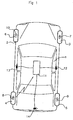
- the locating device according to the invention shown by way of example in FIG. 1 is intended for locating the position of wheels of a vehicle.
- This locating device is more specifically intended to be installed on vehicles equipped with a surveillance system such as that shown in Figure 1, equipping a vehicle 1 provided with four wheels conventionally paved with a tire: two front wheels 2 , 3 and two rear wheels 4, 5.
- Such monitoring systems conventionally comprise, firstly, associated with each wheel 2-5, an electronic box 6-9, for example secured to the rim of said wheel so as to be positioned inside the envelope of the tire.
- Each of these electronic boxes 6-9 includes, for example, sensors dedicated to the measurement of parameters, such as pressure and / or temperature of the tire, connected to a microprocessor having an identification code of said housing, and connected to a RF transmitter connected to a low frequency antenna such as 10.
- the monitoring system also comprises a centralized computer or central unit 11 comprising a microprocessor and integrating an RF receiver adapted to receive the signals emitted by each of the four electronic boxes 6-9.
- such a monitoring system and in particular its central unit 11 are designed to inform the driver of any abnormal variation of the parameters measured by the sensors associated with the wheels 2-5.
- the locating device according to the invention also comprises transmitting antennas 12-14 connected to the central unit 11 and each disposed near a pair of left wheels 2, 4, right 3, 5, or rear 4, 5.
- these transmitting antennas 12 - 14 consist of antennas of a device usually known as the "hands-free access device", adapted to allow access to the vehicle 1 and possibly start the latter through the identification of an electronic badge.
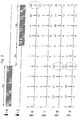
- FIG. 2 illustrates an exemplary localization procedure implemented by means of the locating device described above, consisting of successively using two antennas, in the example the rear antenna 14 and then the left antenna 13, with a view to the transmission of the identification request signals.
- the central unit 11 controls the transmission by each transmitting antenna 13, 14 of one hundred identification request signals transmitted with a frequency of five signals per second, so that the transmission duration of each of said transmitting antennas is equal to twenty seconds.
- the numerical values mentioned above can be modified without departing from the scope of the present invention.
- the switching between the two transmitting antennas 14, 13 leads to a usual "floating" period of a duration of the order of ten seconds, resulting from known conventional material contingencies. in themselves.
- the overall duration of the location procedure has a value of the order of fifty seconds.
- this periodicity of five seconds corresponds to the traditional transmission periodicity with which, at present, the electronic boxes 6-9 are programmed to transmit data frames incorporating the identification code, during an initial phase. , called “pre-rolling", intervening after the switching of said electronic boxes between a "standby” state corresponding to a stopped state of the vehicle 1, and an "awake” state triggered upon detection of a start of the said vehicle.
- this central unit 11 is also programmed to control a reset of the count of the identification request signals received by the electronic boxes 6-9, at each switching between the transmitting antennas, for example during the switching between the transmitting antennas 14 and 13.
Abstract
Description
L'invention concerne un procédé et un dispositif de localisation de la position de roues d'un véhicule équipées d'un boîtier électronique adapté pour émettre, à destination d'une unité centrale montée sur le véhicule, des signaux représentatifs de paramètres de fonctionnement de chaque roue comportant, en outre, un code d'identification de cette dernière.The invention relates to a method and a device for locating the position of wheels of a vehicle equipped with an electronic box adapted to transmit, to a central unit mounted on the vehicle, signals representative of operating parameters of the vehicle. each wheel including, in addition, an identification code of the latter.
De plus en plus de véhicules automobiles possèdent, à des fins de sécurité, des systèmes de surveillance comportant des capteurs montés sur chacune des roues du véhicule, dédiés à la mesure de paramètres, tels que pression ou température des pneumatiques équipant ces roues, et destinés à informer le conducteur de toute variation anormale du paramètre mesuré.More and more motor vehicles have, for security purposes, surveillance systems comprising sensors mounted on each of the wheels of the vehicle, dedicated to the measurement of parameters, such as the pressure or temperature of the tires fitted to these wheels, and intended to to inform the driver of any abnormal variation of the measured parameter.
Ces systèmes de surveillance sont classiquement dotés d'un capteur monté sur chacune des roues du véhicule et comportant un microprocesseur et un émetteur radiofréquence (ou émetteur RF), et d'une unité centrale de réception des signaux émis par les émetteurs, comportant un calculateur intégrant un récepteur radiofréquence (ou récepteur RF) connecté à une antenne.These surveillance systems are conventionally equipped with a sensor mounted on each of the wheels of the vehicle and comprising a microprocessor and a radiofrequency transmitter (or RF transmitter), and a central unit for receiving signals emitted by the transmitters, comprising a calculator integrating a radio frequency receiver (or RF receiver) connected to an antenna.
Un des problèmes que nécessitent de résoudre de tels systèmes de surveillance réside dans l'obligation de devoir associer à chaque signal reçu par le récepteur de l'unité centrale, une information concernant la localisation du capteur et donc de la roue à l'origine de ce signal, cette obligation perdurant pendant la durée de vie du véhicule, c'est à dire devant être respectée même après des changements de roues ou plus simplement des inversions de la position de ces roues.One of the problems that such monitoring systems need to solve lies in the obligation of having to associate with each signal received by the receiver of the central unit, information concerning the location of the sensor and therefore of the wheel causing the this signal, this obligation lasting during the life of the vehicle, ie to be respected even after wheel changes or simply inversions of the position of these wheels.
A l'heure actuelle, une première méthode de localisation consiste à utiliser trois antennes basse fréquence positionnées chacune à proximité d'une des roues du véhicule, et à effectuer une procédure de localisation consistant à exciter successivement chacune de ces trois antennes par l'émission d'un champ magnétique basse fréquence.At present, a first location method consists in using three low frequency antennas positioned each close to one of the wheels of the vehicle, and in performing a localization procedure of successively exciting each of these three antennas by the emission a low frequency magnetic field.
Selon cette procédure, le capteur monté sur la roue située à proximité de l'antenne excitée commande, en réponse et à destination de l'unité centrale, l'émission d'un signal basse fréquence comportant un code d'identification du dit capteur, de sorte que l'excitation successive des trois antennes conduit à la localisation des trois capteurs montés sur les roues jouxtant ces antennes, et par déduction, à la localisation du quatrième capteur.According to this procedure, the sensor mounted on the wheel located near the excited antenna commands, in response to and destined for the central unit, the transmission of a low frequency signal comprising an identification code of said sensor, so that the successive excitation of the three antennas leads to the location of the three sensors mounted on the wheels adjacent to these antennas, and by deduction, to the location of the fourth sensor.
Le principal avantage d'un tel procédé réside dans le fait que la procédure de localisation est très rapide et conduit à une localisation quasi-instantanée après le démarrage du véhicule.The main advantage of such a method lies in the fact that the location procedure is very fast and leads to an almost instantaneous location after the vehicle is started.
Par contre, cette solution impose d'équiper le véhicule de trois antennes avec toutes les sujétions afférentes : câbles de connexion, amplificateurs de commande..., de sorte qu'elle s'avère coûteuse.By cons, this solution requires to equip the vehicle with three antennas with all subjections related: connection cables, control amplifiers ..., so it is expensive.
Cet inconvénient relatif au coût d'installation des moyens de mise en oeuvre du procédé de localisation peut être résolu lorsque le véhicule est équipé d'un dispositif d'accès mains libres destiné à permettre d'accéder au dit véhicule et de démarrer ce dernier.This disadvantage relative to the installation cost of the implementation means of the locating method can be solved when the vehicle is equipped with a hands-free access device intended to allow access to said vehicle and start the latter.
En effet, la solution consiste alors, tel que notamment décrit dans la demande de brevet
Tel que décrit dans la demande de brevet précitée, la mise en oeuvre de cette solution consiste, par exemple, à commander l'émission par les antennes émettrices d'un signal non codé lorsque les dites antennes sont utilisées en vue de la localisation des roues, et à commander l'émission d'un signal codé lors de l'utilisation des antennes à leur fin originale de contrôle de l'accès au véhicule.As described in the above-mentioned patent application, the implementation of this solution consists, for example, in controlling the transmission by the transmitting antennas of an uncoded signal when the said antennas are used for the purpose of locating the wheels. , and controlling the transmission of a coded signal when using the antennas to their original purpose of controlling access to the vehicle.
Une telle solution très séduisante en théorie s'avère par contre très délicate à mettre en oeuvre dans la pratique. En effet, les antennes des dispositifs d'accès mains libres ne sont pas positionnées de façon idéale en vue de permettre la localisation des roues d'un véhicule.Such a very attractive solution in theory proves on the other hand very difficult to implement in practice. Indeed, the antennas of the hands-free access devices are not positioned ideally to allow the location of the wheels of a vehicle.
De ce fait, et en premier lieu, le caractère sélectif de cette localisation ne peut être obtenu que moyennant des réglages très précis de la puissance d'émission des antennes, et impose généralement d'augmenter la sensibilité des récepteurs montés sur les roues, avec pour conséquence une sensibilité de ces capteurs aux perturbations extérieures.Therefore, and firstly, the selective nature of this location can be obtained only with very precise settings of the transmit power of the antennas, and generally requires increasing the sensitivity of the receivers mounted on the wheels, with as a consequence, the sensitivity of these sensors to external disturbances.
Dans la pratique, ces conditions extrêmes de réglage conduisent fréquemment à des problèmes d'immunité au bruit et de tolérance de sensibilité des capteurs, dont découle une fiabilité très relative du procédé de localisation.In practice, these extreme tuning conditions frequently lead to problems of noise immunity and sensitivity tolerance of the sensors, which results in a very relative reliability of the location method.
La présente invention vise à pallier cet inconvénient lié au défaut de fiabilité du procédé de localisation ci-dessus décrit, et a pour principal objectif de fournir un procédé de localisation très performant en termes de réactivité et de fiabilité.The present invention aims to overcome this drawback related to the unreliability of the locating method described above, and its main purpose is to provide a very efficient locating method in terms of responsiveness and reliability.
Un autre objectif de l'invention est de fournir un procédé de localisation, nécessitant en outre, en vue de sa mise en oeuvre, une simple adaptation logicielle des dispositifs classiques d'accès mains libres équipant les véhicules actuels.Another object of the invention is to provide a localization method, further requiring, for its implementation, a simple software adaptation of conventional hands-free access devices fitted to current vehicles.
Un autre objectif de l'invention est de fournir un procédé de localisation qui n'affecte pas la durée de vie des moyens d'alimentation électrique embarqués dans les boîtiers électroniques.Another object of the invention is to provide a location method that does not affect the life of the power supply means embedded in the electronic boxes.
A cet effet, l'invention vise un procédé de localisation de la position de roues d'un véhicule équipées d'un boîtier électronique adapté pour émettre, à destination d'une unité centrale montée sur le véhicule, des signaux représentatifs de paramètres de fonctionnement de chaque roue comportant, en outre, un code d'identification de cette dernière, le dit procédé de localisation consistant à équiper le véhicule d'antennes émettrices disposées chacune de façon à présenter une zone de couverture dans laquelle est située au moins une roue.For this purpose, the invention provides a method for locating the position of wheels of a vehicle equipped with an electronic box adapted to transmit, to a central unit mounted on the vehicle, signals representative of operating parameters. each wheel further comprising an identification code thereof, said locating method of equipping the vehicle with transmitting antennas each arranged to have a coverage area in which at least one wheel is located.
Selon l'invention, ce procédé de localisation consiste à mettre en oeuvre une procédure de localisation selon laquelle, successivement pour chacune des antennes émettrices :
- l'unité centrale commande n émissions successives, par la dite antenne émettrice, d'un signal de requête d'identification,
- chaque boîtier électronique procède à une comptabilisation du nombre de signaux de requête d'identification reçus par le dit boîtier électronique, et commande ponctuellement l'émission d'au moins un signal de comptage incorporant le nombre m des dits signaux de requête d'identification reçus,
- et l'unité centrale est programmée, pour chaque boîtier électronique, pour :
- calculer un ratio représentatif du nombre de signaux de requête d'identification comptabilisés reçus par le dit boîtier électronique par rapport au nombre de signaux de requête d'identification effectivement émis par l'antenne émettrice,
- et fournir une information de présence du dit boîtier électronique dans la zone de couverture de l'antenne émettrice, lorsque le ratio calculé est supérieur à une valeur seuil déterminée.
- the central unit controls n successive transmissions, by said transmitting antenna, of an identification request signal,
- each electronic unit carries out an accounting of the number of identification request signals received by said electronic box, and punctually orders the emission of at least one counting signal incorporating the number m of said identification request signals received ,
- and the central unit is programmed, for each electronic box, for:
- calculating a ratio representative of the number of counted identification request signals received by said electronic box with respect to the number of identification request signals actually transmitted by the transmitting antenna,
- and providing information of presence of said electronic box in the coverage area of the transmitting antenna, when the calculated ratio is greater than a determined threshold value.
Le procédé de localisation selon l'invention consiste donc, en premier lieu, à commander l'émission, par chaque antenne émettrice, d'une pluralité de signaux de requête d'identification, de sorte que, statistiquement, chaque boîtier électronique situé dans la zone de couverture de cette antenne émettrice est obligatoirement sollicité par une requête d'identification.The locating method according to the invention therefore consists, in the first place, in controlling the transmission, by each transmitting antenna, of a plurality of identification request signals, so that, statistically, each electronic box located in the coverage area of this transmitting antenna is necessarily solicited by an identification request.
De plus, chaque boîtier électronique est adapté, non pas pour répondre systématiquement lors de la réception d'un signal de requête d'identification, mais pour incrémenter un compteur et commander l'émission ponctuelle d'un signal de comptage représentatif du nombre des dits signaux de requête d'identification effectivement reçus.In addition, each electronic unit is adapted, not to respond systematically when receiving an identification request signal, but to increment a counter and control the punctual emission of a count signal representative of the number of said identification request signals actually received.
Selon ce principe, le caractère sélectif de la procédure de localisation résulte du fait que :
- seuls les boîtiers électroniques situés dans la zone de couverture d'une antenne émettrice reçoivent un nombre de signaux de requête d'identification susceptible de conduire à leur identification,
- la réception, par un boîtier électronique situé à l'extérieur de la zone de couverture d'une antenne émettrice, de signaux de requête d'identification « parasites », n'a aucune répercussion, du fait que ces signaux « parasites » sont automatiquement « filtrés ».
- only the electronic boxes located in the coverage area of a transmitting antenna receive a number of identification request signals likely to lead to their identification,
- the reception, by an electronic unit located outside the coverage area of a transmitting antenna, of "parasitic" identification request signals has no repercussion, because these "parasitic" signals are automatically "Filtered".
De ce fait, un tel procédé de localisation permet de travailler à des niveaux de sensibilité élevés des récepteurs montés sur les roues tout en garantissant une insensibilité vis-à-vis des signaux « parasites » et des perturbations électromagnétiques extérieures, ces données se traduisant avantageusement, dans la pratique, par l'obtention d'un procédé de localisation très performant en termes de réactivité et de fiabilité.As a result, such a locating method makes it possible to work at high sensitivity levels of the receivers mounted on the wheels while guaranteeing insensitivity to "parasitic" signals and external electromagnetic disturbances, these data being translated advantageously. in practice, by obtaining a very efficient localization method in terms of responsiveness and reliability.
En outre, concernant les boîtiers électroniques, ce procédé de localisation ne requiert qu'une simple adaptation logicielle du fonctionnement de ces derniers, destinée à permettre d'assurer la gestion du comptage des signaux de requête d'identification, et de l'émission des signaux de comptage.In addition, concerning the electronic boxes, this localization method only requires a simple software adaptation of the operation of the latter, intended to ensure the management of the counting of the identification request signals, and the transmission of counting signals.
En outre, une des conséquences découlant des spécificités du procédé selon l'invention, réside dans la possibilité d'utiliser avantageusement les antennes d'un dispositif d'accès mains libres adapté pour permettre d'accéder à un véhicule et de démarrer ce dernier, moyennant une simple adaptation logicielle de ce dispositif d'accès mains libres consistant notamment à programmer l'unité centrale de façon à adapter cette dernière en vue de la mise en oeuvre de la procédure de localisation selon l'invention.In addition, one of the consequences arising from the specific features of the method according to the invention lies in the possibility of advantageously using the antennas of a hands-free access device adapted to allow access to a vehicle and to start it, with a simple software adaptation of this hands-free access device consisting in particular in programming the central unit so as to adapt the latter for the implementation of the location procedure according to the invention.
Dans l'hypothèse où, de façon usuelle connue en soi, chaque boîtier électronique est programmé pour émettre périodiquement, dans une phase dite de « pré-roulage » faisant suite à un démarrage d'un véhicule, un signal d'identification incorporant le code d'identification de la roue, le procédé selon l'invention peut avantageusement consister à intégrer la donnée de comptage dans chacun des dits signaux d'identification.Assuming that, in a manner known per se, each electronic unit is programmed to periodically transmit, in a so-called "pre-rolling" phase following a vehicle starting, an identification signal incorporating the code identification of the wheel, the method according to the invention may advantageously consist of integrating the count data in each of said identification signals.
Ainsi, le procédé de localisation ne requiert pas l'émission par les boîtiers électroniques de signaux spécifiques dédiés à la procédure de localisation, de sorte qu'il n'affecte pas la durée de vie des moyens d'alimentation électrique embarqués dans les dits boîtiers électroniques.Thus, the localization method does not require the transmission by the electronic boxes of specific signals dedicated to the location procedure, so that it does not affect the lifetime of the power supply means embedded in the said boxes e.
Selon une variante de mise en oeuvre avantageuse du procédé selon l'invention, l'unité centrale est programmée pour commander des émissions ponctuelles des signaux de comptage par les boîtiers électroniques.According to an advantageous variant embodiment of the method according to the invention, the central unit is programmed to control spot emissions of the counting signals by the electronic boxes.
Selon ce principe, la procédure de localisation requiert l'émission de signaux spécifiques émis par les boîtiers électroniques. Toutefois, le nombre de signaux de comptage requis étant très faible, leur répercussion sur la durée de vie des moyens d'alimentation électrique embarqués dans les boîtiers électroniques s'avère négligeable.According to this principle, the localization procedure requires the emission of specific signals emitted by the electronic boxes. However, the number of counting required being very low, their impact on the life of the power supply means embedded in the electronic boxes is negligible.
Par ailleurs, selon une première variante avantageuse de mise en oeuvre du procédé de localisation selon l'invention, l'unité centrale est programmée, pour chaque antenne émettrice, pour effectuer le calcul du ratio au terme des n émissions du signal de requête d'identification.Moreover, according to a first advantageous variant of implementation of the localization method according to the invention, the central unit is programmed, for each transmitting antenna, to perform the calculation of the ratio at the end of the n transmissions of the request signal of identification.
Selon une seconde variante avantageuse de mise en oeuvre du procédé de localisation selon l'invention, l'unité centrale peut également être programmée, pour chaque antenne émettrice, pour effectuer au moins un calcul intermédiaire de ratio, et pour commander l'interruption des n émissions du signal de requête d'identification lorsque le dit ratio intermédiaire calculé est supérieur à la valeur seuil prédéterminée.According to a second advantageous variant of implementation of the localization method according to the invention, the central unit can also be programmed, for each transmitting antenna, to perform at least one intermediate ratio calculation, and to control the interruption of the transmissions of the identification request signal when said calculated intermediate ratio is greater than the predetermined threshold value.
Cette seconde variante de mise en oeuvre permet, en effet, d'écourter la durée d'émission, par chaque antenne émettrice, des signaux de requête d'identification, et conduit donc à réduire la durée globale de la procédure de localisation.This second implementation variant makes it possible, in fact, to shorten the transmission time, by each transmitting antenna, identification request signals, and thus leads to reduce the overall duration of the location procedure.
Selon un autre mode de mise en oeuvre avantageux du procédé selon l'invention, lors de chaque commutation entre deux antennes émettrices, l'unité centrale est programmée pour émettre un signal de remise à zéro du comptage des signaux de requête d'identification reçus par les boîtiers électroniques.According to another advantageous embodiment of the method according to the invention, during each switching between two transmitting antennas, the central unit is programmed to emit a reset signal of the count of the identification request signals received by the electronic boxes.
Ce mode de mise en oeuvre permet, en effet essentiellement, de gérer les applications selon lesquelles au moins un boîtier électronique est situé dans la zone de couverture de deux antennes émettrices utilisées successivement lors de la procédure de localisationThis embodiment essentially makes it possible to manage the applications according to which at least one electronic box is located in the coverage area of two transmitting antennas successively used during the localization procedure.
D'autres caractéristiques buts et avantages de l'invention ressortiront de la description détaillée qui suit en référence aux dessins annexés qui en représentent à titre d'exemple non limitatif un mode de réalisation préférentiel. Sur ces dessins :
- la figure 1 est une vue de dessus schématique d'un véhicule doté d'un système de surveillance associé à un dispositif selon l'invention de localisation des quatre roues du dit véhicule,
- et la figure 2 est un schéma synoptique illustrant le déroulement d'une procédure de localisation mise en oeuvre selon le procédé de l'invention.
- FIG. 1 is a diagrammatic plan view of a vehicle equipped with a monitoring system associated with a device according to the invention for locating the four wheels of said vehicle,
- and FIG. 2 is a block diagram illustrating the progress of a localization procedure implemented according to the method of the invention.
Le dispositif de localisation selon l'invention représenté à titre d'exemple à la figure 1 est destiné à la localisation de la position de roues d'un véhicule.The locating device according to the invention shown by way of example in FIG. 1 is intended for locating the position of wheels of a vehicle.
Ce dispositif de localisation est plus spécifiquement destiné à être installé sur des véhicules dotés d'un système de surveillance tel que celui, représenté à la figure 1, équipant un véhicule 1 muni de quatre roues chaussées classiquement d'un pneumatique : deux roues avant 2, 3 et deux roues arrière 4, 5.This locating device is more specifically intended to be installed on vehicles equipped with a surveillance system such as that shown in Figure 1, equipping a
De tels systèmes de surveillance comportent classiquement, en premier lieu, associé à chaque roue 2-5, un boîtier électronique 6-9, par exemple solidarisé sur la jante de la dite roue de façon à être positionné à l'intérieur de l'enveloppe du pneumatique.Such monitoring systems conventionally comprise, firstly, associated with each wheel 2-5, an electronic box 6-9, for example secured to the rim of said wheel so as to be positioned inside the envelope of the tire.
Chacun de ces boîtiers électroniques 6-9 intègre, par exemple, des capteurs dédiés à la mesure de paramètres, tels que pression et/ou température du pneumatique, connectés à un microprocesseur possédant un code d'identification du dit boîtier, et relié à un émetteur RF connecté à une antenne basse fréquence telle que 10.Each of these electronic boxes 6-9 includes, for example, sensors dedicated to the measurement of parameters, such as pressure and / or temperature of the tire, connected to a microprocessor having an identification code of said housing, and connected to a RF transmitter connected to a low frequency antenna such as 10.
Le système de surveillance comprend, également, un calculateur centralisé ou unité centrale 11 comportant un microprocesseur et intégrant un récepteur RF apte à recevoir les signaux émis par chacun des quatre boîtiers électroniques 6-9.The monitoring system also comprises a centralized computer or
De façon usuelle, un tel système de surveillance et notamment son unité centrale 11 sont conçus de façon à informer le conducteur de toute variation anormale des paramètres mesurés par les capteurs associés aux roues 2-5.In the usual way, such a monitoring system and in particular its
Le dispositif de localisation selon l'invention comprend également des antennes émettrices 12-14 connectées à l'unité centrale 11 et disposées chacune à proximité d'une paire de roues gauche 2, 4, droite 3, 5, ou arrière 4, 5.The locating device according to the invention also comprises transmitting antennas 12-14 connected to the
Selon le dispositif de localisation représenté à la figure 1, ces antennes émettrices 12-14 sont constituées d'antennes d'un dispositif usuellement connu sous l'appellation « dispositif d'accès mains libres », adapté pour permettre d'accéder au véhicule 1 et éventuellement de démarrer ce dernier grâce à l'identification d'un badge électronique.According to the locating device represented in FIG. 1, these transmitting antennas 12 - 14 consist of antennas of a device usually known as the "hands-free access device", adapted to allow access to the
Conformément aux dispositions d'un tel dispositif d'accès mains libres, ces antennes peuvent être, tel que représenté à la figure 1, au nombre de trois, et consister respectivement en :
- une antenne droite 12 positionnée sur la poignée de la porte avant droite du véhicule,
- une antenne gauche 13 positionnée sur la poignée de la porte avant gauche du véhicule,
- et une antenne arrière 14 positionnée sur la poignée de la porte du coffre du véhicule.
- a
right antenna 12 positioned on the handle of the right front door of the vehicle, - a
left antenna 13 positioned on the handle of the left front door of the vehicle, - and a
rear antenna 14 positioned on the handle of the trunk door of the vehicle.
La figure 2 illustre un exemple de procédure de localisation mise en oeuvre au moyen du dispositif de localisation ci-dessus décrit, consistant à utiliser successivement deux antennes, en l'exemple l'antenne arrière 14 puis l'antenne gauche 13, en vue de l'émission des signaux de requête d'identification.FIG. 2 illustrates an exemplary localization procedure implemented by means of the locating device described above, consisting of successively using two antennas, in the example the
Selon cette procédure de localisation, l'unité centrale 11 commande l'émission par chaque antenne émettrice 13, 14 de cent signaux de requête d'identification émis avec une fréquence de cinq signaux par seconde, de sorte que la durée d'émission de chacune des dites antennes émettrices est égale à vingt secondes. Bien entendu, les valeurs numériques ci-dessus précisées peuvent être modifiées sans pour cela sortir du cadre de la présente invention.According to this localization procedure, the
De plus, et tel qu'illustré à la figure 2, la commutation entre les deux antennes émettrices 14,13 conduit à une période de « flottement » usuelle d'une durée de l'ordre de dix secondes, résultant de contingences matérielles classiques connues en elles mêmes.In addition, and as illustrated in FIG. 2, the switching between the two transmitting
Ainsi, la durée globale de la procédure de localisation présente une valeur de l'ordre de cinquante secondes.Thus, the overall duration of the location procedure has a value of the order of fifty seconds.
Selon la procédure de localisation selon l'invention, chacun des boîtiers électroniques 6-9 est, quant à lui, programmé pour :
- comptabiliser les signaux de requête d'identification effectivement reçus par le dit boîtier électronique, par incrémentation d'un compteur,
- et émettre, avec une périodicité de cinq secondes, des trames de données incorporant, d'une part, le code d'identification de la roue 2-5 correspondante, et d'autre part, selon l'invention, la valeur comptabilisée.
- counting the identification request signals actually received by said electronic box, by incrementing a counter,
- and transmit, with a period of five seconds, data frames incorporating, on the one hand, the identification code of the corresponding wheel 2-5, and on the other hand, according to the invention, the value recorded.
Il est à noter que cette périodicité de cinq secondes correspond à la périodicité classique d'émission avec laquelle, actuellement, les boîtiers électroniques 6-9 sont programmés pour émettre des trames de données incorporant le code d'identification, lors d'une phase initiale, dite de « pré-roulage », intervenant après la commutation des dits boîtiers électroniques entre un état "de veille" correspondant à un état arrêté du véhicule 1, et un état « réveillé » déclenché lors de la détection d'un démarrage du dit véhicule.It should be noted that this periodicity of five seconds corresponds to the traditional transmission periodicity with which, at present, the electronic boxes 6-9 are programmed to transmit data frames incorporating the identification code, during an initial phase. , called "pre-rolling", intervening after the switching of said electronic boxes between a "standby" state corresponding to a stopped state of the
En dernier lieu, selon la procédure de localisation selon l'invention, l'unité centrale 11 est programmée, au terme de la période d'émission globale de chaque antenne émettrice 14, 13, et pour chaque boîtier électronique 6-9 :
- pour calculer un ratio représentatif du nombre de signaux de requête d'identification comptabilisés reçus par le dit boîtier électronique par rapport au nombre de signaux de requête d'identification, (en l'exemple cent signaux), effectivement émis
par l'antenne émettrice - et pour fournir une information de présence du dit boîtier électronique dans la zone de couverture de l'antenne émettrice 14, 13, lorsque le ratio calculé est supérieur à une valeur seuil déterminée.
- to calculate a ratio representative of the number of counted identification request signals received by said electronic box with respect to the number of identification request signals, (in the example hundred signals), effectively transmitted by the transmitting
antenna - and to provide a presence information of said electronic box in the coverage area of the transmitting
antenna
De plus, cette unité centrale 11 est également programmée pour commander une remise à zéro du comptage des signaux de requête d'identification reçus par les boîtiers électroniques 6-9, lors de chaque commutation entre les antennes émettrices, en l'exemple lors de la commutation entre les antennes émettrices 14 et 13.In addition, this
Selon l'exemple représenté à la figure 2, une telle procédure de localisation conduit :
- au terme de l'émission des signaux de requête d'identification
par l'antenne arrière 14, à déterminer que les boîtiers électroniques 8et 9 équipent les roues arrière 4et 5 du véhicule 1, - et au terme de l'émission des signaux de requête d'identification par l'antenne gauche 13, à déterminer que les boîtiers électroniques 6
et 8 équipent les roues gauche 2et 4 du véhicule 1.
- at the end of the transmission of the identification request signals by the
rear antenna 14, to determine that theelectronic boxes rear wheels vehicle 1, - and at the end of the transmission of the identification request signals by the
left antenna 13, to determine that theelectronic boxes left wheels vehicle 1.
Sur la base de ces données, l'unité centrale 11 peut :
- directement déterminer que le boîtier électronique 8 équipe la roue arrière gauche 4 du véhicule 1,
- déduire de cette première localisation, respectivement, que le boîtier électronique 6 équipe la roue avant gauche 2 du véhicule 1, et que le boîtier électronique 9 équipe la roue arrière droite 5 du véhicule 1,
- et enfin, déduire des précédentes localisations, que le boîtier électronique 7 restant, équipe la roue avant droite 3 du véhicule 1.
- directly determine that the
electronic unit 8 equips the leftrear wheel 4 of thevehicle 1, - deduce from this first location, respectively, that the
electronic control unit 6 equips the leftfront wheel 2 of thevehicle 1, and that thecontrol unit 9 equips the rightrear wheel 5 of thevehicle 1, - and finally, deduce from the previous locations, that the remaining
electronic box 7, equips the frontright wheel 3 of thevehicle 1.
Claims (7)
Applications Claiming Priority (1)
| Application Number | Priority Date | Filing Date | Title |
|---|---|---|---|
| FR0601733A FR2897811B1 (en) | 2006-02-28 | 2006-02-28 | METHOD AND DEVICE FOR LOCATING THE POSITION OF WHEELS OF A VEHICLE |
Publications (1)
| Publication Number | Publication Date |
|---|---|
| EP1826031A1 true EP1826031A1 (en) | 2007-08-29 |
Family
ID=37114414
Family Applications (1)
| Application Number | Title | Priority Date | Filing Date |
|---|---|---|---|
| EP07002595A Withdrawn EP1826031A1 (en) | 2006-02-28 | 2007-02-07 | Method and device for locating the position of the wheels of a vehicle |
Country Status (3)
| Country | Link |
|---|---|
| US (1) | US7683766B2 (en) |
| EP (1) | EP1826031A1 (en) |
| FR (1) | FR2897811B1 (en) |
Cited By (3)
| Publication number | Priority date | Publication date | Assignee | Title |
|---|---|---|---|---|
| FR2956768A1 (en) * | 2010-02-22 | 2011-08-26 | Continental Automotive France | Wheel locating method for use during monitoring of state of tire of wheel in car, involves comparing sectoral ratio with value ranges stored in coverage map that associates value ranges to positions of wheels, to locate wheels |
| FR2967539A1 (en) * | 2010-11-16 | 2012-05-18 | Continental Automotive France | METHOD FOR LOCATING THE WHEELS OF A VEHICLE EQUIPPED WITH A SYSTEM FOR MONITORING THE PRESSURE OF TIRES |
| FR2998516A1 (en) * | 2012-11-29 | 2014-05-30 | Continental Automotive France | DEVICE FOR LOCATING WHEELS OF A VEHICLE EQUIPPED WITH AN ELECTRONIC HOUSING |
Families Citing this family (6)
| Publication number | Priority date | Publication date | Assignee | Title |
|---|---|---|---|---|
| CN101374274A (en) * | 2007-08-24 | 2009-02-25 | 深圳富泰宏精密工业有限公司 | Positioning system and method for virtual society group |
| US8907765B2 (en) * | 2007-12-24 | 2014-12-09 | Hewlett-Packard Development Company, L. P. | RFID tag detection method and system |
| FR2931950B1 (en) * | 2008-05-27 | 2016-02-12 | Continental Automotive France | METHOD FOR LOCATING THE POSITION OF WHEELS OF A VEHICLE |
| US8115613B2 (en) * | 2008-07-18 | 2012-02-14 | Ford Global Technologies | Tire pressure monitoring system auto learn algorithm |
| US8878663B2 (en) * | 2013-01-29 | 2014-11-04 | Ford Global Technologies, Llc | Automatic sensor detection |
| US11240751B2 (en) * | 2019-07-25 | 2022-02-01 | Sensata Technologies, Inc. | Communication between a wheel unit sensor and a master controller |
Citations (3)
| Publication number | Priority date | Publication date | Assignee | Title |
|---|---|---|---|---|
| DE10226995A1 (en) * | 2002-06-18 | 2004-05-06 | Hella Kg Hueck & Co. | Radio control system in road vehicle for central door locking and drive-away theft prevention systems has security radio handling driver authentification and additional radio controlling tire pressure |
| EP1477335A2 (en) * | 2003-05-12 | 2004-11-17 | Toyota Jidosha Kabushiki Kaisha | Vehicle-state obtaining apparatus |
| US20050033485A1 (en) * | 2002-02-12 | 2005-02-10 | Nimmo James Andrew | Tyre pressure monitoring system |
Family Cites Families (1)
| Publication number | Priority date | Publication date | Assignee | Title |
|---|---|---|---|---|
| FR2818586B1 (en) | 2000-12-22 | 2003-08-29 | Siemens Automotive Sa | METHOD FOR THE AUTOMATIC LOCATION OF THE WHEELS OF A MOTOR VEHICLE AND CORRESPONDING LOCATION UNIT |
-
2006
- 2006-02-28 FR FR0601733A patent/FR2897811B1/en not_active Expired - Fee Related
-
2007
- 2007-02-07 EP EP07002595A patent/EP1826031A1/en not_active Withdrawn
- 2007-02-21 US US11/708,566 patent/US7683766B2/en active Active
Patent Citations (3)
| Publication number | Priority date | Publication date | Assignee | Title |
|---|---|---|---|---|
| US20050033485A1 (en) * | 2002-02-12 | 2005-02-10 | Nimmo James Andrew | Tyre pressure monitoring system |
| DE10226995A1 (en) * | 2002-06-18 | 2004-05-06 | Hella Kg Hueck & Co. | Radio control system in road vehicle for central door locking and drive-away theft prevention systems has security radio handling driver authentification and additional radio controlling tire pressure |
| EP1477335A2 (en) * | 2003-05-12 | 2004-11-17 | Toyota Jidosha Kabushiki Kaisha | Vehicle-state obtaining apparatus |
Cited By (11)
| Publication number | Priority date | Publication date | Assignee | Title |
|---|---|---|---|---|
| FR2956768A1 (en) * | 2010-02-22 | 2011-08-26 | Continental Automotive France | Wheel locating method for use during monitoring of state of tire of wheel in car, involves comparing sectoral ratio with value ranges stored in coverage map that associates value ranges to positions of wheels, to locate wheels |
| FR2967539A1 (en) * | 2010-11-16 | 2012-05-18 | Continental Automotive France | METHOD FOR LOCATING THE WHEELS OF A VEHICLE EQUIPPED WITH A SYSTEM FOR MONITORING THE PRESSURE OF TIRES |
| WO2012065659A1 (en) * | 2010-11-16 | 2012-05-24 | Continental Automotive France | Method for locating the wheels of a vehicle fitted with a system for monitoring tire pressure |
| CN103201124A (en) * | 2010-11-16 | 2013-07-10 | 法国大陆汽车公司 | Method for locating the wheels of a vehicle fitted with a system for monitoring tire pressure |
| US9114669B2 (en) | 2010-11-16 | 2015-08-25 | Continental Automotive France | Method for locating the wheels of a vehicle fitted with a system for monitoring tire pressure |
| CN103201124B (en) * | 2010-11-16 | 2016-03-30 | 法国大陆汽车公司 | For locating the method for the wheel of the vehicle that the system monitoring tire pressure is housed |
| FR2998516A1 (en) * | 2012-11-29 | 2014-05-30 | Continental Automotive France | DEVICE FOR LOCATING WHEELS OF A VEHICLE EQUIPPED WITH AN ELECTRONIC HOUSING |
| WO2014082732A1 (en) | 2012-11-29 | 2014-06-05 | Continental Automotive France | Method of locating vehicle wheels equipped with an electronic box |
| CN104797441A (en) * | 2012-11-29 | 2015-07-22 | 法国大陆汽车公司 | Method of locating vehicle wheels equipped with an electronic box |
| US9561696B2 (en) | 2012-11-29 | 2017-02-07 | Continental Automotive France | Method of locating vehicle wheels equipped with an electronic box |
| CN104797441B (en) * | 2012-11-29 | 2017-06-27 | 法国大陆汽车公司 | Equipped with the localization method of the wheel of vehicle of electronic box |
Also Published As
| Publication number | Publication date |
|---|---|
| FR2897811B1 (en) | 2008-04-25 |
| US7683766B2 (en) | 2010-03-23 |
| US20070200693A1 (en) | 2007-08-30 |
| FR2897811A1 (en) | 2007-08-31 |
Similar Documents
| Publication | Publication Date | Title |
|---|---|---|
| EP1826031A1 (en) | Method and device for locating the position of the wheels of a vehicle | |
| FR2882182A1 (en) | Front and rear wheels` position locating method for motor vehicle, involves instructing, simultaneously with instruction of identification request signal transmission, by central unit to transmit garbled signal to scramble request signal | |
| EP1669221B1 (en) | Method and device for locating the left or right position of a vehicle wheel | |
| FR2931950A1 (en) | METHOD FOR LOCATING THE POSITION OF WHEELS OF A VEHICLE | |
| WO2007009551A1 (en) | Method and device for locating the right or left position of a vehicle wheel | |
| WO2008022690A1 (en) | Method and device for locating the longitudinal position of vehicle wheels | |
| WO2011113560A1 (en) | Method for locating the position of vehicle wheels | |
| WO2008145289A1 (en) | Method and device for locating the wheels of a vehicle | |
| EP2070733B1 (en) | Method for locating the longitudinal position of the wheels of a vehicle | |
| EP1910106B1 (en) | Method for transmitting an identification request electromagnetic signal to an electronic unit mounted on a vehicle wheel | |
| EP1910107A1 (en) | Method and device for locating the position of a wheel of a vehicle | |
| FR2944495A1 (en) | METHOD FOR LOCATING THE POSITION OF WHEELS OF A VEHICLE | |
| FR2884322A1 (en) | Motor vehicle wheel position locating method, involves controlling transmission of identification request signal consisting of signal modulated by binary data that form coded message dedicated to message identifiable by boxes in wheels | |
| EP1894751A1 (en) | Method of discrimination, when a vehicle is moving, between mobile wheels and fixed wheels | |
| EP1826030B1 (en) | Method of transmitting an electromagnetic identification request signal to a pressure monitoring module installed on the wheel of a vehicle | |
| WO2014082732A1 (en) | Method of locating vehicle wheels equipped with an electronic box | |
| WO2009012968A1 (en) | Method and device for locating the wheels of a vehicle | |
| WO2017108166A1 (en) | Method for configuring an electronic housing mounted on a wheel of an automotive vehicle | |
| FR2887103A1 (en) | Functional parameter e.g. pressure, representing data frame transmitting method for monitoring system, involves setting up time intervals by random calculation using module identification code and vehicle wheel parameter representing data | |
| FR2953052A1 (en) | METHOD FOR WIRELESS COMMUNICATION BETWEEN A CONTROL UNIT AND AN ELECTRONIC HOUSING MOUNTED ON AN ORGAN OF A VEHICLE | |
| FR2876454A1 (en) | Wheel`s right or left position locating method for motor vehicle, involves deducing location from wheel`s rotational direction, found by measuring signal at terminals of gyroscopic sensor fixed to wheel, and vehicle`s moving direction | |
| FR2913547A1 (en) | Electromagnetic signal receiving method for e.g. locking/unlocking of boot access door of motor vehicle, involves controlling switching of antennas when reception intensity value is less than or equal to switching threshold | |
| FR2891222A1 (en) | Tire pressure monitoring module operation mode controlling method for motor vehicle, involves programming CPU and pressure monitoring modules to implement procedures for switching operation of modules between waiting and wake states | |
| FR3125123A1 (en) | APPARATUS FOR AN ELECTRONIC SYSTEM FOR MONITORING THE TIRE PRESSURE OF A MOTOR VEHICLE | |
| FR2906063A1 (en) | ONBOARD SENSOR MANAGEMENT SYSTEM, CORRESPONDING VEHICLE PART AND VEHICLE |
Legal Events
| Date | Code | Title | Description |
|---|---|---|---|
| PUAI | Public reference made under article 153(3) epc to a published international application that has entered the european phase |
Free format text: ORIGINAL CODE: 0009012 |
|
| 17P | Request for examination filed |
Effective date: 20070621 |
|
| AK | Designated contracting states |
Kind code of ref document: A1 Designated state(s): AT BE BG CH CY CZ DE DK EE ES FI FR GB GR HU IE IS IT LI LT LU LV MC NL PL PT RO SE SI SK TR |
|
| AX | Request for extension of the european patent |
Extension state: AL BA HR MK YU |
|
| AKX | Designation fees paid |
Designated state(s): DE ES GB IT |
|
| RAP1 | Party data changed (applicant data changed or rights of an application transferred) |
Owner name: CONTINENTAL AUTOMOTIVE FRANCE |
|
| STAA | Information on the status of an ep patent application or granted ep patent |
Free format text: STATUS: THE APPLICATION IS DEEMED TO BE WITHDRAWN |
|
| 18D | Application deemed to be withdrawn |
Effective date: 20100302 |