EP1825734A1 - Verfahren und Vorrichtung zur Regelung der Zugkraft eines Arbeitsfahrzeuges - Google Patents
Verfahren und Vorrichtung zur Regelung der Zugkraft eines Arbeitsfahrzeuges Download PDFInfo
- Publication number
- EP1825734A1 EP1825734A1 EP06126471A EP06126471A EP1825734A1 EP 1825734 A1 EP1825734 A1 EP 1825734A1 EP 06126471 A EP06126471 A EP 06126471A EP 06126471 A EP06126471 A EP 06126471A EP 1825734 A1 EP1825734 A1 EP 1825734A1
- Authority
- EP
- European Patent Office
- Prior art keywords
- harrow
- tools
- vehicle
- working
- frame
- Prior art date
- Legal status (The legal status is an assumption and is not a legal conclusion. Google has not performed a legal analysis and makes no representation as to the accuracy of the status listed.)
- Granted
Links
Images

Classifications
-
- A—HUMAN NECESSITIES
- A01—AGRICULTURE; FORESTRY; ANIMAL HUSBANDRY; HUNTING; TRAPPING; FISHING
- A01B—SOIL WORKING IN AGRICULTURE OR FORESTRY; PARTS, DETAILS, OR ACCESSORIES OF AGRICULTURAL MACHINES OR IMPLEMENTS, IN GENERAL
- A01B67/00—Devices for controlling the tractor motor by resistance of tools
-
- A—HUMAN NECESSITIES
- A01—AGRICULTURE; FORESTRY; ANIMAL HUSBANDRY; HUNTING; TRAPPING; FISHING
- A01B—SOIL WORKING IN AGRICULTURE OR FORESTRY; PARTS, DETAILS, OR ACCESSORIES OF AGRICULTURAL MACHINES OR IMPLEMENTS, IN GENERAL
- A01B63/00—Lifting or adjusting devices or arrangements for agricultural machines or implements
- A01B63/02—Lifting or adjusting devices or arrangements for agricultural machines or implements for implements mounted on tractors
- A01B63/10—Lifting or adjusting devices or arrangements for agricultural machines or implements for implements mounted on tractors operated by hydraulic or pneumatic means
- A01B63/111—Lifting or adjusting devices or arrangements for agricultural machines or implements for implements mounted on tractors operated by hydraulic or pneumatic means regulating working depth of implements
- A01B63/112—Lifting or adjusting devices or arrangements for agricultural machines or implements for implements mounted on tractors operated by hydraulic or pneumatic means regulating working depth of implements to control draught load, i.e. tractive force
Definitions
- the invention relates to a method and a device for regulating the tensile force of a work vehicle with an attached harrow, according to the preamble of claims 1 and 2.
- Various types of agricultural implements such as cultivators, plows and harrows, are primarily coupled to a tractor or other towing vehicle via a three-point hitch.
- Such versatile hitches are already known in various designs. They make it possible to connect implements to a towing vehicle in a relatively simple manner. In this case, the coupling points on the towing vehicle are brought into connection with the corresponding receptacles of the implement, so that the towing vehicle and the respective implement form a functional unit.
- the invention has for its object to achieve by an advantageous and cost-effective design of the hitch between a work vehicle and an attached tillage implement effective force and load transfer and thus to allow optimized Switzerlandregelting a four-wheel drive work vehicle,
- the inventive method and apparatus allow optimal adaptation to the particular conditions of use depending on the soil conditions and agricultural requirements, By the advantageous control of the forces acting on the tillage tools forces and their overhead contact with the drive wheels, the tensile force efficiency of the working vehicle is increased.
- the front and rear axles are equally loaded, so that the drive wheels of both axles can transmit the full traction without additional weights must be attached to the front axle.
- control device makes it possible to have the entire weight of the cultivator or / and parts of the weight of the working vehicle act on the tools of the cultivator. This is particularly advantageous when the tools must penetrate into hard and dry soil, on the other hand, thereby lightweight construction of the entire harrow is possible because a high weight or special weights for the sufficiently deep penetration of the tools in the ground not required Thus, the cost of materials required for the production can be substantially reduced,
- the central ball joint coupling of the hitch on the work vehicle has the advantage that this coupling region has a significantly lower vibration behavior than a hitch in the rear of the ArtJ.eitsInstitutes. Especially on an uneven field soil thereby the smoothness of the attached tillage equipment and thus the quality of tillage is increased. Furthermore, an extremely large maneuverability, a simple and easy attachment change and the possibility of a track offset driving is achieved.
- the weight of the cultivator may be transmitted in selectable proportions partly on the ground and partly on the working vehicle.
- a height-adjustable jockey wheel is assigned to the harrow in its rear area, with the jockey wheel, the working depth of the tools is additionally adjustable so that the Ragrahmen the harrow is parallel to the ground plane, so that all tools arranged one behind the other penetrate the same depth into the ground ,
- the working vehicle 1 essentially comprises a vehicle frame 4, a drive motor 5, a driver's cab 6 and a front axle 7 with the front wheels 8 and a rear axle 9 with the rear wheels 10.
- the hitch 2 consists in its longitudinal extent of an angular frame, wherein a frame part 11 extends above the vehicle frame 4 and the other frame member 12 is directed downward Kirn tillage device 3.
- the hitch 2 is releasably attached to a substantially centrally between the front and rear wheels 8, 10 at the top of the Fahrxeugsrahmens 4 arranged ball joint coupling 13.
- the downwardly directed frame part 12 of the hitch 2 is pivotally connected to the support frame 14 of the harrow 3 via a hinge 15.
- the individual tools 16 of the harrow 3 are mounted between the downwardly directed frame member 12 and the front portion of the support frame 14 is above the joint 15, a hydraulic cylinder 17 articulated by a corresponding action on the hydraulic cylinder 17, the forces acting on the front and rear wheels 8,10 of the working vehicle 12 or on the tools 16 of the harrow 3 are controlled forces.
- the variable actuating force F S of the hydraulic cylinder 17 the vertical forces F W acting on the tools 16 and the vertical forces V 1 , V 2 acting on the front and rear wheels 8, 10 are controlled and transmitted via the hitch 2.
- the actuating force Fs of the hydraulic cylinder 17 is reduced, so that the working tools 16 of the harrow 3 are pulled by the weight of the harrow 3 in the ground.
- the actuating force F S of the hydraulic cylinder is increased so that the dead weight of the soil cultivation device 3 is at least partially transmitted to the working vehicle 1 via the hitch 2.
- the required tensile force Z of the working vehicle 1 is dependent on the respective acting on the driven front and rear wheels 8, 10 vertical forces V 1 , V 2 , with increasing vertical forces V 1 , V 2, the tensile force Z of the work vehicle 1 increases.
- a sensor 18 is arranged, which detects the height distance H A of the support frame 14 to the field bottom 19.
- the sensor 18 is preferably designed as a radar sensor Depending on the distance signal of the sensor 18, the hydraulic cylinder 17 is acted upon accordingly and thus the working depth A T of the tools 16 regulated and maintained at the respective required value.
- height-adjustable support wheels 20 are arranged, which allow an additional adjustment of the working depth A T depending on the detected by the sensor 18 height distance H A.
Landscapes
- Life Sciences & Earth Sciences (AREA)
- Engineering & Computer Science (AREA)
- Mechanical Engineering (AREA)
- Soil Sciences (AREA)
- Environmental Sciences (AREA)
- Agricultural Machines (AREA)
- Lifting Devices For Agricultural Implements (AREA)
- Soil Working Implements (AREA)
Abstract
Description
- Die Erfindung bezieht sich auf ein Verfahren und eine Vorrichtung zur Regelung der Zugkraft eines Arbeitsfahrzeuges mit einem angehängten Bodenbearbeitungsgerät, nach dem Oberbegriff der Patentansprüche 1 und 2.
- Verschiedenartige landwirtschaftliche Geräte zur Bodenbearbeitung, wie beispielsweise Grubber, Pflüge und Eggen werden vorwiegend über eine Dreipunktanbauvorrichtung mit einem Traktor oder einem anderen Zugfahrzeug gekoppelt Solche vielseitig anwendbaren Anbauvorrichtungen sind bereits in verschiedenen Ausführungen bekannt. Sie ermöglichen es, Arbeitsgeräte auf eine verhältnismäßig einfache Weise mit einem Zugfahrzeug zu verbanden. Dabei werden die Kopplungspunkte am Zugfahrzeug mit den entsprechenden Aufnahmen des Arbeitsgerätes in Verbindung gebracht, so dass das Zugfahrzeug und das jeweilige Arbeitsgerät eine funktionsfähige Einheit bilden. Durch die Betätigung von hydraulischen Hubzylindern wird das Arbeitsgerät angehoben und in seiner Höhenlage innerhalb bestimmter Grenzen zwischen der Transportstellung der erforderlichen Arbeitsposition eingestellt Durch spezielle Ausgestaltungen der Kopplungsstelle wird die Funktionalität erweitert und dadurch das mögliche EirisatZspektrum der Arbeitsgeräte durch größere Freiheitsgrad und Hubbereiche erhöht (
DE 199 32 612 A1 ). Trotz verschiedener Vorteile besteht bei diesen Anhängeausführungen der Nachteil der ungleichen Lastverteilung auf die Vorderund Hinterachse des Zugfahrzeuges, da die hintere Kopplung schwerer Anhängegeräte mit einem großen Fahrwiderstand zu einer erheblichen Entlastung der Vorderachse führt. Damit auch bei schwierigen Bodenverhaitnissen eine sichere Übertragung der Zugkraft auf alle Antriebsräder erfolgen kann, ist deshalb im Bereich der Vorderachse die Anbringung von Zusatzgewichten notwendig, um eine ausgewogene Zugkraftverteilung auf alle Räder eines allradgetriebenen Zugfahrzeuges zu erreichen. Die Anordnung dieser Zusatzgewichte erfordert jedoch neben den Kosten für deren Herstellung Anbau aufgrund des größeren Fahrzeuggewichtes auch einen höheren Kraftstoffbedail für den Fahrzeugantrieb, Auch die zur Bodenführung des Arbeitsgerätes angeordneten Stützräder, die das gesamte Gewicht des Arbeitsgerätes sowie die vertikalen Kräfte der Arbeitswerkzeuge aufnehmen, erhöhen den zur Überwindung der hohen Rollreibungskräfte erforderlichen Zugkraftbedarf des Arbeitsfahrzeuges. - Der Erfindung liegt die Aufgabe zugrunde, durch eine vorteilhafte und kostengünstige Ausführung der Anhängevorrichtung zwischen einem Arbeitsfahrzeug und einem angehängten Bodenbearbeitungsgerät eine effektive Kraft- und Lastübertragung zu erreichen und damit eine optimierte Zugkraftregelting eines allradgetriebenen Arbeitsfahrzeuges zu ermöglichen,
- Diese Aufgabe wird durch die in den Patentansprüchen 1 und 2 genannten kennzeichnenden Merkmale gelöste. Weitere vorteilhafte Ausführungen des Erfindungsgegenstandes ergeben sich aus den nachgeordneten Ansprüchen
- Das erfindungsgemäße Verfahren und die Vorrichtung ermöglichen eine optimale Anpassung an die jeweiligen Einsatzbedingungen in Abhängigkeit von den Bodenverhältnissen und den landtechnischen Erfordernissen, Durch die vorteilhafte Steuerung der an den Bodenbearbeitungswerkzeugen wirkenden Kräfte sowie deren Oberleitung auf die Antriebsräder wird die Zugkrafteffizienz des Arbeitsfahrzeuges erhöht.
- Infolge der mittigen Einleitung der bei der Bodenbearbeitung auftretenden Kräfte in das Arbeitsfahrzeug wird die Vorder- und Hinterachse gleichermaßen belastet, so dass die Antriebsräder beider Achsen die volle Zugkraft übertragen können, ohne dass an der Vorderachse Zusatzgewichte angebracht werden müssen.
- Die bei bekannten Bodenbearbeitungsgeräten vorhandenen vorderen Stützräder sind bei der effindungsgemäßen Vorrichtung nicht erforderlich, so dass deren Fahrwiderstand entfällt Da die während der Bodenbearbeitung auftretenden Kräfte auf die angetriebenen Räder des Arbeitsfahrzeuges übertragen werden, wirkt sich dies auf die jeweils erforderliche Größe der Zugkraft aus, Bei einem hohen Beafbeitungswiderstand wird demnach nicht der Zugwiderstand, sondern die notwendige Zugkraft erhöht,
- Weiteren ermöglicht es die Regelungseinnchtung, das gesamte Gewicht des Bodenbearbeitungsgerätes oder/und Anteile des Gewichtes des Arbeitsfahrzeuges auf die Werkzeuge des Bodenbearbeitungsgerätes wirken zu lassen. Dies ist besonders dann von Vorteil, wenn die Werkzeuge, in hartes und trockenes Erdreich eindringen müssen, Zum anderen ist dadurch auch ein Leichtbau des gesamten Bodenbearbeitungsgerätes möglich, da ein hohes Eigengewicht oder besondere Zusatzgewichte für das ausreichend tiefe Eindringen der Werkzeuge in den Erdboden nicht erforderlich ist Somit kann auch der für die Herstellung erforderliche Materialaufwand wesentlich verringert werden,
- Die mittige Kugelgelenkkupplung der Anhängevorrichtung am Arbeitsfahrzeug hat den Vorteil, dass dieser Kopplungsbereich ein deutlich geringeres Schwingungsverhalten aufweist als eine Anhängung im Heckbereich des ArtJ.eitsfahrzeuges. Besonders auf einem unebenen Ackerboden wird dadurch die Laufruhe des angehängten Bodenbearbeitungsgerätes und damit die Qualität der Bodenbearbeitung erhÖht. Weiterhin wird eine außerordentlich große Wendigkeit, ein einfacher und problemloser Anbaugerätewechsel sowie die Möglichkeit eines spurversetzten Fahrens erreicht.
- Indem der Hydraulikzyilnder eine veränderbare Stellkraft aufweist, kann die Gewichtskraft des Grubbers in wählbaren Anteilen teilweise auf dem Boden und teilweise auf das Arbeitsfahrzeug übertragen werden.
- Dadurch, dass die Stellkraft des laydraulikzylinders verringert wird, damit die Arbeitswerkzeuge des Bodenbearbeitungsgerätes durch das Eigengewicht des Bodenbearbeitungsgerätes in den Boden eingezogen werden, kann der Grubber leichter gebaut werden,
- Wenn die Stellkraft des Hydraulikzylinders vergrößert wird, damit das Eigengewicht des Bodenbearbeitungsgerätes zumindest teilweise über die Anhängevorrichtung auf das Arbeitsgerät übertragen werden, wird die Zugkraft des Arbeitsfahrzeugs erhöht.
- In vorteilhafter Ausgestaltung der Erfindung ist dem Bodenbearbeitungsgerät in seinem hinteren Bereich ein höhenverstellbares Stützrad zugeordnet, wobei mit dem Stützrad die Arbeitstiefe der Werkzeuge zusätzlich einstellbar ist, so dass der Ragrahmen des Bodenbearbeitungsgerätes parallel zur Bodenebene verläuft, damit alle hintereinander angeordneten Werkzeuge gleichtief in den Boden eindringen.
- Die Erfindung wird nachstehend an einem Ausfuhrungsbeispiel näher erläutert In der zugehörigen Zeichnung zeigen:
- Figur 1
- eine schematische Darstellung der Seitenansicht eines Arbeitsfahrzeuges mit einem angehängten und als Grubber ausgeführten Bodenbearbeitungsgerät
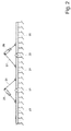
- Figur 2
- die Vorderansicht eines Grubbers mit großer Arbeitsbreite, der aus mehreren nebeneinander angeordneten und schwenkbar miteinander verbundenen Sektionen besteht
- An einem allradgeti-iebetien Arbeitsfahrzeug 1 ist über eine Anhängevorriclltung 2 ein als Grubber ausgeführtes Bodenbearbeitungsgerät 3 angehängt. Das Arbeitsfahrzeug 1 umfasst im Wesentlichen einen Fahrzeugrahmen 4, einen Antriebsmotor 5, eine Fahrerkabine 6 sowie eine Vorderachse 7 mit den Vorderrädern 8 und eine Hinterachse 9 mit den Hinterrädern 10. Die Anhängevorrichtung 2 besteht in ihrer Längsausdehnung aus einem winkelförmigen Rahmen, wobei sich ein Rahmenteil 11 oberhalb des Fahrzeugrahmens 4 erstreckt und das andere Rahmenteil 12 abwärts zurn Bodenbearbeitungsgerät 3 gerichtet ist. Am Arbeitsfahrzeug 1 ist die Anhängevorrichtung 2 an einer etwa mittig zwischen den Vorder und Hinterrädern 8, 10 an der Oberseite des Fahrxeugsrahmens 4 angeordneten Kugelgelenkkupplung 13 lösbar befestigt. Das abwärts gerichtete Rahmenteil 12 der Anhängevorrichtung 2 ist mit dem Tragrahmen 14 des Bodenbearbeitungsgerätes 3 über ein Gelenk 15 schwenkbar verbunden. Am Tragrahmen 14 sind unter anderem die einzelnen Werkzeuge 16 des Bodenbearbeitungsgerätes 3 befestigt Zwischen dem abwärts gerichteten Rahmenteil 12 und dem vorderen Bereich des Tragrahmens 14 ist oberhalb des Gelenkes 15 ein Hydraulikzylinder 17 gelenkig angeordnet Durch eine entsprechende Beaufschlagung des Hydraulikzylinders 17 werden die jeweils auf die Vorder- und Hinterräder 8,10 des Arbeitsfahrzeuges 12 oder auf die Werkzeuge 16 des Bodenbearbeitungsgerätes 3 wirkenden Kräfte geregelt.
Entsprechend der veränderbaren Stellkraft FS des Hydraulikzylinders 17 werden die auf die Werkzeuge 16 wirkenden vertikalen Kräfte FW sowie die auf die Vorder- und Hinterräder 8,10 einwirkenden Vertikalkräfte V1, V2 gesteuert und uber die Anhängevorrichtung 2 übertragen. Die Stellkraft Fs des Hydraulikzylinders 17 wird verringert, damit die Arbeitswerkzeuge 16 des Bodenbearbeitungsgerätes 3 durch das Eigengewicht des Bodenbearbeitungsgerätes 3 in den Boden eingezogen werden. Die Stellkraft FS des Hydraulikzylinders wird erhöht, damit das Eigengewicht des Bodebearbeitungsgerätes 3 zumindest teilweise über die Anhängevorrichtung 2 auf das Arbeitsfahrzeug 1 übertragen werden.
Die erforderliche Zugkraft Z des Arbeitsfahrzeuges 1 ist dabei abhängig von den jeweils auf die angetriebenen Vorder- und Hinterräder 8, 10 wirkenden Vertikalkräfte V1, V2, wobei mit steigenden Vertikalkräften V1, V2 die Zugkraft Z des Arbeitsfahrzeuges 1 zunimmt. Im vorderen Bereich des Tragrahmens 14 des Bodenbearbeitungsgerätes 3 ist ein Sensor 18 angeordnet, der den Höhenabstand HA des Tragrahmens 14 zum Feldboden 19 erfasst. Der Sensor 18 ist vorzugsweise als Radarsensor ausgeführt In Abhängigkeit vom Abstandssignal des Sensors 18 wird der Hydraulikzylinder 17 entsprechend beaufschlagt und damit die Arbeitstiefe AT der Werkzeuge 16 geregelt und auf dem Jeweils erforderlichen Wert gehalten. Am hinteren Ende des Tragrahmens 14 sind höheneinstellbare Stützräder 20 angeordnet, die in Abhängigkeit von dem vom Sensor 18 erfassten Höhenabstand HA eine zusätzliche Einstellung der Arbeitstiefe AT ermöglichen. - Auch bei Bodenbearbeitungsgeräten 3 mit einer großen Arbeitsbreite (Fig. 2) mit mehreren nebeneinander quer zur Fahrtrichtung und durch Gelenke 21,22 miteinander verbundenen Einzelrahmen 23, 24, 25 ist das Prinzip der erfindunssgemäßen Lösung anwendbar. Zwischen den Einzelrahmen 23, 24, 25 sind jeweils im Bereich oberhalb der Gelenke 21.22, an Halterungen 26, 27 Hydraulikzylinder 28, 29 angebracht. Die Steuerung und Beaufschlagung der Hydraulikzylinder 28, 29 und deren Wirkungsweise erfolgt in der gleichen Art bei der in der Fig. 1 beschriebenen Ausführung.
-
- 1
- Arbeitsfahrzeug
- 2
- Anhängevorrichtung
- 3
- Bodenbearbeitungsgerät
- 4
- Fahrzeugrahmen
- 5
- Antriebsmotor
- 6
- Fahrerkabine
- 7
- Vorderachse
- 8
- Vorderräder
- 9
- Hinterachse
- 10
- Hinterräder
- 11
- Rahmenteil
- 12
- Rahmenteil
- 13
- Kugelgelenkkupplung
- 14
- Tragrahmen
- 15
- Gelenk
- 16
- Werkzeug
- 17
- Hydraulikzylinder
- 18
- Sensor
- 19
- Feldboden
- 20
- Stützräder
- 21
- Gelenk
- 22
- Gelenk
- 23
- Einzelrahmen
- 24
- Einzelrahmen
- 25
- Einzelrahmen
- 26
- Halterung
- 27
- Halterung
- 28
- Hydraulikzylinder
- 29
- Hydraulikzylinder
- FS
- Stellkraft
- FW
- Werkzeugkräfte
- V1, V2
- Vertikalkräfte
- Z
- Zugkraft
- HA
- Höhenabstand
- AT
- Arbeitstiefe
Claims (11)
- Verfahren zur Regelung der Zugkraft eines allradgetriebenen Arbeitsfahrzeuges mit einem angehängten Bodenbearbeitungsgerät, insbesondere eines Grubbers, wobei das Arbeitsfahrzeug und das Bodenbearbeitungsgerät durch eine Anhängevorrichtung miteinander verbunden sind und die Arbeitstiefe der Werkzeuge des Bodenbearbeitungsgerätes im Feldboden einstellbar ist,
dadurch gekennzeichnet,
dass die Regelung der Größe der Zugkraft (Z) des Arbestsfahrzeuges (1) in Abhängigkeit von den an den Werkzeugen (16) des Bodenbearbeitungsgerätes (3) wirkenden vertikalen Kräften (FW) erfolgt - Vorrichtung zur Regelung der Zugkraft eines allradgetriebenen. Arbeitsfahrzeuges mit einem angehängten Bodenbearbeitungsgerät, insbesondere eines Grubbers, wobei das Arbeitsfahrzeug und das Bodenbearbeitungsgerät durch eine Anhängevorrichtung miteinander verbunden sind und die Arbeitstiefe der Werkzeuge des Bodenbearbeitungsgerätes im Feldboden einstellbar ist,
dadurch gekennzeichnet,
dass die Anhängevorrichtung (2) an einer etwa mittig zwischen den Vorder und Hinterrädern (8,10) an der Oberseite des Fahrzeugrahmens (4) des Arbeitsfahrzeuges (1) angeordneten Kugelgelerikkupplung (13) und über ein Gelenk (15) am Tragrahmen (14) des Bodenbearbeitungsgerätes (3) befestigt ist. - Vorrichtung nach Anspruch 2,
dadurch gekennzeichnet,
dass die Anhängevorrichtung (2) in ihrer Längsausdehnung aus einem winkelförmigen Rahmen besteht, wobei sich ein Rahmenteil (11) oberhalb des Fahrzeugrahmens (4) erstreckt und das andere Rahmenteil, (12) abwärts zum Bodenbearbeitungsgerät (3) gerichtet ist - Vorrichtung nach Anspruch 2 und 3,
dadurch gekennzeichnet,
dass im Bereich oberhalb des Gelenkes (15) zwischen dem abwärts gerichteten Rahmenteil (12) der Anhängevorrichtung (2) und dem Tragrahmen (14) des Bodenbearbeitungsgerätes (3) ein einstellbarer Hydraulikzylinder (17) gelenkig angeordnet und über die Signale eines Sensors (18) beaufschlagbar ist. - Vorrichtung nach Anspruch 4,
dadurch gekennzeichnet,
dass mit dem Hydraulikzylinder (17) die Arbeitstiefe (AT) der Werkzeuge (16) des Bodenbearbeitungsgerätes (3) einstellbar ist. - Vorrichtung nach Anspruch 4 bis 5,
dadurch gekennzeichnet,
dass der Hydraulikzylinder (17) eine veränderbare Stellkraft (FS) aufweist. - Vorrichtung nach Anspruch 6,
dadurch gekennzeichnet,
dass die Stellkraft (Fs) des Hydraulikzylinders (17) verringert wird, damit die Arbeitswerkzeuge (16) des Bodenbearbeitungsgerätes (3) durch das Eigengewicht des Bodenbearbeitungsgerätes (3) in den Boden eingezogen werden. - Vorrichtung nach Anspruch 6,
dadurch gekennzeichnet,
dass die Stellkraft (FS) des Hydraulikzylinders (17) vergrößert wird, damit das Eigengewicht des Bodenbearbeitungsgerätes (3) zumindest teilweise über die Anhängevorrichtung (2) auf das Arbeitsfahrzeug (1) übertragen werden. - Vorrichtung nach Anspruch 4,
dadurch gekennzeichnet,
dass der Sensor (18) im vorderen Bereich des Tragrahmens (14) angeordnet ist und die Abstandserfassung zwischen dem Tragrahmen (14) und dem Feldboden (19) ermöglicht. - Vorrichtung nach Anspruch 2 bis 10,
dadurch gekennzeichnet,
dass dem Bodenbearbeitungsgerät (3) im hinteren Bereich wenigstens ein höhenverstellbares Stützrad (20) zugeordnet ist, wobei mit dem Stützrad (20) die Arbeitstiefe (AT) der Werkzeuge (16) zusätzlich einstellbar ist - Vorrichtung nach den Ansprüchen 2 bis 11
dadurch gekennzeichnet,
dass das Bodenbearbeitungsgerät (3) aus mehreren gelenkig miteinander verbundenen Einzelrahmen (23, 24, 25) besteht wobei zwischen den Einzelrahmen (23, 24, 25) Hydraulikzylinder (28, 29) angelenkt sind,
Applications Claiming Priority (1)
| Application Number | Priority Date | Filing Date | Title |
|---|---|---|---|
| DE200610009571 DE102006009571A1 (de) | 2006-02-28 | 2006-02-28 | Verfahren und Vorrichtung zur Regelung der Zugkraft eines Arbeitsfahrzeuges |
Publications (2)
| Publication Number | Publication Date |
|---|---|
| EP1825734A1 true EP1825734A1 (de) | 2007-08-29 |
| EP1825734B1 EP1825734B1 (de) | 2014-06-11 |
Family
ID=38137493
Family Applications (1)
| Application Number | Title | Priority Date | Filing Date |
|---|---|---|---|
| EP20060126471 Active EP1825734B1 (de) | 2006-02-28 | 2006-12-19 | Verfahren und Vorrichtung zur Regelung der Zugkraft eines Arbeitsfahrzeuges |
Country Status (2)
| Country | Link |
|---|---|
| EP (1) | EP1825734B1 (de) |
| DE (1) | DE102006009571A1 (de) |
Cited By (3)
| Publication number | Priority date | Publication date | Assignee | Title |
|---|---|---|---|---|
| WO2013013917A1 (en) * | 2011-07-22 | 2013-01-31 | Agco International Gmbh | Tractor control system |
| WO2015192827A1 (de) * | 2014-06-19 | 2015-12-23 | Technische Universität Dresden | Bodenbearbeitungseinheit sowie bodenbearbeitungsverfahren zur konservierenden bodenbearbeitung |
| DE102015115696A1 (de) | 2015-09-17 | 2017-03-23 | Claas Selbstfahrende Erntemaschinen Gmbh | Anhängevorrichtung für eine landwirtschaftliche Maschinenanordnung |
Citations (7)
| Publication number | Priority date | Publication date | Assignee | Title |
|---|---|---|---|---|
| GB957544A (en) * | 1962-05-23 | 1964-05-06 | County Commercial Cars Ltd | Improvements in or relating to tractor trailer vehicles |
| DE1205328B (de) * | 1962-08-01 | 1965-11-18 | Massey Ferguson Inc | Anordnung zum Steuern des an einem Ackerschlepper angebrachten hydraulischen Krafthebers |
| US3275084A (en) * | 1964-01-31 | 1966-09-27 | Massey Ferguson Inc | Tractor hydraulic control system |
| US4848481A (en) * | 1985-02-21 | 1989-07-18 | Jacques Bidon | Tractor with hydraulic control system for preventing skidding |
| EP1068780A1 (de) * | 1999-07-13 | 2001-01-17 | Deere & Company | Verschwenkbarer Geräteanbau eines Kraftfahrzeugs |
| GB2361673A (en) * | 2000-04-25 | 2001-10-31 | Joseph Carroll | Agricultural machine or vehicle with rail mounted cabin |
| EP1175818A2 (de) * | 2000-07-22 | 2002-01-30 | Robert Bosch Gmbh | Vorrichtung zum Steuern der Arbeitstiefe eines Bodenbearbeitungsgerätes, insbesondere eines Pfluges |
-
2006
- 2006-02-28 DE DE200610009571 patent/DE102006009571A1/de not_active Withdrawn
- 2006-12-19 EP EP20060126471 patent/EP1825734B1/de active Active
Patent Citations (8)
| Publication number | Priority date | Publication date | Assignee | Title |
|---|---|---|---|---|
| GB957544A (en) * | 1962-05-23 | 1964-05-06 | County Commercial Cars Ltd | Improvements in or relating to tractor trailer vehicles |
| DE1205328B (de) * | 1962-08-01 | 1965-11-18 | Massey Ferguson Inc | Anordnung zum Steuern des an einem Ackerschlepper angebrachten hydraulischen Krafthebers |
| US3275084A (en) * | 1964-01-31 | 1966-09-27 | Massey Ferguson Inc | Tractor hydraulic control system |
| US4848481A (en) * | 1985-02-21 | 1989-07-18 | Jacques Bidon | Tractor with hydraulic control system for preventing skidding |
| EP1068780A1 (de) * | 1999-07-13 | 2001-01-17 | Deere & Company | Verschwenkbarer Geräteanbau eines Kraftfahrzeugs |
| DE19932612A1 (de) | 1999-07-13 | 2001-01-25 | Deere & Co | Verschwenkbarer Geräteanbau eines Kraftfahrzeugs |
| GB2361673A (en) * | 2000-04-25 | 2001-10-31 | Joseph Carroll | Agricultural machine or vehicle with rail mounted cabin |
| EP1175818A2 (de) * | 2000-07-22 | 2002-01-30 | Robert Bosch Gmbh | Vorrichtung zum Steuern der Arbeitstiefe eines Bodenbearbeitungsgerätes, insbesondere eines Pfluges |
Cited By (5)
| Publication number | Priority date | Publication date | Assignee | Title |
|---|---|---|---|---|
| WO2013013917A1 (en) * | 2011-07-22 | 2013-01-31 | Agco International Gmbh | Tractor control system |
| US9078391B2 (en) | 2011-07-22 | 2015-07-14 | Agco International Gmbh | Tractor control system |
| EP3643152A1 (de) * | 2011-07-22 | 2020-04-29 | AGCO International GmbH | Steuersystem für einen traktor |
| WO2015192827A1 (de) * | 2014-06-19 | 2015-12-23 | Technische Universität Dresden | Bodenbearbeitungseinheit sowie bodenbearbeitungsverfahren zur konservierenden bodenbearbeitung |
| DE102015115696A1 (de) | 2015-09-17 | 2017-03-23 | Claas Selbstfahrende Erntemaschinen Gmbh | Anhängevorrichtung für eine landwirtschaftliche Maschinenanordnung |
Also Published As
| Publication number | Publication date |
|---|---|
| EP1825734B1 (de) | 2014-06-11 |
| DE102006009571A1 (de) | 2007-09-06 |
Similar Documents
| Publication | Publication Date | Title |
|---|---|---|
| EP3026997B1 (de) | Bodenbearbeitungsgerät mit einrichtung zur rückverfestigung | |
| EP1116430B1 (de) | Dreipunktaufhängung für einen Traktor, Schlepper oder dergleichen | |
| DE102014104417B3 (de) | Bodenbearbeitungsgerät mit Striegel- oder Einebnungsvorrichtung | |
| DE19539427A1 (de) | Vielfachgerät für Mischkulturen | |
| DE102015000984A1 (de) | Bodenbearbeitungsgerät | |
| DE102019201337A1 (de) | Landwirtschaftliches Arbeitsgerät, Deichselvorrichtung und Zugfahrzeug-Arbeitsgerät-Kombination | |
| DE102011122537B4 (de) | Integriertes Bodenbearbeitungsgerät für Drehpflüge | |
| EP1093707A1 (de) | Selbstfahrendes landwirtschaftliches Fahrzeug | |
| DE3004576A1 (de) | Kombinatsgeraet zur bodenbearbeitung | |
| WO2016192973A1 (de) | Steueranordnung für eine zugmaschine, zugmaschine mit einer steueranordnung und verfahren für eine steueranordnung | |
| EP3000294B1 (de) | Dynamisch regelbare achslastverteilung für eine landwirtschaftliche arbeitsmaschine | |
| EP2289296B1 (de) | Aufsatteldrehpflug mit Traktionsverstärker | |
| DE102005040954A1 (de) | Vorrichtung zur Balastierung von landwirtschaftlichen Fahrzeugen | |
| EP1825734B1 (de) | Verfahren und Vorrichtung zur Regelung der Zugkraft eines Arbeitsfahrzeuges | |
| EP3011811B1 (de) | Pflug | |
| DE2754871A1 (de) | Landwirtschaftliche geraetekombination | |
| EP0795265B1 (de) | Anhängevorrichtung | |
| DE19954423A1 (de) | Landwirtschaftliche Bestellkombination mit günstiger Schwerpunktsverlagerung | |
| DE60216961T2 (de) | Zum anschluss eines werkzeugs geeigneter bodenverdichter | |
| DE2948900C2 (de) | Gerätekupplungsvorrichtung für einen Schlepper | |
| EP4124221B1 (de) | Landwirtschaftliche maschine und landwirtschaftliche maschinenkombination | |
| EP2074879B1 (de) | Selbstfahrendes Trägerfahrzeug | |
| DE3913659C1 (en) | Hinged chassis agricultural vehicle - has hydraulic steering system with actuators and adjusting cylinder | |
| DE102006046329A1 (de) | Arbeitsfahrzeug mit einer Kupplungsvorrichtung zum Anhängen eines Arbeitsgerätes | |
| EP3701779A1 (de) | Landwirtschaftliche arbeitsmaschine und verfahren zum betreiben einer landwirtschaftlichen arbeitsmaschine |
Legal Events
| Date | Code | Title | Description |
|---|---|---|---|
| PUAI | Public reference made under article 153(3) epc to a published international application that has entered the european phase |
Free format text: ORIGINAL CODE: 0009012 |
|
| AK | Designated contracting states |
Kind code of ref document: A1 Designated state(s): AT BE BG CH CY CZ DE DK EE ES FI FR GB GR HU IE IS IT LI LT LU LV MC NL PL PT RO SE SI SK TR |
|
| AX | Request for extension of the european patent |
Extension state: AL BA HR MK YU |
|
| 17P | Request for examination filed |
Effective date: 20080229 |
|
| 17Q | First examination report despatched |
Effective date: 20080404 |
|
| AKX | Designation fees paid |
Designated state(s): AT BE BG CH CY CZ DE DK EE ES FI FR GB GR HU IE IS IT LI LT LU LV MC NL PL PT RO SE SI SK TR |
|
| REG | Reference to a national code |
Ref country code: DE Ref legal event code: R079 Ref document number: 502006013794 Country of ref document: DE Free format text: PREVIOUS MAIN CLASS: A01B0051020000 Ipc: A01B0063112000 |
|
| GRAP | Despatch of communication of intention to grant a patent |
Free format text: ORIGINAL CODE: EPIDOSNIGR1 |
|
| RIC1 | Information provided on ipc code assigned before grant |
Ipc: A01B 63/112 20060101AFI20140109BHEP Ipc: A01B 67/00 20060101ALI20140109BHEP |
|
| INTG | Intention to grant announced |
Effective date: 20140207 |
|
| GRAS | Grant fee paid |
Free format text: ORIGINAL CODE: EPIDOSNIGR3 |
|
| GRAA | (expected) grant |
Free format text: ORIGINAL CODE: 0009210 |
|
| AK | Designated contracting states |
Kind code of ref document: B1 Designated state(s): AT BE BG CH CY CZ DE DK EE ES FI FR GB GR HU IE IS IT LI LT LU LV MC NL PL PT RO SE SI SK TR |
|
| REG | Reference to a national code |
Ref country code: GB Ref legal event code: FG4D Free format text: NOT ENGLISH |
|
| REG | Reference to a national code |
Ref country code: CH Ref legal event code: EP |
|
| REG | Reference to a national code |
Ref country code: IE Ref legal event code: FG4D Free format text: LANGUAGE OF EP DOCUMENT: GERMAN |
|
| REG | Reference to a national code |
Ref country code: AT Ref legal event code: REF Ref document number: 671729 Country of ref document: AT Kind code of ref document: T Effective date: 20140715 |
|
| REG | Reference to a national code |
Ref country code: DE Ref legal event code: R096 Ref document number: 502006013794 Country of ref document: DE Effective date: 20140724 |
|
| PG25 | Lapsed in a contracting state [announced via postgrant information from national office to epo] |
Ref country code: GR Free format text: LAPSE BECAUSE OF FAILURE TO SUBMIT A TRANSLATION OF THE DESCRIPTION OR TO PAY THE FEE WITHIN THE PRESCRIBED TIME-LIMIT Effective date: 20140912 Ref country code: LT Free format text: LAPSE BECAUSE OF FAILURE TO SUBMIT A TRANSLATION OF THE DESCRIPTION OR TO PAY THE FEE WITHIN THE PRESCRIBED TIME-LIMIT Effective date: 20140611 Ref country code: FI Free format text: LAPSE BECAUSE OF FAILURE TO SUBMIT A TRANSLATION OF THE DESCRIPTION OR TO PAY THE FEE WITHIN THE PRESCRIBED TIME-LIMIT Effective date: 20140611 |
|
| REG | Reference to a national code |
Ref country code: NL Ref legal event code: VDEP Effective date: 20140611 |
|
| REG | Reference to a national code |
Ref country code: LT Ref legal event code: MG4D |
|
| PG25 | Lapsed in a contracting state [announced via postgrant information from national office to epo] |
Ref country code: LV Free format text: LAPSE BECAUSE OF FAILURE TO SUBMIT A TRANSLATION OF THE DESCRIPTION OR TO PAY THE FEE WITHIN THE PRESCRIBED TIME-LIMIT Effective date: 20140611 Ref country code: SE Free format text: LAPSE BECAUSE OF FAILURE TO SUBMIT A TRANSLATION OF THE DESCRIPTION OR TO PAY THE FEE WITHIN THE PRESCRIBED TIME-LIMIT Effective date: 20140611 |
|
| PG25 | Lapsed in a contracting state [announced via postgrant information from national office to epo] |
Ref country code: SK Free format text: LAPSE BECAUSE OF FAILURE TO SUBMIT A TRANSLATION OF THE DESCRIPTION OR TO PAY THE FEE WITHIN THE PRESCRIBED TIME-LIMIT Effective date: 20140611 Ref country code: ES Free format text: LAPSE BECAUSE OF FAILURE TO SUBMIT A TRANSLATION OF THE DESCRIPTION OR TO PAY THE FEE WITHIN THE PRESCRIBED TIME-LIMIT Effective date: 20140611 Ref country code: RO Free format text: LAPSE BECAUSE OF FAILURE TO SUBMIT A TRANSLATION OF THE DESCRIPTION OR TO PAY THE FEE WITHIN THE PRESCRIBED TIME-LIMIT Effective date: 20140611 Ref country code: EE Free format text: LAPSE BECAUSE OF FAILURE TO SUBMIT A TRANSLATION OF THE DESCRIPTION OR TO PAY THE FEE WITHIN THE PRESCRIBED TIME-LIMIT Effective date: 20140611 Ref country code: PT Free format text: LAPSE BECAUSE OF FAILURE TO SUBMIT A TRANSLATION OF THE DESCRIPTION OR TO PAY THE FEE WITHIN THE PRESCRIBED TIME-LIMIT Effective date: 20141013 Ref country code: CZ Free format text: LAPSE BECAUSE OF FAILURE TO SUBMIT A TRANSLATION OF THE DESCRIPTION OR TO PAY THE FEE WITHIN THE PRESCRIBED TIME-LIMIT Effective date: 20140611 |
|
| PG25 | Lapsed in a contracting state [announced via postgrant information from national office to epo] |
Ref country code: IS Free format text: LAPSE BECAUSE OF FAILURE TO SUBMIT A TRANSLATION OF THE DESCRIPTION OR TO PAY THE FEE WITHIN THE PRESCRIBED TIME-LIMIT Effective date: 20141011 Ref country code: PL Free format text: LAPSE BECAUSE OF FAILURE TO SUBMIT A TRANSLATION OF THE DESCRIPTION OR TO PAY THE FEE WITHIN THE PRESCRIBED TIME-LIMIT Effective date: 20140611 Ref country code: NL Free format text: LAPSE BECAUSE OF FAILURE TO SUBMIT A TRANSLATION OF THE DESCRIPTION OR TO PAY THE FEE WITHIN THE PRESCRIBED TIME-LIMIT Effective date: 20140611 |
|
| REG | Reference to a national code |
Ref country code: DE Ref legal event code: R097 Ref document number: 502006013794 Country of ref document: DE |
|
| PLBE | No opposition filed within time limit |
Free format text: ORIGINAL CODE: 0009261 |
|
| STAA | Information on the status of an ep patent application or granted ep patent |
Free format text: STATUS: NO OPPOSITION FILED WITHIN TIME LIMIT |
|
| PG25 | Lapsed in a contracting state [announced via postgrant information from national office to epo] |
Ref country code: DK Free format text: LAPSE BECAUSE OF FAILURE TO SUBMIT A TRANSLATION OF THE DESCRIPTION OR TO PAY THE FEE WITHIN THE PRESCRIBED TIME-LIMIT Effective date: 20140611 Ref country code: IT Free format text: LAPSE BECAUSE OF FAILURE TO SUBMIT A TRANSLATION OF THE DESCRIPTION OR TO PAY THE FEE WITHIN THE PRESCRIBED TIME-LIMIT Effective date: 20140611 |
|
| 26N | No opposition filed |
Effective date: 20150312 |
|
| REG | Reference to a national code |
Ref country code: DE Ref legal event code: R097 Ref document number: 502006013794 Country of ref document: DE Effective date: 20150312 |
|
| PG25 | Lapsed in a contracting state [announced via postgrant information from national office to epo] |
Ref country code: BE Free format text: LAPSE BECAUSE OF NON-PAYMENT OF DUE FEES Effective date: 20141231 |
|
| PG25 | Lapsed in a contracting state [announced via postgrant information from national office to epo] |
Ref country code: SI Free format text: LAPSE BECAUSE OF FAILURE TO SUBMIT A TRANSLATION OF THE DESCRIPTION OR TO PAY THE FEE WITHIN THE PRESCRIBED TIME-LIMIT Effective date: 20140611 Ref country code: LU Free format text: LAPSE BECAUSE OF FAILURE TO SUBMIT A TRANSLATION OF THE DESCRIPTION OR TO PAY THE FEE WITHIN THE PRESCRIBED TIME-LIMIT Effective date: 20141219 |
|
| REG | Reference to a national code |
Ref country code: CH Ref legal event code: PL |
|
| REG | Reference to a national code |
Ref country code: IE Ref legal event code: MM4A |
|
| PG25 | Lapsed in a contracting state [announced via postgrant information from national office to epo] |
Ref country code: IE Free format text: LAPSE BECAUSE OF NON-PAYMENT OF DUE FEES Effective date: 20141219 Ref country code: LI Free format text: LAPSE BECAUSE OF NON-PAYMENT OF DUE FEES Effective date: 20141231 Ref country code: CH Free format text: LAPSE BECAUSE OF NON-PAYMENT OF DUE FEES Effective date: 20141231 |
|
| REG | Reference to a national code |
Ref country code: FR Ref legal event code: PLFP Year of fee payment: 10 |
|
| REG | Reference to a national code |
Ref country code: AT Ref legal event code: MM01 Ref document number: 671729 Country of ref document: AT Kind code of ref document: T Effective date: 20141219 |
|
| PG25 | Lapsed in a contracting state [announced via postgrant information from national office to epo] |
Ref country code: BG Free format text: LAPSE BECAUSE OF FAILURE TO SUBMIT A TRANSLATION OF THE DESCRIPTION OR TO PAY THE FEE WITHIN THE PRESCRIBED TIME-LIMIT Effective date: 20140611 Ref country code: AT Free format text: LAPSE BECAUSE OF NON-PAYMENT OF DUE FEES Effective date: 20141219 Ref country code: MC Free format text: LAPSE BECAUSE OF FAILURE TO SUBMIT A TRANSLATION OF THE DESCRIPTION OR TO PAY THE FEE WITHIN THE PRESCRIBED TIME-LIMIT Effective date: 20140611 |
|
| PG25 | Lapsed in a contracting state [announced via postgrant information from national office to epo] |
Ref country code: CY Free format text: LAPSE BECAUSE OF FAILURE TO SUBMIT A TRANSLATION OF THE DESCRIPTION OR TO PAY THE FEE WITHIN THE PRESCRIBED TIME-LIMIT Effective date: 20140611 |
|
| PG25 | Lapsed in a contracting state [announced via postgrant information from national office to epo] |
Ref country code: HU Free format text: LAPSE BECAUSE OF FAILURE TO SUBMIT A TRANSLATION OF THE DESCRIPTION OR TO PAY THE FEE WITHIN THE PRESCRIBED TIME-LIMIT; INVALID AB INITIO Effective date: 20061219 Ref country code: TR Free format text: LAPSE BECAUSE OF FAILURE TO SUBMIT A TRANSLATION OF THE DESCRIPTION OR TO PAY THE FEE WITHIN THE PRESCRIBED TIME-LIMIT Effective date: 20140611 |
|
| REG | Reference to a national code |
Ref country code: FR Ref legal event code: PLFP Year of fee payment: 11 |
|
| REG | Reference to a national code |
Ref country code: FR Ref legal event code: PLFP Year of fee payment: 12 |
|
| PGFP | Annual fee paid to national office [announced via postgrant information from national office to epo] |
Ref country code: GB Payment date: 20211221 Year of fee payment: 16 Ref country code: FR Payment date: 20211224 Year of fee payment: 16 |
|
| REG | Reference to a national code |
Ref country code: DE Ref legal event code: R084 Ref document number: 502006013794 Country of ref document: DE |
|
| P01 | Opt-out of the competence of the unified patent court (upc) registered |
Effective date: 20230515 |
|
| GBPC | Gb: european patent ceased through non-payment of renewal fee |
Effective date: 20221219 |
|
| PG25 | Lapsed in a contracting state [announced via postgrant information from national office to epo] |
Ref country code: GB Free format text: LAPSE BECAUSE OF NON-PAYMENT OF DUE FEES Effective date: 20221219 |
|
| PG25 | Lapsed in a contracting state [announced via postgrant information from national office to epo] |
Ref country code: FR Free format text: LAPSE BECAUSE OF NON-PAYMENT OF DUE FEES Effective date: 20221231 |
|
| PGFP | Annual fee paid to national office [announced via postgrant information from national office to epo] |
Ref country code: DE Payment date: 20251211 Year of fee payment: 20 |