EP1821358A1 - Fuel cell system and method for controlling the same - Google Patents
Fuel cell system and method for controlling the same Download PDFInfo
- Publication number
- EP1821358A1 EP1821358A1 EP05775106A EP05775106A EP1821358A1 EP 1821358 A1 EP1821358 A1 EP 1821358A1 EP 05775106 A EP05775106 A EP 05775106A EP 05775106 A EP05775106 A EP 05775106A EP 1821358 A1 EP1821358 A1 EP 1821358A1
- Authority
- EP
- European Patent Office
- Prior art keywords
- fuel
- aqueous
- amount
- fuel cell
- solution
- Prior art date
- Legal status (The legal status is an assumption and is not a legal conclusion. Google has not performed a legal analysis and makes no representation as to the accuracy of the status listed.)
- Withdrawn
Links
Images


Classifications
-
- H—ELECTRICITY
- H01—ELECTRIC ELEMENTS
- H01M—PROCESSES OR MEANS, e.g. BATTERIES, FOR THE DIRECT CONVERSION OF CHEMICAL ENERGY INTO ELECTRICAL ENERGY
- H01M8/00—Fuel cells; Manufacture thereof
- H01M8/04—Auxiliary arrangements, e.g. for control of pressure or for circulation of fluids
- H01M8/04298—Processes for controlling fuel cells or fuel cell systems
- H01M8/043—Processes for controlling fuel cells or fuel cell systems applied during specific periods
- H01M8/04302—Processes for controlling fuel cells or fuel cell systems applied during specific periods applied during start-up
-
- H—ELECTRICITY
- H01—ELECTRIC ELEMENTS
- H01M—PROCESSES OR MEANS, e.g. BATTERIES, FOR THE DIRECT CONVERSION OF CHEMICAL ENERGY INTO ELECTRICAL ENERGY
- H01M8/00—Fuel cells; Manufacture thereof
- H01M8/04—Auxiliary arrangements, e.g. for control of pressure or for circulation of fluids
- H01M8/04082—Arrangements for control of reactant parameters, e.g. pressure or concentration
- H01M8/04186—Arrangements for control of reactant parameters, e.g. pressure or concentration of liquid-charged or electrolyte-charged reactants
-
- H—ELECTRICITY
- H01—ELECTRIC ELEMENTS
- H01M—PROCESSES OR MEANS, e.g. BATTERIES, FOR THE DIRECT CONVERSION OF CHEMICAL ENERGY INTO ELECTRICAL ENERGY
- H01M8/00—Fuel cells; Manufacture thereof
- H01M8/04—Auxiliary arrangements, e.g. for control of pressure or for circulation of fluids
- H01M8/04223—Auxiliary arrangements, e.g. for control of pressure or for circulation of fluids during start-up or shut-down; Depolarisation or activation, e.g. purging; Means for short-circuiting defective fuel cells
- H01M8/04225—Auxiliary arrangements, e.g. for control of pressure or for circulation of fluids during start-up or shut-down; Depolarisation or activation, e.g. purging; Means for short-circuiting defective fuel cells during start-up
-
- H—ELECTRICITY
- H01—ELECTRIC ELEMENTS
- H01M—PROCESSES OR MEANS, e.g. BATTERIES, FOR THE DIRECT CONVERSION OF CHEMICAL ENERGY INTO ELECTRICAL ENERGY
- H01M8/00—Fuel cells; Manufacture thereof
- H01M8/10—Fuel cells with solid electrolytes
- H01M8/1009—Fuel cells with solid electrolytes with one of the reactants being liquid, solid or liquid-charged
- H01M8/1011—Direct alcohol fuel cells [DAFC], e.g. direct methanol fuel cells [DMFC]
-
- Y—GENERAL TAGGING OF NEW TECHNOLOGICAL DEVELOPMENTS; GENERAL TAGGING OF CROSS-SECTIONAL TECHNOLOGIES SPANNING OVER SEVERAL SECTIONS OF THE IPC; TECHNICAL SUBJECTS COVERED BY FORMER USPC CROSS-REFERENCE ART COLLECTIONS [XRACs] AND DIGESTS
- Y02—TECHNOLOGIES OR APPLICATIONS FOR MITIGATION OR ADAPTATION AGAINST CLIMATE CHANGE
- Y02E—REDUCTION OF GREENHOUSE GAS [GHG] EMISSIONS, RELATED TO ENERGY GENERATION, TRANSMISSION OR DISTRIBUTION
- Y02E60/00—Enabling technologies; Technologies with a potential or indirect contribution to GHG emissions mitigation
- Y02E60/30—Hydrogen technology
- Y02E60/50—Fuel cells
Definitions
- the present invention relates to fuel cell systems and control methods of the same. More specifically, the present invention relates to a fuel cell system which provides circular supply of aqueous fuel solution to an anode of a fuel cell, and a method of controlling the fuel cell system.
- Patent Document 1 discloses a technique that temperature raising means is provided between a fuel storing portion and a cell stack, and part of aqueous methanol solution in the fuel storing portion is supplied to the temperature raising means at the time of start-up, thereby increasing the temperature of the aqueous methanol solution.
- the temperature raising means includes a platinum catalyst, and generates heat through a chemical reaction process involving oxidization when the aqueous methanol solution is brought in contact with the platinum catalyst and air.
- Patent Document 1 JPA 2004-55474
- Patent Document 1 enables to quicken temperature rise of the aqueous methanol solution which is to be supplied to the fuel cell; however, part of the aqueous methanol solution is oxidized, which reduces methanol utilization efficiency.
- a primary object of the present invention is to provide a fuel cell system and a control method of the fuel cell system capable of shortening the temperature rise time in which aqueous fuel solution which is to be supplied to the fuel cell reaches a predetermined temperature, without decreasing fuel utilization efficiency.
- a fuel cell system which includes: a fuel cell having an anode; fuel supplying means for circular supply of aqueous fuel solution to the anode of the fuel cell; and aqueous-solution-amount adjusting means for setting an amount of aqueous fuel solution in the fuel supplying means for a start-up to an amount smaller than for a normal operation.
- a method of controlling a fuel cell system which includes: a fuel cell having an anode; and fuel supplying means for circular supply of aqueous fuel solution to the anode of the fuel cell.
- the method includes a step of setting an amount of aqueous fuel solution in the fuel supplying means for a start-up to an amount smaller than for a normal operation.
- the amount of aqueous fuel solution in the fuel supplying means when the fuel cell system is started is smaller than the amount for normal operation.
- the amount of aqueous fuel solution in circulation during the start-up operation of the fuel cell system is smaller than the amount during the normal operation.
- the fuel supplying means includes an aqueous solution tank for storing the aqueous fuel solution, and the aqueous-solution-amount adjusting means adjusts an amount of aqueous fuel solution in the aqueous solution tank.
- the adjustment is necessary only to the amount of aqueous fuel solution in the aqueous solution tank. Therefore, the adjustment to the amount of aqueous fuel solution in the fuel supplying means becomes easy.
- the fuel cell system further includes a tank separately from the aqueous solution tank, for storing the aqueous fuel solution, and the aqueous-solution-amount adjusting means is capable of moving aqueous fuel solution from the aqueous solution tank to the separate tank.
- the amount of aqueous fuel solution in the fuel supplying means can be adjusted easily by only moving the aqueous fuel solution from the aqueous solution tank to the separate tank.
- the fuel cell system further includes a water tank for storing liquid discharged from the fuel cell, and the aqueous-solution-amount adjusting means is capable of moving aqueous fuel solution from the fuel supplying means to the water tank.
- the aqueous-solution-amount adjusting means is capable of moving aqueous fuel solution from the fuel supplying means to the water tank. In this case, an extra amount of aqueous fuel solution in the fuel supplying means may simply be moved to the water tank, so there is no need to provide other separate tanks.
- the fuel cell system further includes a relief tank for receiving the aqueous fuel solution from the fuel supplying means, and the aqueous-solution-amount adjusting means is capable of moving aqueous fuel solution from the fuel supplying means to the relief tank.
- the aqueous-solution-amount adjusting means is capable of moving aqueous fuel solution from the fuel supplying means to the relief tank.
- the fuel cell system further includes temperature detecting means for detecting a temperature of the fuel cell, and the aqueous-solution-amount adjusting means adjusts the amount of aqueous fuel solution in the fuel supplying means based on the temperature of the fuel cell detected by the temperature detecting means.
- the aqueous-solution-amount adjusting means adjusts the amount of aqueous fuel solution in the fuel supplying means based on the temperature of the fuel cell detected by the temperature detecting means.
- there is no need for excessively decreasing the amount of aqueous fuel solution and if a pump is used to control the amount of the liquid, drive time of the pump can be optimized and power consumption can be decreased.
- the fuel cell system further includes: a secondary battery electrically connected with the fuel cell; and amount-of-charge detection means for detecting an amount of charge in the secondary battery.
- the aqueous-solution-amount adjusting means adjusts the amount of aqueous fuel solution in the fuel supplying means in accordance with the amount of charge detected by the amount-of-charge detecting means.
- the aqueous-solution-amount adjusting means increases the amount of aqueous fuel solution in the fuel supplying means to a predetermined amount for the normal operation after the start-up operation.
- the temperature increase is accelerated during the start-up operation due to the decreased amount of the aqueous fuel solution whereas during the normal operation after the predetermined temperature has been attained, the amount of aqueous fuel solution is increased to a predetermined amount, which provides sufficient thermal capacity and stabilizes the system temperature, the concentration of aqueous fuel solution, etc.
- the fuel cell system further includes temperature detecting means for detecting a temperature of the fuel cell, and the aqueous-solution-amount adjusting means increases the amount of aqueous fuel solution in the fuel supplying means in accordance with the temperature of the fuel cell detected by the temperature detecting means.
- the amount of aqueous fuel solution in the fuel supplying means is increased gradually in accordance with the fuel cell temperature. Therefore, it becomes possible to bring the amount of aqueous fuel solution back to a predetermined amount without sacrificing the temperature stability of the fuel cell.
- the fuel cell system further includes temperature detecting means for detecting a temperature of the fuel cell, and the aqueous-solution-amount adjusting means increases the amount of aqueous fuel solution in the fuel supplying means when the temperature of the fuel cell detected by the temperature detecting means has reached a predetermined temperature, in such a way that the temperature of the fuel cell will stay at the predetermined temperature.
- the amount of aqueous fuel solution in the fuel supplying means is increased so that the fuel cell temperature will be kept at a predetermined temperature. Therefore, it is possible to bring the amount of aqueous fuel solution back to a predetermined amount without sacrificing the temperature stability of the fuel cell.
- the fuel cell system further includes temperature detecting means for detecting a temperature of the fuel cell, and the aqueous-solution-amount adjusting means increases the amount of aqueous fuel solution in the fuel supplying means to the predetermined amount when the temperature of the fuel cell detected by the temperature detecting means has reached a predetermined temperature.
- Fuel cell systems for transportation equipment must be smaller than those for stationary use, the capacity of the secondary battery for example is limited, and the system must be able to increase the temperature of aqueous fuel solution quickly at the time of start-up in order to shift to normal operation in a short time.
- the present invention is suitable for use in transportation equipment.
- the expression that "circular supply" of the aqueous fuel solution to the anode in the fuel cell means that aqueous fuel solution is supplied to the anode in the fuel cell together with aqueous fuel solution which was discharged from the anode in the fuel cell.
- start-up of the fuel cell system means a period of time which begins when the fuel cell system's main switch is turned ON, and continues to a time when the system starts its normal operation.
- normal operation of the fuel cell system means a state of consistent power generation, e.g. a state of operation where the temperature difference between a fuel cell temperature and a fuel cell target temperature which is set by a normal amount of aqueous solution is within 10°C.
- a fuel cell system 10 as an embodiment of the present invention is a direct methanol fuel cell system.
- Direct methanol fuel cell systems do not require a reformer and so can be utilized suitably in equipment which requires portability, as well as in equipment in which size reduction is desirable.
- the fuel cell system 10 is used on a motorbike as an example of transportation equipment. Note, however, that the motorbike will be represented only by a vehicle frame 200 as shown in Fig. 2. Note also that as in Fig. 2, the left side of the diagram represents the front of the vehicle while the right side represents the rear of the vehicle. Further, the fuel cell system 10 is disposed along the vehicle frame 200.
- the fuel cell system 10 includes a fuel cell 12.
- the fuel cell 12 is configured as a fuel cell stack composed of a plurality of direct methanol fuel cells connected in series (into a layer), each including an electrolyte 12a, an anode (fuel electrode) 12b and a cathode (air electrode) 12c which sandwich the electrolyte 12a in between.
- the fuel cell system 10 includes a fuel tank 14 which stores highly concentrated methanol fuel (aqueous solution containing approximately 50 weight percent of methanol) F.
- the fuel tank 14 is connected, via a fuel supply pipe 16, with an aqueous solution tank 18 which stores aqueous methanol solution S which serves as aqueous fuel solution.
- the fuel supply pipe 16 is provided with a fuel pump 20.
- the fuel pump 20 supplies the aqueous solution tank 18 with the methanol fuel F from the fuel tank 14.
- the fuel tank 14 is provided with a level sensor 15 for detecting the level of methanol fuel F in the fuel tank 14.
- the aqueous solution tank 18 is provided with a level sensor 22 for detecting the level of aqueous methanol solution S in the aqueous solution tank 18.
- the level sensors 15, 22 are each provided by a float-type sensor for example.
- the level of fluid in the tank can be detected as a float (not illustrated) moves up and down in the tank following the level of the fluid. In other words, the amount of fluid (amount of water) in the tank can be detected based on the position of the float which moves. The same applies to a level sensor 54 to be described later.
- the aqueous solution tank 18 is connected, via an aqueous solution pipe 24, with the anode 12b of the fuel cell 12.
- the aqueous solution pipe 24 is provided with an aqueous solution pump 26, a radiator 28 functioning as a heat exchanger, and an aqueous solution filter 30, in this order from the upstream side.
- a cooling fan 32 is provided near the radiator 28 in order to cool the radiator 28.
- the aqueous methanol solution S in the aqueous solution tank 18 is pumped by the aqueous solution pump 26 toward the anode 12b, cooled by the radiator 28 as necessary, and purified by the aqueous solution filter 30 before being supplied to the anode 12b.
- the cathode 12c in the fuel cell 12 is connected with an air pump 34 via an air pipe 36.
- the air pipe 36 is provided with an air filter 38.
- the anode 12b and the aqueous solution tank 18 are connected with each other via a pipe 40, so unused aqueous methanol solution and produced carbon dioxide discharged from the anode 12b are supplied to the aqueous solution tank 18.
- fuel supplying means 41 includes the aqueous solution tank 18, the aqueous solution pipe 24, the aqueous solution pump 26, the radiator 28, the aqueous solution filter 30, the cooling fan 32 and the pipe 40.
- the fuel supplying means 41 provides circular supply of the aqueous methanol solution S to the anode 12b in the fuel cell 12.
- the cathode 12c is connected with the water tank 44 via a pipe 42.
- the pipe 42 is provided with a radiator 46 which functions as a gas-liquid separator.
- a cooling fan 48 is disposed near the radiator 46 in order to cool the radiator 46.
- Exhaust containing water (water and water vapor) which is discharged from the cathode 12c is supplied to the water tank 44 via the pipe 42.
- An air pump 34 is driven to promote introduction of the exhaust into the water tank 44.
- aqueous solution tank 18 and the water tank 44 are connected with each other via a CO 2 vent pipe 50.
- the CO 2 vent pipe 50 is provided with a methanol trap 52 in order to separate aqueous methanol solution S.
- the carbon dioxide discharged from the aqueous solution tank 18 is thus supplied to the water tank 44.
- the water tank 44 is provided with a level sensor 54, which detects the level of water in the water tank 44.
- the water tank 44 is provided with an exhaust gas pipe 56.
- the exhaust gas pipe 56 discharges carbon dioxide and the exhaust from the cathode 12c.
- the water tank 44 thus stores water which is produced by the electrochemical reaction, and a small amount of methanol carried as a result of crossover, in the form of liquid.
- the water tank 44 is connected with the aqueous solution tank 18 via a water recycling pipe 58.
- the water recycling pipe 58 is provided with a water pump 60.
- the water pump 60 is capable of pumping the aqueous solution and water in Direction A or Direction B selectively. By switching the pumping direction of the water pump 60 depending on the situation of the aqueous solution tank 18, the aqueous solution from the water tank 44 is sent either to the aqueous solution tank 18 (Direction indicated by Arrow A) or vice versa (Direction indicated by Arrow B).
- the water recycling pipe 58 has an end extended into the aqueous solution tank 18 so as to submerge into the aqueous solution.
- flow of the aqueous methanol solution S can be branched off a circular supply route for temporary storage in a separate storage space (tank), so it is easy to reduce the amount of aqueous solution in circulation.
- a bypass pipe 62 is formed between the radiator 28 and the aqueous solution filter 30.
- the bypass pipe 62 is provided with a concentration sensor 64 which detects the concentration of aqueous methanol solution S.
- a temperature sensor 66 which detects the temperature of fuel cell 12 is attached to the fuel cell 12.
- An ambient temperature sensor 68 which detects the ambient temperature is provided near the air pump 34.
- the temperature of the fuel cell 12 detected by the temperature sensor 66 is regarded as the temperature of aqueous methanol solution S in circulation.
- the temperature of the cell stack 12 itself may be detected as the temperature of the fuel cell 12, and still another alternative is to detect the temperature of the exhaust from the cathode 12c.
- the fuel cell system 10 includes a control circuit 70.
- the control circuit 70 includes: a CPU 72 serving as control means which performs necessary arithmetic operations and provides control over the operation of the fuel cell system 10; a clock circuit 74 which provides the CPU 72 with clock signals; a memory 76 which may be provided by an EEPROM for example for storing programs and data for controlling the fuel cell system 10, calculation data, etc; a reset IC 78 which prevents the fuel cell system 10 from faulty operations; an interface circuit 82 for connection with external devices; a voltage detection circuit 84 for detecting the voltage in an electric circuit 82 which connects the fuel cell 12 with a motor 202 that drives the motorbike; an electric current detection circuit 86 for detecting the electric current flowing in the electric circuit 82; an ON/OFF circuit 88 which opens and closes the electric circuit 82; a voltage protection circuit 90 which prevents over voltage in the electric circuit 82; a diode 92 provided in the electric circuit 82; and a power source circuit 94 which supplies
- the CPU 72 is supplied with detection signals from the concentration sensor 64, the temperature sensor 66 and the ambient temperature sensor 68, as well as detection signals from a roll-over switch 96 which detects whether or not the vehicle is rolled over, and signals from an input unit 98 for settings and data input. Further, the CPU 72 is supplied with detection signals from the level sensors 15, 22 and 54.
- the CPU 72 provides control on such components as the fuel pump 20, the aqueous solution pump 26, the air pump 34, the heat exchanger cooling fan 32, the gas-liquid separator cooling fan 48, and the water pump 60. Also, the CPU 72 controls a display 100 which displays various kinds of information for the rider of the motorbike.
- the fuel cell 12 is connected with a secondary battery 102 and an electric charge detector 103 which detects the amount of charge (remaining power) in the secondary battery 102.
- the secondary battery 102 and the electric charge detector 103 which are connected with each other in series have a parallel connection with the motor 202.
- the secondary battery 102 which provides power to supplement the output from the fuel cell 12, is charged by the fuel cell 12 with electric energy, and gives electric energy to the motor 202 and the other components, by discharging.
- the motor 202 is connected with a meter 204 for various measurements on the motor 202. Data and status information about the motor 202 measured by the meter 204 are supplied to the CPU 72 via an interface circuit 104.
- the memory 76 stores table data as shown in Fig. 5(a) which relates the temperature of the fuel cell 12 to a target amount of aqueous solution, programs for executing operations as shown in Fig. 6 through Fig. 8, and other information.
- Fig. 5(b) is a graph which shows the relationship between the temperature of the fuel cell 12 and the target amount of aqueous solution.
- target amount of aqueous solution is a target amount of aqueous methanol solution S to be stored in the aqueous solution tank 18.
- the target amount of aqueous solution is set higher as the fuel cell temperature becomes higher.
- the target amount of aqueous solution is set smaller as the fuel cell temperature becomes lower.
- the temperature is low, a large amount of aqueous solution is moved to the other tank, enabling to increase the temperature rising speed at an early period of start up.
- a greater amount of aqueous methanol solution S in the aqueous solution tank 18 leads to more stable temperature of the aqueous methanol solution S which is circulating in the fuel cell 12 and the fuel supplying means 41, and to smaller fluctuation in the concentration of methanol in the aqueous solution. For this reason, a greater amount of aqueous methanol solution is generally more preferable in operating the fuel cell system 10.
- aqueous-solution-amount adjusting means includes the water recycling pipe 58, the water pump 60 and the control circuit 70.
- aqueous methanol solution S which is stored in the aqueous solution tank 18 and has a desired level of concentration is pumped by the aqueous solution pump 26 toward the fuel cell 12.
- the solution is cooled as necessary by the radiator 28, purified by the aqueous solution filter 30, and then supplied to the anode 12b.
- air which contains oxygen is pumped by the air pump 34 toward the fuel cell 12. The air is purified by the air filter 38 and then supplied to the cathode 12c.
- methanol and water in the aqueous methanol solution S react electro-chemically with each other to produce carbon dioxide and hydrogen ions.
- the hydrogen ions move through the electrolyte 12a to the cathode 12c, where the hydrogen ions react electro-chemically with oxygen in the air which is supplied to the cathode 12c, to produce water (water vapor) and electric energy.
- Carbon dioxide which occurred on the anode 12b in the fuel cell 12 flows through the pipe 40, the aqueous solution tank 18 and the CO 2 vent pipe 50 to the water tank 44, and then it is discharged from the exhaust gas pipe 56.
- water crossover is a phenomenon in which a few mols of water moves to the cathode 12c, accompanying the hydrogen ions which occur at the anode 12b and are moving to the cathode 12c.
- methanol crossover is a phenomenon in which methanol moves to the cathode 12c, accompanying the hydrogen ions which move to the cathode 12c. Methanol which has moved to the cathode 12c reacts with air supplied from the air pump 34, thereby decomposed into water and carbon dioxide.
- Water (liquid) which was collected in the water tank 44 is recycled appropriately by the water pump 60, through the water recycling pipe 58 to the aqueous solution tank 18, where the water is used for the aqueous methanol solution S.
- Step S1 when an unillustrated main switch is turned ON, a "main switch ON" signal is inputted to the CPU 72 (Step S1), and the system waits for a rise of power source voltage.
- the electric charge detector 103 detects the amount of charge (remaining power) in the secondary battery 102 (Step S3) . Based on the detected amount of charge in the secondary battery 102, the system checks if the water pump 60 is drivable or not (Step S5).
- the system determines that it can drive the water pump 60. Then, the temperature sensor 66 detects the temperature of the fuel cell 12 (Step S7).
- the system then makes reference to the table data shown in Fig. 5, to select/determine a target amount of aqueous solution corresponding to the temperature detected in Step S7 (Step S9) .
- the level sensor 22 detects the current amount of aqueous methanol solution S in the aqueous solution tank 18 (Step S11).
- the system checks if the detected amount of aqueous solution is greater than the target amount of aqueous solution which was found on the basis of the fuel cell temperature, i.e. the temperature of aqueous fuel solution (Step S13).
- Step S13 the power in the secondary battery 102 is used to drive the water pump 60, whereby aqueous methanol solution S in the aqueous solution tank 18 is sent through the water recycling pipe 58 to the water tank 44 (in the direction B as in Fig. 1) (Step S15).
- the system then checks if the amount of aqueous solution in the aqueous solution tank 18 has reached the target amount of aqueous solution (Step S17).
- Step S19 finds that a predetermined amount of time has passed.
- Step S17 checks again if the target amount of aqueous solution has been reached. The pumping of aqueous methanol solution S is continued until S17 finds that the amount of aqueous solution in the aqueous solution tank 18 has reached the target amount of aqueous solution. Once Step S17 gives "YES", the water pump 60 is stopped (Step S21).
- Step S13 finds that the amount of aqueous solution in the aqueous solution tank 18 is not greater than the target amount of aqueous solution
- the system checks if the amount of aqueous solution is smaller than the target amount of aqueous solution (Step S23). If the amount of aqueous solution is smaller than the target amount of aqueous solution, power in the secondary battery 102 is used to drive the water pump 60, to send water or aqueous solution in the water tank 44 to the aqueous solution tank 18 through the water recycling pipe 58 (in the direction A as in Fig. 1) (Step S25).
- the amount of aqueous solution in the aqueous solution tank 18 can be smaller than the target amount of aqueous solution when, for example, a long time has passed since power generating operation was stopped and crossover has caused aqueous solution to leak out of the aqueous solution tank 18.
- Step S27 the system checks if the above-described adjustment on the amount of aqueous solution has brought the amount of the aqueous solution in the aqueous solution tank 18 to the target amount of aqueous solution. If the amount of aqueous solution in the aqueous solution tank 18 has not yet reached the target amount of aqueous solution, pumping of water or aqueous solution is continued until Step S29 finds a predetermined amount of time has passed. After the lapse of the predetermined amount of time, Step S27 checks again, if the amount has reached the target amount of aqueous solution.
- Step S27 finds the amount of aqueous solution in the aqueous solution tank 18 has reached the target amount of aqueous solution.
- Step S23 gives "NO", i.e. if the amount of aqueous solution in the aqueous solution tank 18 is equal to the target amount of aqueous solution, the system proceeds directly to Step S21.
- Step S30 adjustment is made so that the aqueous solution in the aqueous solution tank 18 has a desired concentration.
- the concentration of aqueous solution is detected by, for example, a concentration sensor (not illustrated) provided in the aqueous solution tank 18. If the concentration of the aqueous solution is lower than the desired value, methanol fuel is added from the fuel tank 14 whereas water or aqueous solution is added from the water tank 44 if the concentration is higher than the desired value.
- Step S31 system components such as the fuel pump 20, the aqueous solution pump 26, the air pump 34, the heat-exchanger cooling fan 32, the gas-liquid-separator cooling fan 48 and the water pump 60 are driven to generate power (Step S31).
- Step S5 determines in Step S5 that it is impossible to drive the water pump 60.
- the water pump 60 is not driven to protect the fuel cell system 10 from shutting down, but a different step is performed (Step S33), to proceed to Step S31 and begin power generation.
- Fig. 7 describe an example of main operation of the fuel cell system 10 after power generation has been started.
- the amount of aqueous solution in the aqueous solution tank 18 is brought back to a predetermined level by gradually increasing the amount in accordance with temperature increase in the fuel cell 12.
- the temperature sensor 66 detects the temperature of the fuel cell 12 (Step S51).
- the system makes reference to the table data shown in Fig. 5, to select/determine a target amount of aqueous solution which corresponds to the detected temperature (Step S53).
- the level sensor 22 detects the current amount of aqueous methanol solution S in the aqueous solution tank 18 (Step S55).
- the system checks if the detected amount of aqueous solution is not smaller than the target amount of aqueous solution (Step S57).
- Step S59 If the detected amount of aqueous solution is smaller than the target amount of aqueous solution, the water pump 60 is driven, whereby water or aqueous solution in the water tank 44 is sent to the aqueous solution tank 18 via the water recycling pipe 58 (in the direction A as in Fig. 1) (Step S59).
- the system checks if the amount of aqueous solution in the aqueous solution tank 18 has reached the target amount of aqueous solution (Step S61). If the amount of aqueous solution in the aqueous solution tank 18 has not yet reached the target amount of aqueous solution, pumping of water or aqueous solution is continued until Step S63 finds that a predetermined amount of time has passed.
- Step S61 checks again if the target amount of aqueous solution has been reached. The above-described pumping is continued until Step S61 finds that the amount of aqueous solution in the aqueous solution tank 18 has reached the target amount of aqueous solution. Once Step S61 gives "YES”, the water pump 60 is stopped (Step S65). Thereafter, adjustment is made so that the concentration of aqueous solution in the aqueous solution tank 18 is desirable (Step S66).
- Step S67 the system checks if the aqueous solution tank 18 is full, i.e. if the amount of liquid is for normal operation (which is 3L in the present embodiment) (Step S67). If the aqueous solution tank 18 is full, normal operation is commenced. If the aqueous solution tank 18 is not full, the system waits until a predetermined amount of time has passed (Step S69: YES), and then brings the process back to Step S51, where the above-described cycle is repeated until the aqueous solution tank 18 becomes full.
- the amount of aqueous methanol solution S which is in circulation at the time of system start up is smaller than the amount during the normal operation, whereby it becomes possible to decrease thermal capacity of the aqueous methanol solution S which is in circular supply to the fuel cell 12. Therefore, it becomes possible to shorten the time required for heating the aqueous methanol solution S to a predetermined temperature (65°C, for example), enabling to increase the amount of generated power quickly after the start up. Further, since heating is not provided by oxidization of the aqueous methanol solution S, fuel utilization efficiency does not decrease.
- the amount of aqueous methanol solution S in the fuel supplying means 41 at an early stage is adjusted on the basis of the temperature of the fuel cell 12, whereby it becomes possible to increase the temperature of aqueous methanol solution S quickly while keeping temperature stability of the fuel cell 12. Further, there is no need for excessively decreasing the amount of aqueous methanol solution S, drive time of the water pump 60 can be optimized, and power consumption can be decreased.
- the amount of aqueous methanol solution S is at a predetermined level, i.e. the aqueous solution tank 18 is full. This provides sufficient thermal capacity and stabilizes the system temperature, the concentration of aqueous methanol solution S, etc.
- the amount of aqueous methanol solution S in the fuel supplying means 41 is set in a stepped manner in accordance with the temperature of the fuel cell 12 and the amount is increased gradually. Therefore, it is possible to bring the amount of aqueous methanol solution S back to a predetermined amount without sacrificing the temperature stability of the fuel cell 12.
- Fig. 8 describe another example of the main operation after the fuel cell system 10 has started power generation.
- the fuel cell temperature is increased to a predetermined temperature, and then the amount of aqueous solution is brought back to a predetermined amount while maintaining the temperature stably.
- the temperature sensor 66 detects the temperature of the fuel cell 12 (Step S101) .
- the system checks if the temperature of the fuel cell 12 has reached a predetermined temperature (65°C for example) (Step S103). If the temperature of the fuel cell 12 has not reached the predetermined temperature, the system waits until a predetermined amount of time has passed (Step S105: YES), and then goes back to Step S101 again, to repeat the above-described cycle until the predetermined temperature is reached.
- Step S103 finds that the temperature of the fuel cell 12 has reached the predetermined temperature, the system checks if the aqueous solution tank 18 is full or not (Step S107) .
- Step S109 the system checks if the temperature of the fuel cell 12 is not lower than a predetermined temperature (65°C for example) (Step S109). If the temperature of the fuel cell 12 is lower than the predetermined temperature, the system waits until a predetermined amount of time has passed (Step S111: YES), and then goes back to Step S107 again. If the aqueous solution tank 18 is not full (Step S107: NO) and the temperature of the fuel cell 12 is not lower than the predetermined temperature (Step S109: YES), the water pump 60 is driven to send water or aqueous solution from the water tank 44 to the aqueous solution tank 18 via the water recycling pipe 58 (Step S113).
- a predetermined temperature 65°C for example
- Step S115 the system checks if the temperature of the fuel cell 12 is not lower than a predetermined temperature (65°C for example) (Step S115). If the temperature of the fuel cell 12 is not lower than the predetermined temperature, the system waits until a predetermined amount of time has passed (Step S117: YES), and then goes back again to Step S115 again. In other words, water or aqueous solution is pumped until the temperature of the fuel cell 12 goes down below a predetermined temperature (65°C for example). In this way the amount of aqueous solution in the aqueous solution tank 18 is increased.
- a predetermined temperature 65°C for example
- Step S119 the water pump 60 is stopped (Step S119), adjustment is made so that the concentration of the aqueous solution in the aqueous solution tank 18 is desirable (Step S120), and the program goes back to Step S107, where the above-described cycle of process is repeated until the aqueous solution tank 18 becomes full. Once the aqueous solution tank 18 is full, the system proceeds to normal operation.
- the amount of aqueous methanol solution S in the fuel supplying means 41 is increased in such a way that the temperature of the fuel cell 12 stays at a predetermined level. Therefore, it is possible to bring the amount of aqueous methanol solution S back to a predetermined amount without impairing temperature stability of the fuel cell 12.
- the amount of aqueous solution in the aqueous solution tank 18 may be increased to the full level (the amount for the normal operation) in a single step once the temperature of the fuel cell 12 has reached a predetermined level after the fuel cell system 10 started power generation. This enables to shift to the normal operation quickly.
- the memory 76 may store table data as shown in Fig. 9(a).
- the data relates the amount of charge in the secondary battery 102 to the target amount of aqueous solution for the system to set an initial amount of aqueous methanol solution S in the aqueous solution tank 18 in accordance with the amount of charge in the secondary battery 102.
- the fuel cell 12 must be heated to a predetermined temperature (65°C approx.) more quickly if the amount of charge in the secondary battery 102 is smaller. Therefore, the system sets the amount of aqueous solution in the aqueous solution tank 18 to a smaller amount if the amount of charge is smaller.
- Fig. 9 (b) is a graph which shows a relationship between the amount of charge in the secondary battery 12 and the target amount of aqueous solution.
- aqueous methanol solution S in the aqueous solution tank 18 may not be sent to the water tank 44 as shown in Fig. 1, but instead be sent to a separate relief tank 106.
- the relief tank 106 is connected with the aqueous solution tank 18 via a pipe 108, and the pipe 108 is provided with a pump 110 which is capable of pumping in whichever of the two directions.
- the pump 110 is controlled by a CPU 72.
- the pipe 108, the pump 110 and a control circuit 70 are included in the aqueous-solution-amount adjusting means.
- the amount of aqueous solution in the aqueous solution tank 18 is changed in order to adjust the amount of aqueous solution in the fuel supplying means 41 and thereby to adjust the amount of aqueous solution circulated by the fuel supplying means 41.
- the present invention is not limited by this.
- the amount of aqueous solution may be changed at any desired portion within the fuel supplying means 41, such as at the aqueous solution pipe 24, the pipe 40, etc.
- Still another variation may be that a movable partition plate is provided within the aqueous solution tank 18.
- the partition plate is moved to divide the aqueous solution in the aqueous solution tank 18 into two bodies, one for circulation and the other for non-circulation, whereby adjustment is made on the amount of aqueous methanol solution S which is circulating in the fuel cell 12 and the fuel supplying means 41.
- the detection means for the amount of aqueous solution in the aqueous solution tank 18 is not limited to those based on the liquid level in the tank, but may be of any other type.
- the aqueous fuel solution is not limited to aqueous methanol solution, but may be other aqueous alcohol solutions or the like.
- temperature detection may not be made to the fuel cell 12, but may be made directly to the aqueous fuel solution.
- the fuel cell system 10 can be utilized suitably not only in motorcycles but also in automobiles, marine vessels, and any other transportation equipment.
- the present invention is also applicable to fuel cell systems which make use of a reformer. Further, the present invention is applicable to small-scale, stationary-type fuel cell systems.
Landscapes
- Life Sciences & Earth Sciences (AREA)
- Engineering & Computer Science (AREA)
- Manufacturing & Machinery (AREA)
- Sustainable Development (AREA)
- Sustainable Energy (AREA)
- Chemical & Material Sciences (AREA)
- Chemical Kinetics & Catalysis (AREA)
- Electrochemistry (AREA)
- General Chemical & Material Sciences (AREA)
- Fuel Cell (AREA)
Abstract
There is provided a fuel cell system and a control method therefor which are capable of shortening a time necessary for heating aqueous fuel solution to be supplied to the fuel cell to a predetermined temperature without scarifying fuel utilization efficiency. A fuel cell system 10 includes a fuel cell 12 which has an anode 12b. Fuel supplying means 41 provides circular supply of aqueous methanol solution S to the anode 12b in the fuel cell 12. The fuel supplying means 41 includes an aqueous solution tank 18 for storing the aqueous methanol solution S. By moving aqueous methanol solution S from the aqueous solution tank 18 to a water tank 44, the amount of aqueous methanol solution S which is in circulation at the time of start up is made smaller than the amount for normal operation.
Description
- The present invention relates to fuel cell systems and control methods of the same. More specifically, the present invention relates to a fuel cell system which provides circular supply of aqueous fuel solution to an anode of a fuel cell, and a method of controlling the fuel cell system.
- In recent years, there have been requirement in the field of direct methanol fuel cell system that the time from start-up to full-power generation should be shortened. As a solution, there is a proposal to shorten a temperature-rise time in which aqueous methanol solution supplied to the fuel cell reaches a predetermined temperature.
- For example,
Patent Document 1 discloses a technique that temperature raising means is provided between a fuel storing portion and a cell stack, and part of aqueous methanol solution in the fuel storing portion is supplied to the temperature raising means at the time of start-up, thereby increasing the temperature of the aqueous methanol solution. The temperature raising means includes a platinum catalyst, and generates heat through a chemical reaction process involving oxidization when the aqueous methanol solution is brought in contact with the platinum catalyst and air.
Patent Document 1: JPA 2004-55474 - The technique disclosed in
Patent Document 1 enables to quicken temperature rise of the aqueous methanol solution which is to be supplied to the fuel cell; however, part of the aqueous methanol solution is oxidized, which reduces methanol utilization efficiency. - Therefore, a primary object of the present invention is to provide a fuel cell system and a control method of the fuel cell system capable of shortening the temperature rise time in which aqueous fuel solution which is to be supplied to the fuel cell reaches a predetermined temperature, without decreasing fuel utilization efficiency.
- According to an aspect of the present invention, there is provided a fuel cell system which includes: a fuel cell having an anode; fuel supplying means for circular supply of aqueous fuel solution to the anode of the fuel cell; and aqueous-solution-amount adjusting means for setting an amount of aqueous fuel solution in the fuel supplying means for a start-up to an amount smaller than for a normal operation.
- According to another aspect of the present invention, there is provided a method of controlling a fuel cell system which includes: a fuel cell having an anode; and fuel supplying means for circular supply of aqueous fuel solution to the anode of the fuel cell. The method includes a step of setting an amount of aqueous fuel solution in the fuel supplying means for a start-up to an amount smaller than for a normal operation.
- According to the present invention, the amount of aqueous fuel solution in the fuel supplying means when the fuel cell system is started is smaller than the amount for normal operation. In other words, the amount of aqueous fuel solution in circulation during the start-up operation of the fuel cell system is smaller than the amount during the normal operation. This enables to decrease thermal capacity of the aqueous fuel solution which is in circular supply to the fuel cell, making possible to shorten the temperature rise time for the aqueous fuel solution to reach a predetermined temperature, and to increase the amount of generated power closely to a maximum capacity in a short time after the start up. Further, since heating is not provided by oxidization of the aqueous fuel solution, fuel utilization efficiency does not decrease.
- Preferably, the fuel supplying means includes an aqueous solution tank for storing the aqueous fuel solution, and the aqueous-solution-amount adjusting means adjusts an amount of aqueous fuel solution in the aqueous solution tank. In this case, the adjustment is necessary only to the amount of aqueous fuel solution in the aqueous solution tank. Therefore, the adjustment to the amount of aqueous fuel solution in the fuel supplying means becomes easy.
- Further, preferably, the fuel cell system further includes a tank separately from the aqueous solution tank, for storing the aqueous fuel solution, and the aqueous-solution-amount adjusting means is capable of moving aqueous fuel solution from the aqueous solution tank to the separate tank. In this case, the amount of aqueous fuel solution in the fuel supplying means can be adjusted easily by only moving the aqueous fuel solution from the aqueous solution tank to the separate tank.
- Further, preferably, the fuel cell system further includes a water tank for storing liquid discharged from the fuel cell, and the aqueous-solution-amount adjusting means is capable of moving aqueous fuel solution from the fuel supplying means to the water tank. In this case, an extra amount of aqueous fuel solution in the fuel supplying means may simply be moved to the water tank, so there is no need to provide other separate tanks.
- Further preferably, the fuel cell system further includes a relief tank for receiving the aqueous fuel solution from the fuel supplying means, and the aqueous-solution-amount adjusting means is capable of moving aqueous fuel solution from the fuel supplying means to the relief tank. In this case, an extra amount of aqueous fuel solution in the fuel supplying means is moved to the relief tank, so there is no need for modifying existing fuel cell systems nor risk of making affect to other components which constitute those existing fuel cell systems.
- Preferably, the fuel cell system further includes temperature detecting means for detecting a temperature of the fuel cell, and the aqueous-solution-amount adjusting means adjusts the amount of aqueous fuel solution in the fuel supplying means based on the temperature of the fuel cell detected by the temperature detecting means. In this case, it becomes possible to increase the temperature of aqueous fuel solution quickly while keeping temperature stability of the fuel cell. In addition, there is no need for excessively decreasing the amount of aqueous fuel solution, and if a pump is used to control the amount of the liquid, drive time of the pump can be optimized and power consumption can be decreased.
- Further, preferably, the fuel cell system further includes: a secondary battery electrically connected with the fuel cell; and amount-of-charge detection means for detecting an amount of charge in the secondary battery. The aqueous-solution-amount adjusting means adjusts the amount of aqueous fuel solution in the fuel supplying means in accordance with the amount of charge detected by the amount-of-charge detecting means. By adjusting the initial amount of aqueous fuel solution in the fuel supplying means in this way, it becomes possible to heat aqueous fuel solution to a predetermined power-generation temperature before the amount of charge in the secondary battery has depleted.
- Further preferably, the aqueous-solution-amount adjusting means increases the amount of aqueous fuel solution in the fuel supplying means to a predetermined amount for the normal operation after the start-up operation. In this case, the temperature increase is accelerated during the start-up operation due to the decreased amount of the aqueous fuel solution whereas during the normal operation after the predetermined temperature has been attained, the amount of aqueous fuel solution is increased to a predetermined amount, which provides sufficient thermal capacity and stabilizes the system temperature, the concentration of aqueous fuel solution, etc.
- Preferably, the fuel cell system further includes temperature detecting means for detecting a temperature of the fuel cell, and the aqueous-solution-amount adjusting means increases the amount of aqueous fuel solution in the fuel supplying means in accordance with the temperature of the fuel cell detected by the temperature detecting means. In this case, the amount of aqueous fuel solution in the fuel supplying means is increased gradually in accordance with the fuel cell temperature. Therefore, it becomes possible to bring the amount of aqueous fuel solution back to a predetermined amount without sacrificing the temperature stability of the fuel cell.
- Further, preferably, the fuel cell system further includes temperature detecting means for detecting a temperature of the fuel cell, and the aqueous-solution-amount adjusting means increases the amount of aqueous fuel solution in the fuel supplying means when the temperature of the fuel cell detected by the temperature detecting means has reached a predetermined temperature, in such a way that the temperature of the fuel cell will stay at the predetermined temperature. In this case, the amount of aqueous fuel solution in the fuel supplying means is increased so that the fuel cell temperature will be kept at a predetermined temperature. Therefore, it is possible to bring the amount of aqueous fuel solution back to a predetermined amount without sacrificing the temperature stability of the fuel cell.
- Further preferably, the fuel cell system further includes temperature detecting means for detecting a temperature of the fuel cell, and the aqueous-solution-amount adjusting means increases the amount of aqueous fuel solution in the fuel supplying means to the predetermined amount when the temperature of the fuel cell detected by the temperature detecting means has reached a predetermined temperature. By increasing the amount of aqueous fuel solution in the fuel supplying means straightly to a predetermined amount specified for the normal operation when the fuel cell temperature has reached a predetermined temperature as described above, it becomes possible to shift to the normal operation quickly.
- Fuel cell systems for transportation equipment must be smaller than those for stationary use, the capacity of the secondary battery for example is limited, and the system must be able to increase the temperature of aqueous fuel solution quickly at the time of start-up in order to shift to normal operation in a short time. For these reasons, the present invention is suitable for use in transportation equipment.
- According to the present invention, the expression that "circular supply" of the aqueous fuel solution to the anode in the fuel cell means that aqueous fuel solution is supplied to the anode in the fuel cell together with aqueous fuel solution which was discharged from the anode in the fuel cell.
- Also, the term "start-up" of the fuel cell system means a period of time which begins when the fuel cell system's main switch is turned ON, and continues to a time when the system starts its normal operation. The term "normal operation" of the fuel cell system means a state of consistent power generation, e.g. a state of operation where the temperature difference between a fuel cell temperature and a fuel cell target temperature which is set by a normal amount of aqueous solution is within 10°C.
- The above-described object, other objects, characteristics, aspects and advantages of the present invention will become clearer from the following detailed description of an embodiment to be made with reference to the attached drawings.
-
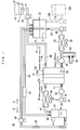
- [Fig. 1] A schematic diagram showing a primary portion of a fuel cell system according to the present invention.
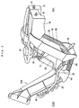
- [Fig. 2] A perspective view showing the fuel cell system mounted on a frame of a motorbike.
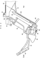
- [Fig. 3] A schematic view showing a primary portion of the fuel cell system.
- [Fig. 4] A block diagram showing an electric configuration of the fuel cell system.
- [Fig. 5] Fig. 5 (a) shows table data indicating a relationship between fuel cell temperatures and target amounts of aqueous solution; Fig. 5(b) is a graph thereof.
- [Fig. 6] A flowchart showing an example of main operation of the fuel cell system at a start-up.
- [Fig. 7] A flowchart showing an example of main operation of the fuel cell system after starting power generation.
- [Fig. 8] A flowchart showing another example of main operation of the fuel cell system after starting power generation.
- [Fig. 9] Fig. 9(a) shows table data indicating a relationship between amounts of charge in a secondary battery and target amounts of aqueous solution; Fig. 9(b) is a graph thereof.
-
- 10
- Fuel cell system
- 12
- Fuel cell
- 12b
- Anode
- 15, 22, 54
- Level sensors
- 18
- Aqueous solution tank
- 40, 42, 108
- Pipes
- 41
- Fuel supplying means
- 44
- Water tank
- 58
- Water recycling pipe
- 60
- Water pump
- 66
- Temperature sensor
- 70
- Control circuit
- 72
- CPU
- 76
- Memory
- 102
- Secondary battery
- 103
- Electric charge detector
- 106
- Relief tank
- 110
- Pump
- 200
- Vehicle frame
- 202
- Motor
- S
- Aqueous methanol solution
- Hereinafter, an embodiment of the present invention will be described with reference to the drawings.
As shown in Fig. 1 through Fig. 4, afuel cell system 10 as an embodiment of the present invention is a direct methanol fuel cell system. Direct methanol fuel cell systems do not require a reformer and so can be utilized suitably in equipment which requires portability, as well as in equipment in which size reduction is desirable. In the present description, thefuel cell system 10 is used on a motorbike as an example of transportation equipment. Note, however, that the motorbike will be represented only by avehicle frame 200 as shown in Fig. 2. Note also that as in Fig. 2, the left side of the diagram represents the front of the vehicle while the right side represents the rear of the vehicle. Further, thefuel cell system 10 is disposed along thevehicle frame 200. - Referring mainly to Fig. 1, the
fuel cell system 10 includes afuel cell 12. Thefuel cell 12 is configured as a fuel cell stack composed of a plurality of direct methanol fuel cells connected in series (into a layer), each including anelectrolyte 12a, an anode (fuel electrode) 12b and a cathode (air electrode) 12c which sandwich theelectrolyte 12a in between. - The
fuel cell system 10 includes afuel tank 14 which stores highly concentrated methanol fuel (aqueous solution containing approximately 50 weight percent of methanol) F. Thefuel tank 14 is connected, via afuel supply pipe 16, with anaqueous solution tank 18 which stores aqueous methanol solution S which serves as aqueous fuel solution. Thefuel supply pipe 16 is provided with afuel pump 20. Thefuel pump 20 supplies theaqueous solution tank 18 with the methanol fuel F from thefuel tank 14. - The
fuel tank 14 is provided with alevel sensor 15 for detecting the level of methanol fuel F in thefuel tank 14. Similarly, theaqueous solution tank 18 is provided with alevel sensor 22 for detecting the level of aqueous methanol solution S in theaqueous solution tank 18. Thelevel sensors level sensor 54 to be described later. - The
aqueous solution tank 18 is connected, via anaqueous solution pipe 24, with theanode 12b of thefuel cell 12. Theaqueous solution pipe 24 is provided with anaqueous solution pump 26, aradiator 28 functioning as a heat exchanger, and anaqueous solution filter 30, in this order from the upstream side. A coolingfan 32 is provided near theradiator 28 in order to cool theradiator 28. The aqueous methanol solution S in theaqueous solution tank 18 is pumped by theaqueous solution pump 26 toward theanode 12b, cooled by theradiator 28 as necessary, and purified by theaqueous solution filter 30 before being supplied to theanode 12b. - On the other hand, the
cathode 12c in thefuel cell 12 is connected with anair pump 34 via anair pipe 36. Theair pipe 36 is provided with an air filter 38. Thus, air which contains oxygen is sent from theair pump 34, purified by the air filter 38 and then supplied to thecathode 12c. - The
anode 12b and theaqueous solution tank 18 are connected with each other via apipe 40, so unused aqueous methanol solution and produced carbon dioxide discharged from theanode 12b are supplied to theaqueous solution tank 18. - In the present embodiment,
fuel supplying means 41 includes theaqueous solution tank 18, theaqueous solution pipe 24, theaqueous solution pump 26, theradiator 28, theaqueous solution filter 30, the coolingfan 32 and thepipe 40. Thefuel supplying means 41 provides circular supply of the aqueous methanol solution S to theanode 12b in thefuel cell 12. - Further, the
cathode 12c is connected with thewater tank 44 via apipe 42. Thepipe 42 is provided with aradiator 46 which functions as a gas-liquid separator. A coolingfan 48 is disposed near theradiator 46 in order to cool theradiator 46. Exhaust containing water (water and water vapor) which is discharged from thecathode 12c is supplied to thewater tank 44 via thepipe 42. Anair pump 34 is driven to promote introduction of the exhaust into thewater tank 44. - Further, the
aqueous solution tank 18 and thewater tank 44 are connected with each other via a CO2 vent pipe 50. The CO2 vent pipe 50 is provided with amethanol trap 52 in order to separate aqueous methanol solution S. The carbon dioxide discharged from theaqueous solution tank 18 is thus supplied to thewater tank 44. - The
water tank 44 is provided with alevel sensor 54, which detects the level of water in thewater tank 44. Thewater tank 44 is provided with anexhaust gas pipe 56. Theexhaust gas pipe 56 discharges carbon dioxide and the exhaust from thecathode 12c. Thewater tank 44 thus stores water which is produced by the electrochemical reaction, and a small amount of methanol carried as a result of crossover, in the form of liquid. - The
water tank 44 is connected with theaqueous solution tank 18 via awater recycling pipe 58. Thewater recycling pipe 58 is provided with awater pump 60. In the present embodiment, thewater pump 60 is capable of pumping the aqueous solution and water in Direction A or Direction B selectively. By switching the pumping direction of thewater pump 60 depending on the situation of theaqueous solution tank 18, the aqueous solution from thewater tank 44 is sent either to the aqueous solution tank 18 (Direction indicated by Arrow A) or vice versa (Direction indicated by Arrow B). In the present embodiment, thewater recycling pipe 58 has an end extended into theaqueous solution tank 18 so as to submerge into the aqueous solution. In other words, according to thefuel cell system 10, flow of the aqueous methanol solution S can be branched off a circular supply route for temporary storage in a separate storage space (tank), so it is easy to reduce the amount of aqueous solution in circulation. - Further, in the
aqueous solution pipe 24, abypass pipe 62 is formed between theradiator 28 and theaqueous solution filter 30. - Reference is now also made to Fig. 4. In the
fuel cell system 10, thebypass pipe 62 is provided with aconcentration sensor 64 which detects the concentration of aqueous methanol solution S.A temperature sensor 66 which detects the temperature offuel cell 12 is attached to thefuel cell 12. Anambient temperature sensor 68 which detects the ambient temperature is provided near theair pump 34. In the present embodiment, the temperature of thefuel cell 12 detected by thetemperature sensor 66 is regarded as the temperature of aqueous methanol solution S in circulation. Alternatively, the temperature of thecell stack 12 itself may be detected as the temperature of thefuel cell 12, and still another alternative is to detect the temperature of the exhaust from thecathode 12c. - As shown in Fig. 4, the
fuel cell system 10 includes acontrol circuit 70.
Thecontrol circuit 70 includes: aCPU 72 serving as control means which performs necessary arithmetic operations and provides control over the operation of thefuel cell system 10; aclock circuit 74 which provides theCPU 72 with clock signals; amemory 76 which may be provided by an EEPROM for example for storing programs and data for controlling thefuel cell system 10, calculation data, etc; areset IC 78 which prevents thefuel cell system 10 from faulty operations; aninterface circuit 82 for connection with external devices; avoltage detection circuit 84 for detecting the voltage in anelectric circuit 82 which connects thefuel cell 12 with amotor 202 that drives the motorbike; an electriccurrent detection circuit 86 for detecting the electric current flowing in theelectric circuit 82; an ON/OFF circuit 88 which opens and closes theelectric circuit 82; avoltage protection circuit 90 which prevents over voltage in theelectric circuit 82; adiode 92 provided in theelectric circuit 82; and apower source circuit 94 which supplies a predetermined voltage to theelectric circuit 82. - In the
control circuit 70 described as the above, theCPU 72 is supplied with detection signals from theconcentration sensor 64, thetemperature sensor 66 and theambient temperature sensor 68, as well as detection signals from a roll-over switch 96 which detects whether or not the vehicle is rolled over, and signals from aninput unit 98 for settings and data input. Further, theCPU 72 is supplied with detection signals from thelevel sensors - The
CPU 72 provides control on such components as thefuel pump 20, theaqueous solution pump 26, theair pump 34, the heatexchanger cooling fan 32, the gas-liquidseparator cooling fan 48, and thewater pump 60. Also, theCPU 72 controls adisplay 100 which displays various kinds of information for the rider of the motorbike. - Further, the
fuel cell 12 is connected with asecondary battery 102 and anelectric charge detector 103 which detects the amount of charge (remaining power) in thesecondary battery 102. Thesecondary battery 102 and theelectric charge detector 103 which are connected with each other in series have a parallel connection with themotor 202. Thesecondary battery 102, which provides power to supplement the output from thefuel cell 12, is charged by thefuel cell 12 with electric energy, and gives electric energy to themotor 202 and the other components, by discharging. - The
motor 202 is connected with ameter 204 for various measurements on themotor 202. Data and status information about themotor 202 measured by themeter 204 are supplied to theCPU 72 via aninterface circuit 104. - The
memory 76 stores table data as shown in Fig. 5(a) which relates the temperature of thefuel cell 12 to a target amount of aqueous solution, programs for executing operations as shown in Fig. 6 through Fig. 8, and other information. Fig. 5(b) is a graph which shows the relationship between the temperature of thefuel cell 12 and the target amount of aqueous solution. The term target amount of aqueous solution is a target amount of aqueous methanol solution S to be stored in theaqueous solution tank 18. - As understood from Fig. 5, the target amount of aqueous solution is set higher as the fuel cell temperature becomes higher. When the temperature is high, if the
aqueous solution tank 18 is full, the amount of liquid which must be decreased (moved) from theaqueous solution tank 18 at the time of start up is small, enabling to reduce the amount of electricity necessary for moving the liquid to the separate tank. On the other hand, the target amount of aqueous solution is set smaller as the fuel cell temperature becomes lower. When the temperature is low, a large amount of aqueous solution is moved to the other tank, enabling to increase the temperature rising speed at an early period of start up. - It should be noted that in normal operation, a greater amount of aqueous methanol solution S in the
aqueous solution tank 18 leads to more stable temperature of the aqueous methanol solution S which is circulating in thefuel cell 12 and the fuel supplying means 41, and to smaller fluctuation in the concentration of methanol in the aqueous solution. For this reason, a greater amount of aqueous methanol solution is generally more preferable in operating thefuel cell system 10. - In the present embodiment, aqueous-solution-amount adjusting means includes the
water recycling pipe 58, thewater pump 60 and thecontrol circuit 70. - An operation of the
fuel cell system 10 at a time of power generation will be described.
When power generation is started, aqueous methanol solution S which is stored in theaqueous solution tank 18 and has a desired level of concentration is pumped by theaqueous solution pump 26 toward thefuel cell 12. The solution is cooled as necessary by theradiator 28, purified by theaqueous solution filter 30, and then supplied to theanode 12b. On the other hand, air which contains oxygen is pumped by theair pump 34 toward thefuel cell 12. The air is purified by the air filter 38 and then supplied to thecathode 12c. - On the
anode 12b in thefuel cell 12, methanol and water in the aqueous methanol solution S react electro-chemically with each other to produce carbon dioxide and hydrogen ions. The hydrogen ions move through theelectrolyte 12a to thecathode 12c, where the hydrogen ions react electro-chemically with oxygen in the air which is supplied to thecathode 12c, to produce water (water vapor) and electric energy. - Carbon dioxide which occurred on the
anode 12b in thefuel cell 12 flows through thepipe 40, theaqueous solution tank 18 and the CO2 vent pipe 50 to thewater tank 44, and then it is discharged from theexhaust gas pipe 56. - On the other hand, most of the water vapor occurred on the
cathode 12c in thefuel cell 12 is liquefied and discharged in the form of water, with saturated water vapor being discharged in the form of gas. Part of the water vapor which was discharged from thecathode 12c is cooled by theradiator 46 and liquefied by lowering the dew point. Liquefaction of the water vapor by theradiator 46 is performed by operation of the coolingfan 48. Water (water and water vapor) and unused air from thecathode 12c are supplied to thewater tank 44 via thepipe 42. Also, water which has moved to thecathode 12c due to water crossover is discharged from thecathode 12c and supplied to thewater tank 44. Further, water and carbon dioxide which occurred at thecathode 12c due to methanol crossover are discharged from thecathode 12c and supplied to thewater tank 44. - It should be noted here that the term water crossover is a phenomenon in which a few mols of water moves to the
cathode 12c, accompanying the hydrogen ions which occur at theanode 12b and are moving to thecathode 12c. The term methanol crossover is a phenomenon in which methanol moves to thecathode 12c, accompanying the hydrogen ions which move to thecathode 12c. Methanol which has moved to thecathode 12c reacts with air supplied from theair pump 34, thereby decomposed into water and carbon dioxide. - Water (liquid) which was collected in the
water tank 44 is recycled appropriately by thewater pump 60, through thewater recycling pipe 58 to theaqueous solution tank 18, where the water is used for the aqueous methanol solution S. - Next, description will be made for an example of main operation of the
fuel cell system 10 at the time of start up.
Referring to Fig. 6, first, when an unillustrated main switch is turned ON, a "main switch ON" signal is inputted to the CPU 72 (Step S1), and the system waits for a rise of power source voltage. When the power source voltage becomes stable, theelectric charge detector 103 detects the amount of charge (remaining power) in the secondary battery 102 (Step S3) . Based on the detected amount of charge in thesecondary battery 102, the system checks if thewater pump 60 is drivable or not (Step S5). - If the detected amount of charge in the
secondary battery 102 is sufficient to supply power which is necessary for generating electricity (i.e. power for driving the system components), the system determines that it can drive thewater pump 60. Then, thetemperature sensor 66 detects the temperature of the fuel cell 12 (Step S7). - The system then makes reference to the table data shown in Fig. 5, to select/determine a target amount of aqueous solution corresponding to the temperature detected in Step S7 (Step S9) . Then, the
level sensor 22 detects the current amount of aqueous methanol solution S in the aqueous solution tank 18 (Step S11). The system checks if the detected amount of aqueous solution is greater than the target amount of aqueous solution which was found on the basis of the fuel cell temperature, i.e. the temperature of aqueous fuel solution (Step S13). If the detected amount of aqueous solution is greater (Step S13: YES), the power in thesecondary battery 102 is used to drive thewater pump 60, whereby aqueous methanol solution S in theaqueous solution tank 18 is sent through thewater recycling pipe 58 to the water tank 44 (in the direction B as in Fig. 1) (Step S15). The system then checks if the amount of aqueous solution in theaqueous solution tank 18 has reached the target amount of aqueous solution (Step S17). If the amount of aqueous solution in theaqueous solution tank 18 has not yet reached the target amount of aqueous solution, pumping of the aqueous methanol solution S is continued until Step S19 finds that a predetermined amount of time has passed. After the lapse of the predetermined amount of time, Step S17 checks again if the target amount of aqueous solution has been reached. The pumping of aqueous methanol solution S is continued until S17 finds that the amount of aqueous solution in theaqueous solution tank 18 has reached the target amount of aqueous solution. Once Step S17 gives "YES", thewater pump 60 is stopped (Step S21). - On the other hand, if Step S13 finds that the amount of aqueous solution in the
aqueous solution tank 18 is not greater than the target amount of aqueous solution, the system checks if the amount of aqueous solution is smaller than the target amount of aqueous solution (Step S23). If the amount of aqueous solution is smaller than the target amount of aqueous solution, power in thesecondary battery 102 is used to drive thewater pump 60, to send water or aqueous solution in thewater tank 44 to theaqueous solution tank 18 through the water recycling pipe 58 (in the direction A as in Fig. 1) (Step S25). The amount of aqueous solution in theaqueous solution tank 18 can be smaller than the target amount of aqueous solution when, for example, a long time has passed since power generating operation was stopped and crossover has caused aqueous solution to leak out of theaqueous solution tank 18. - Then, the system checks if the above-described adjustment on the amount of aqueous solution has brought the amount of the aqueous solution in the
aqueous solution tank 18 to the target amount of aqueous solution (Step S27) . If the amount of aqueous solution in theaqueous solution tank 18 has not yet reached the target amount of aqueous solution, pumping of water or aqueous solution is continued until Step S29 finds a predetermined amount of time has passed. After the lapse of the predetermined amount of time, Step S27 checks again, if the amount has reached the target amount of aqueous solution. The above-described pumping is continued until Step S27 finds the amount of aqueous solution in theaqueous solution tank 18 has reached the target amount of aqueous solution. Once Step S27 gives "YES", thewater pump 60 is stopped (Step S21). - With the above, if Step S23 gives "NO", i.e. if the amount of aqueous solution in the
aqueous solution tank 18 is equal to the target amount of aqueous solution, the system proceeds directly to Step S21. - After Step S21, adjustment is made so that the aqueous solution in the
aqueous solution tank 18 has a desired concentration (Step S30). During this step, the concentration of aqueous solution is detected by, for example, a concentration sensor (not illustrated) provided in theaqueous solution tank 18. If the concentration of the aqueous solution is lower than the desired value, methanol fuel is added from thefuel tank 14 whereas water or aqueous solution is added from thewater tank 44 if the concentration is higher than the desired value. - Thereafter, system components such as the
fuel pump 20, theaqueous solution pump 26, theair pump 34, the heat-exchanger cooling fan 32, the gas-liquid-separator cooling fan 48 and thewater pump 60 are driven to generate power (Step S31). - It should be noted that if the amount of charge in the
secondary battery 102 is too small to cover the amount of power necessary for generating electricity (i.e. for driving system components), the system determines in Step S5 that it is impossible to drive thewater pump 60. In this case, thewater pump 60 is not driven to protect thefuel cell system 10 from shutting down, but a different step is performed (Step S33), to proceed to Step S31 and begin power generation. - Next, reference will be made to Fig. 7 to describe an example of main operation of the
fuel cell system 10 after power generation has been started. In this example, the amount of aqueous solution in theaqueous solution tank 18 is brought back to a predetermined level by gradually increasing the amount in accordance with temperature increase in thefuel cell 12. - As the
fuel cell system 10 starts power generation, thetemperature sensor 66 detects the temperature of the fuel cell 12 (Step S51). The system makes reference to the table data shown in Fig. 5, to select/determine a target amount of aqueous solution which corresponds to the detected temperature (Step S53). Then, thelevel sensor 22 detects the current amount of aqueous methanol solution S in the aqueous solution tank 18 (Step S55). The system checks if the detected amount of aqueous solution is not smaller than the target amount of aqueous solution (Step S57). If the detected amount of aqueous solution is smaller than the target amount of aqueous solution, thewater pump 60 is driven, whereby water or aqueous solution in thewater tank 44 is sent to theaqueous solution tank 18 via the water recycling pipe 58 (in the direction A as in Fig. 1) (Step S59). The system then checks if the amount of aqueous solution in theaqueous solution tank 18 has reached the target amount of aqueous solution (Step S61). If the amount of aqueous solution in theaqueous solution tank 18 has not yet reached the target amount of aqueous solution, pumping of water or aqueous solution is continued until Step S63 finds that a predetermined amount of time has passed. After the lapse of the predetermined amount of time, Step S61 checks again if the target amount of aqueous solution has been reached. The above-described pumping is continued until Step S61 finds that the amount of aqueous solution in theaqueous solution tank 18 has reached the target amount of aqueous solution. Once Step S61 gives "YES", thewater pump 60 is stopped (Step S65). Thereafter, adjustment is made so that the concentration of aqueous solution in theaqueous solution tank 18 is desirable (Step S66). - Next, the system checks if the
aqueous solution tank 18 is full, i.e. if the amount of liquid is for normal operation (which is 3L in the present embodiment) (Step S67). If theaqueous solution tank 18 is full, normal operation is commenced. If theaqueous solution tank 18 is not full, the system waits until a predetermined amount of time has passed (Step S69: YES), and then brings the process back to Step S51, where the above-described cycle is repeated until theaqueous solution tank 18 becomes full. - According to the
fuel cell system 10 as described above, the amount of aqueous methanol solution S which is in circulation at the time of system start up is smaller than the amount during the normal operation, whereby it becomes possible to decrease thermal capacity of the aqueous methanol solution S which is in circular supply to thefuel cell 12. Therefore, it becomes possible to shorten the time required for heating the aqueous methanol solution S to a predetermined temperature (65°C, for example), enabling to increase the amount of generated power quickly after the start up. Further, since heating is not provided by oxidization of the aqueous methanol solution S, fuel utilization efficiency does not decrease. - Further, by only adjusting the amount of aqueous methanol solution S in the
aqueous solution tank 18, the amount of aqueous methanol solution S in thefuel supplying means 41 is adjusted easily. - Moreover, an extra amount of aqueous methanol solution S is moved from the fuel supplying means 41 to the
water tank 44. Therefore, there is no need for an extra tank. - Further, the amount of aqueous methanol solution S in the fuel supplying means 41 at an early stage is adjusted on the basis of the temperature of the
fuel cell 12, whereby it becomes possible to increase the temperature of aqueous methanol solution S quickly while keeping temperature stability of thefuel cell 12. Further, there is no need for excessively decreasing the amount of aqueous methanol solution S, drive time of thewater pump 60 can be optimized, and power consumption can be decreased. - Moreover, at the time of normal operation after the predetermined temperature has been attained, the amount of aqueous methanol solution S is at a predetermined level, i.e. the
aqueous solution tank 18 is full. This provides sufficient thermal capacity and stabilizes the system temperature, the concentration of aqueous methanol solution S, etc. - Further, after starting power generation, the amount of aqueous methanol solution S in the
fuel supplying means 41 is set in a stepped manner in accordance with the temperature of thefuel cell 12 and the amount is increased gradually. Therefore, it is possible to bring the amount of aqueous methanol solution S back to a predetermined amount without sacrificing the temperature stability of thefuel cell 12. - Next, reference will be made to Fig. 8 to describe another example of the main operation after the
fuel cell system 10 has started power generation. In this example, the fuel cell temperature is increased to a predetermined temperature, and then the amount of aqueous solution is brought back to a predetermined amount while maintaining the temperature stably. - As the
fuel cell system 10 starts power generation, thetemperature sensor 66 detects the temperature of the fuel cell 12 (Step S101) . The system checks if the temperature of thefuel cell 12 has reached a predetermined temperature (65°C for example) (Step S103). If the temperature of thefuel cell 12 has not reached the predetermined temperature, the system waits until a predetermined amount of time has passed (Step S105: YES), and then goes back to Step S101 again, to repeat the above-described cycle until the predetermined temperature is reached. When Step S103 finds that the temperature of thefuel cell 12 has reached the predetermined temperature, the system checks if theaqueous solution tank 18 is full or not (Step S107) . If theaqueous solution tank 18 is not full, the system checks if the temperature of thefuel cell 12 is not lower than a predetermined temperature (65°C for example) (Step S109). If the temperature of thefuel cell 12 is lower than the predetermined temperature, the system waits until a predetermined amount of time has passed (Step S111: YES), and then goes back to Step S107 again. If theaqueous solution tank 18 is not full (Step S107: NO) and the temperature of thefuel cell 12 is not lower than the predetermined temperature (Step S109: YES), thewater pump 60 is driven to send water or aqueous solution from thewater tank 44 to theaqueous solution tank 18 via the water recycling pipe 58 (Step S113). Then, the system checks if the temperature of thefuel cell 12 is not lower than a predetermined temperature (65°C for example) (Step S115). If the temperature of thefuel cell 12 is not lower than the predetermined temperature, the system waits until a predetermined amount of time has passed (Step S117: YES), and then goes back again to Step S115 again. In other words, water or aqueous solution is pumped until the temperature of thefuel cell 12 goes down below a predetermined temperature (65°C for example). In this way the amount of aqueous solution in theaqueous solution tank 18 is increased. - Once the temperature of the
fuel cell 12 has dropped down below a predetermined temperature (65°C for example), thewater pump 60 is stopped (Step S119), adjustment is made so that the concentration of the aqueous solution in theaqueous solution tank 18 is desirable (Step S120), and the program goes back to Step S107, where the above-described cycle of process is repeated until theaqueous solution tank 18 becomes full. Once theaqueous solution tank 18 is full, the system proceeds to normal operation. - According to the
fuel cell system 10 which operates as described above, the amount of aqueous methanol solution S in thefuel supplying means 41 is increased in such a way that the temperature of thefuel cell 12 stays at a predetermined level. Therefore, it is possible to bring the amount of aqueous methanol solution S back to a predetermined amount without impairing temperature stability of thefuel cell 12. - Note that the amount of aqueous solution in the
aqueous solution tank 18 may be increased to the full level (the amount for the normal operation) in a single step once the temperature of thefuel cell 12 has reached a predetermined level after thefuel cell system 10 started power generation. This enables to shift to the normal operation quickly. - As another alternative, the
memory 76 may store table data as shown in Fig. 9(a). The data relates the amount of charge in thesecondary battery 102 to the target amount of aqueous solution for the system to set an initial amount of aqueous methanol solution S in theaqueous solution tank 18 in accordance with the amount of charge in thesecondary battery 102. Thefuel cell 12 must be heated to a predetermined temperature (65°C approx.) more quickly if the amount of charge in thesecondary battery 102 is smaller. Therefore, the system sets the amount of aqueous solution in theaqueous solution tank 18 to a smaller amount if the amount of charge is smaller. Fig. 9 (b) is a graph which shows a relationship between the amount of charge in thesecondary battery 12 and the target amount of aqueous solution. - As described, by adjusting the initial amount of aqueous methanol solution S in the fuel supplying means 41 based on the amount of charge in the
secondary battery 12, it becomes possible to heat aqueous methanol solution S to a predetermined temperature desirable for power generation before the amount of charge in thesecondary battery 12 has depleted. - As another alternative, aqueous methanol solution S in the
aqueous solution tank 18 may not be sent to thewater tank 44 as shown in Fig. 1, but instead be sent to aseparate relief tank 106. Therelief tank 106 is connected with theaqueous solution tank 18 via apipe 108, and thepipe 108 is provided with apump 110 which is capable of pumping in whichever of the two directions. As shown in Fig. 4, thepump 110 is controlled by aCPU 72. In this case, thepipe 108, thepump 110 and acontrol circuit 70 are included in the aqueous-solution-amount adjusting means. By driving thepump 110, aqueous solution is sent from theaqueous solution tank 18 to therelief tank 106 or in the opposite direction. - An extra amount of aqueous methanol solution S in the
fuel supplying means 41 is moved to therelief tank 106, so there is no need for modifying the existingfuel cell system 10 nor risk of making affect to other components which constitute the existingfuel cell system 10. - In the embodiment described above, the amount of aqueous solution in the
aqueous solution tank 18 is changed in order to adjust the amount of aqueous solution in thefuel supplying means 41 and thereby to adjust the amount of aqueous solution circulated by thefuel supplying means 41. However, the present invention is not limited by this. The amount of aqueous solution may be changed at any desired portion within the fuel supplying means 41, such as at theaqueous solution pipe 24, thepipe 40, etc. - Still another variation may be that a movable partition plate is provided within the
aqueous solution tank 18. The partition plate is moved to divide the aqueous solution in theaqueous solution tank 18 into two bodies, one for circulation and the other for non-circulation, whereby adjustment is made on the amount of aqueous methanol solution S which is circulating in thefuel cell 12 and thefuel supplying means 41. - The detection means for the amount of aqueous solution in the
aqueous solution tank 18 is not limited to those based on the liquid level in the tank, but may be of any other type. - The aqueous fuel solution is not limited to aqueous methanol solution, but may be other aqueous alcohol solutions or the like.
- Further, temperature detection may not be made to the
fuel cell 12, but may be made directly to the aqueous fuel solution. - The
fuel cell system 10 can be utilized suitably not only in motorcycles but also in automobiles, marine vessels, and any other transportation equipment. - The present invention is also applicable to fuel cell systems which make use of a reformer. Further, the present invention is applicable to small-scale, stationary-type fuel cell systems.
- The present invention being thus far described and illustrated in detail, it is obvious that these description and drawings only represent examples of the present invention, and should not be interpreted as limiting the invention. The spirit and scope of the present invention is only limited by words used in the accompanied claims.
Claims (19)
- A fuel cell system comprising:a fuel cell including an anode;fuel supplying means for circular supply of aqueous fuel solution to the anode of the fuel cell; andaqueous-solution-amount adjusting means for setting an amount of aqueous fuel solution in the fuel supplying means for a start-up to an amount smaller than for a normal operation.
- The fuel cell system according to Claim 1, wherein the fuel supplying means includes an aqueous solution tank for storing the aqueous fuel solution,
the aqueous-solution-amount adjusting means adjusting an amount of aqueous fuel solution in the aqueous solution tank. - The fuel cell system according to Claim 2, further comprising a tank separately from the aqueous solution tank, for storing the aqueous fuel solution,
wherein the aqueous-solution-amount adjusting means is capable of moving aqueous fuel solution from the aqueous solution tank to the separate tank. - The fuel cell system according to Claim 1, further comprising a water tank for storing liquid discharged from the fuel cell,
wherein the aqueous-solution-amount adjusting means is capable of moving aqueous fuel solution from the fuel supplying means to the water tank. - The fuel cell system according to Claim 1, further comprising a relief tank for receiving the aqueous fuel solution from the fuel supplying means,
wherein the aqueous-solution-amount adjusting means is capable of moving aqueous fuel solution from the fuel supplying means to the relief tank. - The fuel cell system according to Claim 1, further comprising temperature detecting means for detecting a temperature of the fuel cell,
wherein the aqueous-solution-amount adjusting means adjusts the amount of aqueous fuel solution in the fuel supplying means in accordance with the temperature of the fuel cell detected by the temperature detecting means. - The fuel cell system according to Claim 1, further comprising: a secondary battery electrically connected with the fuel cell; and amount-of-charge detection means for detecting an amount of charge in the secondary battery,
wherein the aqueous-solution-amount adjusting means adjusts the amount of aqueous fuel solution in the fuel supplying means in accordance with the amount of charge detected by the amount-of-charge detecting means. - The fuel cell system according to Claim 1, wherein the aqueous-solution-amount adjusting means increases the amount of aqueous fuel solution in the fuel supplying means to a predetermined amount for the normal operation after the start-up operation.
- The fuel cell system according to Claim 8, further comprising temperature detecting means for detecting a temperature of the fuel cell,
wherein the aqueous-solution-amount adjusting means increases the amount of aqueous fuel solution in the fuel supplying means in accordance with the temperature of the fuel cell detected by the temperature detecting means. - The fuel cell system according to Claim 8, further comprising temperature detecting means for detecting a temperature of the fuel cell,
wherein the aqueous-solution-amount adjusting means increases the amount of aqueous fuel solution in the fuel supplying means when the temperature of the fuel cell detected by the temperature detecting means has reached a predetermined temperature, in such a way that the temperature of the fuel cell will stay at the predetermined temperature. - The fuel cell system according to Claim 8, further comprising temperature detecting means for detecting a temperature of the fuel cell,
wherein the aqueous-solution-amount adjusting means increases the amount of aqueous fuel solution in the fuel supplying means to the predetermined amount when the temperature of the fuel cell detected by the temperature detecting means has reached a predetermined temperature. - Transportation equipment including the fuel cell system according to one of Claims 1 through 11.
- A method of controlling a fuel cell system, the system including a fuel cell having an anode, and fuel supplying means for circular supply of aqueous fuel solution to the anode of the fuel cell,
the method comprising a step of setting an amount of aqueous fuel solution in the fuel supplying means for a start-up to an amount smaller than for a normal operation. - The method according to Claim 13, wherein the amount of aqueous fuel solution in the fuel supplying means is adjusted, based on a temperature of the fuel cell.
- The method according to Claim 13, wherein the fuel cell system includes a secondary battery electrically connected with the fuel cell,
wherein the amount of aqueous fuel solution in the fuel supplying means is adjusted, based on an amount of charge in the secondary battery. - The method according to Claim 13, wherein the amount of aqueous fuel solution in the fuel supplying means is increased to a predetermined amount for the normal operation after the start-up operation.
- The method according to Claim 16, wherein the amount of aqueous fuel solution in the fuel supplying means is increased in accordance with a temperature of the fuel cell.
- The method according to Claim 16, wherein the amount of aqueous fuel solution in the fuel supplying means is increased when a temperature of the fuel cell has reached a predetermined temperature, in such a way that the temperature of the fuel cell will stay at the predetermined temperature.
- The method according to Claim 16, wherein the amount of aqueous fuel solution in the fuel supplying means is increased to the predetermined amount when a temperature of the fuel cell has reached a predetermined temperature.
Applications Claiming Priority (2)
| Application Number | Priority Date | Filing Date | Title |
|---|---|---|---|
| JP2004251385 | 2004-08-31 | ||
| PCT/JP2005/015655 WO2006025321A1 (en) | 2004-08-31 | 2005-08-29 | Fuel cell system and method for controlling the same |
Publications (2)
| Publication Number | Publication Date |
|---|---|
| EP1821358A1 true EP1821358A1 (en) | 2007-08-22 |
| EP1821358A4 EP1821358A4 (en) | 2007-11-21 |
Family
ID=35999975
Family Applications (1)
| Application Number | Title | Priority Date | Filing Date |
|---|---|---|---|
| EP05775106A Withdrawn EP1821358A4 (en) | 2004-08-31 | 2005-08-29 | FUEL CELL SYSTEM AND METHOD OF CONTROLLING SAID SYSTEM |
Country Status (4)
| Country | Link |
|---|---|
| US (1) | US8263283B2 (en) |
| EP (1) | EP1821358A4 (en) |
| JP (1) | JP5074032B2 (en) |
| WO (1) | WO2006025321A1 (en) |
Cited By (1)
| Publication number | Priority date | Publication date | Assignee | Title |
|---|---|---|---|---|
| EP1887645A3 (en) * | 2006-07-31 | 2009-04-08 | Yamaha Hatsudoki Kabushiki Kaisha | Fuel cell system and control method thereof |
Families Citing this family (5)
| Publication number | Priority date | Publication date | Assignee | Title |
|---|---|---|---|---|
| JP5201902B2 (en) * | 2006-07-31 | 2013-06-05 | ヤマハ発動機株式会社 | Fuel cell system and control method thereof |
| JP2008257945A (en) * | 2007-04-03 | 2008-10-23 | Hitachi Ltd | Fuel cell starting method and fuel cell power generation system |
| RU2477909C2 (en) * | 2008-08-18 | 2013-03-20 | Сони Корпорейшн | Fuel element system and electronic device |
| JP6021630B2 (en) * | 2012-12-19 | 2016-11-09 | ダイハツ工業株式会社 | Fuel cell system |
| CN107464944B (en) | 2016-05-27 | 2021-02-02 | 通用电气公司 | Fuel cell system and method of operating the same |
Family Cites Families (24)
| Publication number | Priority date | Publication date | Assignee | Title |
|---|---|---|---|---|
| JPS5159353A (en) * | 1974-11-20 | 1976-05-24 | Matsushita Electric Industrial Co Ltd | Nenryodenchino sadoho |
| JPS5823167A (en) * | 1981-08-03 | 1983-02-10 | Nissan Motor Co Ltd | Power device for fuel cell |
| JPS58165274A (en) * | 1982-03-26 | 1983-09-30 | Hitachi Ltd | Fuel cell |
| JPS6145569A (en) | 1984-08-09 | 1986-03-05 | Nissan Motor Co Ltd | Power supply for automobile |
| JPS62128459A (en) * | 1985-11-28 | 1987-06-10 | Shin Kobe Electric Mach Co Ltd | Control for liquid fuel cell |
| JPS63168971A (en) * | 1986-12-29 | 1988-07-12 | Hitachi Ltd | Fuel feeding method for fuel cell |
| WO2000033407A1 (en) * | 1998-12-01 | 2000-06-08 | Ballard Power Systems Inc. | Method and apparatus for controlling the temperature within an electrochemical fuel cell |
| DE10000514C2 (en) | 2000-01-08 | 2002-01-10 | Daimler Chrysler Ag | Fuel cell system and method for operating such a system |
| JP2002246052A (en) | 2001-02-20 | 2002-08-30 | Equos Research Co Ltd | Fuel cell device and start-up method thereof |
| US6821658B2 (en) * | 2001-03-02 | 2004-11-23 | Mti Microfuel Cells Inc. | Cold start and temperature control method and apparatus for fuel cell system |
| US6878473B2 (en) * | 2001-05-02 | 2005-04-12 | Kabushiki Kaisha Toshiba | Fuel cell power generating apparatus, and operating method and combined battery of fuel cell power generating apparatus |
| JP3460703B2 (en) * | 2001-05-28 | 2003-10-27 | 日産自動車株式会社 | Antifreezing device for fuel cell cooling system |
| JP4547554B2 (en) | 2001-06-13 | 2010-09-22 | ヤマハ発動機株式会社 | Electric vehicle |
| JP2002373684A (en) * | 2001-06-18 | 2002-12-26 | Yamaha Motor Co Ltd | Fuel cell system |
| US20030003336A1 (en) * | 2001-06-28 | 2003-01-02 | Colbow Kevin Michael | Method and apparatus for adjusting the temperature of a fuel cell by facilitating methanol crossover and combustion |
| AU2002243456A1 (en) * | 2002-01-04 | 2003-07-30 | International Fuel Cells, Llc | Procedure for starting up a fuel cell system having an anode exhaust recycle loop |
| US6884529B2 (en) * | 2002-02-06 | 2005-04-26 | E. I. Du Pont Canada Company | Method of heating up a solid polymer electrolyte fuel cell system |
| JP4013609B2 (en) | 2002-03-26 | 2007-11-28 | 松下電器産業株式会社 | Fuel cell system |
| JP3748434B2 (en) * | 2002-06-12 | 2006-02-22 | 株式会社東芝 | Direct methanol fuel cell system and fuel cartridge |
| JP3918999B2 (en) | 2002-07-23 | 2007-05-23 | 株式会社ジーエス・ユアサコーポレーション | Direct methanol fuel cell system and its operation method |
| TWI228332B (en) | 2002-09-18 | 2005-02-21 | Nec Corp | Fuel cell system and method of using same |
| CN1300886C (en) * | 2002-09-30 | 2007-02-14 | 株式会社杰士汤浅 | Liquid fuel direct supply fuel cell system and its operation controlling method and controller |
| JP3764426B2 (en) * | 2003-01-21 | 2006-04-05 | 株式会社東芝 | Electronic device and operation control method |
| JP5082220B2 (en) * | 2005-10-05 | 2012-11-28 | トヨタ自動車株式会社 | Fuel cell system |
-
2005
- 2005-08-29 US US11/574,457 patent/US8263283B2/en not_active Expired - Fee Related
- 2005-08-29 JP JP2006532669A patent/JP5074032B2/en not_active Expired - Fee Related
- 2005-08-29 WO PCT/JP2005/015655 patent/WO2006025321A1/en not_active Ceased
- 2005-08-29 EP EP05775106A patent/EP1821358A4/en not_active Withdrawn
Cited By (2)
| Publication number | Priority date | Publication date | Assignee | Title |
|---|---|---|---|---|
| EP1887645A3 (en) * | 2006-07-31 | 2009-04-08 | Yamaha Hatsudoki Kabushiki Kaisha | Fuel cell system and control method thereof |
| US9461317B2 (en) | 2006-07-31 | 2016-10-04 | Yamaha Hatsudoki Kabushiki Kaisha | Fuel cell system and control method therefor |
Also Published As
| Publication number | Publication date |
|---|---|
| JP5074032B2 (en) | 2012-11-14 |
| US8263283B2 (en) | 2012-09-11 |
| WO2006025321A1 (en) | 2006-03-09 |
| JPWO2006025321A1 (en) | 2008-05-08 |
| US20090214903A1 (en) | 2009-08-27 |
| EP1821358A4 (en) | 2007-11-21 |
Similar Documents
| Publication | Publication Date | Title |
|---|---|---|
| JP3722019B2 (en) | Fuel cell system | |
| US7662496B2 (en) | Fuel cell cooling system and method for controlling circulation of cooling liquid in fuel cell | |
| US8206858B2 (en) | Fuel cell system and starting method therefor | |
| JP2002313388A (en) | Fuel cell control method and fuel cell electric vehicle | |
| JP5350619B2 (en) | Fuel cell system and transportation equipment including the same | |
| EP1749324A2 (en) | Fuel cell system and control method therefor | |
| CN100349317C (en) | Fuel cell stack control device and method | |
| JP2005032610A (en) | FUEL CELL DEVICE AND FUEL CELL FUEL SUPPLY METHOD | |
| JP3876784B2 (en) | Fuel cell system | |
| US8110312B2 (en) | Fuel cell system and starting method therefor | |
| US8263283B2 (en) | Fuel cell system and control method thereof | |
| JP5103740B2 (en) | Fuel cell system and method for starting fuel cell system | |
| US8071244B2 (en) | Fuel cell system | |
| US20090123785A1 (en) | Fuel cell system and control method therefor | |
| JP5103739B2 (en) | Fuel cell system and fuel cell vehicle | |
| JP5252887B2 (en) | Fuel cell system and control method thereof | |
| JP4550491B2 (en) | Fuel cell system and transportation equipment using the same | |
| US9461317B2 (en) | Fuel cell system and control method therefor | |
| KR100786481B1 (en) | Method and Apparatus for Controlling Operation of Direct Methanol Fuel Cell System | |
| JP5147165B2 (en) | Fuel cell system and control method thereof | |
| JP2008257932A (en) | Fuel cell system | |
| JP2007128811A (en) | Fuel cell system and control method thereof |
Legal Events
| Date | Code | Title | Description |
|---|---|---|---|
| PUAI | Public reference made under article 153(3) epc to a published international application that has entered the european phase |
Free format text: ORIGINAL CODE: 0009012 |
|
| 17P | Request for examination filed |
Effective date: 20070319 |
|
| AK | Designated contracting states |
Kind code of ref document: A1 Designated state(s): AT BE BG CH CY CZ DE DK EE ES FI FR GB GR HU IE IS IT LI LT LU LV MC NL PL PT RO SE SI SK TR |
|
| A4 | Supplementary search report drawn up and despatched |
Effective date: 20071024 |
|
| DAX | Request for extension of the european patent (deleted) | ||
| 17Q | First examination report despatched |
Effective date: 20080401 |
|
| STAA | Information on the status of an ep patent application or granted ep patent |
Free format text: STATUS: THE APPLICATION IS DEEMED TO BE WITHDRAWN |
|
| 18D | Application deemed to be withdrawn |
Effective date: 20190514 |