EP1821265A1 - Bill identification and counting machine - Google Patents
Bill identification and counting machine Download PDFInfo
- Publication number
- EP1821265A1 EP1821265A1 EP04773790A EP04773790A EP1821265A1 EP 1821265 A1 EP1821265 A1 EP 1821265A1 EP 04773790 A EP04773790 A EP 04773790A EP 04773790 A EP04773790 A EP 04773790A EP 1821265 A1 EP1821265 A1 EP 1821265A1
- Authority
- EP
- European Patent Office
- Prior art keywords
- rollers
- bill
- bills
- transport path
- side hopper
- Prior art date
- Legal status (The legal status is an assumption and is not a legal conclusion. Google has not performed a legal analysis and makes no representation as to the accuracy of the status listed.)
- Granted
Links
Images




Classifications
-
- G—PHYSICS
- G07—CHECKING-DEVICES
- G07D—HANDLING OF COINS OR VALUABLE PAPERS, e.g. TESTING, SORTING BY DENOMINATIONS, COUNTING, DISPENSING, CHANGING OR DEPOSITING
- G07D11/00—Devices accepting coins; Devices accepting, dispensing, sorting or counting valuable papers
- G07D11/10—Mechanical details
-
- B—PERFORMING OPERATIONS; TRANSPORTING
- B65—CONVEYING; PACKING; STORING; HANDLING THIN OR FILAMENTARY MATERIAL
- B65H—HANDLING THIN OR FILAMENTARY MATERIAL, e.g. SHEETS, WEBS, CABLES
- B65H5/00—Feeding articles separated from piles; Feeding articles to machines
- B65H5/06—Feeding articles separated from piles; Feeding articles to machines by rollers or balls, e.g. between rollers
- B65H5/062—Feeding articles separated from piles; Feeding articles to machines by rollers or balls, e.g. between rollers between rollers or balls
-
- B—PERFORMING OPERATIONS; TRANSPORTING
- B65—CONVEYING; PACKING; STORING; HANDLING THIN OR FILAMENTARY MATERIAL
- B65H—HANDLING THIN OR FILAMENTARY MATERIAL, e.g. SHEETS, WEBS, CABLES
- B65H29/00—Delivering or advancing articles from machines; Advancing articles to or into piles
- B65H29/001—Adaptations of counting devices
-
- B—PERFORMING OPERATIONS; TRANSPORTING
- B65—CONVEYING; PACKING; STORING; HANDLING THIN OR FILAMENTARY MATERIAL
- B65H—HANDLING THIN OR FILAMENTARY MATERIAL, e.g. SHEETS, WEBS, CABLES
- B65H5/00—Feeding articles separated from piles; Feeding articles to machines
- B65H5/002—Adaptations of counting devices
-
- G—PHYSICS
- G07—CHECKING-DEVICES
- G07D—HANDLING OF COINS OR VALUABLE PAPERS, e.g. TESTING, SORTING BY DENOMINATIONS, COUNTING, DISPENSING, CHANGING OR DEPOSITING
- G07D11/00—Devices accepting coins; Devices accepting, dispensing, sorting or counting valuable papers
- G07D11/10—Mechanical details
- G07D11/14—Inlet or outlet ports
-
- G—PHYSICS
- G07—CHECKING-DEVICES
- G07D—HANDLING OF COINS OR VALUABLE PAPERS, e.g. TESTING, SORTING BY DENOMINATIONS, COUNTING, DISPENSING, CHANGING OR DEPOSITING
- G07D11/00—Devices accepting coins; Devices accepting, dispensing, sorting or counting valuable papers
- G07D11/10—Mechanical details
- G07D11/16—Handling of valuable papers
- G07D11/175—Flattening, e.g. straightening out folds
-
- B—PERFORMING OPERATIONS; TRANSPORTING
- B65—CONVEYING; PACKING; STORING; HANDLING THIN OR FILAMENTARY MATERIAL
- B65H—HANDLING THIN OR FILAMENTARY MATERIAL, e.g. SHEETS, WEBS, CABLES
- B65H2301/00—Handling processes for sheets or webs
- B65H2301/10—Selective handling processes
- B65H2301/14—Selective handling processes of batches of material of different characteristics
- B65H2301/141—Selective handling processes of batches of material of different characteristics of different format, e.g. A0 - A4
-
- B—PERFORMING OPERATIONS; TRANSPORTING
- B65—CONVEYING; PACKING; STORING; HANDLING THIN OR FILAMENTARY MATERIAL
- B65H—HANDLING THIN OR FILAMENTARY MATERIAL, e.g. SHEETS, WEBS, CABLES
- B65H2701/00—Handled material; Storage means
- B65H2701/10—Handled articles or webs
- B65H2701/19—Specific article or web
- B65H2701/1912—Banknotes, bills and cheques or the like
Definitions
- the present invention relates to a bill discriminating and counting apparatus for calculating the total amount of bills accepted therein or the number of bills accepted therein for each denomination, and in particular to a bill discriminating and counting apparatus which is able to feed bills having different dimensions without any oblique movement, and is also able to smoothly feed bills having a curled (warped) or folded portion.
- a bill discriminating and counting apparatus which includes a hopper for accepting bills of mixed denominations, and the accepted bills are fed and transported one by one to discriminate the denomination and authenticity of each bill and to count the number of the bills, so that the total amount of the genuine bills or the number of the genuine bills for each denomination is calculated and displayed (see Japanese Patent Application Laid-Open No. 2003-296801 , for example).
- FIG. 1 is a cross-sectional view showing an internal structure of a general bill discriminating and counting apparatus.
- Fig. 1 bills which are put on a hopper section 1 are fed into a transport path of the bill discriminating and counting apparatus by a feeding roller 5, and are transported by a plurality of transport rollers 6.
- the bills pass detecting sensors 7a and 7b, thereby a bill discriminating sensor 8 discriminates the denomination and authenticity of each of the bills.
- the bills pass another detecting sensor 7c, and are received between blades of a rotating impeller 9 to be sorted and accumulated in a stacking section 2 when the bill discriminating sensor 8 judges that the bill is genuine.
- a solenoid 10 is operated to cause a branching pawl 11 to move downward to send the bill to a rejecting section 3.
- the reference numeral 4 designates an operation displaying section where various settings are made for bill discriminating and counting processes.
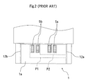
- a bill (500 Euro) P1 having a larger longitudinal dimension is fed into the apparatus without an oblique movement, but a bill (5 Euro) P2 having a smaller longitudinal dimension may be fed in an oblique direction.
- the oblique feeding of the bill P2 occurs, as shown in Fig. 2, because the bill P2 is disposed into the transport path at a position closer to one of symmetrically arranged side hopper members 12a and 12b (closer to the right side hopper member 12a in Fig.
- some of the bills put on the hopper section 1 have a deformed portion such as curl (warp) or wrinkle (folding) which is caused by a metal wheel formed on the bills.
- a deformed portion such as curl (warp) or wrinkle (folding) which is caused by a metal wheel formed on the bills.
- Such bills having a deformed portion jam at an insert port of the apparatus, which has been also a cause of a low transmission.
- the apparatus includes a stage on which bills are accumulated, side hoppers on sides of the stage, and supportive side hoppers which are pivotably mounted to the side hoppers.
- the lower parts of the supportive side hoppers and the lower parts of the side hoppers form a space having a shape which is similar to a locus of a curled bill along which the curled bill is stretched. This prevents a curled bill from being fed into the side hoppers when the curled bill is stretched.
- the present invention was made in view of the above problems, and one object of the present invention is to provide a bill discriminating and counting apparatus which is able to feed bills having different dimensions without any oblique movement, and is also able to smoothly feed bills having a curled (warped) or folded portion.
- a bill discriminating and counting apparatus comprising: a mounting platform; side hopper members symmetrically arranged on said mounting platform between which a plurality of accumulated bills having different longitudinal dimensions are filled; and a feeding mechanism for feeding said bills in serial through an insert port into a transport path, characterized in that said feeding mechanism includes a plurality of symmetrically arranged rollers which are arranged so that, when said side hopper members are separated by a distance adjusted to the largest longitudinal dimension of said bill which has the largest longitudinal dimension among said bills and also a bill which has the smallest longitudinal dimension among said bills is disposed to a position in contact with one of said side hopper members, at least a part of said roller arranged on the side opposite to that of said side hopper member in contact with said bill contacts said bill.
- said feeding mechanism comprises: a plurality of kicker rollers which are symmetrically arranged on said mounting platform for feeding said bills downstream; a plurality of feed rollers which are symmetrically arranged downstream of said kicker rollers for drawing said bills fed by said kicker rollers into said transport path; a plurality of reversing rollers disposed opposite to said feed rollers for controlling the distance between said feed rollers and said reversing rollers so that only one of said bills passes there through; a plurality of auxiliary rollers arranged opposite to said feed rollers upstream of said reversing rollers for assisting the feeding of said bills by said kicker roller; and a plurality of pinch rollers arranged opposite to said feed rollers downstream of said reversing rollers for drawing said bills, after passing through the space between said feed rollers and said reversing rollers, into said transport path, and that said kicker rollers, said feed rollers, said reversing roller
- a bill discriminating and counting apparatus comprising: a mounting platform; side hopper members symmetrically arranged on said mounting platform between which a plurality of accumulated bills are filled; and a feeding mechanism for feeding said bills in serial through an insert port into a transport path, characterized in that said feeding mechanism includes a guide member for guiding said bills fed to said insert port toward an inlet of said transport path, and said guide member has guide surfaces formed so that the opening area thereof is gradually increased toward the both ends thereof, and said guide surfaces are formed so that the opening area thereof is converged to zero from said insert port toward the inlet of said transport path.
- a bill discriminating and counting apparatus of the present invention which is configured as described above, since even when the bill, which has the smallest longitudinal dimension among the bills filled between the symmetrically arranged side hopper members, is disposed to a position where the bill contacts one of the side hopper members, each of the kicker rollers, the feed rollers, the reversing rollers, the auxiliary rollers, and the pinch rollers of the feeding mechanism which are arranged on the side opposite to that the side hopper member in contact with the bill (that is, the rollers on the left side when the bill is disposed to contact the right side hopper member) are arranged to at least partially contact the bill, the bills are fed in series into the transport path without any oblique movement. This increases the transmission of bills, and improves a bill counting work.
- the guide member at the insert port has guide surfaces formed so that the opening area thereof is gradually increased toward the both ends thereof, and said guide surfaces are formed so that the opening area thereof is converged to zero from said insert port toward the inlet of said transport path, even when a bill having deformation such as curl or wrinkle at its end is fed to the insert port, the bill smoothly recovers its flat shape without butting with a front part of the guide member. This prevents an oblique movement of a bill which has decreased the transmission, and improves a counting work of bills. Furthermore, the guide member has a simple structure with fewer components, and has a shape easy to process, resulting in a lower manufacturing cost.
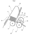
- Fig. 3 is a cross-sectional view showing main sections of a feeding mechanism included in a bill discriminating and counting apparatus according to a first embodiment of the present invention.
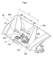
- Fig. 4 is a perspective view showing an outside of the feeding mechanism
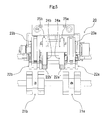
- Fig. 5 is a top plan view showing an internal structure of the feeding mechanism.
- a feeding mechanism 20 of the first embodiment is configured so that a plurality of accumulated bills P having different dimensions are filled between side hopper members 32 (a right side hopper member 32a and a left side hopper member 32b) which are symmetrically arranged on a mounting platform 31 of a hopper section 30, and are fed in series through an insert port 33 into a transport path 40.
- the feeding mechanism 20 includes a pair of kicker rollers 21 (a right side rollers 21a and a left side rollers 21b) which rotate clockwise in Fig. 3 for feeding the bills P in a direction toward the inside of the apparatus (in a direction to the right side in Fig. 3), and a pair of feed rollers 22 (a right side rollers 22a and a left side rollers 22b) arranged downstream of the kicker rollers 21 for drawing the bills P fed by the kicker rollers 21 into the transport path 40.
- the kicker rollers 21a, 21b and the feed rollers 22a, 22b are symmetrically arranged as shown in Fig. 5, respectively.
- a pair of reversing rollers 23 are symmetrically arranged to control the space between the feed rollers 22 and the reversing rollers 23 so that only one of the bills P passes there through. So, a clockwise rotation of the feed rollers 22 in Fig. 3 causes the bottom one of the bills P to pass through the feed rollers 22 and the reversing rollers 23.
- auxiliary rollers 24 Upstream of the reversing rollers 23 (on the left side in Fig. 3), a pair of auxiliary rollers 24 (a right side roller 24a and a left side roller 24b) are symmetrically arranged to oppose the feed rollers 22, and the auxiliary roller 24 are adapted to assist the feeding of the bills P by the kicker rollers 21.
- a pair of pinch rollers 25 are symmetrically arranged to oppose the feed rollers 22.
- the pinch rollers 25a, 25b are in contact with feed roller transporting sections 22a' and 22b' having a higher coefficient of friction than that of other feed roller parts 22, thereby the bills P, after passing through the space between the feed rollers 22 and the reversing rollers 23, can be drawn in the transport path 40 without fail.
- the side hopper members 32a and 32b symmetrically arranged on the mounting platform 31 are slidable in a direction shown by an arrow X - X' in synchronization with each other, and are configured to be able to optionally control the width L between the side hopper members 32a and 32b depending on the intended use.
- the first embodiment as shown in Fig.
- a bill P2 having the smallest longitudinal dimension (hereinafter, referred to as smallest bill) is disposed, between the right side hopper member 32a and the left side hopper member 32b, to a position closer to one of the side hopper members 32, that is, to a position where one edge (one shorter side) of the smallest bill P2 is in contact with the right side hopper member 32a.
- Fig. 6 is a top plan view for illustrating an arrangement of the kicker rollers 21a and 21b.
- the kicker rollers 21a and 21b are arranged so that, even when the smallest bill P2 is disposed to be in contact with the right side hopper member 32a, at least a part of the left kicker rollers 21b, that is, the central (right side) roller of left kicker rollers 21b contacts the smallest bills P2. Therefore, the kicker rollers 21a and 21b are arranged according to the following formula: B ⁇ A ⁇ 2 where B is a dimension from the right side hopper member 32a to the left edge of the rightmost roller among the left kicker rollers 21b.
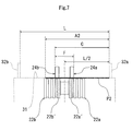
- Fig. 7 is a front view for illustrating a positional relationship between the feed rollers 22a, 22b and the auxiliary roller 24a, 24b.
- the auxiliary rollers 24a and 24b are arranged so that, even when the smallest bill P2 is disposed to be in contact with the right side hopper member 32a, the left auxiliary roller 24b contacts the smallest bills P2. Therefore, the auxiliary rollers 24a and 24b are arranged according to the following formula: C ⁇ A ⁇ 2 where C is a dimension from the right side hopper member 32a to the outer end (the left end) of the left auxiliary roller 24b.
- the auxiliary rollers 24a and 24b are arranged according to the following formula: F / 2 ⁇ A ⁇ 2 - L / 2 where F is a dimension from the outer end (the right end) of the right auxiliary roller 24a to the outer end (the left end) of the left auxiliary roller 24b. That is, the smaller space between the right auxiliary roller 24a and the left auxiliary roller 24b allows the right auxiliary roller 24a and the left auxiliary roller 24b to be arranged according to the formula (3), and to contact the smallest bills P2 wherever the smallest bill P2 is disposed between the side hopper members 32.
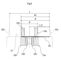
- Fig. 8 is a front view for illustrating a positional relationship between the feed rollers 22a, 22b and the reversing rollers 23a, 23b.
- the reversing rollers 23a, 23b are arranged so that, even when the smallest bill P2 is disposed to be in contact with the right side hopper member 32a, the left reversing rollers 23b contacts the smallest bills P2. Therefore, the reversing rollers 23a, 23b are arranged according to the following formula: D ⁇ A ⁇ 2 where D is a dimension from the right side hopper member 32a to the outer end (the left end) of the left reversing rollers 23b.
- the reversing rollers 23a, 23b are arranged according to the following formula: G / 2 ⁇ A ⁇ 2 - L / 2 where G is a dimension from the outer end (the right end) of the right reversing rollers 23a to the outer end (the left end) of the left reversing rollers 23b. That is, the smaller space between the right reversing roller 23a and the left reversing roller 23b allows the right reversing roller 23a and the left reversing roller 23b to be arranged according to the formula (5), and to contact the smallest bills P2 wherever the smallest bill P2 is disposed between the side hopper members 32.
- Fig. 9 is a front view for illustrating a positional relationship between the feed rollers 22a, 22b and the pinch rollers 25a, 25b.
- the pinch rollers 25a, 25b are arranged so that, even when the smallest bill P2 is disposed to be in contact with the right side hopper member 32a, the left pinch roller 25b contacts the smallest bills P2. Therefore, the pinch rollers 25a, 25b are arranged according to the following formula: E ⁇ A ⁇ 2 where E is a dimension from the right side hopper member 32a to the outer end (the left end) of the left pinch roller 25b.
- the pinch rollers 25a, 25b are arranged according to the following formula: H / 2 ⁇ A ⁇ 2 - L / 2 where H is a dimension from the outer end (the right end) of the right pinch roller 25a to the outer end (the left end) of the left pinch roller 25b. That is, the smaller space between the right pinch roller 25a and the left pinch roller 25b allows the right pinch roller 25a and the left pinch roller 25b to be arranged according to the formula (7), and to contact the smallest bills P2 wherever the smallest bill P2 is disposed between the side hopper members 32.
- auxiliary rollers 24, the reversing rollers 23, and the pinch rollers 25 are symmetrically arranged as pairs, but the present invention is not limited to the arrangement, and each type of the rollers may include a plurality of rollers to arrange on one side. In the latter case, the centermost roller among the symmetrically arranged rollers is arranged to contact the smallest bill P2.
- the kicker rollers 21, the feed rollers 22, the reversing rollers 23, the auxiliary rollers 24, and the pinch rollers 25 included in the bill feeding mechanism 20 are arranged so that, when the symmetrically arranged side hopper members 32a, 32b are separated by a distance adjusted to the longitudinal dimension A1 of the bills P1 and also the bill P2 having the smallest longitudinal dimension among the bills P is disposed to be in contact with one of the side hopper members 32, each of the right side rollers 21a, 22a, 23a, 24a, and 25a, and the left side rollers 21b, 22b, 23b, 24b, and 25b at least partially contact the bill P2.
- the plurality of roller included in the bill feeding mechanism 20 are arranged so that at least a part of the rollers arranged on the opposite side to that of the side hopper member 32 in contact with the bills P2 contacts the bills P2.
- This configuration allows the bills P filled in the hopper section 30 which have a large difference in the longitudinal dimensions like Euro bill to be fed in serial into the transport path 40 without any oblique movement. As a result, the transmission of bills is increased, and a counting work of bills is improved.
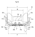
- Fig. 10 is a front view showing a hopper section included in a bill discriminating and counting apparatus according to a second embodiment of the present invention
- Fig. 11 is a side view showing main sections of the internal structure thereof.
- the hopper section 30 has the mounting platform 31 on which a plurality of the accumulated bills P are filled between the side hopper members 32 (the right side hopper member 32a and the left side hopper member 32b).
- the mounting platform 31 is provided with the kicker rollers 21 for feeding the bills P in a direction toward the insert port 33.
- a guide member 50 for guiding the fed bills P to the pinch rollers 25 which form an inlet of the transport path.
- the guide member 50 has, as shown in Fig. 10, guide surfaces 51a, 51b formed so that the opening areas 34a, 34b thereof is gradually increased toward the both ends thereof. Due to this configuration, when a bill P' among the bills P filled in the hopper section 30 which has deformation at its ends such as curl or wrinkle is fed to the insert port 33, the bill P' is prevented from butting with a front surface 52 of the guide member 50.
- the guide surfaces 51 are formed, as shown in Fig. 11, across from the insert port 33 to the pinch rollers 25. Also, the guide surfaces 51a, 51b are formed so that the opening area thereof is converged to zero toward the pinch rollers 25 which form the inlet of said transport path. This configuration allows the bills P' having the above described deformation, after passing the insert port 33, to recover its original flat shape before it reaches the pinch rollers 25, and to be smoothly fed into the transport path 40.
- the guide member 50 has the guide surfaces 51 which form an angle ⁇ of 30 degrees with the bottom surface 53 thereof, but the present invention is not limited to the configuration, and the guide member 50 may have any guide surfaces 51 which allow the bills P' having deformation to smoothly recover its original flat shape without butting with the front part 52 of the guide member 50.
- the guide member 50 includes the bottom surface 53 having a width M at the insert port 33 which can be expressed by the following formula: 2 ⁇ A ⁇ - L / 2 - J ⁇ M where A' is the longitudinal dimension of the fed bill P', and J is the width of deformation formed on the bills P'.
- the guide member 50 above the insert port 33 has guide surfaces 51a, 51b which are formed in a shape flared toward the both edges thereof to have larger opening areas 34a, 34b, and the guide surface 51a, 51b are also formed in a shape tapered from the insert port 33 toward the inlet of the transport path 40 to have opening areas 34a, 34b of zero. Due to this configuration, when a bill which has deformation at its end such as curl or wrinkle is fed to the insert port 33, the bill can smoothly recover its original flat shape without butting with a front surface 52 of the guide member 50. As a result, troubles such as oblique movements which decrease the transmission of bills can be prevented, which leads an improvement of a bill counting work.
- the present invention can be applied to a bill discriminating and counting apparatus in which bills are accepted in a hopper for discriminating denominations of the accepted bills and counting the bills so that the total amount of the received bills or the number of the received bills for each denomination is calculated, and the present invention is particularly useful to a case where bills having different dimensions or bills having deformation such as curl (warp) or folding should be smoothly fed into an apparatus.
Landscapes
- Engineering & Computer Science (AREA)
- Mechanical Engineering (AREA)
- Physics & Mathematics (AREA)
- General Physics & Mathematics (AREA)
- Sheets, Magazines, And Separation Thereof (AREA)
- Inspection Of Paper Currency And Valuable Securities (AREA)
- Delivering By Means Of Belts And Rollers (AREA)
- Feeding Of Articles By Means Other Than Belts Or Rollers (AREA)
Abstract
Description
- The present invention relates to a bill discriminating and counting apparatus for calculating the total amount of bills accepted therein or the number of bills accepted therein for each denomination, and in particular to a bill discriminating and counting apparatus which is able to feed bills having different dimensions without any oblique movement, and is also able to smoothly feed bills having a curled (warped) or folded portion.
- Conventionally a bill discriminating and counting apparatus has been known, which includes a hopper for accepting bills of mixed denominations, and the accepted bills are fed and transported one by one to discriminate the denomination and authenticity of each bill and to count the number of the bills, so that the total amount of the genuine bills or the number of the genuine bills for each denomination is calculated and displayed (see
Japanese Patent Application Laid-Open No. 2003-296801 - With reference to Fig. 1, the general structure and operation of the above apparatus will be explained. Fig. 1 is a cross-sectional view showing an internal structure of a general bill discriminating and counting apparatus.
- In Fig. 1, bills which are put on a
hopper section 1 are fed into a transport path of the bill discriminating and counting apparatus by afeeding roller 5, and are transported by a plurality oftransport rollers 6. During the transportation, the bills pass detectingsensors discriminating sensor 8 discriminates the denomination and authenticity of each of the bills. Then the bills pass another detectingsensor 7c, and are received between blades of a rotatingimpeller 9 to be sorted and accumulated in astacking section 2 when the billdiscriminating sensor 8 judges that the bill is genuine. While, when the billdiscriminating sensor 8 judges that the bill is a counterfeit bill, a solenoid 10 is operated to cause a branchingpawl 11 to move downward to send the bill to a rejectingsection 3. Thereference numeral 4 designates an operation displaying section where various settings are made for bill discriminating and counting processes. - However, in the above described bill discriminating and counting apparatus, as shown in Fig. 2, when bills having a large difference in longitudinal dimensions among denominations (for example, Euro bills) are put on a
mounting platform 1a of thehopper section 1, a bill (500 Euro) P1 having a larger longitudinal dimension is fed into the apparatus without an oblique movement, but a bill (5 Euro) P2 having a smaller longitudinal dimension may be fed in an oblique direction. The oblique feeding of the bill P2 occurs, as shown in Fig. 2, because the bill P2 is disposed into the transport path at a position closer to one of symmetrically arrangedside hopper members side hopper member 12a in Fig. 2), and the twofeeding rollers 5a and twofeeding rollers 5b which are symmetrically arranged at around the center of themounting platform 1a are not sufficiently in contact with the bill P2, that is, the leftside feeding rollers 5b are not in contact with the bill P2. The bill P2 which is obliquely fed into the transport path in this way has been a cause of a low transmission. - Moreover, some of the bills put on the
hopper section 1 have a deformed portion such as curl (warp) or wrinkle (folding) which is caused by a metal wheel formed on the bills. Such bills having a deformed portion jam at an insert port of the apparatus, which has been also a cause of a low transmission. - Thus, an apparatus in which bills having such deformation are aligned and accumulated is disclosed in
Japanese Patent Application Laid-Open No. 2003-276931 - However, the above described apparatus disclosed in
Japanese Patent Application Laid-Open No. 2003-276931 - Even if the configuration having the side hopper and the supportive side hopper is applied to an insert port of a hopper section in a bill discriminating and counting apparatus, the configuration requires a number of components, and increases the size of the apparatus, resulting in a higher manufacturing cost.
- The present invention was made in view of the above problems, and one object of the present invention is to provide a bill discriminating and counting apparatus which is able to feed bills having different dimensions without any oblique movement, and is also able to smoothly feed bills having a curled (warped) or folded portion.
- The above object of the present invention is achieved by a bill discriminating and counting apparatus, comprising: a mounting platform; side hopper members symmetrically arranged on said mounting platform between which a plurality of accumulated bills having different longitudinal dimensions are filled; and a feeding mechanism for feeding said bills in serial through an insert port into a transport path, characterized in that said feeding mechanism includes a plurality of symmetrically arranged rollers which are arranged so that, when said side hopper members are separated by a distance adjusted to the largest longitudinal dimension of said bill which has the largest longitudinal dimension among said bills and also a bill which has the smallest longitudinal dimension among said bills is disposed to a position in contact with one of said side hopper members, at least a part of said roller arranged on the side opposite to that of said side hopper member in contact with said bill contacts said bill.
- The above object of the present invention is also effectively achieved by the bill discriminating and counting apparatus, characterized in that said feeding mechanism comprises: a plurality of kicker rollers which are symmetrically arranged on said mounting platform for feeding said bills downstream; a plurality of feed rollers which are symmetrically arranged downstream of said kicker rollers for drawing said bills fed by said kicker rollers into said transport path; a plurality of reversing rollers disposed opposite to said feed rollers for controlling the distance between said feed rollers and said reversing rollers so that only one of said bills passes there through; a plurality of auxiliary rollers arranged opposite to said feed rollers upstream of said reversing rollers for assisting the feeding of said bills by said kicker roller; and a plurality of pinch rollers arranged opposite to said feed rollers downstream of said reversing rollers for drawing said bills, after passing through the space between said feed rollers and said reversing rollers, into said transport path, and that said kicker rollers, said feed rollers, said reversing rollers, said auxiliary rollers, and said pinch rollers are arranged so that, when said side hopper members are separated by a distance adjusted to the largest longitudinal dimension of a bill which has the largest longitudinal dimension among said bills and also a bill which has the smallest longitudinal dimension among said bills is disposed to a position in contact with one of said side hopper members, each of said rollers arranged on the side opposite to that of said side hopper member in contact with said bill at least partially contacts said bill.
- The above object of the present invention is also achieved by a bill discriminating and counting apparatus, comprising: a mounting platform; side hopper members symmetrically arranged on said mounting platform between which a plurality of accumulated bills are filled; and a feeding mechanism for feeding said bills in serial through an insert port into a transport path, characterized in that said feeding mechanism includes a guide member for guiding said bills fed to said insert port toward an inlet of said transport path, and said guide member has guide surfaces formed so that the opening area thereof is gradually increased toward the both ends thereof, and said guide surfaces are formed so that the opening area thereof is converged to zero from said insert port toward the inlet of said transport path.
- According to a bill discriminating and counting apparatus of the present invention which is configured as described above, since even when the bill, which has the smallest longitudinal dimension among the bills filled between the symmetrically arranged side hopper members, is disposed to a position where the bill contacts one of the side hopper members, each of the kicker rollers, the feed rollers, the reversing rollers, the auxiliary rollers, and the pinch rollers of the feeding mechanism which are arranged on the side opposite to that the side hopper member in contact with the bill (that is, the rollers on the left side when the bill is disposed to contact the right side hopper member) are arranged to at least partially contact the bill, the bills are fed in series into the transport path without any oblique movement. This increases the transmission of bills, and improves a bill counting work.
- Moreover, since the guide member at the insert port has guide surfaces formed so that the opening area thereof is gradually increased toward the both ends thereof, and said guide surfaces are formed so that the opening area thereof is converged to zero from said insert port toward the inlet of said transport path, even when a bill having deformation such as curl or wrinkle at its end is fed to the insert port, the bill smoothly recovers its flat shape without butting with a front part of the guide member. This prevents an oblique movement of a bill which has decreased the transmission, and improves a counting work of bills. Furthermore, the guide member has a simple structure with fewer components, and has a shape easy to process, resulting in a lower manufacturing cost.
-
- Fig. 1 is a cross-sectional view showing an internal structure of a general bill discriminating and counting apparatus;
- Fig. 2 is a top plan view showing a hopper section of a conventional bill discriminating and counting apparatus;
- Fig. 3 is a cross-sectional view showing main sections of a feeding mechanism included in a bill discriminating and counting apparatus according to a first embodiment of the present invention;
- Fig. 4 is a perspective view showing an outside of the feeding mechanism;
- Fig. 5 is a top plan view showing an internal structure of the feeding mechanism;
- Fig. 6 is a top plan view for illustrating a positional relationship between kicker rollers of the feeding mechanism;
- Fig. 7 is a front view for illustrating a positional relationship between a feed roller and an auxiliary roller of the feeding mechanism;
- Fig. 8 is a front view for illustrating a positional relationship between a feed roller and a reversing roller of the feeding mechanism;
- Fig. 9 is a front view for illustrating a positional relationship between a feed roller and a pinch roller of the feeding mechanism;
- Fig. 10 is a front view showing an outside of a hopper section included in an bill discriminating and counting apparatus according to a second embodiment of the present invention; and
- Fig. 11 is a side view showing main sections of the internal structure of a hopper section and feeding mechanism included in the bill discriminating and counting apparatus.
- Now, with reference to the drawings, embodiments of the present invention will be explained below.
- Fig. 3 is a cross-sectional view showing main sections of a feeding mechanism included in a bill discriminating and counting apparatus according to a first embodiment of the present invention. Fig. 4 is a perspective view showing an outside of the feeding mechanism, and Fig. 5 is a top plan view showing an internal structure of the feeding mechanism. In these Figures, a
feeding mechanism 20 of the first embodiment is configured so that a plurality of accumulated bills P having different dimensions are filled between side hopper members 32 (a rightside hopper member 32a and a leftside hopper member 32b) which are symmetrically arranged on amounting platform 31 of ahopper section 30, and are fed in series through aninsert port 33 into atransport path 40. - The
feeding mechanism 20 includes a pair of kicker rollers 21 (aright side rollers 21a and aleft side rollers 21b) which rotate clockwise in Fig. 3 for feeding the bills P in a direction toward the inside of the apparatus (in a direction to the right side in Fig. 3), and a pair of feed rollers 22 (aright side rollers 22a and aleft side rollers 22b) arranged downstream of thekicker rollers 21 for drawing the bills P fed by thekicker rollers 21 into thetransport path 40. Thekicker rollers feed rollers - Opposing to the
feed rollers 22, a pair of reversing rollers 23 (aright side roller 23a and aleft side roller 23b) are symmetrically arranged to control the space between thefeed rollers 22 and thereversing rollers 23 so that only one of the bills P passes there through. So, a clockwise rotation of thefeed rollers 22 in Fig. 3 causes the bottom one of the bills P to pass through thefeed rollers 22 and thereversing rollers 23. - Upstream of the reversing rollers 23 (on the left side in Fig. 3), a pair of auxiliary rollers 24 (a
right side roller 24a and aleft side roller 24b) are symmetrically arranged to oppose thefeed rollers 22, and theauxiliary roller 24 are adapted to assist the feeding of the bills P by thekicker rollers 21. - Downstream of the reversing rollers 23 (on the right side in Fig. 3), a pair of pinch rollers 25 (a
right side roller 25a and aleft side roller 25b) are symmetrically arranged to oppose thefeed rollers 22. Thepinch rollers roller transporting sections 22a' and 22b' having a higher coefficient of friction than that of otherfeed roller parts 22, thereby the bills P, after passing through the space between thefeed rollers 22 and thereversing rollers 23, can be drawn in thetransport path 40 without fail. - As shown in Fig. 4, the
side hopper members mounting platform 31 are slidable in a direction shown by an arrow X - X' in synchronization with each other, and are configured to be able to optionally control the width L between theside hopper members hopper section 30, the bills P1 (500 Euro: 160 mm x 82 mm) having the largest longitudinal dimension has a dimension A1 (160 mm) in the longitudinal direction, and the bills P2 (5 Euro: 120 mm x 62 mm) having the smallest longitudinal dimension has a dimension A2 (120 mm) in the longitudinal direction, and the width L between theside hopper members - Now, with reference to Fig. 6 to Fig. 9, positional relationship between the rollers included in the
feeding mechanism 20 will be explained. Herein, a case will be explained below wherein a bill P2 having the smallest longitudinal dimension (hereinafter, referred to as smallest bill) is disposed, between the rightside hopper member 32a and the leftside hopper member 32b, to a position closer to one of theside hopper members 32, that is, to a position where one edge (one shorter side) of the smallest bill P2 is in contact with the rightside hopper member 32a. - Fig. 6 is a top plan view for illustrating an arrangement of the
kicker rollers kicker rollers side hopper member 32a, at least a part of theleft kicker rollers 21b, that is, the central (right side) roller ofleft kicker rollers 21b contacts the smallest bills P2. Therefore, thekicker rollers 
where B is a dimension from the rightside hopper member 32a to the left edge of the rightmost roller among theleft kicker rollers 21b. - Fig. 7 is a front view for illustrating a positional relationship between the
feed rollers auxiliary roller auxiliary rollers side hopper member 32a, the leftauxiliary roller 24b contacts the smallest bills P2. Therefore, theauxiliary rollers 
where C is a dimension from the rightside hopper member 32a to the outer end (the left end) of the leftauxiliary roller 24b. Also, theauxiliary rollers 
where F is a dimension from the outer end (the right end) of the rightauxiliary roller 24a to the outer end (the left end) of the leftauxiliary roller 24b. That is, the smaller space between the rightauxiliary roller 24a and the leftauxiliary roller 24b allows the rightauxiliary roller 24a and the leftauxiliary roller 24b to be arranged according to the formula (3), and to contact the smallest bills P2 wherever the smallest bill P2 is disposed between theside hopper members 32. - Fig. 8 is a front view for illustrating a positional relationship between the
feed rollers rollers rollers side hopper member 32a, theleft reversing rollers 23b contacts the smallest bills P2. Therefore, the reversingrollers 
where D is a dimension from the rightside hopper member 32a to the outer end (the left end) of theleft reversing rollers 23b. Also, the reversingrollers 
where G is a dimension from the outer end (the right end) of theright reversing rollers 23a to the outer end (the left end) of theleft reversing rollers 23b. That is, the smaller space between the right reversingroller 23a and theleft reversing roller 23b allows theright reversing roller 23a and theleft reversing roller 23b to be arranged according to the formula (5), and to contact the smallest bills P2 wherever the smallest bill P2 is disposed between theside hopper members 32. - Fig. 9 is a front view for illustrating a positional relationship between the
feed rollers pinch rollers pinch rollers side hopper member 32a, theleft pinch roller 25b contacts the smallest bills P2. Therefore, thepinch rollers 
where E is a dimension from the rightside hopper member 32a to the outer end (the left end) of theleft pinch roller 25b. Also, thepinch rollers 
where H is a dimension from the outer end (the right end) of theright pinch roller 25a to the outer end (the left end) of theleft pinch roller 25b. That is, the smaller space between theright pinch roller 25a and theleft pinch roller 25b allows theright pinch roller 25a and theleft pinch roller 25b to be arranged according to the formula (7), and to contact the smallest bills P2 wherever the smallest bill P2 is disposed between theside hopper members 32. - In Fig. 6 to Fig. 9, while the case wherein the smallest bill P2 contacts the right
side hopper member 32a has been explained, since the pairs of rollers included in thefeeding mechanism 20 are symmetrically arranged respectively, the similar result is true for the case wherein the smallest bill P2 contacts the leftside hopper member 32b. - In Fig. 7 to Fig. 9, the
auxiliary rollers 24, the reversingrollers 23, and thepinch rollers 25 are symmetrically arranged as pairs, but the present invention is not limited to the arrangement, and each type of the rollers may include a plurality of rollers to arrange on one side. In the latter case, the centermost roller among the symmetrically arranged rollers is arranged to contact the smallest bill P2. - As described above, according to the first embodiment of the bill discriminating and counting apparatus of the present invention, the
kicker rollers 21, thefeed rollers 22, the reversingrollers 23, theauxiliary rollers 24, and thepinch rollers 25 included in thebill feeding mechanism 20 are arranged so that, when the symmetrically arrangedside hopper members side hopper members 32, each of theright side rollers left side rollers bill feeding mechanism 20 are arranged so that at least a part of the rollers arranged on the opposite side to that of theside hopper member 32 in contact with the bills P2 contacts the bills P2. This configuration allows the bills P filled in thehopper section 30 which have a large difference in the longitudinal dimensions like Euro bill to be fed in serial into thetransport path 40 without any oblique movement. As a result, the transmission of bills is increased, and a counting work of bills is improved. - Next, with reference to Fig. 10 and Fig. 11, a second embodiment of the present invention will be explained below. In the embodiment, the same members are designated by the same reference numbers as those in the first embodiment, and will not be explained.
- Fig. 10 is a front view showing a hopper section included in a bill discriminating and counting apparatus according to a second embodiment of the present invention, and Fig. 11 is a side view showing main sections of the internal structure thereof. As shown in Fig. 11, the
hopper section 30 has the mountingplatform 31 on which a plurality of the accumulated bills P are filled between the side hopper members 32 (the rightside hopper member 32a and the leftside hopper member 32b). The mountingplatform 31 is provided with thekicker rollers 21 for feeding the bills P in a direction toward theinsert port 33. Below theinsert port 33 is provided with thefeed rollers 22, and above of theinsert port 33 is provided with the reversingrollers 23, theauxiliary rollers 24, and thepinch rollers 25 at positions opposing to thefeed rollers 22. Thefeeding mechanism 20 including these rollers causes the bills P filled in thehopper section 30 to be fed one by one through theinsert port 33 into thetransport path 40. - Also, above the
insert port 33 is provided with aguide member 50 for guiding the fed bills P to thepinch rollers 25 which form an inlet of the transport path. Theguide member 50 has, as shown in Fig. 10,guide surfaces opening areas hopper section 30 which has deformation at its ends such as curl or wrinkle is fed to theinsert port 33, the bill P' is prevented from butting with afront surface 52 of theguide member 50. - The guide surfaces 51 are formed, as shown in Fig. 11, across from the
insert port 33 to thepinch rollers 25. Also, the guide surfaces 51a, 51b are formed so that the opening area thereof is converged to zero toward thepinch rollers 25 which form the inlet of said transport path. This configuration allows the bills P' having the above described deformation, after passing theinsert port 33, to recover its original flat shape before it reaches thepinch rollers 25, and to be smoothly fed into thetransport path 40. - In the embodiment, as shown in Fig. 10, the
guide member 50 has the guide surfaces 51 which form an angle α of 30 degrees with thebottom surface 53 thereof, but the present invention is not limited to the configuration, and theguide member 50 may have any guide surfaces 51 which allow the bills P' having deformation to smoothly recover its original flat shape without butting with thefront part 52 of theguide member 50. - Also, the
guide member 50 includes thebottom surface 53 having a width M at theinsert port 33 which can be expressed by the following formula:
where A' is the longitudinal dimension of the fed bill P', and J is the width of deformation formed on the bills P'. - As described above, according to the second embodiment of the bill discriminating and counting apparatus of the present invention, the
guide member 50 above theinsert port 33 hasguide surfaces larger opening areas guide surface insert port 33 toward the inlet of thetransport path 40 to haveopening areas insert port 33, the bill can smoothly recover its original flat shape without butting with afront surface 52 of theguide member 50. As a result, troubles such as oblique movements which decrease the transmission of bills can be prevented, which leads an improvement of a bill counting work. - While the present invention has been specifically explained, the present invention is not limited to the above explanation, and various modification can be made without departing from the scope of the present invention.
- The present invention can be applied to a bill discriminating and counting apparatus in which bills are accepted in a hopper for discriminating denominations of the accepted bills and counting the bills so that the total amount of the received bills or the number of the received bills for each denomination is calculated, and the present invention is particularly useful to a case where bills having different dimensions or bills having deformation such as curl (warp) or folding should be smoothly fed into an apparatus.
Claims (3)
- A bill discriminating and counting apparatus, comprising: a mounting platform; side hopper members symmetrically arranged on said mounting platform between which a plurality of accumulated bills having different longitudinal dimensions are filled; and a feeding mechanism for feeding said bills in serial through an insert port into a transport path, characterized in that
said feeding mechanism includes a plurality of symmetrically arranged rollers which are arranged so that, when said side hopper members are separated by a distance adjusted to the largest longitudinal dimension of the bill which has the largest longitudinal dimension among said bills and also a bill which has the smallest longitudinal dimension among said bills is disposed to a position in contact with one of said side hopper members, at least a part of said roller disposed on the side opposite to that of said side hopper member in contact with said bill contacts said bill. - A bill discriminating and counting apparatus according to claim 1, characterized in that
said feeding mechanism comprises:a plurality of kicker rollers which are symmetrically arranged on said mounting platform for feeding said bills downstream;a plurality of feed rollers which are symmetrically arranged downstream of said kicker rollers for drawing in said bills fed by said kicker rollers into said transport path;a plurality of reversing rollers disposed opposite to said feed rollers for controlling the distance between said feed rollers and said reversing rollers so that only one of said bills passes there through;a plurality of auxiliary rollers arranged opposite to said feed rollers upstream of said reversing rollers for assisting the feeding of said bills by said kicker roller; anda plurality of pinch rollers arranged opposite to said feed rollers downstream of said reversing rollers for drawing in said bills, after passing through the space between said feed rollers and said reversing rollers, into said transport path, and thatsaid kicker rollers, said feed rollers, said reversing rollers, said auxiliary rollers, and said pinch rollers are arranged so that, when said side hopper members are separated by a distance adjusted to the largest longitudinal dimension of said bill which has the largest longitudinal dimension among said bills and also a bill which has the smallest longitudinal dimension among said bills is disposed to a position in contact with one of said side hopper members, each of said rollers arranged on the side opposite to that of said side hopper member in contact with said bill at least partially contacts said bill. - A bill discriminating and counting apparatus, comprising: a mounting platform; side hopper members symmetrically arranged on said mounting platform between which a plurality of accumulated bills are filled; and a feeding mechanism for feeding said bills in serial through an insert port into a transport path, characterized in that
said feeding mechanism includes a guide member for guiding said bills fed to said insert port toward an inlet of said transport path, and said guide member has guide surfaces formed so that the opening area thereof is gradually increased toward the both ends thereof, and said guide surfaces are formed so that the opening area thereof is converged to zero from said insert port toward the inlet of said transport path.
Priority Applications (1)
| Application Number | Priority Date | Filing Date | Title |
|---|---|---|---|
| EP08165072.3A EP2009601B1 (en) | 2004-10-12 | 2004-10-12 | Bill discriminating and counting apparatus |
Applications Claiming Priority (1)
| Application Number | Priority Date | Filing Date | Title |
|---|---|---|---|
| PCT/JP2004/015340 WO2006040833A1 (en) | 2004-10-12 | 2004-10-12 | Bill identification and counting machine |
Related Child Applications (2)
| Application Number | Title | Priority Date | Filing Date |
|---|---|---|---|
| EP08165072.3A Division EP2009601B1 (en) | 2004-10-12 | 2004-10-12 | Bill discriminating and counting apparatus |
| EP08165072.3 Division-Into | 2008-09-25 |
Publications (3)
| Publication Number | Publication Date |
|---|---|
| EP1821265A1 true EP1821265A1 (en) | 2007-08-22 |
| EP1821265A4 EP1821265A4 (en) | 2008-02-20 |
| EP1821265B1 EP1821265B1 (en) | 2012-01-25 |
Family
ID=36148135
Family Applications (2)
| Application Number | Title | Priority Date | Filing Date |
|---|---|---|---|
| EP08165072.3A Expired - Lifetime EP2009601B1 (en) | 2004-10-12 | 2004-10-12 | Bill discriminating and counting apparatus |
| EP04773790A Revoked EP1821265B1 (en) | 2004-10-12 | 2004-10-12 | Bill identification and counting machine |
Family Applications Before (1)
| Application Number | Title | Priority Date | Filing Date |
|---|---|---|---|
| EP08165072.3A Expired - Lifetime EP2009601B1 (en) | 2004-10-12 | 2004-10-12 | Bill discriminating and counting apparatus |
Country Status (7)
| Country | Link |
|---|---|
| US (2) | US7806402B2 (en) |
| EP (2) | EP2009601B1 (en) |
| JP (1) | JP4833851B2 (en) |
| KR (1) | KR101156990B1 (en) |
| CN (1) | CN100565594C (en) |
| AT (1) | ATE543167T1 (en) |
| WO (1) | WO2006040833A1 (en) |
Cited By (4)
| Publication number | Priority date | Publication date | Assignee | Title |
|---|---|---|---|---|
| DE102009017411A1 (en) * | 2009-04-14 | 2010-10-21 | Giesecke & Devrient Gmbh | Device for entering one or more value documents |
| EP2378492A1 (en) * | 2010-04-13 | 2011-10-19 | Laurel Precision Machines Co., Ltd. | Banknote processing apparatus |
| WO2019113450A1 (en) | 2017-12-07 | 2019-06-13 | Crane Payment Innovations, Inc. | Open banknote path system |
| US11878883B2 (en) * | 2019-12-26 | 2024-01-23 | Seiko Epson Corporation | Medium feeding apparatus and image reading apparatus |
Families Citing this family (16)
| Publication number | Priority date | Publication date | Assignee | Title |
|---|---|---|---|---|
| KR100992078B1 (en) | 2008-01-07 | 2010-11-04 | 주식회사 메카트로 | Banknote Discharge Accelerator of Banknote Counter |
| KR100990113B1 (en) * | 2008-01-07 | 2010-10-29 | 주식회사 메카트로 | Banknote Insert of Banknote Counter |
| JP2009220938A (en) * | 2008-03-14 | 2009-10-01 | Sharp Corp | Paper feeder and image forming device |
| JP5089468B2 (en) * | 2008-04-09 | 2012-12-05 | 株式会社Pfu | Feeding device |
| JP4930463B2 (en) | 2008-07-09 | 2012-05-16 | 沖電気工業株式会社 | Media processing device |
| FR2951848B1 (en) * | 2009-10-28 | 2011-12-09 | Neopost Technologies | DEVICE FOR SELECTING IMPROVED LEVER MAIL ARTICLES. |
| CN102837840B (en) * | 2012-09-18 | 2015-10-07 | 昆山古鳌电子机械有限公司 | One has card paper money block bundling device tied note band pilot tape duct device |
| CN103803321A (en) * | 2012-11-08 | 2014-05-21 | 鸿富锦精密工业(深圳)有限公司 | Paper currency transmission structure used in paper currency sorting machine |
| JP6082256B2 (en) * | 2013-01-18 | 2017-02-15 | 株式会社Pfu | Medium supply device |
| JP6110146B2 (en) | 2013-01-18 | 2017-04-05 | 株式会社Pfu | Medium supply device |
| CN103159091B (en) * | 2013-04-03 | 2016-05-11 | 广州广电运通金融电子股份有限公司 | A kind of banknote deposting/drawing out device |
| CN103449213B (en) * | 2013-08-30 | 2016-09-28 | 湖北中烟工业有限责任公司 | A kind of cigarette packer pre-cut seal paper conveyer |
| US10866291B2 (en) * | 2014-09-12 | 2020-12-15 | Emory University | Devices and systems for MRI-guided procedures |
| CN105632023A (en) * | 2016-03-03 | 2016-06-01 | 浙江维融电子科技股份有限公司 | Longitudinal banknote counting and distinguishing machine |
| KR101965857B1 (en) * | 2017-07-24 | 2019-04-05 | 주식회사 에이텍에이피 | Media separating apparatus and financial device including the same |
| KR102855559B1 (en) * | 2023-07-24 | 2025-09-03 | 효성티앤에스 주식회사 | Automatic teller machine |
Family Cites Families (18)
| Publication number | Priority date | Publication date | Assignee | Title |
|---|---|---|---|---|
| BE567587A (en) | 1957-05-10 | |||
| US3957366A (en) | 1974-09-05 | 1976-05-18 | Xerox Corporation | Sheet feeding apparatus |
| DE2548005A1 (en) * | 1974-11-25 | 1976-05-26 | Xerox Corp | SHEET CUTTER AND FEED DEVICE |
| US3941373A (en) * | 1974-11-25 | 1976-03-02 | Xerox Corporation | Floating gate sheet separator |
| US3933350A (en) * | 1974-12-09 | 1976-01-20 | Mignano Frank J | Paper insert feeder |
| US4114870A (en) * | 1976-07-12 | 1978-09-19 | Brandt-Pra, Inc. | Document handling and counting device having guide fingers for facilitating the feeding of curled, folded and creased documents and further having improved outfeed stacker means for facilitating the neat stacking of documents of the aforementioned type |
| JPS56122747A (en) | 1980-02-27 | 1981-09-26 | Ricoh Co Ltd | Corrector for skew and lateral position of paper |
| JPS61174085A (en) * | 1985-01-28 | 1986-08-05 | 株式会社日立製作所 | Guide appartus for door of elevator |
| US4715593A (en) * | 1985-12-02 | 1987-12-29 | Godlewski Edward S | Stack-supporting bottom feed conveyor |
| DE3706834A1 (en) * | 1987-03-03 | 1988-09-15 | Nixdorf Computer Ag | DISPENSING DEVICE FOR SHEET MATERIAL |
| US5207788A (en) * | 1991-04-04 | 1993-05-04 | Cummins-Allison Corp. | Feed arrangement for currency handling machines |
| JPH06176244A (en) * | 1992-12-03 | 1994-06-24 | Sanyo Electric Co Ltd | Paper sheet processor |
| JP3560223B2 (en) * | 1998-09-17 | 2004-09-02 | 株式会社日立製作所 | Paper sheet separation and feeding device |
| US6375180B1 (en) * | 1999-05-19 | 2002-04-23 | Konica Corporation | Sheet finisher, image forming apparatus, and sheet conveyance apparatus |
| JP4369012B2 (en) * | 2000-04-24 | 2009-11-18 | グローリー株式会社 | Paper sheet processing equipment |
| JP3962584B2 (en) | 2001-01-12 | 2007-08-22 | 株式会社リコー | Image forming apparatus |
| JP2003276931A (en) * | 2002-03-20 | 2003-10-02 | Oki Electric Ind Co Ltd | Medium processor |
| JP2003296801A (en) | 2002-04-02 | 2003-10-17 | Toyo Commun Equip Co Ltd | Bill counter |
-
2004
- 2004-10-12 WO PCT/JP2004/015340 patent/WO2006040833A1/en not_active Ceased
- 2004-10-12 EP EP08165072.3A patent/EP2009601B1/en not_active Expired - Lifetime
- 2004-10-12 AT AT04773790T patent/ATE543167T1/en active
- 2004-10-12 EP EP04773790A patent/EP1821265B1/en not_active Revoked
- 2004-10-12 CN CNB2004800442177A patent/CN100565594C/en not_active Expired - Lifetime
- 2004-10-12 US US11/664,995 patent/US7806402B2/en not_active Expired - Lifetime
- 2004-10-12 JP JP2006540811A patent/JP4833851B2/en not_active Expired - Fee Related
- 2004-10-12 KR KR1020077007726A patent/KR101156990B1/en not_active Expired - Fee Related
-
2010
- 2010-08-17 US US12/858,175 patent/US8336875B2/en not_active Expired - Fee Related
Cited By (8)
| Publication number | Priority date | Publication date | Assignee | Title |
|---|---|---|---|---|
| DE102009017411A1 (en) * | 2009-04-14 | 2010-10-21 | Giesecke & Devrient Gmbh | Device for entering one or more value documents |
| US8582186B2 (en) | 2009-04-14 | 2013-11-12 | Giesecke & Devrient Gmbh | Device for inputting one or several value documents |
| EP2378492A1 (en) * | 2010-04-13 | 2011-10-19 | Laurel Precision Machines Co., Ltd. | Banknote processing apparatus |
| US8302960B2 (en) | 2010-04-13 | 2012-11-06 | Laurel Precision Machines Co., Ltd. | Banknote processing apparatus with separating and feeding portion |
| WO2019113450A1 (en) | 2017-12-07 | 2019-06-13 | Crane Payment Innovations, Inc. | Open banknote path system |
| EP3721419A4 (en) * | 2017-12-07 | 2021-12-08 | Crane Payment Innovations, Inc. | OPEN BANK NOTE ROUTE SYSTEM |
| US11475728B2 (en) | 2017-12-07 | 2022-10-18 | Crane Payment Innovations, Inc. | Open banknote path system |
| US11878883B2 (en) * | 2019-12-26 | 2024-01-23 | Seiko Epson Corporation | Medium feeding apparatus and image reading apparatus |
Also Published As
| Publication number | Publication date |
|---|---|
| ATE543167T1 (en) | 2012-02-15 |
| EP1821265B1 (en) | 2012-01-25 |
| US20090008862A1 (en) | 2009-01-08 |
| EP2009601A1 (en) | 2008-12-31 |
| EP2009601B1 (en) | 2013-12-04 |
| KR101156990B1 (en) | 2012-06-20 |
| WO2006040833A1 (en) | 2006-04-20 |
| JP4833851B2 (en) | 2011-12-07 |
| CN100565594C (en) | 2009-12-02 |
| EP1821265A4 (en) | 2008-02-20 |
| JPWO2006040833A1 (en) | 2008-05-15 |
| US7806402B2 (en) | 2010-10-05 |
| KR20070083632A (en) | 2007-08-24 |
| US8336875B2 (en) | 2012-12-25 |
| HK1111500A1 (en) | 2008-08-08 |
| CN101044515A (en) | 2007-09-26 |
| US20100308527A1 (en) | 2010-12-09 |
Similar Documents
| Publication | Publication Date | Title |
|---|---|---|
| US8336875B2 (en) | Bill discriminating and counting apparatus | |
| KR101276901B1 (en) | Machine for handling a receiving paper money | |
| JP2002137862A (en) | Bill processing device and bill processing method | |
| EP3721419B1 (en) | Open banknote path system | |
| JP3766466B2 (en) | Method for determining the number of paper sheets and paper sheet handling apparatus | |
| EP2045780A1 (en) | Device for detecting deformed coin | |
| JP5193874B2 (en) | Paper sheet counting device | |
| CN107204071A (en) | Paper gathers mechanism and bill handling device | |
| US7699313B2 (en) | Paper sheet stacking apparatus | |
| JP2009151703A (en) | Paper money processor | |
| CN104952148B (en) | Banknotes processing apparatus | |
| RU2352994C2 (en) | Denomination recognition and count device | |
| JP5176739B2 (en) | Banknote processing apparatus and money processing machine | |
| CN102542333B (en) | Paper counting device | |
| JP3594352B2 (en) | Paper handling equipment | |
| JP2018120356A (en) | Paper sheet identification device and paper sheet processing device | |
| JP2007220031A (en) | Bill handling apparatus | |
| JPS6235713B2 (en) | ||
| HK1111500B (en) | Bill identification and counting machine | |
| JPH07172610A (en) | Paper sheet separation device | |
| CN101714271A (en) | Note identifying counter | |
| JPS638160A (en) | Paper leaf switching gate | |
| JPH0725435B2 (en) | Paper transport device | |
| JPH10320609A (en) | Paper handling equipment equipped with sheet number determination means | |
| JPH02291355A (en) | Paper sheet stacking device |
Legal Events
| Date | Code | Title | Description |
|---|---|---|---|
| PUAI | Public reference made under article 153(3) epc to a published international application that has entered the european phase |
Free format text: ORIGINAL CODE: 0009012 |
|
| 17P | Request for examination filed |
Effective date: 20070426 |
|
| AK | Designated contracting states |
Kind code of ref document: A1 Designated state(s): AT BE BG CH CY CZ DE DK EE ES FI FR GB GR HU IE IT LI LU MC NL PL PT RO SE SI SK TR |
|
| RIC1 | Information provided on ipc code assigned before grant |
Ipc: G07D 11/00 20060101ALI20071004BHEP Ipc: G07D 9/04 20060101AFI20060427BHEP |
|
| DAX | Request for extension of the european patent (deleted) | ||
| A4 | Supplementary search report drawn up and despatched |
Effective date: 20080123 |
|
| 17Q | First examination report despatched |
Effective date: 20080523 |
|
| GRAP | Despatch of communication of intention to grant a patent |
Free format text: ORIGINAL CODE: EPIDOSNIGR1 |
|
| GRAS | Grant fee paid |
Free format text: ORIGINAL CODE: EPIDOSNIGR3 |
|
| GRAA | (expected) grant |
Free format text: ORIGINAL CODE: 0009210 |
|
| AK | Designated contracting states |
Kind code of ref document: B1 Designated state(s): AT BE BG CH CY CZ DE DK EE ES FI FR GB GR HU IE IT LI LU MC NL PL PT RO SE SI SK TR |
|
| REG | Reference to a national code |
Ref country code: GB Ref legal event code: FG4D |
|
| REG | Reference to a national code |
Ref country code: CH Ref legal event code: EP |
|
| REG | Reference to a national code |
Ref country code: AT Ref legal event code: REF Ref document number: 543167 Country of ref document: AT Kind code of ref document: T Effective date: 20120215 |
|
| REG | Reference to a national code |
Ref country code: IE Ref legal event code: FG4D |
|
| REG | Reference to a national code |
Ref country code: DE Ref legal event code: R096 Ref document number: 602004036303 Country of ref document: DE Effective date: 20120322 |
|
| REG | Reference to a national code |
Ref country code: NL Ref legal event code: VDEP Effective date: 20120125 |
|
| PG25 | Lapsed in a contracting state [announced via postgrant information from national office to epo] |
Ref country code: BG Free format text: LAPSE BECAUSE OF FAILURE TO SUBMIT A TRANSLATION OF THE DESCRIPTION OR TO PAY THE FEE WITHIN THE PRESCRIBED TIME-LIMIT Effective date: 20120425 Ref country code: NL Free format text: LAPSE BECAUSE OF FAILURE TO SUBMIT A TRANSLATION OF THE DESCRIPTION OR TO PAY THE FEE WITHIN THE PRESCRIBED TIME-LIMIT Effective date: 20120125 Ref country code: BE Free format text: LAPSE BECAUSE OF FAILURE TO SUBMIT A TRANSLATION OF THE DESCRIPTION OR TO PAY THE FEE WITHIN THE PRESCRIBED TIME-LIMIT Effective date: 20120125 |
|
| PG25 | Lapsed in a contracting state [announced via postgrant information from national office to epo] |
Ref country code: PT Free format text: LAPSE BECAUSE OF FAILURE TO SUBMIT A TRANSLATION OF THE DESCRIPTION OR TO PAY THE FEE WITHIN THE PRESCRIBED TIME-LIMIT Effective date: 20120525 Ref country code: PL Free format text: LAPSE BECAUSE OF FAILURE TO SUBMIT A TRANSLATION OF THE DESCRIPTION OR TO PAY THE FEE WITHIN THE PRESCRIBED TIME-LIMIT Effective date: 20120125 Ref country code: GR Free format text: LAPSE BECAUSE OF FAILURE TO SUBMIT A TRANSLATION OF THE DESCRIPTION OR TO PAY THE FEE WITHIN THE PRESCRIBED TIME-LIMIT Effective date: 20120426 Ref country code: FI Free format text: LAPSE BECAUSE OF FAILURE TO SUBMIT A TRANSLATION OF THE DESCRIPTION OR TO PAY THE FEE WITHIN THE PRESCRIBED TIME-LIMIT Effective date: 20120125 |
|
| REG | Reference to a national code |
Ref country code: AT Ref legal event code: MK05 Ref document number: 543167 Country of ref document: AT Kind code of ref document: T Effective date: 20120125 |
|
| PG25 | Lapsed in a contracting state [announced via postgrant information from national office to epo] |
Ref country code: CY Free format text: LAPSE BECAUSE OF FAILURE TO SUBMIT A TRANSLATION OF THE DESCRIPTION OR TO PAY THE FEE WITHIN THE PRESCRIBED TIME-LIMIT Effective date: 20120125 |
|
| PG25 | Lapsed in a contracting state [announced via postgrant information from national office to epo] |
Ref country code: RO Free format text: LAPSE BECAUSE OF FAILURE TO SUBMIT A TRANSLATION OF THE DESCRIPTION OR TO PAY THE FEE WITHIN THE PRESCRIBED TIME-LIMIT Effective date: 20120125 Ref country code: CZ Free format text: LAPSE BECAUSE OF FAILURE TO SUBMIT A TRANSLATION OF THE DESCRIPTION OR TO PAY THE FEE WITHIN THE PRESCRIBED TIME-LIMIT Effective date: 20120125 Ref country code: DK Free format text: LAPSE BECAUSE OF FAILURE TO SUBMIT A TRANSLATION OF THE DESCRIPTION OR TO PAY THE FEE WITHIN THE PRESCRIBED TIME-LIMIT Effective date: 20120125 Ref country code: SI Free format text: LAPSE BECAUSE OF FAILURE TO SUBMIT A TRANSLATION OF THE DESCRIPTION OR TO PAY THE FEE WITHIN THE PRESCRIBED TIME-LIMIT Effective date: 20120125 Ref country code: SE Free format text: LAPSE BECAUSE OF FAILURE TO SUBMIT A TRANSLATION OF THE DESCRIPTION OR TO PAY THE FEE WITHIN THE PRESCRIBED TIME-LIMIT Effective date: 20120125 Ref country code: EE Free format text: LAPSE BECAUSE OF FAILURE TO SUBMIT A TRANSLATION OF THE DESCRIPTION OR TO PAY THE FEE WITHIN THE PRESCRIBED TIME-LIMIT Effective date: 20120125 |
|
| PLBI | Opposition filed |
Free format text: ORIGINAL CODE: 0009260 |
|
| PG25 | Lapsed in a contracting state [announced via postgrant information from national office to epo] |
Ref country code: SK Free format text: LAPSE BECAUSE OF FAILURE TO SUBMIT A TRANSLATION OF THE DESCRIPTION OR TO PAY THE FEE WITHIN THE PRESCRIBED TIME-LIMIT Effective date: 20120125 Ref country code: IT Free format text: LAPSE BECAUSE OF FAILURE TO SUBMIT A TRANSLATION OF THE DESCRIPTION OR TO PAY THE FEE WITHIN THE PRESCRIBED TIME-LIMIT Effective date: 20120125 |
|
| PLAX | Notice of opposition and request to file observation + time limit sent |
Free format text: ORIGINAL CODE: EPIDOSNOBS2 |
|
| 26 | Opposition filed |
Opponent name: GIESECKE & DEVRIENT GMBH Effective date: 20121025 |
|
| PG25 | Lapsed in a contracting state [announced via postgrant information from national office to epo] |
Ref country code: AT Free format text: LAPSE BECAUSE OF FAILURE TO SUBMIT A TRANSLATION OF THE DESCRIPTION OR TO PAY THE FEE WITHIN THE PRESCRIBED TIME-LIMIT Effective date: 20120125 |
|
| REG | Reference to a national code |
Ref country code: DE Ref legal event code: R026 Ref document number: 602004036303 Country of ref document: DE Effective date: 20121025 |
|
| PLBB | Reply of patent proprietor to notice(s) of opposition received |
Free format text: ORIGINAL CODE: EPIDOSNOBS3 |
|
| PG25 | Lapsed in a contracting state [announced via postgrant information from national office to epo] |
Ref country code: ES Free format text: LAPSE BECAUSE OF FAILURE TO SUBMIT A TRANSLATION OF THE DESCRIPTION OR TO PAY THE FEE WITHIN THE PRESCRIBED TIME-LIMIT Effective date: 20120506 |
|
| PG25 | Lapsed in a contracting state [announced via postgrant information from national office to epo] |
Ref country code: MC Free format text: LAPSE BECAUSE OF NON-PAYMENT OF DUE FEES Effective date: 20121031 |
|
| REG | Reference to a national code |
Ref country code: CH Ref legal event code: PL |
|
| GBPC | Gb: european patent ceased through non-payment of renewal fee |
Effective date: 20121012 |
|
| REG | Reference to a national code |
Ref country code: IE Ref legal event code: MM4A |
|
| PG25 | Lapsed in a contracting state [announced via postgrant information from national office to epo] |
Ref country code: IE Free format text: LAPSE BECAUSE OF NON-PAYMENT OF DUE FEES Effective date: 20121012 Ref country code: GB Free format text: LAPSE BECAUSE OF NON-PAYMENT OF DUE FEES Effective date: 20121012 Ref country code: CH Free format text: LAPSE BECAUSE OF NON-PAYMENT OF DUE FEES Effective date: 20121031 Ref country code: LI Free format text: LAPSE BECAUSE OF NON-PAYMENT OF DUE FEES Effective date: 20121031 |
|
| PG25 | Lapsed in a contracting state [announced via postgrant information from national office to epo] |
Ref country code: LU Free format text: LAPSE BECAUSE OF NON-PAYMENT OF DUE FEES Effective date: 20121012 |
|
| PG25 | Lapsed in a contracting state [announced via postgrant information from national office to epo] |
Ref country code: HU Free format text: LAPSE BECAUSE OF FAILURE TO SUBMIT A TRANSLATION OF THE DESCRIPTION OR TO PAY THE FEE WITHIN THE PRESCRIBED TIME-LIMIT Effective date: 20041012 |
|
| REG | Reference to a national code |
Ref country code: DE Ref legal event code: R064 Ref document number: 602004036303 Country of ref document: DE Ref country code: DE Ref legal event code: R103 Ref document number: 602004036303 Country of ref document: DE |
|
| PGFP | Annual fee paid to national office [announced via postgrant information from national office to epo] |
Ref country code: FR Payment date: 20141022 Year of fee payment: 11 Ref country code: DE Payment date: 20141022 Year of fee payment: 11 |
|
| RDAF | Communication despatched that patent is revoked |
Free format text: ORIGINAL CODE: EPIDOSNREV1 |
|
| RDAG | Patent revoked |
Free format text: ORIGINAL CODE: 0009271 |
|
| STAA | Information on the status of an ep patent application or granted ep patent |
Free format text: STATUS: PATENT REVOKED |
|
| 27W | Patent revoked |
Effective date: 20150120 |
|
| PGFP | Annual fee paid to national office [announced via postgrant information from national office to epo] |
Ref country code: TR Payment date: 20131012 Year of fee payment: 10 |
|
| REG | Reference to a national code |
Ref country code: DE Ref legal event code: R107 Ref document number: 602004036303 Country of ref document: DE |