EP1821027B1 - Support pour dispositif de visualisation - Google Patents
Support pour dispositif de visualisation Download PDFInfo
- Publication number
- EP1821027B1 EP1821027B1 EP07290170.5A EP07290170A EP1821027B1 EP 1821027 B1 EP1821027 B1 EP 1821027B1 EP 07290170 A EP07290170 A EP 07290170A EP 1821027 B1 EP1821027 B1 EP 1821027B1
- Authority
- EP
- European Patent Office
- Prior art keywords
- display device
- supporting
- hinge
- sliding portion
- supporting portion
- Prior art date
- Legal status (The legal status is an assumption and is not a legal conclusion. Google has not performed a legal analysis and makes no representation as to the accuracy of the status listed.)
- Active
Links
- 230000007246 mechanism Effects 0.000 claims description 13
- 230000008859 change Effects 0.000 description 2
- 230000004048 modification Effects 0.000 description 2
- 238000012986 modification Methods 0.000 description 2
- 230000008878 coupling Effects 0.000 description 1
- 238000010168 coupling process Methods 0.000 description 1
- 238000005859 coupling reaction Methods 0.000 description 1
- 230000005484 gravity Effects 0.000 description 1
- 238000000034 method Methods 0.000 description 1
- 230000008569 process Effects 0.000 description 1
Images


Classifications
-
- A—HUMAN NECESSITIES
- A01—AGRICULTURE; FORESTRY; ANIMAL HUSBANDRY; HUNTING; TRAPPING; FISHING
- A01G—HORTICULTURE; CULTIVATION OF VEGETABLES, FLOWERS, RICE, FRUIT, VINES, HOPS OR SEAWEED; FORESTRY; WATERING
- A01G31/00—Soilless cultivation, e.g. hydroponics
- A01G31/02—Special apparatus therefor
-
- F—MECHANICAL ENGINEERING; LIGHTING; HEATING; WEAPONS; BLASTING
- F16—ENGINEERING ELEMENTS AND UNITS; GENERAL MEASURES FOR PRODUCING AND MAINTAINING EFFECTIVE FUNCTIONING OF MACHINES OR INSTALLATIONS; THERMAL INSULATION IN GENERAL
- F16M—FRAMES, CASINGS OR BEDS OF ENGINES, MACHINES OR APPARATUS, NOT SPECIFIC TO ENGINES, MACHINES OR APPARATUS PROVIDED FOR ELSEWHERE; STANDS; SUPPORTS
- F16M11/00—Stands or trestles as supports for apparatus or articles placed thereon ; Stands for scientific apparatus such as gravitational force meters
- F16M11/20—Undercarriages with or without wheels
- F16M11/24—Undercarriages with or without wheels changeable in height or length of legs, also for transport only, e.g. by means of tubes screwed into each other
-
- A—HUMAN NECESSITIES
- A01—AGRICULTURE; FORESTRY; ANIMAL HUSBANDRY; HUNTING; TRAPPING; FISHING
- A01G—HORTICULTURE; CULTIVATION OF VEGETABLES, FLOWERS, RICE, FRUIT, VINES, HOPS OR SEAWEED; FORESTRY; WATERING
- A01G9/00—Cultivation in receptacles, forcing-frames or greenhouses; Edging for beds, lawn or the like
- A01G9/02—Receptacles, e.g. flower-pots or boxes; Glasses for cultivating flowers
-
- F—MECHANICAL ENGINEERING; LIGHTING; HEATING; WEAPONS; BLASTING
- F16—ENGINEERING ELEMENTS AND UNITS; GENERAL MEASURES FOR PRODUCING AND MAINTAINING EFFECTIVE FUNCTIONING OF MACHINES OR INSTALLATIONS; THERMAL INSULATION IN GENERAL
- F16M—FRAMES, CASINGS OR BEDS OF ENGINES, MACHINES OR APPARATUS, NOT SPECIFIC TO ENGINES, MACHINES OR APPARATUS PROVIDED FOR ELSEWHERE; STANDS; SUPPORTS
- F16M11/00—Stands or trestles as supports for apparatus or articles placed thereon ; Stands for scientific apparatus such as gravitational force meters
- F16M11/02—Heads
- F16M11/04—Means for attachment of apparatus; Means allowing adjustment of the apparatus relatively to the stand
- F16M11/06—Means for attachment of apparatus; Means allowing adjustment of the apparatus relatively to the stand allowing pivoting
- F16M11/10—Means for attachment of apparatus; Means allowing adjustment of the apparatus relatively to the stand allowing pivoting around a horizontal axis
-
- F—MECHANICAL ENGINEERING; LIGHTING; HEATING; WEAPONS; BLASTING
- F16—ENGINEERING ELEMENTS AND UNITS; GENERAL MEASURES FOR PRODUCING AND MAINTAINING EFFECTIVE FUNCTIONING OF MACHINES OR INSTALLATIONS; THERMAL INSULATION IN GENERAL
- F16M—FRAMES, CASINGS OR BEDS OF ENGINES, MACHINES OR APPARATUS, NOT SPECIFIC TO ENGINES, MACHINES OR APPARATUS PROVIDED FOR ELSEWHERE; STANDS; SUPPORTS
- F16M11/00—Stands or trestles as supports for apparatus or articles placed thereon ; Stands for scientific apparatus such as gravitational force meters
- F16M11/20—Undercarriages with or without wheels
- F16M11/2007—Undercarriages with or without wheels comprising means allowing pivoting adjustment
- F16M11/2021—Undercarriages with or without wheels comprising means allowing pivoting adjustment around a horizontal axis
-
- F—MECHANICAL ENGINEERING; LIGHTING; HEATING; WEAPONS; BLASTING
- F16—ENGINEERING ELEMENTS AND UNITS; GENERAL MEASURES FOR PRODUCING AND MAINTAINING EFFECTIVE FUNCTIONING OF MACHINES OR INSTALLATIONS; THERMAL INSULATION IN GENERAL
- F16M—FRAMES, CASINGS OR BEDS OF ENGINES, MACHINES OR APPARATUS, NOT SPECIFIC TO ENGINES, MACHINES OR APPARATUS PROVIDED FOR ELSEWHERE; STANDS; SUPPORTS
- F16M2200/00—Details of stands or supports
- F16M2200/04—Balancing means
- F16M2200/044—Balancing means for balancing rotational movement of the undercarriage
-
- Y—GENERAL TAGGING OF NEW TECHNOLOGICAL DEVELOPMENTS; GENERAL TAGGING OF CROSS-SECTIONAL TECHNOLOGIES SPANNING OVER SEVERAL SECTIONS OF THE IPC; TECHNICAL SUBJECTS COVERED BY FORMER USPC CROSS-REFERENCE ART COLLECTIONS [XRACs] AND DIGESTS
- Y02—TECHNOLOGIES OR APPLICATIONS FOR MITIGATION OR ADAPTATION AGAINST CLIMATE CHANGE
- Y02P—CLIMATE CHANGE MITIGATION TECHNOLOGIES IN THE PRODUCTION OR PROCESSING OF GOODS
- Y02P60/00—Technologies relating to agriculture, livestock or agroalimentary industries
- Y02P60/20—Reduction of greenhouse gas [GHG] emissions in agriculture, e.g. CO2
- Y02P60/21—Dinitrogen oxide [N2O], e.g. using aquaponics, hydroponics or efficiency measures
-
- Y—GENERAL TAGGING OF NEW TECHNOLOGICAL DEVELOPMENTS; GENERAL TAGGING OF CROSS-SECTIONAL TECHNOLOGIES SPANNING OVER SEVERAL SECTIONS OF THE IPC; TECHNICAL SUBJECTS COVERED BY FORMER USPC CROSS-REFERENCE ART COLLECTIONS [XRACs] AND DIGESTS
- Y10—TECHNICAL SUBJECTS COVERED BY FORMER USPC
- Y10S—TECHNICAL SUBJECTS COVERED BY FORMER USPC CROSS-REFERENCE ART COLLECTIONS [XRACs] AND DIGESTS
- Y10S248/00—Supports
- Y10S248/917—Video display screen support
- Y10S248/919—Adjustably orientable video screen support
Definitions
- the present invention relates to a stand for a display device, and more particularly, to a stand for a display device that allows the display device to be conveniently adjusted to any one of a variety of positions desired by a user. Still more particularly, the stand for a display device has a wide height adjusting range.
- Monitors are representative examples of display devices, and are capable of being adjusted to a variety of positions to suit users' preferences.
- stands with quadric crank mechanism to conveniently adjust angles of display devices are provided in the related art.
- a stand for a display device employing the quadric crank mechanism structure allows the tilt angle of the display device to remain unchanged when the position of the display device is altered, thereby increasing the level of user convenience.
- the process of adjusting the position of the display device can only be performed by changing the center of gravity of the stand by pivoting the stand. Therefore, adjusting the position of the display device is limited to pivoting the display device about the base of the stand.
- JP 2004 333744 A and WO 2004/079699 A disclose display apparatus allowing the sliding of the display upward and downward, as well as some means allowing tilting of the display.
- US 2006/0000956 A1 discloses a display apparatus according to the preamble of claim 1.
- the present invention is directed to a stand for a display device that substantially obviates one or more problems due to limitations and disadvantages of the related art.
- An object of the present invention is to provide a stand for a display device capable of adjusting the height of the display device in various ways, and facilitating the adjustment of the display device's position to increase user convenience.
- Another object of the present invention is to provide a stand for a display device capable of raising the display device higher than in the related art, further increasing user convenience.
- a further object of the present invention is to provide an inexpensive stand for a display device capable of changing and adjusting the position of the display device in various ways.
- the stand of the display device according to the present invention is capable of adjusting the position of the display device in a variety of ways to suit a user's requirements, and prevents the tilt angle of the display device from changing while a user adjusts the position of the display device.
- the level of user convenience increases.
- the range in which the height of the display device can be adjusted is increased.
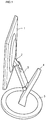
- Fig. 1 is a perspective view of a display device stand according to the present invention.
- a stand includes a display device 1 mounted thereon, a rear fixing portion 2 fixed to the rear of the display device 1, a sliding portion 3 extending approximately downward from the rear fixing portion 2, a supporting portion 4 for supporting the lower end of the sliding portion 3 and guiding the movement of the sliding portion 3 in a downward direction, and a base 5 supporting the lower end of the supporting portion 4 and supporting the display device 1 on a flat surface.
- the connecting points allow each of the members to which they are connected to pivot. Because of their ability to pivot on the hinges, the members may be collectively manipulated by a user to conveniently achieve a desired position of the display device.
- a quadric crank mechanism structure is provided inside the sliding portion 3, when the sliding portion 3 is pivoted, the tilt angle of the display device 1 is maintained. Through this adjustment, a user can conveniently adjust the height of the display device 1 while maintaining the original tilt angle of the display device 1.
- the lower end of the sliding portion 3 While the lower end of the sliding portion 3 is supported by the supporting portion 4, the lower end is capable of being slid along the extended length of the supporting portion 4. Therefore, when a user wishes to adjust the height of the display device 1, the user may move the sliding portion 3 vertically along the supporting portion 4 to conveniently adjust the height of the display device 1.
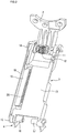
- Fig. 2 is a perspective view of a sliding portion according to the present invention
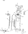
- Fig. 3 is an exploded perspective view of a sliding portion according to the present invention.
- the sliding portion 3 includes a first connecting portion connecting an upper end of the sliding portion 3 to the rear fixing portion 2, a second connecting portion connecting the lower end of the sliding portion 3 to the supporting portion 4, and a link portion connecting the first connecting portion to the second connecting portion.
- the link portion includes a main link 13 linking the first connecting portion to the second connecting portion and imparting a predetermined connecting force therebetween, and an auxiliary link consisting of auxiliary link bars 18 and 19 disposed at one side of the main link 13 and acting as a quadric crank mechanism.
- the upper ends of the auxiliary link bars 18 and 19 act as the pivoting center of the link and are connected at respectively different and eccentric dispositions to the center of rotation of a link hinge 14.
- the lower portion of the auxiliary link bars 18 and 19 are connected at respectively different and eccentric dispositions to the center of rotation of a supporting hinge 15.
- the auxiliary link bars 18 and 19, the link hinge 14 and the supporting hinge 15 may function as a quadric crank mechanism.
- the quadric crank mechanism provides a parallelogram structure, wherein when one edge is fixed and the edge opposite thereto is moved, the opposite edge moves parallelly with the one edge.
- this characteristic of a quadric crank mechanism can maintain the same tilt angle of the display device 1 when the sliding portion 3 is pivoted.
- the first connecting portion includes a hinge spring member 12 provided with a first hinge axis 21 formed at the lower end of the rear fixing portion 2 and a second hinge axis 22.
- the first hinge axis 21 and a hinge spring member 25 allow the first connecting portion to perform two types of pivoting operations.
- the first hinge axis 21 is guided by a first hinge receiving portion 23 formed on the upper portion of the main link 13, and is covered and supported by the hinge coupling portion 11. Therefore, the first hinge axis 21 can rotate while being guided by the first hinge receiving portion 23.
- the second hinge axis 22 is coupled to the link hinge 14 through a second hinge receiving portion 24.
- Two members that are capable of rotating with respect to one another are provided inside the hinge spring member 12. The two members are connected through the hinge spring 25. One of the two members is fixed to the second hinge axis 22 and rotates together with the link hinge 14. The other of the two members is fixed to the first hinge axis 21 and rotates together with the rear fixing portion 2.
- a washer or other member for providing friction is provided within the hinge spring member 12. The friction provided by the washer or other friction providing member between the two members inside the hinge spring member 12 is greater than the friction provided between the first hinge axis 21 and the first hinge receiving portion 23.
- the link hinge 14 of the quadric crank mechanism rotates about the supporting hinge 15.
- the link hinge 14 does not rotate due to the operation of the quadric crank mechanism, and performs only orbital movement about the supporting hinge 15.
- the second hinge axis 22 fixedly connected to the link hinge 14 also moves only in an orbiting fashion.
- the friction provided by the washer or other friction providing member between the two inner members in the hinge spring member 12 is greater than the friction provided between the first hinge axis 21 and the first hinge receiving portion 23. Therefore, the two members inside the hinge spring member 12 do not rotate relative to each other, and the hinge spring member 12 rotates together with the first hinge axis 21. Instead, rotation occurs between the first hinge axis 21 and the first hinge receiving portion 23, so that the main link 13 and the rear fixing portion 2 rotate differently. Thus, the display device 1 fixed to the rear fixing portion 2 rotates with respect to the main link 13.
- This rotation causes the tilt angle of the display device 1 to remain the same throughout a pivoting of the sliding portion 3 at a lower end thereof. Therefore, the user can always view the display device 1 at the same tilt angle.
- the second connecting portion is a component formed between the sliding portion 3 and the supporting portion 4, and includes a first supporting axis 27, a supporting hinge 15 inserted sequentially in the first supporting axis 27, a supporting portion 4, a lower portion of the main link 13, and a first friction portion 16.
- the first friction portion 16 is fixed with respect to the first supporting axis 27. Furthermore, at least one side thereof contacts the lower surface of the main link 13 and provides force pressing the main link 13 in an upward direction when the main link 13 rotates downward. This also applies to the second friction member 17.
- the first friction member 16 and the second friction member 17 are able to provide sufficient restoring force in any direction, when the display device 1 moves upward or downward due to the wound directions being different with respect to the first supporting axis 27.
- the first supporting axis 27 is inserted so that is cannot rotate with respect to the supporting hinge 15.
- the first supporting axis 27 that is inserted in the supporting hinge 15 may have a portion thereof formed in a non-circular shape.
- the first supporting axis 27 is fixed with respect to the first friction portion 16.
- the contacting region between the supporting portion and the first supporting axis 27 is supported by a first frictional force, and a predetermined second frictional force supports the contacting region between the lower end of the main link 13 and the first supporting axis 27.
- the first frictional force is made to be greater than the second frictional force. Therefore, under normal conditions, when an external force is applied to the display device 1 to rotate the main link 13, the first supporting axis 27 and the lower end of the main link 13 rotate against each other. In this case, the tilt angle of the display device 1 is maintained while the height of the display device 1 is adjusted.
- An elastic member 26 is connected between the second supporting link 19 and the main link 13, so that when a user pivots the main link 13, the elastic member 26 exerts a force in a predetermined direction against the main link 13.
- the auxiliary link 19 is connected at an eccentric disposition to the center of the rotating axis of the main link 13, so that the elastic member 26 expands and generates elasticity when the main link 13 is rotated.
- This elasticity is a force for returning the main link 13 and the auxiliary link 19 to their original positions.
- the deadweight of the display device 1 may be supported by means of the force.
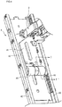
- Fig. 4 is a frontal perspective view of a supporting portion according to the present invention
- Fig. 5 is a sectional view of the supporting portion in Fig. 4 taken along line I-I'.
- the supporting portion 4 includes a guide panel 42 forming a frame thereof, a slide panel 41 along which the guide panel 42 moves in an extending direction, and a plate spring 45 for supporting the movement of the slide panel 41 with the guide panel 42 in a fixed state.
- a guide protrusion 44 is formed on a side of the slide panel 41, and an extending slot 43 is formed at the location of the guide panel 42 opposite to the guide protrusion 44.
- the supporting portion 4 in the above structure will now be described.
- the slide panel 41 pushes the plate spring 45 to unwind the plate spring 45.
- the plate spring 45 provides drag preventing the slide panel 41 from descending, so that the deadweight of the display device 1 can be conveniently raised in an upward direction.
- friction is applied to the plate spring 45 so that when the slide panel 41 attains a predetermined height, the display device 1 is stably supported.
- one end of the plate spring 45 is fixed to the guide panel 42, and the other end is wound at a predetermined curvature and put in contact with the slide panel 41.
- the guide protrusion 44 is able to move only within the extending slot 43, the vertical movement of the slide panel 41 is guided by the guide panel 42.
- the top and bottom ends of the guide panel may form a predetermined stopper.
- Figs. 6 through 8 are side views for describing operating modes of a stand according to the present invention, where Fig. 6 shows an operating mode in which the tilt angle of the display device is maintained while moving the display device vertically.
- the sliding portion pivots about the second connecting portion connecting the sliding portion 3 and the supporting portion 4.
- the quadric crank mechanism provided within the sliding portion 3 maintains the tilt angle of the display device 1 in its original position.
- This operational mode may be used in order to retain the viewing angle at which a user views the display device while moving the display device forward or backward.
- Fig. 7 shows an operating mode in which a sliding portion moves vertically along a supporting portion.
- the plate spring 45 supports the deadweight of the display device 1
- a user may adjust the height of the display device 1 by raising or lowering the same along an extending direction of the supporting portion 4.
- the display device 1 may be adjusted to a height greater than in the related art.
- Fig. 8 shows an operating mode in which the display device itself is pivoted. Referring to Fig. 8 , because the two members provided within the hinge spring member 12 are rotated, the angle at which a user views the display device may be tilted.
- the viewing angle of the display device 1 may be adjusted with more precision and accuracy, the viewing angle of the display device can be adjusted to an angle at which the picture is clearest.
- FIG. 6 through 8 Each operating mode shown in Figs. 6 through 8 may be performed separately or in combination.
- the height and tilt angle adjustments of the display device according to the present invention allow for a wide range of adjustments, so that the position of the display device can be easily adjusted, providing users with increased convenience.
- the structure of the display device is made simple, a wide assortment of operating modes are possible.
- the product can be inexpensively manufactured.
Landscapes
- Engineering & Computer Science (AREA)
- General Engineering & Computer Science (AREA)
- Mechanical Engineering (AREA)
- Life Sciences & Earth Sciences (AREA)
- Environmental Sciences (AREA)
- Devices For Indicating Variable Information By Combining Individual Elements (AREA)
Claims (11)
- Système comprenant un dispositif d'affichage et un support pour le dispositif d'affichage, le support comprenant :une portion coulissante (3) s'étendant vers une surface arrière du dispositif d'affichage (1) et supportée à une extrémité de celle-ci sur le dispositif d'affichage (1) ;une portion de support (4) pour supporter de façon coulissante la portion coulissante (3) ; etune base (5) pour supporter la portion de support, la base (5) dressant la portion de support (4),dans lequel la portion de support (4) comprend :un panneau coulissant (41) auquel une extrémité inférieure de la portion coulissante (3) est couplée ;un panneau de guidage (42) le long duquel le panneau coulissant (41) est guidé et se déplace dans une direction d'extension de la portion de support (4); etun ressort (45) apte à s'expanser et se contracter alors qu'il touche le panneau coulissant (41), et ayant au moins une extrémité de celui-ci fixée au panneau de guidage (42), et fournissant une traînée empêchant le panneau coulissant (41) de descendre de sorte que le poids mort du dispositif d'affichage (1) puisse être facilement relevé dans une direction vers le haut, et la portion coulissante (3) et la portion de support (4) sont formées pour s'étendre dans des directions mutuellement différentes,caractérisé en ce que la portion coulissante (3) comprend un mécanisme à manivelle quadratique pour maintenir un angle d'inclinaison du dispositif d'affichage (1) lorsqu'une force inférieure à un niveau prédéterminé est appliquée au dispositif d'affichage (1), ledit mécanisme à manivelle quadratique comprenant :une articulation de bielle (14) fournissant une liaison d'articulation entre la portion coulissante (3) et le dispositif d'affichage (1) ;une articulation de support (15) fournissant une liaison d'articulation entre la portion coulissante (3) et la portion de support (4) ;une paire de liaisons auxiliaires (18, 19) reliant de manière excentrée l'articulation de bielle (14) à l'articulation de support (15) ; etune liaison principale (13) reliant l'articulation de bielle (14) et l'articulation de support (15),dans lequel un premier axe de support (27) est inséré de façon à ne pas pouvoir tourner par rapport à l'articulation de support (15),dans lequel une première portion de frottement (16) et une seconde portion de frottement (17) sont fixées par rapport au premier axe de support (27), et au moins un côté de celui-ci touche la surface inférieure du lien principal (13), et fournit une force poussant la liaison principale (13) dans une direction vers le haut lorsque la liaison principal (13) tourne vers le bas,dans lequel la première portion de frottement (16) et la seconde portion de frottement (17) sont aptes à fournir une force de restauration suffisante dans une direction quelconque, lorsque le dispositif d'affichage (1) se déplace vers le haut ou le bas en raison des directions d'enroulement différentes par rapport au premier axe de support (27).
- Système selon la revendication 1, dans lequel la portion coulissante (3) et une portion de raccordement du dispositif d'affichage (1) sont respectivement aptes à tourner.
- Système selon la revendication 1, dans lequel une extrémité inférieure de la portion coulissante (3) est supportée par une force de frottement contre la portion de support (4).
- Système selon la revendication 1, dans lequel la portion de support (4) supporte une extrémité inférieure de la portion coulissante (3).
- Système selon la revendication 1, dans lequel la portion de support (4) comprend en outre :une fente d'extension (43) formée dans une direction d'extension du panneau de guidage (42) ; etune saillie de guidage (44) dépassant du panneau coulissant (41), pour être guidée par la fente d'extension (43).
- Système selon la revendication 1, dans lequel au moins une portion du ressort (45) touchant le panneau coulissant (41) est enroulée.
- Système selon la revendication 1, dans lequel lorsqu'une force externe est appliquée au dispositif d'affichage (1), le dispositif d'affichage (1) est en orbite tout en maintenant un angle d'inclinaison de celui-ci avant un changement de l'angle d'inclinaison du dispositif d'affichage (1).
- Système selon la revendication 1, dans lequel la portion de support (4) s'étend vers le haut tout en étant inclinée vers l'arrière par rapport à la base (5).
- Système selon la revendication 1, dans lequel la portion coulissante (3) s'étend dans une direction vers l'avant depuis la portion de support (4).
- Système selon la revendication 1, dans lequel une surface guidant la portion coulissante (3) sur la portion de support (4) est une surface avant de la portion de support (4).
- Système selon la revendication 1, dans lequel la portion coulissante (3) coulisse le long d'une direction d'extension de la portion de support (4).
Applications Claiming Priority (1)
| Application Number | Priority Date | Filing Date | Title |
|---|---|---|---|
| KR1020060015878A KR101239009B1 (ko) | 2006-02-17 | 2006-02-17 | 디스플레이 기기의 스탠드 |
Publications (3)
| Publication Number | Publication Date |
|---|---|
| EP1821027A2 EP1821027A2 (fr) | 2007-08-22 |
| EP1821027A3 EP1821027A3 (fr) | 2008-10-08 |
| EP1821027B1 true EP1821027B1 (fr) | 2018-11-21 |
Family
ID=38050140
Family Applications (1)
| Application Number | Title | Priority Date | Filing Date |
|---|---|---|---|
| EP07290170.5A Active EP1821027B1 (fr) | 2006-02-17 | 2007-02-12 | Support pour dispositif de visualisation |
Country Status (4)
| Country | Link |
|---|---|
| US (1) | US7669812B2 (fr) |
| EP (1) | EP1821027B1 (fr) |
| KR (1) | KR101239009B1 (fr) |
| CN (1) | CN101026018A (fr) |
Families Citing this family (18)
| Publication number | Priority date | Publication date | Assignee | Title |
|---|---|---|---|---|
| KR100793754B1 (ko) * | 2006-07-07 | 2008-01-10 | 엘지전자 주식회사 | 영상표시장치 |
| ITPI20080042A1 (it) * | 2008-05-15 | 2009-11-16 | Domenico Morello | Supporto per televisore a schermo piatto |
| JP4923121B2 (ja) * | 2010-02-25 | 2012-04-25 | 東芝テック株式会社 | ディスプレイ装置及びディスプレイ装置システム |
| US9188275B2 (en) | 2010-07-30 | 2015-11-17 | Ergotron, Inc. | Edge mount positioning apparatus, system, and method |
| US12022941B2 (en) | 2010-07-30 | 2024-07-02 | Ergotron, Inc. | Display positioning apparatus and method |
| CA2904750C (fr) | 2010-07-30 | 2019-02-12 | Ergotron, Inc. | Appareil et procede de positionnement d'ecran |
| CN103477143B (zh) * | 2011-02-11 | 2016-09-28 | 爱格升公司 | 双焦显示器定位设备和方法 |
| US8998161B2 (en) * | 2013-07-25 | 2015-04-07 | Matthew K. E. Larson | Apparatus for holding portable devices |
| US9618976B2 (en) * | 2013-12-10 | 2017-04-11 | Lenovo (Singapore) Pte. Ltd. | Hinged computer stand that slides up and down on a video display |
| US10813451B2 (en) | 2014-04-08 | 2020-10-27 | Hypnap LLC | Mobile device stand |
| USD776668S1 (en) * | 2014-11-18 | 2017-01-17 | Lenovo (Singapore) Pte. Ltd. | Display stand |
| DE102015220813A1 (de) * | 2015-10-23 | 2017-04-27 | Andreas Seibold | Vorrichtung zum Schwenken eines Virtual-Reality-Displays und Verfahren zur Darstellung einer Virtual-Reality-Szene |
| CN108153380B (zh) * | 2017-12-22 | 2021-09-14 | 联想(北京)有限公司 | 显示器的支撑部件和电子设备 |
| CN109521839B (zh) * | 2018-11-10 | 2020-05-12 | 万翼方教育科技(江苏)有限公司 | 一种仰角可调式计算机显示屏 |
| US11202963B2 (en) * | 2019-05-08 | 2021-12-21 | Microsoft Technology Licensing, Llc | Balanced game controller clip |
| US11737570B2 (en) | 2021-08-13 | 2023-08-29 | Hypnap LLC | Apparatus for supporting a user in a forward-leaning position with base proximity adjustability |
| US11930931B2 (en) | 2021-08-13 | 2024-03-19 | Hypnap LLC | Apparatus for supporting a user in a forward-leaning position with faceplate pivotability |
| CN114935082B (zh) * | 2022-05-10 | 2023-11-03 | 田霞 | 用于计算机的高端外设硬件安装展示装置 |
Family Cites Families (11)
| Publication number | Priority date | Publication date | Assignee | Title |
|---|---|---|---|---|
| KR100512718B1 (ko) * | 2002-07-16 | 2005-09-07 | 삼성전자주식회사 | 모니터장치 |
| JP2004271595A (ja) * | 2003-03-05 | 2004-09-30 | Sony Corp | 表示装置 |
| TW591286B (en) * | 2003-03-27 | 2004-06-11 | Benq Corp | Liquid crystal display and support thereof |
| JP3757217B2 (ja) * | 2003-05-06 | 2006-03-22 | 株式会社ナナオ | 液晶ディスプレイ用のスタンド |
| KR100662367B1 (ko) * | 2004-05-06 | 2007-01-02 | 엘지전자 주식회사 | 모니터용 스탠드 어셈블리 |
| EP1768514A4 (fr) * | 2004-06-14 | 2011-12-14 | Sava Cvek | Mecanismes d'extension et de retraction comprenant des systemes de commande |
| US7770856B2 (en) * | 2004-08-13 | 2010-08-10 | Hewlett-Packard Development Company, L.P. | Thin computer monitor support apparatus |
| KR100658836B1 (ko) * | 2005-08-16 | 2006-12-15 | 엘지전자 주식회사 | 스탠드 장치 |
| KR101237560B1 (ko) * | 2006-02-17 | 2013-02-26 | 엘지전자 주식회사 | 디스플레이 기기의 스탠드 |
| KR100710313B1 (ko) * | 2006-05-26 | 2007-04-23 | 엘지전자 주식회사 | 영상표시장치 |
| KR100710314B1 (ko) * | 2006-06-01 | 2007-04-23 | 엘지전자 주식회사 | 모니터 스탠드 |
-
2006
- 2006-02-17 KR KR1020060015878A patent/KR101239009B1/ko active IP Right Grant
-
2007
- 2007-02-12 EP EP07290170.5A patent/EP1821027B1/fr active Active
- 2007-02-15 US US11/706,197 patent/US7669812B2/en not_active Expired - Fee Related
- 2007-02-16 CN CNA200710005394XA patent/CN101026018A/zh active Pending
Non-Patent Citations (1)
| Title |
|---|
| None * |
Also Published As
| Publication number | Publication date |
|---|---|
| KR101239009B1 (ko) | 2013-03-04 |
| EP1821027A2 (fr) | 2007-08-22 |
| US20070228253A1 (en) | 2007-10-04 |
| KR20070082795A (ko) | 2007-08-22 |
| EP1821027A3 (fr) | 2008-10-08 |
| US7669812B2 (en) | 2010-03-02 |
| CN101026018A (zh) | 2007-08-29 |
Similar Documents
| Publication | Publication Date | Title |
|---|---|---|
| EP1821027B1 (fr) | Support pour dispositif de visualisation | |
| EP1821024B1 (fr) | Support pour dispositif de visualisation | |
| KR100684998B1 (ko) | 모니터장치 | |
| EP1860366B1 (fr) | Support d'écran de visualisation | |
| EP1821029A2 (fr) | Support et appareil de visualisation l'utilisant | |
| US7717384B2 (en) | Stand of display device | |
| EP1821025B1 (fr) | Support pour un dispositif de visualisation | |
| EP1862723B1 (fr) | Support d'écran de visualisation | |
| CN101501386B (zh) | 显示装置 | |
| EP1840445A2 (fr) | Appareil de visualisation | |
| EP1767844A2 (fr) | Dispositif de support pour appareil de visualisation | |
| US20030223188A1 (en) | Tilting apparatus of monitor | |
| KR100609852B1 (ko) | 디스플레이장치 | |
| KR20060016664A (ko) | 모니터장치 | |
| KR101529689B1 (ko) | 디스플레이 기기의 지지 장치 | |
| EP2146131B1 (fr) | Dispositif d'affichage | |
| KR100465798B1 (ko) | 모니터장치 | |
| KR20010108910A (ko) | 각도 조절과 높이 조절이 동시에 이루어지는 엘시디모니터 스탠드 지지구조. | |
| KR20090072775A (ko) | 디스플레이 지지장치 | |
| KR20060018584A (ko) | 영상표시장치용 힌지어셈블리 | |
| KR200381244Y1 (ko) | 엘씨디 모니터의 힌지장치 |
Legal Events
| Date | Code | Title | Description |
|---|---|---|---|
| PUAI | Public reference made under article 153(3) epc to a published international application that has entered the european phase |
Free format text: ORIGINAL CODE: 0009012 |
|
| 17P | Request for examination filed |
Effective date: 20070223 |
|
| AK | Designated contracting states |
Kind code of ref document: A2 Designated state(s): AT BE BG CH CY CZ DE DK EE ES FI FR GB GR HU IE IS IT LI LT LU LV MC NL PL PT RO SE SI SK TR |
|
| AX | Request for extension of the european patent |
Extension state: AL BA HR MK YU |
|
| PUAL | Search report despatched |
Free format text: ORIGINAL CODE: 0009013 |
|
| AK | Designated contracting states |
Kind code of ref document: A3 Designated state(s): AT BE BG CH CY CZ DE DK EE ES FI FR GB GR HU IE IS IT LI LT LU LV MC NL PL PT RO SE SI SK TR |
|
| AX | Request for extension of the european patent |
Extension state: AL BA HR MK RS |
|
| 17Q | First examination report despatched |
Effective date: 20090320 |
|
| AKX | Designation fees paid |
Designated state(s): DE FR GB |
|
| STAA | Information on the status of an ep patent application or granted ep patent |
Free format text: STATUS: EXAMINATION IS IN PROGRESS |
|
| RAP1 | Party data changed (applicant data changed or rights of an application transferred) |
Owner name: LG ELECTRONICS INC. |
|
| REG | Reference to a national code |
Ref country code: DE Ref legal event code: R079 Ref document number: 602007056873 Country of ref document: DE Free format text: PREVIOUS MAIN CLASS: F16M0011040000 Ipc: F16M0011100000 |
|
| GRAP | Despatch of communication of intention to grant a patent |
Free format text: ORIGINAL CODE: EPIDOSNIGR1 |
|
| STAA | Information on the status of an ep patent application or granted ep patent |
Free format text: STATUS: GRANT OF PATENT IS INTENDED |
|
| RIC1 | Information provided on ipc code assigned before grant |
Ipc: F16M 11/24 20060101ALI20180419BHEP Ipc: F16M 11/10 20060101AFI20180419BHEP |
|
| INTG | Intention to grant announced |
Effective date: 20180517 |
|
| GRAS | Grant fee paid |
Free format text: ORIGINAL CODE: EPIDOSNIGR3 |
|
| GRAJ | Information related to disapproval of communication of intention to grant by the applicant or resumption of examination proceedings by the epo deleted |
Free format text: ORIGINAL CODE: EPIDOSDIGR1 |
|
| GRAL | Information related to payment of fee for publishing/printing deleted |
Free format text: ORIGINAL CODE: EPIDOSDIGR3 |
|
| STAA | Information on the status of an ep patent application or granted ep patent |
Free format text: STATUS: EXAMINATION IS IN PROGRESS |
|
| GRAR | Information related to intention to grant a patent recorded |
Free format text: ORIGINAL CODE: EPIDOSNIGR71 |
|
| STAA | Information on the status of an ep patent application or granted ep patent |
Free format text: STATUS: GRANT OF PATENT IS INTENDED |
|
| GRAA | (expected) grant |
Free format text: ORIGINAL CODE: 0009210 |
|
| STAA | Information on the status of an ep patent application or granted ep patent |
Free format text: STATUS: THE PATENT HAS BEEN GRANTED |
|
| INTC | Intention to grant announced (deleted) | ||
| AK | Designated contracting states |
Kind code of ref document: B1 Designated state(s): DE FR GB |
|
| INTG | Intention to grant announced |
Effective date: 20181012 |
|
| REG | Reference to a national code |
Ref country code: DE Ref legal event code: R096 Ref document number: 602007056873 Country of ref document: DE |
|
| REG | Reference to a national code |
Ref country code: DE Ref legal event code: R097 Ref document number: 602007056873 Country of ref document: DE |
|
| PLBE | No opposition filed within time limit |
Free format text: ORIGINAL CODE: 0009261 |
|
| STAA | Information on the status of an ep patent application or granted ep patent |
Free format text: STATUS: NO OPPOSITION FILED WITHIN TIME LIMIT |
|
| GBPC | Gb: european patent ceased through non-payment of renewal fee |
Effective date: 20190221 |
|
| 26N | No opposition filed |
Effective date: 20190822 |
|
| PG25 | Lapsed in a contracting state [announced via postgrant information from national office to epo] |
Ref country code: GB Free format text: LAPSE BECAUSE OF NON-PAYMENT OF DUE FEES Effective date: 20190221 |
|
| PG25 | Lapsed in a contracting state [announced via postgrant information from national office to epo] |
Ref country code: FR Free format text: LAPSE BECAUSE OF NON-PAYMENT OF DUE FEES Effective date: 20190228 |
|
| PGFP | Annual fee paid to national office [announced via postgrant information from national office to epo] |
Ref country code: DE Payment date: 20240105 Year of fee payment: 18 |