EP1821027B1 - Stand for display device - Google Patents
Stand for display device Download PDFInfo
- Publication number
- EP1821027B1 EP1821027B1 EP07290170.5A EP07290170A EP1821027B1 EP 1821027 B1 EP1821027 B1 EP 1821027B1 EP 07290170 A EP07290170 A EP 07290170A EP 1821027 B1 EP1821027 B1 EP 1821027B1
- Authority
- EP
- European Patent Office
- Prior art keywords
- display device
- supporting
- hinge
- sliding portion
- supporting portion
- Prior art date
- Legal status (The legal status is an assumption and is not a legal conclusion. Google has not performed a legal analysis and makes no representation as to the accuracy of the status listed.)
- Active
Links
Images


Classifications
-
- A—HUMAN NECESSITIES
- A01—AGRICULTURE; FORESTRY; ANIMAL HUSBANDRY; HUNTING; TRAPPING; FISHING
- A01G—HORTICULTURE; CULTIVATION OF VEGETABLES, FLOWERS, RICE, FRUIT, VINES, HOPS OR SEAWEED; FORESTRY; WATERING
- A01G31/00—Soilless cultivation, e.g. hydroponics
- A01G31/02—Special apparatus therefor
-
- F—MECHANICAL ENGINEERING; LIGHTING; HEATING; WEAPONS; BLASTING
- F16—ENGINEERING ELEMENTS AND UNITS; GENERAL MEASURES FOR PRODUCING AND MAINTAINING EFFECTIVE FUNCTIONING OF MACHINES OR INSTALLATIONS; THERMAL INSULATION IN GENERAL
- F16M—FRAMES, CASINGS OR BEDS OF ENGINES, MACHINES OR APPARATUS, NOT SPECIFIC TO ENGINES, MACHINES OR APPARATUS PROVIDED FOR ELSEWHERE; STANDS; SUPPORTS
- F16M11/00—Stands or trestles as supports for apparatus or articles placed thereon Stands for scientific apparatus such as gravitational force meters
- F16M11/20—Undercarriages with or without wheels
- F16M11/24—Undercarriages with or without wheels changeable in height or length of legs, also for transport only, e.g. by means of tubes screwed into each other
-
- A—HUMAN NECESSITIES
- A01—AGRICULTURE; FORESTRY; ANIMAL HUSBANDRY; HUNTING; TRAPPING; FISHING
- A01G—HORTICULTURE; CULTIVATION OF VEGETABLES, FLOWERS, RICE, FRUIT, VINES, HOPS OR SEAWEED; FORESTRY; WATERING
- A01G9/00—Cultivation in receptacles, forcing-frames or greenhouses; Edging for beds, lawn or the like
- A01G9/02—Receptacles, e.g. flower-pots or boxes; Glasses for cultivating flowers
-
- F—MECHANICAL ENGINEERING; LIGHTING; HEATING; WEAPONS; BLASTING
- F16—ENGINEERING ELEMENTS AND UNITS; GENERAL MEASURES FOR PRODUCING AND MAINTAINING EFFECTIVE FUNCTIONING OF MACHINES OR INSTALLATIONS; THERMAL INSULATION IN GENERAL
- F16M—FRAMES, CASINGS OR BEDS OF ENGINES, MACHINES OR APPARATUS, NOT SPECIFIC TO ENGINES, MACHINES OR APPARATUS PROVIDED FOR ELSEWHERE; STANDS; SUPPORTS
- F16M11/00—Stands or trestles as supports for apparatus or articles placed thereon Stands for scientific apparatus such as gravitational force meters
- F16M11/02—Heads
- F16M11/04—Means for attachment of apparatus; Means allowing adjustment of the apparatus relatively to the stand
- F16M11/06—Means for attachment of apparatus; Means allowing adjustment of the apparatus relatively to the stand allowing pivoting
- F16M11/10—Means for attachment of apparatus; Means allowing adjustment of the apparatus relatively to the stand allowing pivoting around a horizontal axis
-
- F—MECHANICAL ENGINEERING; LIGHTING; HEATING; WEAPONS; BLASTING
- F16—ENGINEERING ELEMENTS AND UNITS; GENERAL MEASURES FOR PRODUCING AND MAINTAINING EFFECTIVE FUNCTIONING OF MACHINES OR INSTALLATIONS; THERMAL INSULATION IN GENERAL
- F16M—FRAMES, CASINGS OR BEDS OF ENGINES, MACHINES OR APPARATUS, NOT SPECIFIC TO ENGINES, MACHINES OR APPARATUS PROVIDED FOR ELSEWHERE; STANDS; SUPPORTS
- F16M11/00—Stands or trestles as supports for apparatus or articles placed thereon Stands for scientific apparatus such as gravitational force meters
- F16M11/20—Undercarriages with or without wheels
- F16M11/2007—Undercarriages with or without wheels comprising means allowing pivoting adjustment
- F16M11/2021—Undercarriages with or without wheels comprising means allowing pivoting adjustment around a horizontal axis
-
- F—MECHANICAL ENGINEERING; LIGHTING; HEATING; WEAPONS; BLASTING
- F16—ENGINEERING ELEMENTS AND UNITS; GENERAL MEASURES FOR PRODUCING AND MAINTAINING EFFECTIVE FUNCTIONING OF MACHINES OR INSTALLATIONS; THERMAL INSULATION IN GENERAL
- F16M—FRAMES, CASINGS OR BEDS OF ENGINES, MACHINES OR APPARATUS, NOT SPECIFIC TO ENGINES, MACHINES OR APPARATUS PROVIDED FOR ELSEWHERE; STANDS; SUPPORTS
- F16M2200/00—Details of stands or supports
- F16M2200/04—Balancing means
- F16M2200/044—Balancing means for balancing rotational movement of the undercarriage
-
- Y—GENERAL TAGGING OF NEW TECHNOLOGICAL DEVELOPMENTS; GENERAL TAGGING OF CROSS-SECTIONAL TECHNOLOGIES SPANNING OVER SEVERAL SECTIONS OF THE IPC; TECHNICAL SUBJECTS COVERED BY FORMER USPC CROSS-REFERENCE ART COLLECTIONS [XRACs] AND DIGESTS
- Y02—TECHNOLOGIES OR APPLICATIONS FOR MITIGATION OR ADAPTATION AGAINST CLIMATE CHANGE
- Y02P—CLIMATE CHANGE MITIGATION TECHNOLOGIES IN THE PRODUCTION OR PROCESSING OF GOODS
- Y02P60/00—Technologies relating to agriculture, livestock or agroalimentary industries
- Y02P60/20—Reduction of greenhouse gas [GHG] emissions in agriculture, e.g. CO2
- Y02P60/21—Dinitrogen oxide [N2O], e.g. using aquaponics, hydroponics or efficiency measures
-
- Y—GENERAL TAGGING OF NEW TECHNOLOGICAL DEVELOPMENTS; GENERAL TAGGING OF CROSS-SECTIONAL TECHNOLOGIES SPANNING OVER SEVERAL SECTIONS OF THE IPC; TECHNICAL SUBJECTS COVERED BY FORMER USPC CROSS-REFERENCE ART COLLECTIONS [XRACs] AND DIGESTS
- Y10—TECHNICAL SUBJECTS COVERED BY FORMER USPC
- Y10S—TECHNICAL SUBJECTS COVERED BY FORMER USPC CROSS-REFERENCE ART COLLECTIONS [XRACs] AND DIGESTS
- Y10S248/00—Supports
- Y10S248/917—Video display screen support
- Y10S248/919—Adjustably orientable video screen support
Definitions
- the present invention relates to a stand for a display device, and more particularly, to a stand for a display device that allows the display device to be conveniently adjusted to any one of a variety of positions desired by a user. Still more particularly, the stand for a display device has a wide height adjusting range.
- Monitors are representative examples of display devices, and are capable of being adjusted to a variety of positions to suit users' preferences.
- stands with quadric crank mechanism to conveniently adjust angles of display devices are provided in the related art.
- a stand for a display device employing the quadric crank mechanism structure allows the tilt angle of the display device to remain unchanged when the position of the display device is altered, thereby increasing the level of user convenience.
- the process of adjusting the position of the display device can only be performed by changing the center of gravity of the stand by pivoting the stand. Therefore, adjusting the position of the display device is limited to pivoting the display device about the base of the stand.
- JP 2004 333744 A and WO 2004/079699 A disclose display apparatus allowing the sliding of the display upward and downward, as well as some means allowing tilting of the display.
- US 2006/0000956 A1 discloses a display apparatus according to the preamble of claim 1.
- the present invention is directed to a stand for a display device that substantially obviates one or more problems due to limitations and disadvantages of the related art.
- An object of the present invention is to provide a stand for a display device capable of adjusting the height of the display device in various ways, and facilitating the adjustment of the display device's position to increase user convenience.
- Another object of the present invention is to provide a stand for a display device capable of raising the display device higher than in the related art, further increasing user convenience.
- a further object of the present invention is to provide an inexpensive stand for a display device capable of changing and adjusting the position of the display device in various ways.
- the stand of the display device according to the present invention is capable of adjusting the position of the display device in a variety of ways to suit a user's requirements, and prevents the tilt angle of the display device from changing while a user adjusts the position of the display device.
- the level of user convenience increases.
- the range in which the height of the display device can be adjusted is increased.
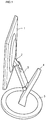
- Fig. 1 is a perspective view of a display device stand according to the present invention.
- a stand includes a display device 1 mounted thereon, a rear fixing portion 2 fixed to the rear of the display device 1, a sliding portion 3 extending approximately downward from the rear fixing portion 2, a supporting portion 4 for supporting the lower end of the sliding portion 3 and guiding the movement of the sliding portion 3 in a downward direction, and a base 5 supporting the lower end of the supporting portion 4 and supporting the display device 1 on a flat surface.
- the connecting points allow each of the members to which they are connected to pivot. Because of their ability to pivot on the hinges, the members may be collectively manipulated by a user to conveniently achieve a desired position of the display device.
- a quadric crank mechanism structure is provided inside the sliding portion 3, when the sliding portion 3 is pivoted, the tilt angle of the display device 1 is maintained. Through this adjustment, a user can conveniently adjust the height of the display device 1 while maintaining the original tilt angle of the display device 1.
- the lower end of the sliding portion 3 While the lower end of the sliding portion 3 is supported by the supporting portion 4, the lower end is capable of being slid along the extended length of the supporting portion 4. Therefore, when a user wishes to adjust the height of the display device 1, the user may move the sliding portion 3 vertically along the supporting portion 4 to conveniently adjust the height of the display device 1.
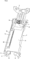
- Fig. 2 is a perspective view of a sliding portion according to the present invention
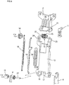
- Fig. 3 is an exploded perspective view of a sliding portion according to the present invention.
- the sliding portion 3 includes a first connecting portion connecting an upper end of the sliding portion 3 to the rear fixing portion 2, a second connecting portion connecting the lower end of the sliding portion 3 to the supporting portion 4, and a link portion connecting the first connecting portion to the second connecting portion.
- the link portion includes a main link 13 linking the first connecting portion to the second connecting portion and imparting a predetermined connecting force therebetween, and an auxiliary link consisting of auxiliary link bars 18 and 19 disposed at one side of the main link 13 and acting as a quadric crank mechanism.
- the upper ends of the auxiliary link bars 18 and 19 act as the pivoting center of the link and are connected at respectively different and eccentric dispositions to the center of rotation of a link hinge 14.
- the lower portion of the auxiliary link bars 18 and 19 are connected at respectively different and eccentric dispositions to the center of rotation of a supporting hinge 15.
- the auxiliary link bars 18 and 19, the link hinge 14 and the supporting hinge 15 may function as a quadric crank mechanism.
- the quadric crank mechanism provides a parallelogram structure, wherein when one edge is fixed and the edge opposite thereto is moved, the opposite edge moves parallelly with the one edge.
- this characteristic of a quadric crank mechanism can maintain the same tilt angle of the display device 1 when the sliding portion 3 is pivoted.
- the first connecting portion includes a hinge spring member 12 provided with a first hinge axis 21 formed at the lower end of the rear fixing portion 2 and a second hinge axis 22.
- the first hinge axis 21 and a hinge spring member 25 allow the first connecting portion to perform two types of pivoting operations.
- the first hinge axis 21 is guided by a first hinge receiving portion 23 formed on the upper portion of the main link 13, and is covered and supported by the hinge coupling portion 11. Therefore, the first hinge axis 21 can rotate while being guided by the first hinge receiving portion 23.
- the second hinge axis 22 is coupled to the link hinge 14 through a second hinge receiving portion 24.
- Two members that are capable of rotating with respect to one another are provided inside the hinge spring member 12. The two members are connected through the hinge spring 25. One of the two members is fixed to the second hinge axis 22 and rotates together with the link hinge 14. The other of the two members is fixed to the first hinge axis 21 and rotates together with the rear fixing portion 2.
- a washer or other member for providing friction is provided within the hinge spring member 12. The friction provided by the washer or other friction providing member between the two members inside the hinge spring member 12 is greater than the friction provided between the first hinge axis 21 and the first hinge receiving portion 23.
- the link hinge 14 of the quadric crank mechanism rotates about the supporting hinge 15.
- the link hinge 14 does not rotate due to the operation of the quadric crank mechanism, and performs only orbital movement about the supporting hinge 15.
- the second hinge axis 22 fixedly connected to the link hinge 14 also moves only in an orbiting fashion.
- the friction provided by the washer or other friction providing member between the two inner members in the hinge spring member 12 is greater than the friction provided between the first hinge axis 21 and the first hinge receiving portion 23. Therefore, the two members inside the hinge spring member 12 do not rotate relative to each other, and the hinge spring member 12 rotates together with the first hinge axis 21. Instead, rotation occurs between the first hinge axis 21 and the first hinge receiving portion 23, so that the main link 13 and the rear fixing portion 2 rotate differently. Thus, the display device 1 fixed to the rear fixing portion 2 rotates with respect to the main link 13.
- This rotation causes the tilt angle of the display device 1 to remain the same throughout a pivoting of the sliding portion 3 at a lower end thereof. Therefore, the user can always view the display device 1 at the same tilt angle.
- the second connecting portion is a component formed between the sliding portion 3 and the supporting portion 4, and includes a first supporting axis 27, a supporting hinge 15 inserted sequentially in the first supporting axis 27, a supporting portion 4, a lower portion of the main link 13, and a first friction portion 16.
- the first friction portion 16 is fixed with respect to the first supporting axis 27. Furthermore, at least one side thereof contacts the lower surface of the main link 13 and provides force pressing the main link 13 in an upward direction when the main link 13 rotates downward. This also applies to the second friction member 17.
- the first friction member 16 and the second friction member 17 are able to provide sufficient restoring force in any direction, when the display device 1 moves upward or downward due to the wound directions being different with respect to the first supporting axis 27.
- the first supporting axis 27 is inserted so that is cannot rotate with respect to the supporting hinge 15.
- the first supporting axis 27 that is inserted in the supporting hinge 15 may have a portion thereof formed in a non-circular shape.
- the first supporting axis 27 is fixed with respect to the first friction portion 16.
- the contacting region between the supporting portion and the first supporting axis 27 is supported by a first frictional force, and a predetermined second frictional force supports the contacting region between the lower end of the main link 13 and the first supporting axis 27.
- the first frictional force is made to be greater than the second frictional force. Therefore, under normal conditions, when an external force is applied to the display device 1 to rotate the main link 13, the first supporting axis 27 and the lower end of the main link 13 rotate against each other. In this case, the tilt angle of the display device 1 is maintained while the height of the display device 1 is adjusted.
- An elastic member 26 is connected between the second supporting link 19 and the main link 13, so that when a user pivots the main link 13, the elastic member 26 exerts a force in a predetermined direction against the main link 13.
- the auxiliary link 19 is connected at an eccentric disposition to the center of the rotating axis of the main link 13, so that the elastic member 26 expands and generates elasticity when the main link 13 is rotated.
- This elasticity is a force for returning the main link 13 and the auxiliary link 19 to their original positions.
- the deadweight of the display device 1 may be supported by means of the force.
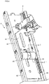
- Fig. 4 is a frontal perspective view of a supporting portion according to the present invention
- Fig. 5 is a sectional view of the supporting portion in Fig. 4 taken along line I-I'.
- the supporting portion 4 includes a guide panel 42 forming a frame thereof, a slide panel 41 along which the guide panel 42 moves in an extending direction, and a plate spring 45 for supporting the movement of the slide panel 41 with the guide panel 42 in a fixed state.
- a guide protrusion 44 is formed on a side of the slide panel 41, and an extending slot 43 is formed at the location of the guide panel 42 opposite to the guide protrusion 44.
- the supporting portion 4 in the above structure will now be described.
- the slide panel 41 pushes the plate spring 45 to unwind the plate spring 45.
- the plate spring 45 provides drag preventing the slide panel 41 from descending, so that the deadweight of the display device 1 can be conveniently raised in an upward direction.
- friction is applied to the plate spring 45 so that when the slide panel 41 attains a predetermined height, the display device 1 is stably supported.
- one end of the plate spring 45 is fixed to the guide panel 42, and the other end is wound at a predetermined curvature and put in contact with the slide panel 41.
- the guide protrusion 44 is able to move only within the extending slot 43, the vertical movement of the slide panel 41 is guided by the guide panel 42.
- the top and bottom ends of the guide panel may form a predetermined stopper.
- Figs. 6 through 8 are side views for describing operating modes of a stand according to the present invention, where Fig. 6 shows an operating mode in which the tilt angle of the display device is maintained while moving the display device vertically.
- the sliding portion pivots about the second connecting portion connecting the sliding portion 3 and the supporting portion 4.
- the quadric crank mechanism provided within the sliding portion 3 maintains the tilt angle of the display device 1 in its original position.
- This operational mode may be used in order to retain the viewing angle at which a user views the display device while moving the display device forward or backward.
- Fig. 7 shows an operating mode in which a sliding portion moves vertically along a supporting portion.
- the plate spring 45 supports the deadweight of the display device 1
- a user may adjust the height of the display device 1 by raising or lowering the same along an extending direction of the supporting portion 4.
- the display device 1 may be adjusted to a height greater than in the related art.
- Fig. 8 shows an operating mode in which the display device itself is pivoted. Referring to Fig. 8 , because the two members provided within the hinge spring member 12 are rotated, the angle at which a user views the display device may be tilted.
- the viewing angle of the display device 1 may be adjusted with more precision and accuracy, the viewing angle of the display device can be adjusted to an angle at which the picture is clearest.
- FIG. 6 through 8 Each operating mode shown in Figs. 6 through 8 may be performed separately or in combination.
- the height and tilt angle adjustments of the display device according to the present invention allow for a wide range of adjustments, so that the position of the display device can be easily adjusted, providing users with increased convenience.
- the structure of the display device is made simple, a wide assortment of operating modes are possible.
- the product can be inexpensively manufactured.
Description
- The present invention relates to a stand for a display device, and more particularly, to a stand for a display device that allows the display device to be conveniently adjusted to any one of a variety of positions desired by a user. Still more particularly, the stand for a display device has a wide height adjusting range.
- Monitors are representative examples of display devices, and are capable of being adjusted to a variety of positions to suit users' preferences. In order to conveniently move such display devices, stands with quadric crank mechanism to conveniently adjust angles of display devices are provided in the related art. A stand for a display device employing the quadric crank mechanism structure allows the tilt angle of the display device to remain unchanged when the position of the display device is altered, thereby increasing the level of user convenience.
- However, in a display device stand employing the quadric crank mechanism according to the related art, the process of adjusting the position of the display device can only be performed by changing the center of gravity of the stand by pivoting the stand. Therefore, adjusting the position of the display device is limited to pivoting the display device about the base of the stand.
- Also, due to a limit in the amount by which the height of the display can be adjusted, functional versatility of the stand is reduced.
-
JP 2004 333744 A WO 2004/079699 A disclose display apparatus allowing the sliding of the display upward and downward, as well as some means allowing tilting of the display.US 2006/0000956 A1 discloses a display apparatus according to the preamble of claim 1. - Accordingly, the present invention is directed to a stand for a display device that substantially obviates one or more problems due to limitations and disadvantages of the related art.
- An object of the present invention is to provide a stand for a display device capable of adjusting the height of the display device in various ways, and facilitating the adjustment of the display device's position to increase user convenience.
- Another object of the present invention is to provide a stand for a display device capable of raising the display device higher than in the related art, further increasing user convenience.
- A further object of the present invention is to provide an inexpensive stand for a display device capable of changing and adjusting the position of the display device in various ways.
- Additional advantages, objects, and features of the invention will be set forth in part in the description which follows and in part will become apparent to those having ordinary skill in the art upon examination of the following or may be learned from practice of the invention. The objectives and other advantages of the invention may be realized and attained by the structure particularly pointed out in the written description and claims hereof as well as the appended drawings.
- To achieve these objects and other advantages and in accordance with the purpose of the invention, as embodied and broadly described herein, a stand according to claim 1 is proposed.
- As described, the stand of the display device according to the present invention is capable of adjusting the position of the display device in a variety of ways to suit a user's requirements, and prevents the tilt angle of the display device from changing while a user adjusts the position of the display device. Thus, the level of user convenience increases. In particular, the range in which the height of the display device can be adjusted is increased.
- It is to be understood that both the foregoing general description and the following detailed description of the present invention are exemplary and explanatory and are intended to provide further explanation of the invention as claimed.
- The accompanying drawings, which are included to provide a further understanding of the invention and are incorporated in and constitute a part of this application, illustrate embodiment(s) of the invention and together with the description serve to explain the principle of the invention. In the drawings:
-
Fig. 1 is a perspective view of a display device stand according to the present invention; -
Fig. 2 is a perspective view of a sliding portion according to the present invention; -
Fig. 3 is an exploded perspective view of a sliding portion according to the present invention; -
Fig. 4 is a frontal perspective view of a supporting portion according to the present invention; -
Fig. 5 is a sectional view of the supporting portion inFig. 4 taken along line I-I'; and -
Figs. 6 through 8 are side views for describing operating modes of a stand according to the present invention, whereFig. 6 shows an operating mode in which the tilt angle of the display device is maintained while moving the display device vertically,Fig. 7 shows an operating mode in which a sliding portion moves vertically along a supporting portion, andFig. 8 shows an operating mode in which the display device itself is pivoted. - Reference will now be made in detail to the preferred embodiments of the present invention, examples of which are illustrated in the accompanying drawings. Wherever possible, the same reference numbers will be used throughout the drawings to refer to the same or like parts.
-
Fig. 1 is a perspective view of a display device stand according to the present invention. - Referring to
Fig. 1 , a stand according to the present invention includes a display device 1 mounted thereon, arear fixing portion 2 fixed to the rear of the display device 1, a slidingportion 3 extending approximately downward from therear fixing portion 2, a supportingportion 4 for supporting the lower end of the slidingportion 3 and guiding the movement of the slidingportion 3 in a downward direction, and abase 5 supporting the lower end of the supportingportion 4 and supporting the display device 1 on a flat surface. - Because the point connecting the
rear fixing portion 2 to the slidingportion 3 and the point connecting the slidingportion 3 to the supportingportion 4 are hinge connections, the connecting points allow each of the members to which they are connected to pivot. Because of their ability to pivot on the hinges, the members may be collectively manipulated by a user to conveniently achieve a desired position of the display device. - Also, because a quadric crank mechanism structure is provided inside the sliding
portion 3, when the slidingportion 3 is pivoted, the tilt angle of the display device 1 is maintained. Through this adjustment, a user can conveniently adjust the height of the display device 1 while maintaining the original tilt angle of the display device 1. - While the lower end of the sliding
portion 3 is supported by the supportingportion 4, the lower end is capable of being slid along the extended length of the supportingportion 4. Therefore, when a user wishes to adjust the height of the display device 1, the user may move the slidingportion 3 vertically along the supportingportion 4 to conveniently adjust the height of the display device 1. - Each position adjusting operation of the above display device will be described in detail at a later point with reference to
Figs. 6 through 8 . - Below a detailed description of the structure of the display device stand according to the present invention will be provided.
-
Fig. 2 is a perspective view of a sliding portion according to the present invention, andFig. 3 is an exploded perspective view of a sliding portion according to the present invention. - Referring to
Figs. 2 and3 , the slidingportion 3 includes a first connecting portion connecting an upper end of the slidingportion 3 to therear fixing portion 2, a second connecting portion connecting the lower end of thesliding portion 3 to the supportingportion 4, and a link portion connecting the first connecting portion to the second connecting portion. - In further detail, the link portion includes a
main link 13 linking the first connecting portion to the second connecting portion and imparting a predetermined connecting force therebetween, and an auxiliary link consisting ofauxiliary link bars main link 13 and acting as a quadric crank mechanism. The upper ends of theauxiliary link bars link hinge 14. The lower portion of theauxiliary link bars hinge 15. Thus, in this structure, theauxiliary link bars link hinge 14 and the supportinghinge 15 may function as a quadric crank mechanism. - The quadric crank mechanism provides a parallelogram structure, wherein when one edge is fixed and the edge opposite thereto is moved, the opposite edge moves parallelly with the one edge. Thus, this characteristic of a quadric crank mechanism can maintain the same tilt angle of the display device 1 when the sliding
portion 3 is pivoted. - Specifically, the first connecting portion includes a
hinge spring member 12 provided with afirst hinge axis 21 formed at the lower end of therear fixing portion 2 and asecond hinge axis 22. Thefirst hinge axis 21 and ahinge spring member 25 allow the first connecting portion to perform two types of pivoting operations. - A detailed description of the structure of the first connecting portion will be given below. First, the
first hinge axis 21 is guided by a firsthinge receiving portion 23 formed on the upper portion of themain link 13, and is covered and supported by thehinge coupling portion 11. Therefore, thefirst hinge axis 21 can rotate while being guided by the firsthinge receiving portion 23. - Also, with the
hinge spring 25 placed on thefirst hinge axis 21, thesecond hinge axis 22 is coupled to thelink hinge 14 through a secondhinge receiving portion 24. Two members that are capable of rotating with respect to one another are provided inside thehinge spring member 12. The two members are connected through thehinge spring 25. One of the two members is fixed to thesecond hinge axis 22 and rotates together with thelink hinge 14. The other of the two members is fixed to thefirst hinge axis 21 and rotates together with therear fixing portion 2. Of course, a washer or other member for providing friction is provided within thehinge spring member 12. The friction provided by the washer or other friction providing member between the two members inside thehinge spring member 12 is greater than the friction provided between thefirst hinge axis 21 and the firsthinge receiving portion 23. - The operation of the first connecting portion will now be described.
- First, when a user moves the display device 1 in order to adjust its height, the
link hinge 14 of the quadric crank mechanism rotates about the supportinghinge 15. However, thelink hinge 14 does not rotate due to the operation of the quadric crank mechanism, and performs only orbital movement about the supportinghinge 15. Thus, thesecond hinge axis 22 fixedly connected to thelink hinge 14 also moves only in an orbiting fashion. - In this state, the friction provided by the washer or other friction providing member between the two inner members in the
hinge spring member 12 is greater than the friction provided between thefirst hinge axis 21 and the firsthinge receiving portion 23. Therefore, the two members inside thehinge spring member 12 do not rotate relative to each other, and thehinge spring member 12 rotates together with thefirst hinge axis 21. Instead, rotation occurs between thefirst hinge axis 21 and the firsthinge receiving portion 23, so that themain link 13 and therear fixing portion 2 rotate differently. Thus, the display device 1 fixed to therear fixing portion 2 rotates with respect to themain link 13. - This rotation causes the tilt angle of the display device 1 to remain the same throughout a pivoting of the sliding
portion 3 at a lower end thereof. Therefore, the user can always view the display device 1 at the same tilt angle. - However, when a user wishes to adjust only the tilt angle of the display device 1, a substantial amount of force must be applied to the display device 1 to rotate the two members inside the
hinge spring member 12 and adjust the tilt angle of the display device 1 itself. - The structure and operation of the second connecting portion will now be described.
- The second connecting portion is a component formed between the sliding
portion 3 and the supportingportion 4, and includes a first supportingaxis 27, a supportinghinge 15 inserted sequentially in the first supportingaxis 27, a supportingportion 4, a lower portion of themain link 13, and afirst friction portion 16. Also, thefirst friction portion 16 is fixed with respect to the first supportingaxis 27. Furthermore, at least one side thereof contacts the lower surface of themain link 13 and provides force pressing themain link 13 in an upward direction when themain link 13 rotates downward. This also applies to thesecond friction member 17. Here, thefirst friction member 16 and thesecond friction member 17 are able to provide sufficient restoring force in any direction, when the display device 1 moves upward or downward due to the wound directions being different with respect to the first supportingaxis 27. - Also, the first supporting
axis 27 is inserted so that is cannot rotate with respect to the supportinghinge 15. For this, the first supportingaxis 27 that is inserted in the supportinghinge 15 may have a portion thereof formed in a non-circular shape. Also, the first supportingaxis 27 is fixed with respect to thefirst friction portion 16. - The contacting region between the supporting portion and the first supporting
axis 27 is supported by a first frictional force, and a predetermined second frictional force supports the contacting region between the lower end of themain link 13 and the first supportingaxis 27. Here, the first frictional force is made to be greater than the second frictional force. Therefore, under normal conditions, when an external force is applied to the display device 1 to rotate themain link 13, the first supportingaxis 27 and the lower end of themain link 13 rotate against each other. In this case, the tilt angle of the display device 1 is maintained while the height of the display device 1 is adjusted. Conversely, when a user wishes to change only the height of themain link 13, that is, only the tilt angle of the main link without maintaining the tilt angle of the display device 1, a substantial level of force is exerted to rotate the supportingportion 4 against the first supportingaxis 27 to change the degree of twist between the supportingportion 4 and the supportinghinge 15. - An
elastic member 26 is connected between the second supportinglink 19 and themain link 13, so that when a user pivots themain link 13, theelastic member 26 exerts a force in a predetermined direction against themain link 13. Specifically, theauxiliary link 19 is connected at an eccentric disposition to the center of the rotating axis of themain link 13, so that theelastic member 26 expands and generates elasticity when themain link 13 is rotated. This elasticity is a force for returning themain link 13 and theauxiliary link 19 to their original positions. For example, when the restoring force of theelastic member 26 is applied in a direction in which themain link 13 rises, the deadweight of the display device 1 may be supported by means of the force. - Below, the relationship between the supporting portion and the sliding portion will be described in detail.
-
Fig. 4 is a frontal perspective view of a supporting portion according to the present invention, andFig. 5 is a sectional view of the supporting portion inFig. 4 taken along line I-I'. - Referring to
Figs. 4 and5 , the supportingportion 4 includes aguide panel 42 forming a frame thereof, aslide panel 41 along which theguide panel 42 moves in an extending direction, and aplate spring 45 for supporting the movement of theslide panel 41 with theguide panel 42 in a fixed state. - Also, a
guide protrusion 44 is formed on a side of theslide panel 41, and an extendingslot 43 is formed at the location of theguide panel 42 opposite to theguide protrusion 44. - The operation of the supporting
portion 4 in the above structure will now be described. First, when a user exerts force on the slidingportion 3 in a downward direction, theslide panel 41 pushes theplate spring 45 to unwind theplate spring 45. Here, theplate spring 45 provides drag preventing theslide panel 41 from descending, so that the deadweight of the display device 1 can be conveniently raised in an upward direction. Also, friction is applied to theplate spring 45 so that when theslide panel 41 attains a predetermined height, the display device 1 is stably supported. - In order for the
plate spring 45 to perform the above function, one end of theplate spring 45 is fixed to theguide panel 42, and the other end is wound at a predetermined curvature and put in contact with theslide panel 41. - Because the
guide protrusion 44 is able to move only within the extendingslot 43, the vertical movement of theslide panel 41 is guided by theguide panel 42. Of course, in order to ensure that theslide panel 41 does not disengage from the top end or bottom end of theguide panel 42, the top and bottom ends of the guide panel may form a predetermined stopper. - The structure of the above display device stand according to the present invention has been sufficiently explained. Below, the operation of the stand according to the present invention will be described.
-
Figs. 6 through 8 are side views for describing operating modes of a stand according to the present invention, whereFig. 6 shows an operating mode in which the tilt angle of the display device is maintained while moving the display device vertically. - Referring to
Fig. 6 , when a user applies a relatively weak force to the display device 1, the sliding portion pivots about the second connecting portion connecting the slidingportion 3 and the supportingportion 4. Here also, the quadric crank mechanism provided within the slidingportion 3 maintains the tilt angle of the display device 1 in its original position. - This operational mode may be used in order to retain the viewing angle at which a user views the display device while moving the display device forward or backward.
-
Fig. 7 shows an operating mode in which a sliding portion moves vertically along a supporting portion. Referring toFig. 7 , while theplate spring 45 supports the deadweight of the display device 1, a user may adjust the height of the display device 1 by raising or lowering the same along an extending direction of the supportingportion 4. - In the case of this operating mode, because the display device 1 and the sliding
portion 3 are elevated together, the display device 1 may be adjusted to a height greater than in the related art. -
Fig. 8 shows an operating mode in which the display device itself is pivoted. Referring toFig. 8 , because the two members provided within thehinge spring member 12 are rotated, the angle at which a user views the display device may be tilted. - In the case of this operating mode, because the viewing angle of the display device 1 may be adjusted with more precision and accuracy, the viewing angle of the display device can be adjusted to an angle at which the picture is clearest.
- Each operating mode shown in
Figs. 6 through 8 may be performed separately or in combination. - As described, the height and tilt angle adjustments of the display device according to the present invention allow for a wide range of adjustments, so that the position of the display device can be easily adjusted, providing users with increased convenience.
- Also, because the structure of the display device is made simple, a wide assortment of operating modes are possible. Thus, the product can be inexpensively manufactured.
- It will be apparent to those skilled in the art that various modifications and variations can be made in the present invention. Thus, it is intended that the present invention covers the modifications and variations of this invention provided they come within the scope of the appended claims and their equivalents.
Claims (11)
- A system comprising a display device and stand for the display device, the stand comprising:a sliding portion (3) extending toward a rear surface of the display device (1) and supported at one end thereof on the display device (1);a supporting portion (4) for slidably supporting the sliding portion (3); anda base (5) for supporting the supporting portion, the base (5) extending the supporting portion (4) upward,wherein the supporting portion (4) comprises:a slide panel (41) to which a lower end of the sliding portion (3) is coupled;a guide panel (42) along which the slide panel (41) is guided and moves in an extending direction of the supporting portion (4); anda spring (45) capable for expanding and contracting while contacting the slide panel (41), and having at least one end thereof fixed to the guide panel (42), and providing drag preventing the slide panel (41) from descending, so that the deadweight of the display device (1) can be conveniently raised in an upward direction , and the sliding portion (3) and the supporting portion (4) are formed to extend in mutually different directions,characterized in that the sliding portion (3) comprises a quadric crank mechanism for maintaining a tilt angle of the display device (1) when a force below a predetermined level is applied to the display device (1), said quadric crank mechanism comprising:a link hinge (14) providing a hinge connection between the sliding portion (3) and the display device (1);a supporting hinge (15) providing a hinge connection between the sliding portion (3) and the supporting portion (4);a pair of auxiliary links (18,19) eccentrically connecting the link hinge (14) to the supporting hinge (15); anda main link (13) connecting the link hinge (14) and the supporting hinge (15),wherein a first supporting axis (27) is inserted so that is cannot rotate with respect to the supporting hinge (15),wherein a first friction portion (16) and a second friction portion (17) are fixed with respect to the first supporting axis (27), and at least one side thereof contacts the lower surface of the main link (13), and provides force pressing the main link (13) in an upward direction when the main link (13) rotates downward,wherein the first friction portion (16) and the second friction portion (17) are able to provide sufficient restoring force in any direction, when the display device (1) moves upward or downward due to the wound directions being different with respect to the first supporting axis (27).
- The system according to claim 1, wherein the sliding portion (3) and a connecting portion of the display device (1) are respectively capable of rotating.
- The system according to claim 1, wherein a lower end of the sliding portion (3) is supported by a frictional force against the supporting portion (4).
- The system according to claim 1, wherein the supporting portion (4) supports a lower end of the sliding portion (3).
- The system according to claim 1, wherein the supporting portion (4) further comprises:an extending slot (43) formed in an extending direction of the guide panel (42); anda guide protrusion (44) protruding from the slide panel(41), for being guided by the extending slot (43).
- The system according to claim 1, wherein at least a portion of the spring (45) contacting the slide panel (41) is wound.
- The system according to claim 1, wherein when an external force is applied to the display device (1), the display device (1) is orbited while maintaining a tilt angle thereof, prior to a changing of the tilt angle of the display device (1).
- The system according to claim 1, wherein the supporting portion (4) extends upward while reclined rearward with respect to the base (5).
- The system according to claim 1, wherein the sliding portion (3) extends in a forward direction from the supporting portion (4).
- The system according to claim 1, wherein a surface guiding the sliding portion (3) on the supporting portion (4) is a front surface of the supporting portion (4).
- The system according to claim 1, wherein the sliding portion (3) slides along an extending direction of the supporting portion (4).
Applications Claiming Priority (1)
| Application Number | Priority Date | Filing Date | Title |
|---|---|---|---|
| KR1020060015878A KR101239009B1 (en) | 2006-02-17 | 2006-02-17 | Stand of a display device |
Publications (3)
| Publication Number | Publication Date |
|---|---|
| EP1821027A2 EP1821027A2 (en) | 2007-08-22 |
| EP1821027A3 EP1821027A3 (en) | 2008-10-08 |
| EP1821027B1 true EP1821027B1 (en) | 2018-11-21 |
Family
ID=38050140
Family Applications (1)
| Application Number | Title | Priority Date | Filing Date |
|---|---|---|---|
| EP07290170.5A Active EP1821027B1 (en) | 2006-02-17 | 2007-02-12 | Stand for display device |
Country Status (4)
| Country | Link |
|---|---|
| US (1) | US7669812B2 (en) |
| EP (1) | EP1821027B1 (en) |
| KR (1) | KR101239009B1 (en) |
| CN (1) | CN101026018A (en) |
Families Citing this family (16)
| Publication number | Priority date | Publication date | Assignee | Title |
|---|---|---|---|---|
| KR100793754B1 (en) * | 2006-07-07 | 2008-01-10 | 엘지전자 주식회사 | Display device |
| ITPI20080042A1 (en) * | 2008-05-15 | 2009-11-16 | Domenico Morello | SUPPORT FOR DISPLAY SCREEN TELEVISION |
| JP4923121B2 (en) * | 2010-02-25 | 2012-04-25 | 東芝テック株式会社 | Display device and display device system |
| US9188275B2 (en) | 2010-07-30 | 2015-11-17 | Ergotron, Inc. | Edge mount positioning apparatus, system, and method |
| AU2011282863B2 (en) | 2010-07-30 | 2015-07-23 | Ergotron, Inc. | Display positioning apparatus and method |
| CN103477143B (en) * | 2011-02-11 | 2016-09-28 | 爱格升公司 | Bifocal display location equipment and method |
| US8998161B2 (en) * | 2013-07-25 | 2015-04-07 | Matthew K. E. Larson | Apparatus for holding portable devices |
| US9618976B2 (en) * | 2013-12-10 | 2017-04-11 | Lenovo (Singapore) Pte. Ltd. | Hinged computer stand that slides up and down on a video display |
| US10813451B2 (en) | 2014-04-08 | 2020-10-27 | Hypnap LLC | Mobile device stand |
| USD776668S1 (en) * | 2014-11-18 | 2017-01-17 | Lenovo (Singapore) Pte. Ltd. | Display stand |
| DE102015220813A1 (en) * | 2015-10-23 | 2017-04-27 | Andreas Seibold | Device for panning a virtual reality display and method for displaying a virtual reality scene |
| CN108153380B (en) * | 2017-12-22 | 2021-09-14 | 联想(北京)有限公司 | Support member for display and electronic apparatus |
| CN109521839B (en) * | 2018-11-10 | 2020-05-12 | 万翼方教育科技(江苏)有限公司 | Elevation angle adjustable computer display screen |
| US11737570B2 (en) | 2021-08-13 | 2023-08-29 | Hypnap LLC | Apparatus for supporting a user in a forward-leaning position with base proximity adjustability |
| US11930931B2 (en) | 2021-08-13 | 2024-03-19 | Hypnap LLC | Apparatus for supporting a user in a forward-leaning position with faceplate pivotability |
| CN114935082B (en) * | 2022-05-10 | 2023-11-03 | 田霞 | High-end peripheral hardware installation display device for computer |
Family Cites Families (11)
| Publication number | Priority date | Publication date | Assignee | Title |
|---|---|---|---|---|
| KR100512718B1 (en) * | 2002-07-16 | 2005-09-07 | 삼성전자주식회사 | Monitor |
| JP2004271595A (en) * | 2003-03-05 | 2004-09-30 | Sony Corp | Display device |
| TW591286B (en) * | 2003-03-27 | 2004-06-11 | Benq Corp | Liquid crystal display and support thereof |
| JP3757217B2 (en) * | 2003-05-06 | 2006-03-22 | 株式会社ナナオ | LCD display stand |
| KR100662367B1 (en) * | 2004-05-06 | 2007-01-02 | 엘지전자 주식회사 | Stand Assembly for Monitor |
| WO2005124742A2 (en) * | 2004-06-14 | 2005-12-29 | Sava Cvek | Trolley and rail systems for extension and retraction arrangements |
| US7770856B2 (en) * | 2004-08-13 | 2010-08-10 | Hewlett-Packard Development Company, L.P. | Thin computer monitor support apparatus |
| KR100658836B1 (en) * | 2005-08-16 | 2006-12-15 | 엘지전자 주식회사 | Stand device |
| KR101237560B1 (en) * | 2006-02-17 | 2013-02-26 | 엘지전자 주식회사 | Stand of a display device |
| KR100710313B1 (en) * | 2006-05-26 | 2007-04-23 | 엘지전자 주식회사 | Display device |
| KR100710314B1 (en) * | 2006-06-01 | 2007-04-23 | 엘지전자 주식회사 | Monitor stand |
-
2006
- 2006-02-17 KR KR1020060015878A patent/KR101239009B1/en active IP Right Grant
-
2007
- 2007-02-12 EP EP07290170.5A patent/EP1821027B1/en active Active
- 2007-02-15 US US11/706,197 patent/US7669812B2/en not_active Expired - Fee Related
- 2007-02-16 CN CNA200710005394XA patent/CN101026018A/en active Pending
Non-Patent Citations (1)
| Title |
|---|
| None * |
Also Published As
| Publication number | Publication date |
|---|---|
| EP1821027A3 (en) | 2008-10-08 |
| KR20070082795A (en) | 2007-08-22 |
| EP1821027A2 (en) | 2007-08-22 |
| US7669812B2 (en) | 2010-03-02 |
| US20070228253A1 (en) | 2007-10-04 |
| CN101026018A (en) | 2007-08-29 |
| KR101239009B1 (en) | 2013-03-04 |
Similar Documents
| Publication | Publication Date | Title |
|---|---|---|
| EP1821027B1 (en) | Stand for display device | |
| EP1821024B1 (en) | Stand for display device | |
| KR100684998B1 (en) | Monitor | |
| EP1860366B1 (en) | Monitor stand | |
| EP1821029A2 (en) | Stand and display apparatus having the same | |
| US7717384B2 (en) | Stand of display device | |
| US7578490B2 (en) | Stand of display device | |
| EP1862723B1 (en) | Monitor stand | |
| EP1862724B1 (en) | Monitor stand | |
| CN101501386B (en) | Display device | |
| EP1840445A2 (en) | Display apparatus | |
| US20090101777A1 (en) | Wall mount supporting apparatus of flat panel display device | |
| KR100609852B1 (en) | Display apparatus | |
| KR20060016664A (en) | Monitor | |
| KR101529689B1 (en) | Supporting apparatus for Display device | |
| EP2146131B1 (en) | Display device | |
| KR100465798B1 (en) | Monitor | |
| KR20090072775A (en) | Mounting apparatus for flat display device | |
| KR20060018584A (en) | Hinge assembly for display device | |
| KR200381244Y1 (en) | Hinge apparatus of LCD monitor |
Legal Events
| Date | Code | Title | Description |
|---|---|---|---|
| PUAI | Public reference made under article 153(3) epc to a published international application that has entered the european phase |
Free format text: ORIGINAL CODE: 0009012 |
|
| 17P | Request for examination filed |
Effective date: 20070223 |
|
| AK | Designated contracting states |
Kind code of ref document: A2 Designated state(s): AT BE BG CH CY CZ DE DK EE ES FI FR GB GR HU IE IS IT LI LT LU LV MC NL PL PT RO SE SI SK TR |
|
| AX | Request for extension of the european patent |
Extension state: AL BA HR MK YU |
|
| PUAL | Search report despatched |
Free format text: ORIGINAL CODE: 0009013 |
|
| AK | Designated contracting states |
Kind code of ref document: A3 Designated state(s): AT BE BG CH CY CZ DE DK EE ES FI FR GB GR HU IE IS IT LI LT LU LV MC NL PL PT RO SE SI SK TR |
|
| AX | Request for extension of the european patent |
Extension state: AL BA HR MK RS |
|
| 17Q | First examination report despatched |
Effective date: 20090320 |
|
| AKX | Designation fees paid |
Designated state(s): DE FR GB |
|
| RAP1 | Party data changed (applicant data changed or rights of an application transferred) |
Owner name: LG ELECTRONICS INC. |
|
| REG | Reference to a national code |
Ref country code: DE Ref legal event code: R079 Ref document number: 602007056873 Country of ref document: DE Free format text: PREVIOUS MAIN CLASS: F16M0011040000 Ipc: F16M0011100000 |
|
| GRAP | Despatch of communication of intention to grant a patent |
Free format text: ORIGINAL CODE: EPIDOSNIGR1 |
|
| RIC1 | Information provided on ipc code assigned before grant |
Ipc: F16M 11/24 20060101ALI20180419BHEP Ipc: F16M 11/10 20060101AFI20180419BHEP |
|
| INTG | Intention to grant announced |
Effective date: 20180517 |
|
| GRAS | Grant fee paid |
Free format text: ORIGINAL CODE: EPIDOSNIGR3 |
|
| GRAJ | Information related to disapproval of communication of intention to grant by the applicant or resumption of examination proceedings by the epo deleted |
Free format text: ORIGINAL CODE: EPIDOSDIGR1 |
|
| GRAL | Information related to payment of fee for publishing/printing deleted |
Free format text: ORIGINAL CODE: EPIDOSDIGR3 |
|
| GRAR | Information related to intention to grant a patent recorded |
Free format text: ORIGINAL CODE: EPIDOSNIGR71 |
|
| GRAA | (expected) grant |
Free format text: ORIGINAL CODE: 0009210 |
|
| INTC | Intention to grant announced (deleted) | ||
| AK | Designated contracting states |
Kind code of ref document: B1 Designated state(s): DE FR GB |
|
| INTG | Intention to grant announced |
Effective date: 20181012 |
|
| REG | Reference to a national code |
Ref country code: DE Ref legal event code: R096 Ref document number: 602007056873 Country of ref document: DE |
|
| REG | Reference to a national code |
Ref country code: DE Ref legal event code: R097 Ref document number: 602007056873 Country of ref document: DE |
|
| PLBE | No opposition filed within time limit |
Free format text: ORIGINAL CODE: 0009261 |
|
| STAA | Information on the status of an ep patent application or granted ep patent |
Free format text: STATUS: NO OPPOSITION FILED WITHIN TIME LIMIT |
|
| GBPC | Gb: european patent ceased through non-payment of renewal fee |
Effective date: 20190221 |
|
| 26N | No opposition filed |
Effective date: 20190822 |
|
| PG25 | Lapsed in a contracting state [announced via postgrant information from national office to epo] |
Ref country code: GB Free format text: LAPSE BECAUSE OF NON-PAYMENT OF DUE FEES Effective date: 20190221 |
|
| PG25 | Lapsed in a contracting state [announced via postgrant information from national office to epo] |
Ref country code: FR Free format text: LAPSE BECAUSE OF NON-PAYMENT OF DUE FEES Effective date: 20190228 |
|
| PGFP | Annual fee paid to national office [announced via postgrant information from national office to epo] |
Ref country code: DE Payment date: 20230105 Year of fee payment: 17 |