EP1820731B1 - Method for sterilising bottles or similar containers and device for performing this method - Google Patents
Method for sterilising bottles or similar containers and device for performing this method Download PDFInfo
- Publication number
- EP1820731B1 EP1820731B1 EP07003481A EP07003481A EP1820731B1 EP 1820731 B1 EP1820731 B1 EP 1820731B1 EP 07003481 A EP07003481 A EP 07003481A EP 07003481 A EP07003481 A EP 07003481A EP 1820731 B1 EP1820731 B1 EP 1820731B1
- Authority
- EP
- European Patent Office
- Prior art keywords
- nozzle
- treatment
- container
- openings
- opening
- Prior art date
- Legal status (The legal status is an assumption and is not a legal conclusion. Google has not performed a legal analysis and makes no representation as to the accuracy of the status listed.)
- Expired - Fee Related
Links
Images

Classifications
-
- B—PERFORMING OPERATIONS; TRANSPORTING
- B65—CONVEYING; PACKING; STORING; HANDLING THIN OR FILAMENTARY MATERIAL
- B65B—MACHINES, APPARATUS OR DEVICES FOR, OR METHODS OF, PACKAGING ARTICLES OR MATERIALS; UNPACKING
- B65B55/00—Preserving, protecting or purifying packages or package contents in association with packaging
- B65B55/02—Sterilising, e.g. of complete packages
- B65B55/04—Sterilising wrappers or receptacles prior to, or during, packaging
- B65B55/10—Sterilising wrappers or receptacles prior to, or during, packaging by liquids or gases
-
- A—HUMAN NECESSITIES
- A61—MEDICAL OR VETERINARY SCIENCE; HYGIENE
- A61L—METHODS OR APPARATUS FOR STERILISING MATERIALS OR OBJECTS IN GENERAL; DISINFECTION, STERILISATION OR DEODORISATION OF AIR; CHEMICAL ASPECTS OF BANDAGES, DRESSINGS, ABSORBENT PADS OR SURGICAL ARTICLES; MATERIALS FOR BANDAGES, DRESSINGS, ABSORBENT PADS OR SURGICAL ARTICLES
- A61L2/00—Methods or apparatus for disinfecting or sterilising materials or objects other than foodstuffs or contact lenses; Accessories therefor
- A61L2/16—Methods or apparatus for disinfecting or sterilising materials or objects other than foodstuffs or contact lenses; Accessories therefor using chemical substances
- A61L2/22—Phase substances, e.g. smokes, aerosols or sprayed or atomised substances
-
- B—PERFORMING OPERATIONS; TRANSPORTING
- B08—CLEANING
- B08B—CLEANING IN GENERAL; PREVENTION OF FOULING IN GENERAL
- B08B9/00—Cleaning hollow articles by methods or apparatus specially adapted thereto
- B08B9/08—Cleaning containers, e.g. tanks
- B08B9/20—Cleaning containers, e.g. tanks by using apparatus into or on to which containers, e.g. bottles, jars, cans are brought
- B08B9/28—Cleaning containers, e.g. tanks by using apparatus into or on to which containers, e.g. bottles, jars, cans are brought the apparatus cleaning by splash, spray, or jet application, with or without soaking
- B08B9/34—Arrangements of conduits or nozzles
Definitions
- the invention relates to a method according to the preamble patent claim 1 and to an apparatus for performing the method according to the preamble of claim 7.
- the sterilization of bottles or similar containers by applying hydrogen peroxide (H 2 O 2 ) on the inner surfaces of the container to be sterilized for example using a treatment medium in the form of a sterile air and hydrogen peroxide aerosol and then pressurizing the container inner surfaces with hot sterile air Heating the respective container and for activating the sterilization medium and for removing this medium and any amounts of residual water at the end of the sterilization phase or sterilization process is known.
- H 2 O 2 hydrogen peroxide
- the introduction of the treatment media takes place here via a treatment nozzle, which has a single directed to the bottom of the respective container nozzle opening, so that the respective treatment medium u. a. after impinging on the container bottom flows on the container inner surface upwards and thereby distributed evenly on the inner surfaces of the container.
- the effectiveness of the sterilization process depends on an optimized flow of the respective treatment medium, d. H. the flow of the treatment medium must be such that all areas of the inner surface of the container are detected by the treatment medium or acted upon by it.
- bottles or similar containers have an inner contour deviating from the usual, continuous shape, in particular in such a way that expansions and / or less accessible or flow-less adjoining spaces are formed by the inner contour in the interior of the container, then this is the case with the previous methods used means effective sterilization not possible.
- the object of the invention is to provide a method which makes it possible to sterilize bottles or similar container with a deviating from the usual form and extensions and / or adjoining rooms, etc. forming inner contour in an optimal manner.
- a method according to the patent claim 1 is formed.
- a device is the subject of claim 7.
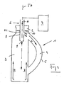
- FIG. 1 1 is a bottle or a bottle-like container with a special shape, in such a way that the interior or the volume of the bottle 2 not only from the axially adjacent to the bottle mouth 2 bottle space 3, but also from a partial or adjacent room is formed, namely, from the interior 4 of a molded onto the bottle 1 hollow handle. 5
- the partial or secondary space 4 with the treatment media (first with aerosol of sterile air and hydrogen peroxide and then with hot sterile air) is used to introduce the sterilization or Treatment media used a treatment nozzle 6, part of a in the FIG. 1 schematically indicated by the block 7 treatment or sterilization device and is introduced with its tubular nozzle body 8 through the bottle mouth 2 in the bottle 1, for example, such that the axis of the nozzle body 8 is coaxially aligned with the bottle axis FA.
- the treatment and sterilization device 7 then has, for example - apart from the special design of the treatment nozzle 6 - the known in the art construction of such a device.
- the treatment media are fed to the nozzle body 8 or the nozzle channel 8.1 formed in this body in accordance with the arrow A.
- the nozzle body 8 forms at least one nozzle opening 9 for the exit of the treatment media, in particular for the treatment of the bottle space 3 or the inner surfaces of the bottle 1 delimiting this space.
- the nozzle body 8 on its peripheral surface further, also communicating with the nozzle channel 8.1 associated nozzle openings 10, from which a subset of the nozzle channel 8.1 supplied treatment media in a direction radially or approximately radially to the axis of the nozzle body 8 exits and thereby in the of the Handle 5 formed part space 4 passes, so that this is reliably sterilized.
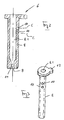
- the nozzle channel 8.1 has a constriction in the flow direction following the nozzle openings 10, as shown in FIG. 2 indicated at 11.
- the bottle 1 and the nozzle 6 are aligned relative to each other so that the nozzle openings 10 and their axes are directed to that area of the inner surface of the bottle 1, at which the compartment 4 with its upper, the bottle mouth 2 closer lying end in the bottle space 3 opens.
- the bottles 1 are provided in a predetermined orientation via an unillustrated transport system for the sterilization process.
- the nozzle 6 is designed, for example, by a special shaping of its nozzle body 8 so that it can be fastened only in the orientation necessary for the treatment of the bottles 1 on a nozzle carrier of the device 7 used for the sterilization process.
- the nozzle body 8 has an alignment aid in the form of a radially extending tab 12 at its upper end.
- the nozzle opening 9 is oriented during the sterilization process with its axis on the bottom of the bottle 1 and the bottle interior, so that the emerging from this nozzle opening treatment medium impinges on the ground and then at least partially optimally distributed to the inner surfaces of the bottle space 3 upwards as indicated by the arrows B in the FIG. 1 is shown.
- the treatment medium emerging from the additional nozzle opening 10 enters the subspace 4 as shown in FIG FIG. 1 indicated by the arrows C, so that overall results in an optimal flow, which ensures a uniform application of all areas of the bottle inner surface with the respective treatment medium.
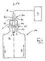
- FIG. 4 shows in a representation similar FIG. 1 a bottle 1a, which has in the region of its adjoining the bottle mouth 13 bottleneck 14 in the interior, inter alia, a side room 15 forming extension.
- the nozzle 6a corresponding to the nozzle 6 has a plurality of additional nozzle openings 10a on the circumferential or circumferential surface of its tubular nozzle body 8a.
- each group has a plurality of nozzle openings 10a, which then, for example, at equal angular intervals about the axis of the nozzle body 8a are provided distributed.
- the nozzle openings 10a of the individual groups are oriented, for example, with their axis in a different axial direction, as shown in the FIG.
- nozzle openings 10a are formed, for example, with a round or oval cross section or slot-shaped.
- the nozzle channel 8a.1 formed in the nozzle body 8a is again narrowed in the flow direction toward the nozzle openings 10a or the nozzle opening 9 corresponding nozzle opening 9a on lower end of the nozzle body 8a has a relation to the cross section of the nozzle channel 8a.1 reduced cross-section, as shown in the FIG. 5 is shown.
- All embodiments of the invention have in common that during the sterilization process via additional nozzle openings, the respective treatment medium is deliberately introduced into formed by the container shape extensions and / or side rooms of the container or bottle interior, ie also the local container inner surfaces are subjected to the respective treatment medium, the treatment the container or
- So bottles with treatment nozzles takes place, which are adapted in terms of arrangement and number of nozzle openings to the inner contour of the container or bottles and thus optimal loading of all areas of the inner surface of a container or bottle with the respective treatment medium or an optimal flow of the treatment medium during of the sterilization process.
- nozzle openings are formed by outflow openings.
- special nozzle elements which then each form one or possibly more nozzle outlet openings, namely z. B. also with a special nozzle or flow characteristics.
Description
Die Erfindung bezieht sich auf ein Verfahren gemäß Oberbegriff Patentanspruch1 sowie auf eine Vorrichtung zum Durchführen des Verfahrens gemäß Oberbegriff Patentanspruch 7.The invention relates to a method according to the preamble patent claim 1 and to an apparatus for performing the method according to the preamble of claim 7.
Die Sterilisierung von Flaschen oder dergleichen Behälter durch Aufbringen von Wasserstoffperoxid (H2O2) auf die Innenflächen des zu sterilisierenden Behälters z.B. unter Verwendung eines Behandlungsmediums in Form eines Aerosols aus steriler Luft und dem Wasserstoffperoxid und durch anschließendes Beaufschlagen der Behälterinnenflächen mit heißer steriler Luft zur Erwärmung des jeweiligen Behälters und zur Aktivierung des Sterilisationsmediums sowie zum Entfernen dieses Mediums und eventueller Restwassermengen am Ende der Sterilisationsphase bzw. Sterilisationsprozesses ist bekannt.The sterilization of bottles or similar containers by applying hydrogen peroxide (H 2 O 2 ) on the inner surfaces of the container to be sterilized, for example using a treatment medium in the form of a sterile air and hydrogen peroxide aerosol and then pressurizing the container inner surfaces with hot sterile air Heating the respective container and for activating the sterilization medium and for removing this medium and any amounts of residual water at the end of the sterilization phase or sterilization process is known.
Das Einbringen der Behandlungsmedien erfolgt hierbei über eine Behandlungsdüse, die eine einzige auf den Boden des jeweiligen Behälters gerichtete Düsenöffnung aufweist, sodass das jeweilige Behandlungsmedium u. a. nach dem Auftreffen auf den Behälterboden an der Behälterinnenfläche nach oben strömt und sich dadurch gleichmäßig an den Innenflächen des Behälters verteilt.The introduction of the treatment media takes place here via a treatment nozzle, which has a single directed to the bottom of the respective container nozzle opening, so that the respective treatment medium u. a. after impinging on the container bottom flows on the container inner surface upwards and thereby distributed evenly on the inner surfaces of the container.
Die Wirksamkeit des Sterilisationsverfahrens hängt von einer optimierten Strömung des jeweiligen Behandlungsmediums ab, d. h. die Strömung des Behandlungsmediums muss so erfolgen, dass sämtliche Bereiche der Behälterinnenfläche von dem Behandlungsmedium erfasst, bzw. mit diesem beaufschlagt werden.The effectiveness of the sterilization process depends on an optimized flow of the respective treatment medium, d. H. the flow of the treatment medium must be such that all areas of the inner surface of the container are detected by the treatment medium or acted upon by it.
Weisen Flaschen oder dergleichen Behälter eine von der üblichen, kontinuierlichen Form abweichende Innenkontur auf, insbesondere in der Weise, dass durch die Innenkontur im Inneren des Behälters Erweiterungen und/oder schwerer zugängliche oder strömungsungünstige Nebenräume gebildet sind, so ist mit den bisherigen Verfahren und den hierbei verwendeten Mitteln eine wirksame Sterilisation nicht möglich.If bottles or similar containers have an inner contour deviating from the usual, continuous shape, in particular in such a way that expansions and / or less accessible or flow-less adjoining spaces are formed by the inner contour in the interior of the container, then this is the case with the previous methods used means effective sterilization not possible.
Aufgabe der Erfindung ist es, ein Verfahren aufzuzeigen, welches es ermöglicht, auch Flaschen oder dergleichen Behälter mit einer von der üblichen Form abweichenden und Erweiterungen und/oder Nebenräume usw. bildenden Innenkontur in optimaler Weise zu sterilisieren. Zur Lösung dieser Aufgabe ist ein Verfahren entsprechend dem Patentanspruch 1 ausgebildet. Eine Vorrichtung ist Gegenstand des Patentanspruchs 7.The object of the invention is to provide a method which makes it possible to sterilize bottles or similar container with a deviating from the usual form and extensions and / or adjoining rooms, etc. forming inner contour in an optimal manner. to Solution to this problem is a method according to the patent claim 1 is formed. A device is the subject of claim 7.
Die Erfindung wird im Folgenden anhand der Figuren an Ausführungsbeispielen näher erläutert. Es zeigen:
- Fig. 1
- in vereinfachter schematischer Darstellung eine Flasche mit einer von der üblichen Flaschenform abweichenden Formgebung, zusammen mit einer in die Flasche eingeführten Behandlungsdüse zum Einbringen eines Behandlungsmediums in den Innenraum der Flasche während der Flaschensterilisation;
- Fig. 2
- einen Teilschnitt durch die Düse der
Figur 1 ; - Fig. 3
- in perspektivischer Darstellung die Behandlungsdüse der
Figur 1 ; - Fig. 4
- in einer Darstellung wie
Figur 1 eine weitere Ausführungsform die nicht gemäß Erfindung ist; - Fig. 5
- einen Schnitt durch die Behandlungsdüse der
Figur 4
- Fig. 1
- in a simplified schematic representation of a bottle with a deviating from the usual bottle shape shaping, together with a introduced into the bottle treatment nozzle for introducing a treatment medium into the interior of the bottle during bottle sterilization;
- Fig. 2
- a partial section through the nozzle of
FIG. 1 ; - Fig. 3
- in a perspective view of the treatment of the
FIG. 1 ; - Fig. 4
- in a presentation like
FIG. 1 another embodiment not according to the invention; - Fig. 5
- a section through the treatment nozzle of
FIG. 4 ,
In der
Um während des Sterilisationsprozesses eine ausreichende Behandlung nicht nur des Flaschenraumes 3, sondern auch des Teil- oder Nebenraumes 4 mit den Behandlungsmedien (zunächst mit Aerosol aus steriler Luft und Wasserstoffperoxid und anschließend mit heißer steriler Luft) zu gewährleisten, wird zum Einbringen der Sterilisations- oder Behandlungsmedien eine Behandlungsdüse 6 verwendet, die Teil einer in der
Die Behandlungs- und Sterilisationsvorrichtung 7 weist dann beispielsweise - abgesehen von der speziellen Ausbildung der Behandlungsdüse 6 - den dem Fachmann bekannten Aufbau einer solchen Vorrichtung auf.The treatment and sterilization device 7 then has, for example - apart from the special design of the treatment nozzle 6 - the known in the art construction of such a device.
Die Behandlungsmedien werden dem Düsenkörper 8 bzw. dem in diesem Körper ausgebildeten Düsenkanal 8.1 entsprechend dem Pfeil A zugeführt. An dem freien Ende bildet der Düsenkörper 8 zumindest eine Düsenöffnung 9 für den Austritt der Behandlungsmedien, insbesondere zur Behandlung des Flaschenraumes 3 bzw. der diesen Raum begrenzenden Innenflächen der Flasche 1. Um auch eine wirksame Behandlung des Teilraumes 4 mit den Behandlungsmedien sicher zu stellen, weist der Düsenkörper 8 an seiner Umfangsfläche weitere, ebenfalls mit dem Düsenkanal 8.1 in Verbindung stehende Düsenöffnungen 10 auf, aus denen eine Teilmenge der dem Düsenkanal 8.1 zugeführten Behandlungsmedien in einer Richtung radial oder etwa radial zur Achse des Düsenkörpers 8 austritt und dadurch in den von dem Handgriff 5 gebildeten Teilraum 4 gelangt, sodass auch dieser zuverlässig sterilisiert wird.The treatment media are fed to the
Um sicher zu stellen, dass durch die Düsenöffnungen 10 eine ausreichende Menge an Behandlungsmedium austritt, weist der Düsenkanal 8.1 in Strömungsrichtung auf die Düsenöffnungen 10 folgend eine Verengung auf, wie dies in der
Weiterhin sind während des Sterilisationsprozesses die Flasche 1 und die Düse 6 relativ zueinander so ausgerichtet, dass sich die Düsenöffnungen 10 bzw. deren Achsen auf denjenigen Bereich der Innenfläche der Flasche 1 gerichtet sind, an dem der Teilraum 4 mit seinem oberen, der Flaschenmündung 2 näher liegenden Ende in den Flaschenraum 3 mündet. Um diese Orientierung zu gewährleisten, werden die Flaschen 1 über ein nicht dargestelltes Transportsystem für den Sterilisationsprozess jeweils in einer vorbestimmten Orientierung bereitgestellt. Weiterhin ist auch die Düse 6 beispielsweise durch eine spezielle Formgebung ihres Düsenkörpers 8 so ausgeführt, dass sie nur in der für die Behandlung der Flaschen 1 notwendigen Orientierung an einem Düsenträger der für den Sterilisationsprozess verwendeten Vorrichtung 7 befestigt werden kann. Entsprechend der
Die Düsenöffnung 9 ist während des Sterilisationsprozesses mit ihrer Achse auf den Boden der Flasche 1 bzw. des Flascheninnenraumes orientiert, sodass das aus dieser Düsenöffnung austretende Behandlungsmedium auf den Boden auftrifft und sich dann zumindest teilweise in optimaler Weise an den Innenflächen des Flaschenraumes 3 nach oben verteilt, wie dies mit den Pfeilen B in der
Die
Um auch bei dieser Ausführung sicher zu stellen, dass eine ausreichende Menge des jeweiligen Behandlungsmediums aus den Düsenöffnungen 10a austritt, ist der im Düsenkörper 8a ausgebildete Düsenkanal 8a.1 wiederum in Strömungsrichtung nach den Düsenöffnungen 10a verengt oder aber die der Düsenöffnung 9 entsprechende Düsenöffnung 9a am unteren Ende des Düsenkörpers 8a besitzt einen gegenüber dem Querschnitt des Düsenkanals 8a.1 reduzierten Querschnitt, wie dies in der
Die Erfindung wurde voranstehend an Ausführungsbeispielen beschrieben. Es versteht sich, dass Änderungen sowie Abwandlungen möglich sind, ohne dass dadurch der die Erfindung tragende Gedanke verlassen wird.The invention has been described above by means of exemplary embodiments. It is understood that changes and modifications are possible without thereby departing from the spirit of the invention.
Allen Ausführungen der Erfindung ist gemeinsam, dass während des Sterilisationsprozesses über zusätzliche Düsenöffnungen das jeweilige Behandlungsmedium gezielt auch in durch die Behälterform gebildete Erweiterungen und/oder Nebenräume des Behälter oder Flascheninnenraumes eingebracht wird, d. h. auch die dortigen Behälterinnenflächen mit dem jeweiligen Behandlungsmedium beaufschlagt werden, die Behandlung der Behälter bzw.All embodiments of the invention have in common that during the sterilization process via additional nozzle openings, the respective treatment medium is deliberately introduced into formed by the container shape extensions and / or side rooms of the container or bottle interior, ie also the local container inner surfaces are subjected to the respective treatment medium, the treatment the container or
Flaschen also mit Behandlungsdüsen erfolgt, die hinsichtlich Anordnung und Anzahl der Düsenöffnungen an die Innenkontur der Behälter bzw. Flaschen angepasst sind und die somit eine optimale Beaufschlagung aller Bereiche der Innenfläche eines Behälters oder einer Flasche mit dem jeweiligen Behandlungsmedium bzw. eine optimale Strömung des Behandlungsmediums während des Sterilisationsprozesses sicherstellen.So bottles with treatment nozzles takes place, which are adapted in terms of arrangement and number of nozzle openings to the inner contour of the container or bottles and thus optimal loading of all areas of the inner surface of a container or bottle with the respective treatment medium or an optimal flow of the treatment medium during of the sterilization process.
Vorstehend wurde der einfacheren Darstellung wegen davon ausgegangen, dass die Düsenöffnungen durch Ausströmöffnungen gebildet sind. Grundsätzlich ist es auch möglich, spezielle Düsenelemente einzusetzen, die dann jeweils eine oder eventuell mehrere Düsenaustrittsöffnungen bilden, und zwar z. B. auch mit einer speziellen Düsen- oder Strömungscharakteristik.In the above, it has been assumed for the sake of simplicity that the nozzle openings are formed by outflow openings. In principle, it is also possible to use special nozzle elements, which then each form one or possibly more nozzle outlet openings, namely z. B. also with a special nozzle or flow characteristics.
- 1, 1a1, 1a
- Flaschebottle
- 22
- Flaschenmündungbottle mouth
- 33
- FlascheninnenraumBottle interior
- 44
- Teilraumsubspace
- 55
- Handgriffhandle
- 6, 6a6, 6a
- Behandlungsdüsetreatment nozzle
- 77
- Vorrichtungcontraption
- 8, 8a8, 8a
- Düsenkörpernozzle body
- 8.1, 8a.18.1, 8a.1
- Düsenkanalnozzle channel
- 9,9a9,9a
- Düsenöffnungnozzle opening
- 10, 10a10, 10a
- Düsenöffnungnozzle opening
- 1111
- Verengungnarrowing
- 1212
- Ausrichthilfe bzw. LascheAlignment aid or tab
- 1313
- Flachenmündungflat mouth
- 1414
- Flaschenhalsbottleneck
- 1515
- NebenraumOutbuildings
- AA
- Strömungsrichtung des zugeführten BehandlungsmediumsFlow direction of the supplied treatment medium
- B, CB, C
- Strömungsrichtung des Behandlungsmediums innerhalb der FlascheFlow direction of the treatment medium within the bottle
Claims (8)
- Method for sterilizing bottles or similar containers (1, 1 a), which have an interior space (3) and a part or secondary space (4) that is positioned in a non symmetrical manner in the circumferential direction, by using at least one sterilization or treatment medium, which is applied onto the container inside surface by means of at least one treatment nozzle (6, 6a) that is introduced into the respective container (1, 1a), wherein the treatment nozzle (6, 6a) has a plurality of nozzle openings (9, 9a; 10, 10a), which, with regard to their number and/or arrangement, are adapted to the inside contour of the respective container, wherein the one nozzle opening (9, 9a) is aligned in the axial direction of the container (1, 1a) and the other group of nozzle openings (10, 10a) is aligned transversely relative to the container axis (FA), and nozzle opening (9, 9a) only enters the interior space (3) when the treatment nozzle (6, 6a) is introduced into the respective container (1, 1a), characterized in that for treating containers with an inside contour forming a part or secondary space (4) that is positioned in a non symmetrical manner in the circumferential direction, the respective containers and the treatment nozzle (6, 6a) are aligned relative to one another in such a manner that subsequently the at least one additional nozzle opening (10, 10a) that is also positioned at the nozzle channel (8) enters into the container, wherein the at least one nozzle opening (10, 10a) is directed with its effective axis only onto the part or secondary space (4) positioned in a non-symmetrical manner in the circumferential direction or onto its opening to the interior space.
- Method according to one of the preceding Claims, characterized in that at least one treatment medium is dispensed from the at least one additional nozzle opening (10, 10a) at an angle relative to the container axis (FA).
- Method according to one of the preceding Claims, characterized in that at least one treatment medium contains hydrogen peroxide, for example an aerosol made from sterile air and hydrogen peroxide.
- Method according to one of the preceding Claims, characterized in that the at least one treatment medium is hot sterile air.
- Device for sterilizing bottles or similar containers, which have an interior space (3) and a part or secondary space (4) that is positioned in a non-symmetrical manner in the circumferential direction, said device having at least one treatment nozzle (6, 6a), which is introduced into the respective container (1, 1a) during the sterilization process for dispensing a sterilization or treatment medium onto the container inside surfaces, wherein the treatment nozzle (6, 6a) has a plurality of nozzle openings (9, 9a; 10, 10a) on different planes along the axis of the treatment nozzle (6, 6a), said nozzle openings, with regard to their number and/or arrangement, being adapted to the inside contour of the respective container, characterized in that for treating containers (1, 1 a) with an inside contour forming at least one part or secondary space (4) that is positioned in a non-symmetrical manner in the circumferential direction, the nozzle body (6, 6a) has at least one nozzle opening (9) at the free end of the nozzle body (8) and additional nozzle openings (10) are positioned in a plane or region at a spacing in the axial direction from the free end, said nozzle openings extending laterally from the nozzle body in a restricted angular region such that, in normal operation, the nozzle openings (10) are only directed onto the part or secondary space (4) positioned in a non-symmetrical manner in the circumferential direction or onto its opening to the interior space (3).
- Device according to Claim 7, characterized in that the treatment nozzle (6, 6a) has at least two nozzle openings (9, 9a) on its nozzle body (8, 8a), said nozzle openings being orientated with their effective axes in different directions.
- Device according to Claim 7 or 8, characterized in that the treatment nozzle (6, 6a) has at least one nozzle opening that is directed with its effective axis onto the bottom of the respective container during the sterilization process.
- Device according to one of the preceding Claims, characterized in that a plurality of nozzle openings (10, 10a) are provided on the periphery of the nozzle body (8), each of said nozzle openings being oriented with their effective axis in a different manner.
Applications Claiming Priority (1)
| Application Number | Priority Date | Filing Date | Title |
|---|---|---|---|
| DE102006007944A DE102006007944A1 (en) | 2006-02-21 | 2006-02-21 | Method for sterilizing bottles or similar containers and device for carrying out this method |
Publications (2)
| Publication Number | Publication Date |
|---|---|
| EP1820731A1 EP1820731A1 (en) | 2007-08-22 |
| EP1820731B1 true EP1820731B1 (en) | 2009-10-28 |
Family
ID=38008071
Family Applications (1)
| Application Number | Title | Priority Date | Filing Date |
|---|---|---|---|
| EP07003481A Expired - Fee Related EP1820731B1 (en) | 2006-02-21 | 2007-02-20 | Method for sterilising bottles or similar containers and device for performing this method |
Country Status (3)
| Country | Link |
|---|---|
| US (1) | US7814940B2 (en) |
| EP (1) | EP1820731B1 (en) |
| DE (2) | DE102006007944A1 (en) |
Cited By (1)
| Publication number | Priority date | Publication date | Assignee | Title |
|---|---|---|---|---|
| US11147894B2 (en) | 2007-11-19 | 2021-10-19 | Sidel Participations | Device for transporting a hollow body, installation provided with such devices, and method for conveying a hollow body attached to such a device |
Families Citing this family (11)
| Publication number | Priority date | Publication date | Assignee | Title |
|---|---|---|---|---|
| DE102007001970A1 (en) * | 2007-01-13 | 2008-07-17 | Khs Ag | Method and device for the sterilization of containers made of metal |
| DE102008056543A1 (en) * | 2008-11-10 | 2010-05-27 | Gea Westfaliasurge Gmbh | Milking cup cleaning unit with a distributor unit |
| DE102009040924A1 (en) * | 2009-09-11 | 2011-03-24 | Khs Gmbh | Plant for the sterile filling of products, in particular of drinks in bottles or similar containers |
| DE102010056450A1 (en) * | 2010-12-23 | 2012-06-28 | Khs Corpoplast Gmbh | Method and device for blow-molding sterile containers |
| KR101569603B1 (en) * | 2011-04-06 | 2015-11-16 | 미쯔비시 쥬우꼬오 쇼구힌호오소오기까이 가부시키가이샤 | Rotary-type filling machine and method for calculating filling quantity for rotary-type filling machine |
| GB2543058B (en) * | 2015-10-06 | 2022-04-06 | Wallwork Cambridge Ltd | Smoothing the surface finish of rough metal articles |
| CN109661623A (en) * | 2016-09-09 | 2019-04-19 | 宝洁公司 | Method for producing different product simultaneously on single production line |
| US10558201B2 (en) | 2016-09-09 | 2020-02-11 | The Procter & Gamble Company | System and method for producing products based upon demand |
| US20180086620A1 (en) * | 2016-09-28 | 2018-03-29 | Soda Gun Jetter LLC | Beverage dispenser cleaning device |
| DE102016123142A1 (en) * | 2016-11-30 | 2018-05-30 | Sig Technology Ag | Method and filling machine for filling unilaterally open packages over an elongated nozzle slot |
| FR3106335B1 (en) * | 2020-01-21 | 2022-10-14 | Veolia Environnement Ve | CONTAINER DECONDITIONING |
Family Cites Families (14)
| Publication number | Priority date | Publication date | Assignee | Title |
|---|---|---|---|---|
| DE1191676B (en) * | 1961-08-23 | 1965-04-22 | Habra Werk Ott Kg | Device for the production of rectangular bags from heat-sealable plastic films or appropriately coated paper webs |
| US4296068A (en) * | 1979-02-19 | 1981-10-20 | Dai Nippon Insatsu Kabushiki Kaisha | Apparatus for sterilizing a succession of food containers or the like |
| DE3047087A1 (en) | 1980-12-13 | 1982-07-29 | Jagenberg-Werke AG, 4000 Düsseldorf | METHOD AND DEVICE FOR BACTERIZING PACKAGING MATERIAL, IN PARTICULAR. OF CONTAINERS MOLDED FROM CUT |
| DE3047067C2 (en) * | 1980-12-13 | 1984-11-29 | Ing.-Büro Laforce, 8222 Ruhpolding | Articulated truck |
| DE3902432A1 (en) * | 1989-01-27 | 1990-08-02 | Bosch Gmbh Robert | METHOD AND DEVICE FOR CLEANING AND STERILIZING CONTAINERS |
| DE9012065U1 (en) * | 1990-08-22 | 1991-01-31 | Schaefer, Rainer, 4300 Essen, De | |
| TW407122B (en) * | 1998-02-19 | 2000-10-01 | Shintaku Kogyo K K | The autoclaving treatment of the plastic container and the apparatus thereof |
| US6120730A (en) * | 1998-06-26 | 2000-09-19 | Tetra Laval Holdings & Finance, Sa | Heat and hydrogen peroxide gas sterilization of container |
| DE19949692A1 (en) * | 1999-10-15 | 2001-04-19 | Gea Finnah Gmbh | Sterilization of temperature-sensitive especially polyethylene terephthalate bottles moving on a conveyor, using a peroxide aerosol and sterile air |
| DE10019047A1 (en) * | 2000-04-18 | 2001-10-25 | Tetra Laval Holdings & Finance | Device for sterilizing packaging parts has main air pipe, separate atomizing nozzles connected to delivery lines for aqueous solution of sterilization medium and surface-active medium |
| DE10145818C1 (en) * | 2001-09-17 | 2002-10-10 | Alfill Engineering Gmbh & Co K | Apparatus for sterilizing plastic drinks bottles comprises annular vaporization chamber with heated walls, nozzle injecting air stream into this and second nozzle injecting hydrogen peroxide into air stream |
| BRPI0200434B8 (en) * | 2002-02-19 | 2021-06-22 | Citrosuco Paulista S/A | method for aseptic storage and transport of a sterile bulk product. |
| DE10359392B3 (en) * | 2003-12-18 | 2005-05-04 | Khs Maschinen- Und Anlagenbau Ag | Sterilizing device for drink holder caps has first and second towers with parallel axes driven at equal circumferential speed |
| DE102004030957A1 (en) * | 2004-06-26 | 2006-01-12 | Khs Maschinen- Und Anlagenbau Ag | Method for sterilizing bottles or the like. Container and sterilizer for performing the Verfarhens |
-
2006
- 2006-02-21 DE DE102006007944A patent/DE102006007944A1/en not_active Ceased
-
2007
- 2007-02-20 EP EP07003481A patent/EP1820731B1/en not_active Expired - Fee Related
- 2007-02-20 DE DE502007001822T patent/DE502007001822D1/en active Active
- 2007-02-21 US US11/677,213 patent/US7814940B2/en not_active Expired - Fee Related
Cited By (1)
| Publication number | Priority date | Publication date | Assignee | Title |
|---|---|---|---|---|
| US11147894B2 (en) | 2007-11-19 | 2021-10-19 | Sidel Participations | Device for transporting a hollow body, installation provided with such devices, and method for conveying a hollow body attached to such a device |
Also Published As
| Publication number | Publication date |
|---|---|
| DE502007001822D1 (en) | 2009-12-10 |
| EP1820731A1 (en) | 2007-08-22 |
| US7814940B2 (en) | 2010-10-19 |
| US20080023097A1 (en) | 2008-01-31 |
| DE102006007944A1 (en) | 2007-08-30 |
Similar Documents
| Publication | Publication Date | Title |
|---|---|---|
| EP1820731B1 (en) | Method for sterilising bottles or similar containers and device for performing this method | |
| EP0932577B1 (en) | Method and device for sterilizing and filling packing containers | |
| EP2012941B1 (en) | Method and device for treating bottles or similar containers | |
| DE102008035605B4 (en) | Transport line for conveying caps or similar closures for closing bottles or similar containers | |
| EP1607106B1 (en) | Apparatus for sterilzing containers using H2O2 | |
| EP2049275B1 (en) | Process for sterilizing cleanrooms for the treatment and/or the filling and closure of vessels | |
| EP2097184B1 (en) | Spraying station of a cleaning machine for bottles or similar containers, and cleaning machine comprising at least one spraying station | |
| DE2347451A1 (en) | METHOD AND DEVICE FOR CLEANING AND STERILIZING FILLING PIPES IN PACKAGING MACHINES | |
| DE19956186A1 (en) | Packaging container sterilization process, comprises using a mixing nozzle to produce a disinfectant - steam mixt which is then sprayed onto the container surfaces. | |
| DE3902432A1 (en) | METHOD AND DEVICE FOR CLEANING AND STERILIZING CONTAINERS | |
| WO2012097838A1 (en) | Filling element comprising a spray nozzle or spray nozzle assembly, container treatment machine comprising a spray nozzle or spray nozzle assembly and method for cleaning machine elements | |
| EP2049402A1 (en) | Apparatus and method for sterilizing containers | |
| EP2332845A2 (en) | Labelling device and labelling method for labelling containers with sterilisation device | |
| DE3339930A1 (en) | Method and device for sterilization of cup-shaped containers intended for accommodation of dairy products | |
| EP0588134B1 (en) | Method and device for the cleaning of inverted bottles | |
| EP0799652B1 (en) | Apparatus for the upside down treatment of bottles | |
| DE102015102401B3 (en) | Method and treatment station for heating and sterilizing KEGs, in particular reusable KEGs | |
| DE4226616C2 (en) | Device for treating containers before filling | |
| DE10012909A1 (en) | Machine bottle cleaning process involves cleaning bottles in cleaning machine and sending without water spray to rinser for overhead treatment | |
| DE102005009875A1 (en) | Method and device for sterilizing the surface of objects | |
| WO2008006446A1 (en) | Method and device for the frothing of filling material placed in bottles or similar containers | |
| WO2016142491A1 (en) | Device and method for treating a container with a treatment medium | |
| DE4008636A1 (en) | SPRAYING STATION | |
| EP1129794A2 (en) | Method for the upside down treatment of bottles or similar containers | |
| Mans | Some difficulties of analytic therapy and quality assurance |
Legal Events
| Date | Code | Title | Description |
|---|---|---|---|
| PUAI | Public reference made under article 153(3) epc to a published international application that has entered the european phase |
Free format text: ORIGINAL CODE: 0009012 |
|
| AK | Designated contracting states |
Kind code of ref document: A1 Designated state(s): AT BE BG CH CY CZ DE DK EE ES FI FR GB GR HU IE IS IT LI LT LU LV MC NL PL PT RO SE SI SK TR |
|
| AX | Request for extension of the european patent |
Extension state: AL BA HR MK YU |
|
| 17P | Request for examination filed |
Effective date: 20080222 |
|
| 17Q | First examination report despatched |
Effective date: 20080320 |
|
| AKX | Designation fees paid |
Designated state(s): DE FR GB IT |
|
| GRAP | Despatch of communication of intention to grant a patent |
Free format text: ORIGINAL CODE: EPIDOSNIGR1 |
|
| GRAS | Grant fee paid |
Free format text: ORIGINAL CODE: EPIDOSNIGR3 |
|
| GRAA | (expected) grant |
Free format text: ORIGINAL CODE: 0009210 |
|
| AK | Designated contracting states |
Kind code of ref document: B1 Designated state(s): DE FR GB IT |
|
| REG | Reference to a national code |
Ref country code: GB Ref legal event code: FG4D Free format text: NOT ENGLISH |
|
| REF | Corresponds to: |
Ref document number: 502007001822 Country of ref document: DE Date of ref document: 20091210 Kind code of ref document: P |
|
| RAP2 | Party data changed (patent owner data changed or rights of a patent transferred) |
Owner name: KHS GMBH |
|
| PLBE | No opposition filed within time limit |
Free format text: ORIGINAL CODE: 0009261 |
|
| STAA | Information on the status of an ep patent application or granted ep patent |
Free format text: STATUS: NO OPPOSITION FILED WITHIN TIME LIMIT |
|
| 26N | No opposition filed |
Effective date: 20100729 |
|
| PGRI | Patent reinstated in contracting state [announced from national office to epo] |
Ref country code: IT Effective date: 20110501 |
|
| REG | Reference to a national code |
Ref country code: FR Ref legal event code: PLFP Year of fee payment: 10 |
|
| REG | Reference to a national code |
Ref country code: FR Ref legal event code: PLFP Year of fee payment: 11 |
|
| REG | Reference to a national code |
Ref country code: FR Ref legal event code: PLFP Year of fee payment: 12 |
|
| PGFP | Annual fee paid to national office [announced via postgrant information from national office to epo] |
Ref country code: DE Payment date: 20180219 Year of fee payment: 12 Ref country code: GB Payment date: 20180216 Year of fee payment: 12 |
|
| PGFP | Annual fee paid to national office [announced via postgrant information from national office to epo] |
Ref country code: IT Payment date: 20180227 Year of fee payment: 12 Ref country code: FR Payment date: 20180223 Year of fee payment: 12 |
|
| REG | Reference to a national code |
Ref country code: DE Ref legal event code: R119 Ref document number: 502007001822 Country of ref document: DE |
|
| GBPC | Gb: european patent ceased through non-payment of renewal fee |
Effective date: 20190220 |
|
| PG25 | Lapsed in a contracting state [announced via postgrant information from national office to epo] |
Ref country code: GB Free format text: LAPSE BECAUSE OF NON-PAYMENT OF DUE FEES Effective date: 20190220 Ref country code: DE Free format text: LAPSE BECAUSE OF NON-PAYMENT OF DUE FEES Effective date: 20190903 |
|
| PG25 | Lapsed in a contracting state [announced via postgrant information from national office to epo] |
Ref country code: FR Free format text: LAPSE BECAUSE OF NON-PAYMENT OF DUE FEES Effective date: 20190228 Ref country code: IT Free format text: LAPSE BECAUSE OF NON-PAYMENT OF DUE FEES Effective date: 20190220 |