EP1819977B1 - Kilns for processing ceramics and methods for using such kilns - Google Patents
Kilns for processing ceramics and methods for using such kilns Download PDFInfo
- Publication number
- EP1819977B1 EP1819977B1 EP05849680A EP05849680A EP1819977B1 EP 1819977 B1 EP1819977 B1 EP 1819977B1 EP 05849680 A EP05849680 A EP 05849680A EP 05849680 A EP05849680 A EP 05849680A EP 1819977 B1 EP1819977 B1 EP 1819977B1
- Authority
- EP
- European Patent Office
- Prior art keywords
- kiln
- radiant barrier
- airflow passageway
- inner body
- outer body
- Prior art date
- Legal status (The legal status is an assumption and is not a legal conclusion. Google has not performed a legal analysis and makes no representation as to the accuracy of the status listed.)
- Expired - Lifetime
Links
Images

Classifications
-
- F—MECHANICAL ENGINEERING; LIGHTING; HEATING; WEAPONS; BLASTING
- F27—FURNACES; KILNS; OVENS; RETORTS
- F27D—DETAILS OR ACCESSORIES OF FURNACES, KILNS, OVENS OR RETORTS, IN SO FAR AS THEY ARE OF KINDS OCCURRING IN MORE THAN ONE KIND OF FURNACE
- F27D9/00—Cooling of furnaces or of charges therein
-
- F—MECHANICAL ENGINEERING; LIGHTING; HEATING; WEAPONS; BLASTING
- F27—FURNACES; KILNS; OVENS; RETORTS
- F27B—FURNACES, KILNS, OVENS OR RETORTS IN GENERAL; OPEN SINTERING OR LIKE APPARATUS
- F27B17/00—Furnaces of a kind not covered by any of groups F27B1/00 - F27B15/00
- F27B17/0016—Chamber type furnaces
- F27B17/0041—Chamber type furnaces specially adapted for burning bricks or pottery
- F27B17/005—Chamber type furnaces specially adapted for burning bricks or pottery with cylindrical chambers
-
- F—MECHANICAL ENGINEERING; LIGHTING; HEATING; WEAPONS; BLASTING
- F27—FURNACES; KILNS; OVENS; RETORTS
- F27B—FURNACES, KILNS, OVENS OR RETORTS IN GENERAL; OPEN SINTERING OR LIKE APPARATUS
- F27B5/00—Muffle furnaces; Retort furnaces; Other furnaces in which the charge is held completely isolated
- F27B5/06—Details, accessories or equipment specially adapted for furnaces of these types
- F27B5/16—Arrangements of air or gas supply devices
-
- F—MECHANICAL ENGINEERING; LIGHTING; HEATING; WEAPONS; BLASTING
- F27—FURNACES; KILNS; OVENS; RETORTS
- F27D—DETAILS OR ACCESSORIES OF FURNACES, KILNS, OVENS OR RETORTS, IN SO FAR AS THEY ARE OF KINDS OCCURRING IN MORE THAN ONE KIND OF FURNACE
- F27D1/00—Casings; Linings; Walls; Roofs
- F27D1/18—Door frames; Doors, lids or removable covers
-
- F—MECHANICAL ENGINEERING; LIGHTING; HEATING; WEAPONS; BLASTING
- F27—FURNACES; KILNS; OVENS; RETORTS
- F27D—DETAILS OR ACCESSORIES OF FURNACES, KILNS, OVENS OR RETORTS, IN SO FAR AS THEY ARE OF KINDS OCCURRING IN MORE THAN ONE KIND OF FURNACE
- F27D9/00—Cooling of furnaces or of charges therein
- F27D2009/0002—Cooling of furnaces
- F27D2009/0005—Cooling of furnaces the cooling medium being a gas
-
- Y—GENERAL TAGGING OF NEW TECHNOLOGICAL DEVELOPMENTS; GENERAL TAGGING OF CROSS-SECTIONAL TECHNOLOGIES SPANNING OVER SEVERAL SECTIONS OF THE IPC; TECHNICAL SUBJECTS COVERED BY FORMER USPC CROSS-REFERENCE ART COLLECTIONS [XRACs] AND DIGESTS
- Y10—TECHNICAL SUBJECTS COVERED BY FORMER USPC
- Y10T—TECHNICAL SUBJECTS COVERED BY FORMER US CLASSIFICATION
- Y10T29/00—Metal working
- Y10T29/49—Method of mechanical manufacture
- Y10T29/49826—Assembling or joining
Definitions
- the present invention is directed generally toward kilns for processing ceramics and, more particularly, to portable kilns for use in the home environment:
- Kilns as described in DE 29600841U1 , GB 1466999A1 and DE7704066U1 can be used to harden, bum, and/or dry a number of different materials in one common application, for example.
- kilns are used in the production of ceramics.
- This process can include chemically refining clay objects by heating them until a crystalline matrix of silica and alumina forms, thus making the resulting ceramic articles hard and durable.
- this process can take a significant amount of time.
- the temperature of an internal processing chamber is raised to a relatively high temperature (e.g., 982 ⁇ 2°C (1800°F), maintained at that temperature for a given period of time to adequately heat the clay object until the clay develops the desired properties, and then cooled relatively quickly so that the ceramic workpieces can be retrieved from the processing chamber and the kiln can be used to process another workpiece.
- a relatively high temperature e.g. 982 ⁇ 2°C (1800°F
- conventional kilns typically Include relatively thick insulating sidewalls and extensive cooling systems. As a result these kilns are large and cumbersome, relatively expensive, and generally unsuitable for home or personal use.
- the exterior surfaces of such kilns can still become relatively hot during operation, thus making the kilns undesirable for in-home or personal use.
- a kiln configured in accordance with one embodiment of the invention includes an inner body configured to hold one or more ceramic workpieces for processing The kiln also includes an outer body at least partially surrounding the inner body and spaced apart from the inner body to define an airflow passageway therebetween.
- the airflow passageway includes an inlet proximate to an upper portion of the outer body and an outlet proximate to a lower portion of the outer body
- the kiln further inciudes an air mover positioned to move air through the airflow passageway from the inlet toward the outlet
- the kiln can additionally include a lid assembly pivotably coupled to the outer body and configured to sealably close against at least the inner body.
- a kiln configured in accordance with the invention includes an inner body configured to hold one or more ceramic workpieces for processing, and an outer body spaced apart from the inner body to define an airflow passageway therebetween.
- the airflow passageway includes an inlet proximate to an upper portion of the outer body and an outlet proximate to a lower portion of the outer body
- the kiln can also include a lid assembly operably coupled to the outer body and configured to sealably close against at least the inner body.
- the kiln further includes a radiant barrier positioned in the airflow passageway between the inner body and the outer body, and a fan positioned proximate to the lower portion of the outer body. The fan is positioned to move air through the airflow passageway from the inlet toward the outlet to cool the inner body during processing of the ceramic workpieces.
- a method for processing ceramics includes placing a ceramic workpiece into a processing chamber of a kiln and increasing the temperature in the processing chamber to process the ceramic workpiece.
- the method also includes flowing air from an inlet positioned proximate to an upper portion of the kiln through a passageway extending at least partially around the processing chamber to maintain the temperature of an exterior portion of the kiln at or below a preset temperature.
- the method further includes reflecting at least a portion of the heat generated by the processing chamber back toward the inner body using a radiant barrier positioned in the airflow passageway.
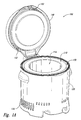
- Figures 1A and 1B are isometric views of a kiln configured in accordance with an embodiment of the invention
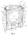
- Figure 2 is an isometric cross-sectional view of the kiln of Figures 1A and 1B .
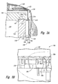
- Figure 3A is an enlarged, side cross-sectional view taken from the area 3A of Figure 2 illustrating several aspects of the invention.
- Figure 3B is an enlarged, side cross-sectional view taken from the area 3B of Figure 2 illustrating other aspects of the invention
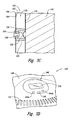
- Figure 3C is an enlarged, side cross-sectional view taken from the area 3C of Figure 2 illustrating further aspects of the invention
- Figure 3D is an enlarged, isometric view taken from the area 3D of Figure 1B illustrating yet another aspect of the invention.
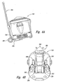
- Figure 4A is a side view and Figure 4B is a bottom isometric view of the kiln of Figures 1A-3D and a kiln transport assembly configured in accordance with an embodiment of the invention.
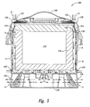
- Figure 5 is a side cross-sectional view of the Kiln of Figures 1A-3D illustrating various aspects of several embodiments for cooling the kiln during operation
- Figures 1A and 1B are isometric views of a kiln 100 configured in accordance with an embodiment of the invention
- the kiln 100 can include an inner body 110 configured to hold one or more ceramic workpieces (not shown), and an outer body 120 at least partially surrounding the inner body 110.
- the outer body 120 is spaced apart from the inner body 110 to define an airflow passageway 130 therebetween
- the kiln 100 can further include a lid assembly 140 pivotably coupled to the outer body 120.
- the lid assembly 140 can be configured to sealably close against the inner body 110 and, in at least several embodiments, the outer body 120.
- the lid assembly 140 is illustrated in an open position to provide access to a processing chamber 114.
- the lid assembly 140 is sealably closed against the inner body 110 and at least a portion of the outer body 120 for workpiece processing.
- the kiln 100 includes an air inlet 132 in the lid assembly 140 and an air outlet 134 in the outer body 120.
- the Inlet 132 and outlet 134 are in fluid communication with the airflow passageway 130 ( Figure 1A ).
- the kiln 100 further includes an air mover configured to move ambient air through the airflow passageway 130 from the inlet 132 toward the outlet 134 to maintain the surface temperature of the outer body 120 at or below a preset temperature during operation of the kiln 100
- the surface temperature of the outer body 120 can remain cool to the touch, while the processing chamber 114 is heated to over 982 ⁇ 2°C for workpiece processing.
- Various features of several embodiments of the system for cooling the inner body 110 are described in greater detail below with reference to Figures 2-5 .
- FIG 2 is an isometric cross-sectional view of the kiln 100 of Figures 1A and 1B .
- the inner body 110 includes an inner wall 112 defining the processing chamber 114 for ceramic workpieces (not shown).
- the inner body 110 further includes an outer wall 116 that faces the outer body 120.
- the inner body 110 can include a refractory material that is configured to withstand the high temperatures necessary to process the ceramic workpiece and the drastic changes in temperature throughout the processing cycle.
- the thickness of the inner body 110 i.e., the distance between the inner wall 112 and the outer wall 116) can vary depending on the desired operational parameters for the kiln 100 and/or the material used to form the inner body 110.
- the lid assembly 140 further includes an inner body lid portion 146 configured to releasably engage or otherwise mate with the inner body 110 to sealably close the processing chamber 114.
- the inner body lid portion 146 can include a first chamfered portion 147 configured to mate with a second chamfered portion 117 of the inner body 110 to seal the processing chamber 114 when the lid assembly 140 is closed (as illustrated in Figure 2 ).
- One advantage of the relatively large surface area of the interface between the sidewall of the inner body 110 and the inner body lid portion 146 is that the chamfered interface can minimize heat loss from the processing chamber 114 during operation as compared with processing chambers that include non-chamfered interfaces.
- the inner body lid portion 146 carried by the lid assembly 140 can be slightly adjustable (e.g., it can "float” or move horizontally and/or vertically) relative to the lid assembly 140 and the inner body 110, thereby allowing the first chamfered interface portion 147 of the inner body lid portion 146 to more accurately and tightly seat against the second chamfered interface portion 117 of the inner body 110.
- the kiln 100 includes a first radiant barrier 160 positioned in the airflow passageway 130 between the inner body 110 and the outer body 120, and a second radiant barrier 168 carried by the lid assembly 140.
- the first radiant barrier 160 can include a first side 162 facing the outer wall 116 of the inner body 110 and a second side 164 facing the outer body 120.
- the first radiant barrier 160 defines (a) a first portion 136 of the airflow passageway 130 between the inner body 110 and the first side 162 of the first radiant barrier 160, and (b) a second portion 138 of the airflow passageway 130 between the second side 164 of the first radiant barrier 160 and the outer body 120. Further details regarding the first and second portions 136 and 138 of the airflow passageway 130 are described below with respect to Figure 5 .
- the second radiant barrier 168 is spaced apart from the inner body lid portion 146.
- the first side 162 of the first radiant barrier 160 and the lower side of the second radiant barrier 168 facing the inner body lid portion 146 can each include a polished, highly reflective surface.
- the first radiant barrier 160 can also include a plurality of fins 166 projecting from the first side 162 of the first radiant barrier 160 toward the outer wall 116 of the inner body 110. The fins 166 are positioned to create an area of low pressure within the first portion 136 of the airflow passageway 130 to help increase the flow of air within this portion of the airflow passageway 130.
- the first and second radiant barriers 160 and 168 can include different features and/or have other arrangements depending on a number of different factors including manufacturing cost, operating temperatures, etc.
- the kiln 100 includes an air mover 170 (e.g., a fan) positioned to move air through the airflow passageway 130 from the inlet 132 toward the outlet 134.
- the air mover 170 is located proximate to a lower portion of the kiln 100 in communication with the airflow passageway 130. In other embodiments, however, the air mover 170 can be positioned at different locations and/or have different configurations.
- the kiln 100 can further include a battery 182 operably coupled to the air mover 170 and/or other kiln systems (not shown).
- the battery 182 is configured to power the air mover 170 and various controls of the kiln 100 in the event of an external power failure while the kiln 100 is processing the ceramic workpiece.
- the battery 182 is a back-up feature that allows the air mover 170 to continue cooling the inner body 110 and maintain the outer body 120 at or below a preset temperature until processing is complete.
- the kiln 100 can include a debris screen 180 positioned proximate to the Inlet 132 of the airflow passageway 130,
- the debris screen 180 includes a number of apertures configured to allow air to pass, but prevents large particulates or other undesirable materials from entering the airflow passageway 130.
- the debris screen 180 may have a different configuration or be positioned at a different location.
- the debris screen 180 can be omitted.
- Figure 3A is an enlarged, side cross-sectional view taken from the area 3A of Figure 2 illustrating several aspects of the invention.
- the first radiant barrier 160 includes an upper edge portion 310
- the second radiant barrier 168 includes a lower edge portion 312 spaced apart from the upper edge portion 310 to define an offset 314 between the two structures
- the offset 314 is configured to cause additional ambient air to flow into the first portion 138 of the airflow passageway 130 to further cool the inner body 110 during klin operation.
- the offset 314 can have a different arrangement and/or dimension or be omitted.
- FIG. 3B is an enlarged, side cross-sectional view taken from the area 3B of Figure 2 illustrating another aspect of the invention.
- the kiln 100 includes a latch assembly 320 configured to releasably secure the lid assembly 140 in a closed position during processing.
- the latch assembly 320 can include, for example, a solenoid mechanism 322 to toggle a pin 324 between an unlocked position (shown in broken lines) and a locked position (shown in solid lines). In the locked position, the pin 324 engages a catch 326 to restrain the lid assembly 140 in a closed position.
- the latch assembly 320 can be operably coupled to a controller (not shown) that causes the pin 324 to remain in the locked position while the kiln 100 is operational (e.g., when the temperature in the processing chamber 114 is above a preset temperature, such as 54 ⁇ 4°C.
- the latch assembly 320 can have a different configuration (e.g., the latch assembly may have a generally vertical orientation rather than the generally horizontal orientation in the illustrated embodiment) and/or the latch assembly 320 may include different features.
- Figure 3C is an enlarged, side cross-sectional view taken from the area 3C of Figure 2 illustrating one method for attaching the inner body 110 to the first radiant barrier 160.
- the inner body 110 includes a plurality of protrusions or dimples 330 (only one is shown) projecting away from the outer wall 116 of the inner body 110 toward the first side 162 of the first radiant barrier 160.
- a plurality of spacers 332 (only one is shown) can be engaged with corresponding protrusions 330 to releasably attach the inner body 110 to the first radiant barrier 160.
- Each spacer 332 can include, for example, a generally cylindrical riser portion 336 at least partially surrounding the corresponding protrusion 330 and an engagement feature 334 configured to mate with or otherwise engage the protrusion 330.
- the riser portion 336 can be formed from a material that generally prevents thermal transfer between the inner body 110 and the first radiant barrier 160.
- the riser portion 336 can be releasably secured to the first radiant barrier 160 with a fastener 338.
- FIG 3D is an enlarged isometric view taken from the area 3D of Figure 1B illustrating still another aspect of the invention.
- the lid assembly 140 can include a user interface 340 for controlling operation of the kiln 100.
- the user interface 340 can include, for example, a power button 342 to power the kiln 100 on and off and one or more selector buttons 344 (two are shown in Figure 1B as 344a and 344b) to activate various functions of the kiln 100, such as starting/canceling the glazing process and unlocking the lid assembly 140.
- the user interface 340 further includes a display 346 to provide feedback to the user regarding the current operational status of the kiln 100, such as temperature, time, etc.
- the user interface 340 can include different features and/or the features may have a different arrangement.
- Figure 4A is a side view and Figure 4B is a bottom isometric view of the kiln of Figures 1A-3D and a kiln transport assembly 360 configured in accordance with an embodiment of the invention.
- the kiln 100 includes an interface portion 350 configured to releasably receive a portion of the kiln transport assembly 360.
- the kiln transport assembly 360 is a hand truck with engagement members 362 received within the interface portion 350 of the kiln, a vertical frame 364 with one or more handles at an upper portion of the frame 364, and a set of wheels 366.
- the kiln transport assembly 360 Using the kiln transport assembly 360, a user (not shown) can readily move the kiln 100 from one location to another location either before or after processing. Compared with the large and relatively cumbersome conventional kilns described previously, the kiln 100 can be relatively easy to move from one location to another. Additionally, during normal operation of the kiln 100, the kiln transport assembly 360 can be disengaged from the kiln 100 and stored separately. In other embodiments, the kiln 100 may include one or more sets of wheels attached to the outer body 120 in addition to (or in lieu of) the wheels 366 of the kiln transport assembly 360. In still further embodiments, the kiln 100 can include a permanent or at least partially permanent transport assembly rather than the removable kiln transport assembly 360 described above.
- FIG. 5 is a side cross-sectional view of the kiln 100 of Figures 1A-3D illustrating various functional aspects of the kiln during operation.
- the air mover 170 is configured to move ambient air (as shown by the arrows A) through the airflow passageway 130 from the inlet 132 toward the outlet 134. More specifically, after passing through the inlet 132, the air flow A moves into both the first portion 136 and the second portion 138 of the airflow passageway 130.
- the first portion 136 of the airflow passageway 130 is closer in proximity to the inner body 110 than the second portion 138 and, therefore, the first portion 136 of the airflow passageway 130 is generally at a higher temperature than the second portion 138 of the airflow passageway.
- the air flow A passing through the first portion 136 is accordingly heated to a higher temperature than the air flow A passing through the second portion 138 of the airflow passageway.
- the offset 314 (discussed in detail above with respect to Figure 3A ) is configured to increase or supplement the flow of cooler ambient air into the first portion 136 of the airflow passageway 130 to help cool the inner body 110.
- the kiln 100 can further include a plurality of supplemental air intake portions 410 in the outer body 120 and generally aligned with a lower portion of the inner body 110.
- the air intake portions 410 are in fluid communication with the airflow passageway 130.
- an additional volume of cooler ambient air can flow through the air intake portions 410 into the airflow passageway 130 and mix with the exhaust air passing out of the first and second portions 136 and 138 of the airflow passageway 130 and toward the air mover 170. In this way, the air flow A is cooled before being exhausted from the outlet portions 134.
- One feature of at least some of the embodiments of the kiln 100 described above with respect to Figures 1A-5 is that the outer body 120 of the kiln 100 is kept relatively cool during operation.
- One advantage of this feature is that the kiln 100 can be used in a variety of environments (e.g., home or personal use) where higher temperatures would be undesirable.
- the exterior surfaces of conventional kilns can become relatively hot during operation and, accordingly, such kilns are generally unsuitable for home use.
- the kiln is portable and relatively small as compared with conventional kilns.
- the kiln transport assembly 360 can be used to move the kiln 100 from a first location to a second location with relative ease.
- Still another feature of at least some embodiments of the kiln 100 is the relatively small size of the kiln as compared with conventional kilns.
- the kiln can include a different number of air movers and/or the air movers may be positioned at different locations within the kiln.
- the kiln 100 can be configured to process glass, jewelry, and/or other related materials in addition to (or in lieu of) ceramic materials. Aspects of the invention described in the context of particular embodiments may be combined or eliminated in other embodiments.
Landscapes
- Engineering & Computer Science (AREA)
- Mechanical Engineering (AREA)
- General Engineering & Computer Science (AREA)
- Muffle Furnaces And Rotary Kilns (AREA)
- Furnace Details (AREA)
- Electric Stoves And Ranges (AREA)
Description
- The present invention is directed generally toward kilns for processing ceramics and, more particularly, to portable kilns for use in the home environment:
- Kilns as described in
DE 29600841U1 ,GB 1466999A1 DE7704066U1 can be used to harden, bum, and/or dry a number of different materials in one common application, for example. kilns are used in the production of ceramics. This process, generally referred to as "firing," can include chemically refining clay objects by heating them until a crystalline matrix of silica and alumina forms, thus making the resulting ceramic articles hard and durable. Depending on the size, complexity, and desired finish of the ceramic articles, this process can take a significant amount of time. - to fire a ceramic workpiece in a kiln, the temperature of an internal processing chamber is raised to a relatively high temperature (e.g., 982·2°C (1800°F), maintained at that temperature for a given period of time to adequately heat the clay object until the clay develops the desired properties, and then cooled relatively quickly so that the ceramic workpieces can be retrieved from the processing chamber and the kiln can be used to process another workpiece. Because of the high temperatures involved, conventional kilns typically Include relatively thick insulating sidewalls and extensive cooling systems. As a result these kilns are large and cumbersome, relatively expensive, and generally unsuitable for home or personal use. Moreover, the exterior surfaces of such kilns can still become relatively hot during operation, thus making the kilns undesirable for in-home or personal use.
- The invention is defined in the claims. The following summary is provided for the benefit of the reader only and does not limit the invention. Aspects of the invention according to the claims are directed generally to portable kilns or other types of kilns for processing ceramics A kiln configured in accordance with one embodiment of the invention includes an inner body configured to hold one or more ceramic workpieces for processing The kiln also includes an outer body at least partially surrounding the inner body and spaced apart from the inner body to define an airflow passageway therebetween. The airflow passageway includes an inlet proximate to an upper portion of the outer body and an outlet proximate to a lower portion of the outer body The kiln further inciudes an air mover positioned to move air through the airflow passageway from the inlet toward the outlet In several embodiments, the kiln can additionally include a lid assembly pivotably coupled to the outer body and configured to sealably close against at least the inner body.
- A kiln configured in accordance with the invention includes an inner body configured to hold one or more ceramic workpieces for processing, and an outer body spaced apart from the inner body to define an airflow passageway therebetween. The airflow passageway includes an inlet proximate to an upper portion of the outer body and an outlet proximate to a lower portion of the outer body The kiln can also include a lid assembly operably coupled to the outer body and configured to sealably close against at least the inner body. The kiln further includes a radiant barrier positioned in the airflow passageway between the inner body and the outer body, and a fan positioned proximate to the lower portion of the outer body. The fan is positioned to move air through the airflow passageway from the inlet toward the outlet to cool the inner body during processing of the ceramic workpieces.
- A method for processing ceramics In accordance with a further aspect of the invention includes placing a ceramic workpiece into a processing chamber of a kiln and increasing the temperature in the processing chamber to process the ceramic workpiece. The method also includes flowing air from an inlet positioned proximate to an upper portion of the kiln through a passageway extending at least partially around the processing chamber to maintain the temperature of an exterior portion of the kiln at or below a preset temperature. The method further includes reflecting at least a portion of the heat generated by the processing chamber back toward the inner body using a radiant barrier positioned in the airflow passageway.
-
Figures 1A and1B are isometric views of a kiln configured in accordance with an embodiment of the invention -
Figure 2 is an isometric cross-sectional view of the kiln ofFigures 1A and1B . -
Figure 3A is an enlarged, side cross-sectional view taken from thearea 3A ofFigure 2 illustrating several aspects of the invention. -
Figure 3B is an enlarged, side cross-sectional view taken from thearea 3B ofFigure 2 illustrating other aspects of the invention -
Figure 3C is an enlarged, side cross-sectional view taken from thearea 3C ofFigure 2 illustrating further aspects of the invention -
Figure 3D is an enlarged, isometric view taken from thearea 3D ofFigure 1B illustrating yet another aspect of the invention. -
Figure 4A is a side view andFigure 4B is a bottom isometric view of the kiln ofFigures 1A-3D and a kiln transport assembly configured in accordance with an embodiment of the invention. -
Figure 5 is a side cross-sectional view of the Kiln ofFigures 1A-3D illustrating various aspects of several embodiments for cooling the kiln during operation - The following disclosure describes various aspects of kilns and other heating devices for processing ceramics, glazes, and/or other related materials. Certain details are set forth in the following description and in
Figures 1A-5 to provide a thorough understanding of various embodiments of the invention. Well-known structures, systems and methods often associated with kilns and related systems, however, have not been shown or described in detail below to avoid unnecessarily obscuring the description of the various embodiments of the invention. Any dimensions, angles, and other specifications shown in the Figures are merely illustrative of particular embodiments of the invention. Accordingly, other embodiments of the invention can have other dimensions, angles, and specifications without departing from the scope of the present disclosure. In addition, those of ordinary skill in the relevant art will understand that additional embodiments of the invention may be practiced without several of the details described below. -
Figures 1A and1B are isometric views of akiln 100 configured in accordance with an embodiment of the invention Referring toFigure 1A , thekiln 100 can include aninner body 110 configured to hold one or more ceramic workpieces (not shown), and anouter body 120 at least partially surrounding theinner body 110. Theouter body 120 is spaced apart from theinner body 110 to define anairflow passageway 130 therebetween Thekiln 100 can further include alid assembly 140 pivotably coupled to theouter body 120. Thelid assembly 140 can be configured to sealably close against theinner body 110 and, in at least several embodiments, theouter body 120. InFigure 1A , thelid assembly 140 is illustrated in an open position to provide access to aprocessing chamber 114. InFigure 1B thelid assembly 140 is sealably closed against theinner body 110 and at least a portion of theouter body 120 for workpiece processing. - Referring to
Figures 1A and1B together, thekiln 100 includes anair inlet 132 in thelid assembly 140 and anair outlet 134 in theouter body 120. The Inlet 132 andoutlet 134 are in fluid communication with the airflow passageway 130 (Figure 1A ). As described in detail below with reference toFigure 2 , thekiln 100 further includes an air mover configured to move ambient air through theairflow passageway 130 from theinlet 132 toward theoutlet 134 to maintain the surface temperature of theouter body 120 at or below a preset temperature during operation of thekiln 100 For example, in one embodiment, the surface temperature of theouter body 120 can remain cool to the touch, while theprocessing chamber 114 is heated to over 982·2°C for workpiece processing. Various features of several embodiments of the system for cooling theinner body 110 are described in greater detail below with reference toFigures 2-5 . -
Figure 2 is an isometric cross-sectional view of thekiln 100 ofFigures 1A and1B . Theinner body 110 includes aninner wall 112 defining theprocessing chamber 114 for ceramic workpieces (not shown). Theinner body 110 further includes anouter wall 116 that faces theouter body 120. Theinner body 110 can include a refractory material that is configured to withstand the high temperatures necessary to process the ceramic workpiece and the drastic changes in temperature throughout the processing cycle. The thickness of the inner body 110 (i.e., the distance between theinner wall 112 and the outer wall 116) can vary depending on the desired operational parameters for thekiln 100 and/or the material used to form theinner body 110. - The
lid assembly 140 further includes an innerbody lid portion 146 configured to releasably engage or otherwise mate with theinner body 110 to sealably close theprocessing chamber 114. In the illustrated embodiment, the innerbody lid portion 146, can include afirst chamfered portion 147 configured to mate with a second chamferedportion 117 of theinner body 110 to seal theprocessing chamber 114 when thelid assembly 140 is closed (as illustrated inFigure 2 ). One advantage of the relatively large surface area of the interface between the sidewall of theinner body 110 and the innerbody lid portion 146 is that the chamfered interface can minimize heat loss from theprocessing chamber 114 during operation as compared with processing chambers that include non-chamfered interfaces. In a further aspect of this embodiment, the innerbody lid portion 146 carried by thelid assembly 140 can be slightly adjustable (e.g., it can "float" or move horizontally and/or vertically) relative to thelid assembly 140 and theinner body 110, thereby allowing the firstchamfered interface portion 147 of the innerbody lid portion 146 to more accurately and tightly seat against the secondchamfered interface portion 117 of theinner body 110. - In another aspect of this embodiment, the
kiln 100 includes a firstradiant barrier 160 positioned in theairflow passageway 130 between theinner body 110 and theouter body 120, and a secondradiant barrier 168 carried by thelid assembly 140. The firstradiant barrier 160 can include afirst side 162 facing theouter wall 116 of theinner body 110 and asecond side 164 facing theouter body 120. The firstradiant barrier 160 defines (a) afirst portion 136 of theairflow passageway 130 between theinner body 110 and thefirst side 162 of the firstradiant barrier 160, and (b) asecond portion 138 of theairflow passageway 130 between thesecond side 164 of the firstradiant barrier 160 and theouter body 120. Further details regarding the first andsecond portions airflow passageway 130 are described below with respect toFigure 5 . The secondradiant barrier 168 is spaced apart from the innerbody lid portion 146. - In one embodiment, the
first side 162 of the firstradiant barrier 160 and the lower side of the secondradiant barrier 168 facing the innerbody lid portion 146 can each include a polished, highly reflective surface. One advantage of this feature is that the reflective surface can help maintain the temperature of theouter body 120 at an acceptable level by reflecting heat from theinner body 110 back toward the inner body during kiln operation. The firstradiant barrier 160 can also include a plurality offins 166 projecting from thefirst side 162 of the firstradiant barrier 160 toward theouter wall 116 of theinner body 110. Thefins 166 are positioned to create an area of low pressure within thefirst portion 136 of theairflow passageway 130 to help increase the flow of air within this portion of theairflow passageway 130. In other embodiments, the first and secondradiant barriers - As mentioned previously, the
kiln 100 includes an air mover 170 (e.g., a fan) positioned to move air through theairflow passageway 130 from theinlet 132 toward theoutlet 134. In the embodiment illustrated inFigure 2 , theair mover 170 is located proximate to a lower portion of thekiln 100 in communication with theairflow passageway 130. In other embodiments, however, theair mover 170 can be positioned at different locations and/or have different configurations. In several embodiments, thekiln 100 can further include abattery 182 operably coupled to theair mover 170 and/or other kiln systems (not shown). Thebattery 182 is configured to power theair mover 170 and various controls of thekiln 100 in the event of an external power failure while thekiln 100 is processing the ceramic workpiece. In this regard, thebattery 182 is a back-up feature that allows theair mover 170 to continue cooling theinner body 110 and maintain theouter body 120 at or below a preset temperature until processing is complete. - in still another aspect of this embodiment, the
kiln 100 can include adebris screen 180 positioned proximate to theInlet 132 of theairflow passageway 130, Thedebris screen 180 includes a number of apertures configured to allow air to pass, but prevents large particulates or other undesirable materials from entering theairflow passageway 130. In other embodiments, thedebris screen 180 may have a different configuration or be positioned at a different location. In still other embodiments, thedebris screen 180 can be omitted. -
Figure 3A is an enlarged, side cross-sectional view taken from thearea 3A ofFigure 2 illustrating several aspects of the invention. As this view illustrates, the firstradiant barrier 160 includes anupper edge portion 310, and the secondradiant barrier 168 includes alower edge portion 312 spaced apart from theupper edge portion 310 to define an offset 314 between the two structures, The offset 314 is configured to cause additional ambient air to flow into thefirst portion 138 of theairflow passageway 130 to further cool theinner body 110 during klin operation. In other embodiments, the offset 314 can have a different arrangement and/or dimension or be omitted. -
Figure 3B is an enlarged, side cross-sectional view taken from thearea 3B ofFigure 2 illustrating another aspect of the invention. In this embodiment, thekiln 100 includes a latch assembly 320 configured to releasably secure thelid assembly 140 in a closed position during processing. The latch assembly 320 can include, for example, asolenoid mechanism 322 to toggle apin 324 between an unlocked position (shown in broken lines) and a locked position (shown in solid lines). In the locked position, thepin 324 engages acatch 326 to restrain thelid assembly 140 in a closed position. The latch assembly 320 can be operably coupled to a controller (not shown) that causes thepin 324 to remain in the locked position while thekiln 100 is operational (e.g., when the temperature in theprocessing chamber 114 is above a preset temperature, such as 54·4°C. In other embodiments, the latch assembly 320 can have a different configuration (e.g., the latch assembly may have a generally vertical orientation rather than the generally horizontal orientation in the illustrated embodiment) and/or the latch assembly 320 may include different features. -
Figure 3C is an enlarged, side cross-sectional view taken from thearea 3C ofFigure 2 illustrating one method for attaching theinner body 110 to the firstradiant barrier 160. In the illustrated embodiment, theinner body 110 includes a plurality of protrusions or dimples 330 (only one is shown) projecting away from theouter wall 116 of theinner body 110 toward thefirst side 162 of the firstradiant barrier 160. A plurality of spacers 332 (only one is shown) can be engaged withcorresponding protrusions 330 to releasably attach theinner body 110 to the firstradiant barrier 160. Eachspacer 332 can include, for example, a generallycylindrical riser portion 336 at least partially surrounding the correspondingprotrusion 330 and anengagement feature 334 configured to mate with or otherwise engage theprotrusion 330. Theriser portion 336 can be formed from a material that generally prevents thermal transfer between theinner body 110 and the firstradiant barrier 160. Theriser portion 336 can be releasably secured to the firstradiant barrier 160 with afastener 338. An advantage of this feature is that thespacer 332 is configured to allow some minor relative movement between theinner body 110 and the firstradiant barrier 160 during processing, while preventing thermal transfer between the two structures. -
Figure 3D is an enlarged isometric view taken from thearea 3D ofFigure 1B illustrating still another aspect of the invention. As this view illustrates, thelid assembly 140 can include auser interface 340 for controlling operation of thekiln 100. Theuser interface 340 can include, for example, apower button 342 to power thekiln 100 on and off and one or more selector buttons 344 (two are shown inFigure 1B as 344a and 344b) to activate various functions of thekiln 100, such as starting/canceling the glazing process and unlocking thelid assembly 140. Theuser interface 340 further includes adisplay 346 to provide feedback to the user regarding the current operational status of thekiln 100, such as temperature, time, etc. In other embodiments, theuser interface 340 can include different features and/or the features may have a different arrangement. -
Figure 4A is a side view andFigure 4B is a bottom isometric view of the kiln ofFigures 1A-3D and akiln transport assembly 360 configured in accordance with an embodiment of the invention. Referring toFigures 4A and 4B together, thekiln 100 includes aninterface portion 350 configured to releasably receive a portion of thekiln transport assembly 360. In the illustrated embodiment, for example, thekiln transport assembly 360 is a hand truck withengagement members 362 received within theinterface portion 350 of the kiln, avertical frame 364 with one or more handles at an upper portion of theframe 364, and a set ofwheels 366. Using thekiln transport assembly 360, a user (not shown) can readily move thekiln 100 from one location to another location either before or after processing. Compared with the large and relatively cumbersome conventional kilns described previously, thekiln 100 can be relatively easy to move from one location to another. Additionally, during normal operation of thekiln 100, thekiln transport assembly 360 can be disengaged from thekiln 100 and stored separately. In other embodiments, thekiln 100 may include one or more sets of wheels attached to theouter body 120 in addition to (or in lieu of) thewheels 366 of thekiln transport assembly 360. In still further embodiments, thekiln 100 can include a permanent or at least partially permanent transport assembly rather than the removablekiln transport assembly 360 described above. -
Figure 5 is a side cross-sectional view of thekiln 100 ofFigures 1A-3D illustrating various functional aspects of the kiln during operation. In the illustrated embodiment, theair mover 170 is configured to move ambient air (as shown by the arrows A) through theairflow passageway 130 from theinlet 132 toward theoutlet 134. More specifically, after passing through theinlet 132, the air flow A moves into both thefirst portion 136 and thesecond portion 138 of theairflow passageway 130. Thefirst portion 136 of theairflow passageway 130 is closer in proximity to theinner body 110 than thesecond portion 138 and, therefore, thefirst portion 136 of theairflow passageway 130 is generally at a higher temperature than thesecond portion 138 of the airflow passageway. The air flow A passing through thefirst portion 136 is accordingly heated to a higher temperature than the air flow A passing through thesecond portion 138 of the airflow passageway. - In one aspect of this embodiment, the offset 314 (discussed in detail above with respect to
Figure 3A ) is configured to increase or supplement the flow of cooler ambient air into thefirst portion 136 of theairflow passageway 130 to help cool theinner body 110. In another aspect of this embodiment, thekiln 100 can further include a plurality of supplementalair intake portions 410 in theouter body 120 and generally aligned with a lower portion of theinner body 110. Theair intake portions 410 are in fluid communication with theairflow passageway 130. In operation, an additional volume of cooler ambient air can flow through theair intake portions 410 into theairflow passageway 130 and mix with the exhaust air passing out of the first andsecond portions airflow passageway 130 and toward theair mover 170. In this way, the air flow A is cooled before being exhausted from theoutlet portions 134. - One feature of at least some of the embodiments of the
kiln 100 described above with respect toFigures 1A-5 is that theouter body 120 of thekiln 100 is kept relatively cool during operation. One advantage of this feature is that thekiln 100 can be used in a variety of environments (e.g., home or personal use) where higher temperatures would be undesirable. In contrast, as discussed above, the exterior surfaces of conventional kilns can become relatively hot during operation and, accordingly, such kilns are generally unsuitable for home use. - Another feature of at least some of the embodiments of the
kiln 100 described above is that the kiln is portable and relatively small as compared with conventional kilns. For example, thekiln transport assembly 360 can be used to move thekiln 100 from a first location to a second location with relative ease. Still another feature of at least some embodiments of thekiln 100 is the relatively small size of the kiln as compared with conventional kilns. An advantage of these features is that it can reduce the time and cost associated with the production and processing of ceramic articles because a user can perform the firing processes at home using thekiln 100, rather than having to take the ceramic articles to be processed in a commercial-grade kiln. - From the foregoing, it will be appreciated that specific embodiments of the invention have been described herein for purposes of illustration, but that various modifications may be made without deviating from the invention. For example, the kiln can include a different number of air movers and/or the air movers may be positioned at different locations within the kiln. Additionally, in several embodiments the
kiln 100 can be configured to process glass, jewelry, and/or other related materials in addition to (or in lieu of) ceramic materials. Aspects of the invention described in the context of particular embodiments may be combined or eliminated in other embodiments. Further, while advantages associated with certain embodiments of the invention have been described in the context of those embodiments, other embodiments may also exhibit such advantages, and not all embodiments need necessarily exhibit such advantages to fall within the scope of the invention. Accordingly, the invention is not limited except as by the appended claims.
Claims (34)
- A kiln (100), comprising:an inner body (110) configured to hold one or more ceramic workpieces for processing;an outer body (120) at least partially surrounding the inner body (110) and spaced apart from the inner body (110) to define an airflow passageway (130) therebetween, the airflow passageway (130) having an inlet (132) proximate to an upper portion of the outer body (120) and an outlet (134) proximate to a lower portion of the outer body (120);a radiant barrier (160) positioned in the airflow passageway (130) between the inner body (110) and the outer body (120), the radiant barrier (160) including a first side (162) facing the inner body (110) and a second side (164) facing the outer body (120); andan air mover (170) positioned to move ambient air through the airflow passageway (130) from the inlet (132) toward the outlet (134).
- The kiln (100) of claim 1, further comprising a lid assembly (140) pivotably coupled to the outer body (120) and configured to sealably close against at least the inner body (110).
- The kiln (100) of claim 1 wherein the lid assembly (140) includes at least a portion of the inlet (132) of the airflow passageway (130).
- The kiln (100) of claim 1, further comprising a latch assembly (320) configured to releasably secure the lid assembly (140) in a closed position when the temperature in the inner body (110) is above a preset temperature.
- The kiln (100) of claim 1 wherein:the lid assembly (140) has a first chamfered interface portion (147); andthe inner body (110) has second chamfered interface portion (117) configured to cooperate with the first chamfered interface portion (147) to seal the inner body (110) when the lid assembly (140) is closed.
- The kiln (100) of claim 1 wherein the radiant barrier (160) defines (a) a first portion (136) of the airflow passageway (130) between the inner body (110) and the first side (162) of the radiant barrier (160), and (b) a second portion (138) of the airflow passageway (130) between the second side (164) of the radiant barrier (160) and the outer body (120).
- The kiln (100) of claim 6 wherein the first portion (136) of the airflow passageway (130) is adapted to operate at a first temperature and the second portion (138) of the airflow passageway (130) is adapted to operate at a second temperature less than the first temperature.
- The kiln (100) of claim 1 wherein the inlet (132) is a first inlet (132) and the radiant barrier (160) is a first radiant barrier (160), and wherein the kiln further comprises:a lid assembly (140) pivotably coupled to the outer body (120) and positioned to sealably close against the inner body (110) and outer body (120); anda second radiant barrier (168) carried by the lid assembly (140), wherein the second radiant barrier (168) is laterally offset from the first radiant barrier (160) when the lid assembly (140) is closed to define a second inlet positioned to draw additional air into the airflow passageway (130).
- The kiln (100) of claim 1 wherein the inlet (132) is a first inlet (132) and the radiant barrier (160) is a first generally cylindrical radiant barrier (160) having a first diameter, and wherein the kiln (100) further comprises:a lid assembly (140) pivotably coupled to the outer body (120) and positioned to sealably close against the inner body (110) and outer body (120); anda second generally cylindrical radiant barrier (168) carried by the lid assembly (140), the second radiant barrier (168) having a second diameter less than the first diameter to define a second inlet positioned to draw additional air into the airflow passageway (130) when the lid assembly (140) is closed.
- The kiln (100) of claim 1 wherein the radiant barrier (160) further comprises a plurality of fins (166) projecting from the first side (162) of the radiant barrier (160) toward the inner body (110).
- The kiln (100) of claim 1 wherein the first side (162) of the radiant barrier (160) includes a highly reflective surface.
- The kiln (100) of claim 1 wherein the inner body (110) comprises a refractory position.
- The kiln (100) of claim 1 wherein the outer body (120) is configured to releasably receive a kiln transport assembly (360).
- The kiln (100) of claim 1 wherein the air mover (170) is positioned proximate to the lower portion of the outer body (120).
- The kiln (100) of claim 14 wherein the air mover (170) is centrally located beneath the inner body (110).
- The kiln (100) of claim 1, further comprising a plurality of air intake portions (410) in the outer body (120) adjacent to a lower portion of the inner body (110), the air intake portions (410) being in fluid communication with the airflow passageway (130).
- The kiln (100) of claim 1, further comprising a debris screen (180) positioned proximate the inlet (132) of the airflow passageway (130).
- A kiln (100) according to any of claims 1, 3 or 4 further comprising:a lid assembly (140) operably coupled to the outer body (120) and configured to sealably close against at least the inner body (110); andwherein the air mover (170) comprises:a fan proximate to the lower portion of the outer body (120) and positioned to move ambient air through the airflow passageway (130) from the inlet (132) toward the outlet (134) to cool the inner body (110) during processing of the one or more ceramic workpieces placed therein.
- The kiln (100) of claim 18 wherein:the lid assembly (140) includes a lower edge portion (146) and a first chamfered portion (147) at the lower edge portion (146); andthe inner body (110) includes a sidewall having an upper edge portion and a second chamfered portion (117) at the upper edge portion, the second chamfered portion (117) being configured to cooperate with the first chamfered portion (147) to seal the inner body (110) when the lid assembly (140) is closed.
- The kiln (100) of claim 18 wherein the radiant barrier (160) includes a first side (162) facing the inner body (110) and a second side (164) facing the outer body (120), the radiant barrier (160) defining (a) a first portion (136) of the airflow passageway (130) between the inner body (110) and the first side (162) of the radiant barrier (160), and (b) a second portion (138) of the airflow passageway (130) between the second side (164) of the radiant barrier (160) and the outer body (120).
- The kiln (100) of claim 20 wherein the first portion (136) of the airflow passageway (130) is adapted to operate at a first temperature and the second portion (138) of the airflow passageway (130) is adapted to operate at a second temperature less than the first temperature.
- The kiln (100) of claim 18 wherein the inlet (132) is a first inlet (132) and the radiant barrier (160) is a first radiant barrier (160) and wherein the kiln (100) further comprises:a second radiant barrier (168) carried by the lid assembly (140), wherein the second radiant barrier (168) is laterally offset from the first radiant barrier (160) when the lid assembly (140) is closed to thereby define a second inlet positioned to draw additional air into the airflow passageway (130) to cool the inner body (110).
- The kiln (100) of claim 18 wherein the first side (162) of the radiant barrier (160) has a first level of reflectivity and the second side (164) has a second level of reflectivity less than the first level.
- The kiln (100) of claim 18 wherein the outer body (120) includes an interface portion (350) configured to receive a portion of a kiln transport assembly (360).
- The kiln (100) of claim 18 wherein the outer body (120) includes one or more channels configured to releasably receive an engagement member (362) of a kiln transport assembly (360).
- A kiln (100) according to any preceding claim wherein the inner body (110) is a ceramic processing chamber (114).
- The kiln (100) of claim 26 wherein the radiant barrier (160) defines (a) a first portion (136) of the airflow passageway (130) between the processing chamber (114) and the first side (162) of the radiant barrier (160), and (b) a second portion (138) of the airflow passageway (130) between the second side (164) of the radiant barrier and the outer body (120).
- The kiln (100) of claim 27 wherein the first portion (136) of the airflow passageway (130) is adapted to operate at a first temperature and the second portion (138) of the airflow passageway (130) is adapted to operate at a second temperature less than the first temperature.
- The kiln (100) of claim 26 wherein the airflow means (170) includes a fan proximate to the lower portion of the outer body (120) and positioned to move air through the airflow passageway (130) from the air inlet (132) toward the air outlet (134).
- A method for processing ceramics, the method comprising:placing a ceramic workpiece into a processing chamber (114) of the kiln (100) according to any of claims 26 to 29;increasing the temperature in the processing chamber (114) to process the ceramic workpiece;reflecting at least a portion of the heat generated by the processing chamber (114) during processing back toward the inner body (110) using the radiant barrier (160) positioned in the airflow passageway (130); andflowing ambient air from an inlet (132) positioned proximate to an upper portion of the kiln (100) through a passageway (130) extending at least partially around the processing chamber (114) to maintain the temperature of an exterior portion of the kiln (100) at or below a preset temperature.
- The method of claim 30 wherein increasing the temperature within the processing chamber (114) includes the temperature to 982.2°C (1800 degrees Fahrenheit) or more.
- The method of claim 30, further comprising exhausting the air through an outlet (134) positioned proximate to a lower portion of the kiln (100).
- The method of claim 30, further comprising:releasably engaging a kiln transport assembly (360) with an outer body (120) of the kiln (100);moving the kiln (100) from a first location to a second location; andremoving the kiln transport assembly (360) from the outer body (120) of the kiln (100).
- The method of claim 30 wherein the airflow passageway (130) includes a first portion (136) of the airflow passageway (130) between the outer wall of the processing chamber (114) and the radiant barrier (160) and a second portion (138) of the airflow passageway (130) between the radiant barrier (160) and an outer body (120) of the kiln (100), and wherein the method further comprises:flowing air through both the first portion (136) of the airflow passageway (130) and the second portion (138) of the airflow passageway (130).
Applications Claiming Priority (3)
| Application Number | Priority Date | Filing Date | Title |
|---|---|---|---|
| US62869304P | 2004-11-17 | 2004-11-17 | |
| US11/280,953 US7780439B2 (en) | 2004-11-17 | 2005-11-16 | Kilns for the processing ceramics and methods for using such kilns |
| PCT/US2005/041811 WO2006055772A1 (en) | 2004-11-17 | 2005-11-17 | Kilns for processing ceramics and methods for using such kilns |
Publications (2)
| Publication Number | Publication Date |
|---|---|
| EP1819977A1 EP1819977A1 (en) | 2007-08-22 |
| EP1819977B1 true EP1819977B1 (en) | 2013-02-20 |
Family
ID=35883449
Family Applications (1)
| Application Number | Title | Priority Date | Filing Date |
|---|---|---|---|
| EP05849680A Expired - Lifetime EP1819977B1 (en) | 2004-11-17 | 2005-11-17 | Kilns for processing ceramics and methods for using such kilns |
Country Status (6)
| Country | Link |
|---|---|
| US (2) | US7780439B2 (en) |
| EP (1) | EP1819977B1 (en) |
| CN (2) | CN101776393B (en) |
| CA (1) | CA2626002C (en) |
| ES (1) | ES2407111T3 (en) |
| WO (1) | WO2006055772A1 (en) |
Cited By (1)
| Publication number | Priority date | Publication date | Assignee | Title |
|---|---|---|---|---|
| DE102019106606A1 (en) * | 2019-03-15 | 2020-09-17 | Bernd Siebenlist | Device for the heat treatment of piece goods |
Families Citing this family (14)
| Publication number | Priority date | Publication date | Assignee | Title |
|---|---|---|---|---|
| US7780439B2 (en) * | 2004-11-17 | 2010-08-24 | Duncan Enterprises | Kilns for the processing ceramics and methods for using such kilns |
| DE102005056051A1 (en) * | 2005-11-24 | 2007-05-31 | Wacker Chemie Ag | Preparation of beta-ketocarbonyl functional organosilicon compound, useful as a stabilizer for polyvinyl chloride, comprises reacting a diketene compound with an organosilicon compound containing a silicon-bonded residue |
| WO2007108417A1 (en) * | 2006-03-23 | 2007-09-27 | Murata Manufacturing Co., Ltd. | Heat treating furnace |
| EP2633284B1 (en) | 2010-10-25 | 2021-08-25 | Accuri Cytometers, Inc. | Systems and user interface for collecting a data set in a flow cytometer |
| US9402508B2 (en) | 2013-07-18 | 2016-08-02 | Terry D. Cothern | Pivotal support frame and transport device for ceramic cookers, grills, and smokers |
| US9958206B1 (en) | 2014-12-19 | 2018-05-01 | Arron Duvall | Curing oven |
| KR102302361B1 (en) * | 2014-12-31 | 2021-09-15 | 삼성전자 주식회사 | System and method for matching between application and device |
| JP1550328S (en) * | 2015-10-26 | 2016-05-30 | ||
| SG10201608496UA (en) * | 2016-10-11 | 2018-05-30 | Au Optronics Corp | Crucible |
| USD926241S1 (en) * | 2020-08-24 | 2021-07-27 | Yewei LI | Metal melting furnace |
| CN113446855B (en) * | 2021-08-31 | 2021-12-03 | 佛山市景鑫达陶瓷机械有限公司 | Ceramic energy-saving kiln for efficiently recycling cooling waste heat |
| USD970568S1 (en) * | 2021-10-18 | 2022-11-22 | Ningbo Cyanbulls Industry & Trade Co., Ltd. | Propane melting furnace |
| USD1039576S1 (en) * | 2022-07-27 | 2024-08-20 | Jianrong Wu | Melting furnace |
| CN118491418B (en) * | 2024-07-17 | 2024-10-08 | 浙江阿佩克斯能源科技有限公司 | Reaction vessel for kiln |
Citations (2)
| Publication number | Priority date | Publication date | Assignee | Title |
|---|---|---|---|---|
| EP0995960A2 (en) * | 1998-10-23 | 2000-04-26 | The B.F.Goodrich Co. | Method and apparatus for cooling a cvi/cvd furnace |
| US20010016306A1 (en) * | 1999-09-17 | 2001-08-23 | Vader Pieter Johannes Quintus Van Voorst | Method for purging a furnace and furnace assembly |
Family Cites Families (25)
| Publication number | Priority date | Publication date | Assignee | Title |
|---|---|---|---|---|
| US1751008A (en) * | 1927-09-09 | 1930-03-18 | Owens Illinois Glass Co | Means for cooling furnace walls |
| US3786162A (en) * | 1971-09-27 | 1974-01-15 | F Colson | Portable kilns |
| US3825723A (en) * | 1973-02-14 | 1974-07-23 | Otto Engineering | Temperature and humidity test apparatus |
| GB1466999A (en) | 1974-02-25 | 1977-03-16 | Rollins V | Furnace |
| DE7704066U1 (en) | 1977-02-11 | 1977-05-26 | W.C. Heraeus Gmbh, 6450 Hanau | OVEN, IN PARTICULAR ELECTRICALLY HEATED LABORATORY OVEN, GLUEHOFEN, HEAT CABINET OR THE SAME |
| US4139340A (en) * | 1977-07-14 | 1979-02-13 | Bartel M | Kiln heat exchanger |
| US4215265A (en) * | 1977-12-14 | 1980-07-29 | White Philip D | Method and apparatus for producing ceramic ware |
| US4180049A (en) * | 1978-01-09 | 1979-12-25 | Whirlpool Corporation | Oven assembly air circulation system |
| US4361131A (en) * | 1980-08-26 | 1982-11-30 | Homolik Matthew W | Circulating-air heating stove with exit air heat extractor |
| DE3313165C2 (en) | 1983-04-12 | 1985-11-14 | bfb dental GmbH, 6451 Ronneburg | Oven for making pottery |
| AU564432B2 (en) * | 1985-01-10 | 1987-08-13 | Chiu-Wen Chiu | Domestic electric furnace for use as a ceramic/pottery kiln or radiator |
| US4818398A (en) * | 1987-12-21 | 1989-04-04 | Lott W Gerald | Filter system with readily replaceable filter element |
| JPH0330799Y2 (en) * | 1988-05-30 | 1991-06-28 | ||
| US5378144A (en) * | 1992-03-02 | 1995-01-03 | Cress; Steven B. | Method and apparatus for temperature uniformity and repeatable temperature and location specific emission control of kilns |
| US5477029A (en) * | 1994-01-28 | 1995-12-19 | Skutt Ceramic Products, Inc. | Kiln with hinged control panel |
| DE29600841U1 (en) | 1996-01-18 | 1996-03-07 | Dekema Dental-Keramiköfen GmbH, 83395 Freilassing | Device for the thermal treatment of objects |
| NL1005541C2 (en) * | 1997-03-14 | 1998-09-18 | Advanced Semiconductor Mat | Method for cooling an oven as well as an oven provided with a cooling device. |
| US6393044B1 (en) * | 1999-11-12 | 2002-05-21 | Inductotherm Corp. | High efficiency induction melting system |
| US6344637B2 (en) * | 1999-12-18 | 2002-02-05 | Lg Electronics Inc. | Cooling system for built-in microwave oven |
| KR100389441B1 (en) * | 1999-12-27 | 2003-06-27 | 주식회사 엘지이아이 | Built-in type microwave oven |
| US20020148716A1 (en) * | 2001-02-06 | 2002-10-17 | Murcia Philippe R. | Portable kiln for making charcoal from forestry wood waste |
| JP3916490B2 (en) * | 2002-03-28 | 2007-05-16 | 株式会社神戸製鋼所 | Hot isostatic pressing apparatus and hot isostatic pressing method |
| US6619952B2 (en) * | 2002-12-02 | 2003-09-16 | Jsh Management, Inc. | Kiln with drop-down control panel |
| US7458809B2 (en) * | 2002-12-11 | 2008-12-02 | Jsh Management, Inc. | Portable kiln |
| US7780439B2 (en) | 2004-11-17 | 2010-08-24 | Duncan Enterprises | Kilns for the processing ceramics and methods for using such kilns |
-
2005
- 2005-11-16 US US11/280,953 patent/US7780439B2/en not_active Expired - Fee Related
- 2005-11-17 WO PCT/US2005/041811 patent/WO2006055772A1/en not_active Ceased
- 2005-11-17 ES ES05849680T patent/ES2407111T3/en not_active Expired - Lifetime
- 2005-11-17 CA CA2626002A patent/CA2626002C/en not_active Expired - Fee Related
- 2005-11-17 EP EP05849680A patent/EP1819977B1/en not_active Expired - Lifetime
- 2005-11-17 CN CN2010101081101A patent/CN101776393B/en not_active Expired - Fee Related
- 2005-11-17 CN CN2005800392628A patent/CN101076700B/en not_active Expired - Fee Related
-
2010
- 2010-07-23 US US12/842,812 patent/US8523562B2/en not_active Expired - Fee Related
Patent Citations (2)
| Publication number | Priority date | Publication date | Assignee | Title |
|---|---|---|---|---|
| EP0995960A2 (en) * | 1998-10-23 | 2000-04-26 | The B.F.Goodrich Co. | Method and apparatus for cooling a cvi/cvd furnace |
| US20010016306A1 (en) * | 1999-09-17 | 2001-08-23 | Vader Pieter Johannes Quintus Van Voorst | Method for purging a furnace and furnace assembly |
Cited By (1)
| Publication number | Priority date | Publication date | Assignee | Title |
|---|---|---|---|---|
| DE102019106606A1 (en) * | 2019-03-15 | 2020-09-17 | Bernd Siebenlist | Device for the heat treatment of piece goods |
Also Published As
| Publication number | Publication date |
|---|---|
| CN101076700A (en) | 2007-11-21 |
| US20110014581A1 (en) | 2011-01-20 |
| US7780439B2 (en) | 2010-08-24 |
| US8523562B2 (en) | 2013-09-03 |
| CN101776393B (en) | 2013-01-23 |
| CN101776393A (en) | 2010-07-14 |
| WO2006055772A1 (en) | 2006-05-26 |
| CA2626002A1 (en) | 2006-05-26 |
| CA2626002C (en) | 2013-06-25 |
| US20060121404A1 (en) | 2006-06-08 |
| CN101076700B (en) | 2010-05-05 |
| EP1819977A1 (en) | 2007-08-22 |
| ES2407111T3 (en) | 2013-06-11 |
Similar Documents
| Publication | Publication Date | Title |
|---|---|---|
| US8523562B2 (en) | Kilns for processing ceramics and methods for using such kilns | |
| US6692249B1 (en) | Hot liner insertion/removal fixture | |
| TWI637141B (en) | Heat treatment furnace and heat treatment method | |
| CN101389914B (en) | Heat treatment furnace | |
| KR20230086427A (en) | Double-layer heat treatment furnace | |
| CN112577320A (en) | High-temperature ceramic energy-saving kiln | |
| KR101989323B1 (en) | A Furnace comprising cooling device | |
| CN214871475U (en) | Pre-drying kiln for casting sand mold of fused brick | |
| CN206974175U (en) | A kind of energy saving temperature controlling industrial furnace | |
| CN213244372U (en) | Pit for heating and heat-preserving workpiece | |
| CN222231257U (en) | Rotary kiln with preheater | |
| JP2009159841A (en) | Food-heating oven | |
| CN213866498U (en) | A heat preservation annealing furnace | |
| CN112050628B (en) | A kiln for removing wax by using waste heat | |
| CN219995890U (en) | Box-type resistance furnace for detection and sintering | |
| CN222279307U (en) | High temperature calcining furnace | |
| JPH03217785A (en) | Batch type calcining furnace | |
| JPH03217784A (en) | Batch type calcining furnace | |
| US4115051A (en) | Radiation reflecting door for process furnace | |
| KR101358358B1 (en) | Degreasing sintering furnace | |
| JPH085253A (en) | Continuous furnace | |
| CN207662210U (en) | A kind of Ceramic Tiles fast cooling device | |
| JPH0829067A (en) | Vertical firing furnace | |
| JPH0510678A (en) | Batch firing furnace | |
| KR200349967Y1 (en) | Sagger tray for tunnel kiln |
Legal Events
| Date | Code | Title | Description |
|---|---|---|---|
| PUAI | Public reference made under article 153(3) epc to a published international application that has entered the european phase |
Free format text: ORIGINAL CODE: 0009012 |
|
| 17P | Request for examination filed |
Effective date: 20070516 |
|
| AK | Designated contracting states |
Kind code of ref document: A1 Designated state(s): AT BE BG CH CY CZ DE DK EE ES FI FR GB GR HU IE IS IT LI LT LU LV MC NL PL PT RO SE SI SK TR |
|
| DAX | Request for extension of the european patent (deleted) | ||
| 17Q | First examination report despatched |
Effective date: 20080610 |
|
| RIC1 | Information provided on ipc code assigned before grant |
Ipc: F27D 9/00 20060101ALI20120710BHEP Ipc: F27D 1/18 20060101ALI20120710BHEP Ipc: F27B 17/00 20060101AFI20120710BHEP Ipc: F27B 5/16 20060101ALI20120710BHEP |
|
| GRAP | Despatch of communication of intention to grant a patent |
Free format text: ORIGINAL CODE: EPIDOSNIGR1 |
|
| GRAS | Grant fee paid |
Free format text: ORIGINAL CODE: EPIDOSNIGR3 |
|
| GRAA | (expected) grant |
Free format text: ORIGINAL CODE: 0009210 |
|
| AK | Designated contracting states |
Kind code of ref document: B1 Designated state(s): AT BE BG CH CY CZ DE DK EE ES FI FR GB GR HU IE IS IT LI LT LU LV MC NL PL PT RO SE SI SK TR |
|
| REG | Reference to a national code |
Ref country code: GB Ref legal event code: FG4D |
|
| REG | Reference to a national code |
Ref country code: CH Ref legal event code: EP |
|
| REG | Reference to a national code |
Ref country code: AT Ref legal event code: REF Ref document number: 597727 Country of ref document: AT Kind code of ref document: T Effective date: 20130315 |
|
| REG | Reference to a national code |
Ref country code: IE Ref legal event code: FG4D |
|
| REG | Reference to a national code |
Ref country code: DE Ref legal event code: R096 Ref document number: 602005038244 Country of ref document: DE Effective date: 20130418 |
|
| REG | Reference to a national code |
Ref country code: ES Ref legal event code: FG2A Ref document number: 2407111 Country of ref document: ES Kind code of ref document: T3 Effective date: 20130611 |
|
| REG | Reference to a national code |
Ref country code: AT Ref legal event code: MK05 Ref document number: 597727 Country of ref document: AT Kind code of ref document: T Effective date: 20130220 |
|
| REG | Reference to a national code |
Ref country code: NL Ref legal event code: VDEP Effective date: 20130220 |
|
| REG | Reference to a national code |
Ref country code: LT Ref legal event code: MG4D |
|
| PG25 | Lapsed in a contracting state [announced via postgrant information from national office to epo] |
Ref country code: AT Free format text: LAPSE BECAUSE OF FAILURE TO SUBMIT A TRANSLATION OF THE DESCRIPTION OR TO PAY THE FEE WITHIN THE PRESCRIBED TIME-LIMIT Effective date: 20130220 Ref country code: SE Free format text: LAPSE BECAUSE OF FAILURE TO SUBMIT A TRANSLATION OF THE DESCRIPTION OR TO PAY THE FEE WITHIN THE PRESCRIBED TIME-LIMIT Effective date: 20130220 Ref country code: BG Free format text: LAPSE BECAUSE OF FAILURE TO SUBMIT A TRANSLATION OF THE DESCRIPTION OR TO PAY THE FEE WITHIN THE PRESCRIBED TIME-LIMIT Effective date: 20130520 Ref country code: IS Free format text: LAPSE BECAUSE OF FAILURE TO SUBMIT A TRANSLATION OF THE DESCRIPTION OR TO PAY THE FEE WITHIN THE PRESCRIBED TIME-LIMIT Effective date: 20130620 Ref country code: LT Free format text: LAPSE BECAUSE OF FAILURE TO SUBMIT A TRANSLATION OF THE DESCRIPTION OR TO PAY THE FEE WITHIN THE PRESCRIBED TIME-LIMIT Effective date: 20130220 |
|
| PG25 | Lapsed in a contracting state [announced via postgrant information from national office to epo] |
Ref country code: BE Free format text: LAPSE BECAUSE OF FAILURE TO SUBMIT A TRANSLATION OF THE DESCRIPTION OR TO PAY THE FEE WITHIN THE PRESCRIBED TIME-LIMIT Effective date: 20130220 Ref country code: GR Free format text: LAPSE BECAUSE OF FAILURE TO SUBMIT A TRANSLATION OF THE DESCRIPTION OR TO PAY THE FEE WITHIN THE PRESCRIBED TIME-LIMIT Effective date: 20130521 Ref country code: PL Free format text: LAPSE BECAUSE OF FAILURE TO SUBMIT A TRANSLATION OF THE DESCRIPTION OR TO PAY THE FEE WITHIN THE PRESCRIBED TIME-LIMIT Effective date: 20130220 Ref country code: FI Free format text: LAPSE BECAUSE OF FAILURE TO SUBMIT A TRANSLATION OF THE DESCRIPTION OR TO PAY THE FEE WITHIN THE PRESCRIBED TIME-LIMIT Effective date: 20130220 Ref country code: LV Free format text: LAPSE BECAUSE OF FAILURE TO SUBMIT A TRANSLATION OF THE DESCRIPTION OR TO PAY THE FEE WITHIN THE PRESCRIBED TIME-LIMIT Effective date: 20130220 Ref country code: SI Free format text: LAPSE BECAUSE OF FAILURE TO SUBMIT A TRANSLATION OF THE DESCRIPTION OR TO PAY THE FEE WITHIN THE PRESCRIBED TIME-LIMIT Effective date: 20130220 Ref country code: PT Free format text: LAPSE BECAUSE OF FAILURE TO SUBMIT A TRANSLATION OF THE DESCRIPTION OR TO PAY THE FEE WITHIN THE PRESCRIBED TIME-LIMIT Effective date: 20130620 |
|
| PG25 | Lapsed in a contracting state [announced via postgrant information from national office to epo] |
Ref country code: EE Free format text: LAPSE BECAUSE OF FAILURE TO SUBMIT A TRANSLATION OF THE DESCRIPTION OR TO PAY THE FEE WITHIN THE PRESCRIBED TIME-LIMIT Effective date: 20130220 Ref country code: NL Free format text: LAPSE BECAUSE OF FAILURE TO SUBMIT A TRANSLATION OF THE DESCRIPTION OR TO PAY THE FEE WITHIN THE PRESCRIBED TIME-LIMIT Effective date: 20130220 Ref country code: RO Free format text: LAPSE BECAUSE OF FAILURE TO SUBMIT A TRANSLATION OF THE DESCRIPTION OR TO PAY THE FEE WITHIN THE PRESCRIBED TIME-LIMIT Effective date: 20130220 Ref country code: DK Free format text: LAPSE BECAUSE OF FAILURE TO SUBMIT A TRANSLATION OF THE DESCRIPTION OR TO PAY THE FEE WITHIN THE PRESCRIBED TIME-LIMIT Effective date: 20130220 Ref country code: CZ Free format text: LAPSE BECAUSE OF FAILURE TO SUBMIT A TRANSLATION OF THE DESCRIPTION OR TO PAY THE FEE WITHIN THE PRESCRIBED TIME-LIMIT Effective date: 20130220 Ref country code: SK Free format text: LAPSE BECAUSE OF FAILURE TO SUBMIT A TRANSLATION OF THE DESCRIPTION OR TO PAY THE FEE WITHIN THE PRESCRIBED TIME-LIMIT Effective date: 20130220 |
|
| PG25 | Lapsed in a contracting state [announced via postgrant information from national office to epo] |
Ref country code: CY Free format text: LAPSE BECAUSE OF FAILURE TO SUBMIT A TRANSLATION OF THE DESCRIPTION OR TO PAY THE FEE WITHIN THE PRESCRIBED TIME-LIMIT Effective date: 20130220 |
|
| PLBE | No opposition filed within time limit |
Free format text: ORIGINAL CODE: 0009261 |
|
| STAA | Information on the status of an ep patent application or granted ep patent |
Free format text: STATUS: NO OPPOSITION FILED WITHIN TIME LIMIT |
|
| PG25 | Lapsed in a contracting state [announced via postgrant information from national office to epo] |
Ref country code: IT Free format text: LAPSE BECAUSE OF FAILURE TO SUBMIT A TRANSLATION OF THE DESCRIPTION OR TO PAY THE FEE WITHIN THE PRESCRIBED TIME-LIMIT Effective date: 20130220 |
|
| 26N | No opposition filed |
Effective date: 20131121 |
|
| REG | Reference to a national code |
Ref country code: DE Ref legal event code: R097 Ref document number: 602005038244 Country of ref document: DE Effective date: 20131121 |
|
| REG | Reference to a national code |
Ref country code: CH Ref legal event code: PL |
|
| PG25 | Lapsed in a contracting state [announced via postgrant information from national office to epo] |
Ref country code: CH Free format text: LAPSE BECAUSE OF NON-PAYMENT OF DUE FEES Effective date: 20131130 Ref country code: LI Free format text: LAPSE BECAUSE OF NON-PAYMENT OF DUE FEES Effective date: 20131130 Ref country code: MC Free format text: LAPSE BECAUSE OF FAILURE TO SUBMIT A TRANSLATION OF THE DESCRIPTION OR TO PAY THE FEE WITHIN THE PRESCRIBED TIME-LIMIT Effective date: 20130220 |
|
| REG | Reference to a national code |
Ref country code: IE Ref legal event code: MM4A |
|
| PG25 | Lapsed in a contracting state [announced via postgrant information from national office to epo] |
Ref country code: IE Free format text: LAPSE BECAUSE OF NON-PAYMENT OF DUE FEES Effective date: 20131117 |
|
| PG25 | Lapsed in a contracting state [announced via postgrant information from national office to epo] |
Ref country code: TR Free format text: LAPSE BECAUSE OF FAILURE TO SUBMIT A TRANSLATION OF THE DESCRIPTION OR TO PAY THE FEE WITHIN THE PRESCRIBED TIME-LIMIT Effective date: 20130220 |
|
| PG25 | Lapsed in a contracting state [announced via postgrant information from national office to epo] |
Ref country code: HU Free format text: LAPSE BECAUSE OF FAILURE TO SUBMIT A TRANSLATION OF THE DESCRIPTION OR TO PAY THE FEE WITHIN THE PRESCRIBED TIME-LIMIT; INVALID AB INITIO Effective date: 20051117 Ref country code: LU Free format text: LAPSE BECAUSE OF NON-PAYMENT OF DUE FEES Effective date: 20131117 |
|
| REG | Reference to a national code |
Ref country code: FR Ref legal event code: PLFP Year of fee payment: 11 |
|
| REG | Reference to a national code |
Ref country code: FR Ref legal event code: PLFP Year of fee payment: 12 |
|
| REG | Reference to a national code |
Ref country code: FR Ref legal event code: PLFP Year of fee payment: 13 |
|
| REG | Reference to a national code |
Ref country code: FR Ref legal event code: PLFP Year of fee payment: 14 |
|
| PGFP | Annual fee paid to national office [announced via postgrant information from national office to epo] |
Ref country code: DE Payment date: 20191105 Year of fee payment: 15 |
|
| PGFP | Annual fee paid to national office [announced via postgrant information from national office to epo] |
Ref country code: FR Payment date: 20191014 Year of fee payment: 15 Ref country code: ES Payment date: 20191202 Year of fee payment: 15 |
|
| PGFP | Annual fee paid to national office [announced via postgrant information from national office to epo] |
Ref country code: GB Payment date: 20191115 Year of fee payment: 15 |
|
| REG | Reference to a national code |
Ref country code: DE Ref legal event code: R119 Ref document number: 602005038244 Country of ref document: DE |
|
| GBPC | Gb: european patent ceased through non-payment of renewal fee |
Effective date: 20201117 |
|
| PG25 | Lapsed in a contracting state [announced via postgrant information from national office to epo] |
Ref country code: FR Free format text: LAPSE BECAUSE OF NON-PAYMENT OF DUE FEES Effective date: 20201130 |
|
| PG25 | Lapsed in a contracting state [announced via postgrant information from national office to epo] |
Ref country code: DE Free format text: LAPSE BECAUSE OF NON-PAYMENT OF DUE FEES Effective date: 20210601 Ref country code: GB Free format text: LAPSE BECAUSE OF NON-PAYMENT OF DUE FEES Effective date: 20201117 |
|
| REG | Reference to a national code |
Ref country code: ES Ref legal event code: FD2A Effective date: 20220202 |
|
| PG25 | Lapsed in a contracting state [announced via postgrant information from national office to epo] |
Ref country code: ES Free format text: LAPSE BECAUSE OF NON-PAYMENT OF DUE FEES Effective date: 20201118 |