EP1819085A1 - Vorrichtung und verfahren zum radiosenden und radioempfang - Google Patents
Vorrichtung und verfahren zum radiosenden und radioempfang Download PDFInfo
- Publication number
- EP1819085A1 EP1819085A1 EP05820405A EP05820405A EP1819085A1 EP 1819085 A1 EP1819085 A1 EP 1819085A1 EP 05820405 A EP05820405 A EP 05820405A EP 05820405 A EP05820405 A EP 05820405A EP 1819085 A1 EP1819085 A1 EP 1819085A1
- Authority
- EP
- European Patent Office
- Prior art keywords
- symbol
- section
- signal
- modulation
- modulation symbol
- Prior art date
- Legal status (The legal status is an assumption and is not a legal conclusion. Google has not performed a legal analysis and makes no representation as to the accuracy of the status listed.)
- Withdrawn
Links
Images


Classifications
-
- H—ELECTRICITY
- H04—ELECTRIC COMMUNICATION TECHNIQUE
- H04L—TRANSMISSION OF DIGITAL INFORMATION, e.g. TELEGRAPHIC COMMUNICATION
- H04L1/00—Arrangements for detecting or preventing errors in the information received
- H04L1/02—Arrangements for detecting or preventing errors in the information received by diversity reception
- H04L1/06—Arrangements for detecting or preventing errors in the information received by diversity reception using space diversity
- H04L1/0618—Space-time coding
- H04L1/0625—Transmitter arrangements
-
- H—ELECTRICITY
- H04—ELECTRIC COMMUNICATION TECHNIQUE
- H04L—TRANSMISSION OF DIGITAL INFORMATION, e.g. TELEGRAPHIC COMMUNICATION
- H04L1/00—Arrangements for detecting or preventing errors in the information received
- H04L1/02—Arrangements for detecting or preventing errors in the information received by diversity reception
- H04L1/06—Arrangements for detecting or preventing errors in the information received by diversity reception using space diversity
- H04L1/0606—Space-frequency coding
-
- H—ELECTRICITY
- H04—ELECTRIC COMMUNICATION TECHNIQUE
- H04L—TRANSMISSION OF DIGITAL INFORMATION, e.g. TELEGRAPHIC COMMUNICATION
- H04L1/00—Arrangements for detecting or preventing errors in the information received
- H04L1/02—Arrangements for detecting or preventing errors in the information received by diversity reception
- H04L1/06—Arrangements for detecting or preventing errors in the information received by diversity reception using space diversity
- H04L1/0618—Space-time coding
- H04L1/0637—Properties of the code
-
- H—ELECTRICITY
- H04—ELECTRIC COMMUNICATION TECHNIQUE
- H04L—TRANSMISSION OF DIGITAL INFORMATION, e.g. TELEGRAPHIC COMMUNICATION
- H04L27/00—Modulated-carrier systems
- H04L27/26—Systems using multi-frequency codes
- H04L27/2601—Multicarrier modulation systems
Definitions
- the present invention relates to a radio transmission apparatus, radio reception apparatus, radio transmission method and radio reception method used in a radio communication network system where channel estimation is performed along with transmission of streams.
- a multiple-input multiple-output (MIMO) scheme has attracted attention.
- MIMO multiple-input multiple-output
- a plurality of data signal sequences are transmitted in parallel from a transmitting side having a plurality of antennas to a receiving side having a plurality of antennas, using the same frequency (band).
- multicarrier scheme a plurality of data signal sequences respectively superimposed on a plurality of subcarriers are transmitted in parallel.
- MIMO-OFDM scheme that combines the orthogonal frequency division multiplexing (OFDM) scheme, which is one example of the multicarrier scheme, with the MIMO scheme (see, for example, Patent Document 1).
- data signals and pilot signals are time division multiplexed and transmitted.
- channel estimation is performed using the received pilot signals.
- coefficients for demultiplexing a plurality of streams are calculated using a channel estimation value, and the plurality of streams are demultiplexed and demodulated based on that coefficients.
- the pilot signal is a known signal
- the data signal is not a known signal. That is, the signal sequence of pilot signals transmitted from the transmitting side is known in advance on the receiving side, and the signal sequence of data signals transmitted from the transmitting side is not known in advance on the receiving side.
- the radio transmission apparatus of the present invention adopts a configuration having: a modulation section that modulates a data signal to obtain a modulation symbol; a generation section that generates a corresponding symbol that corresponds to the modulation symbol and becomes a signal having a specific value when combined with the modulation symbol; and a multiplexing section that multiplexes the modulation symbol and the corresponding symbol to obtain a multiplexed signal.
- channel estimation can be performed using a combined signal comprised of the modulation symbol of a data signal and its corresponding symbol on the receiving side, so that it is possible to improve the frequency at which channel estimation is performed, improve the channel estimation accuracy when the moving speed on the transmitting side or receiving side becomes fast, and improve the reception error rate characteristics.
- the radio reception apparatus of the present invention adopts a configuration having: an extraction section that extracts from a multiplexed signal a modulation symbol of a data signal and a corresponding symbol that corresponds to the modulation symbol and is generated to become a signal having a specific value when combined with the modulation symbol; a generation section that generates a combined signal comprised of the modulation symbol and the corresponding symbol; and an estimation section that performs channel estimation based on the combined signal.
- channel estimation can be performed using a combined signal comprised of a modulation symbol of a data signal and its corresponding symbol, so that it is possible to improve the frequency at which channel estimation is performed, improve the channel estimation accuracy when the moving speed on the transmitting side or receiving side becomes fast, and improve the reception error rate characteristics.
- the radio transmission method of the present invention includes: a modulation step of modulating a data signal to obtain a modulation symbol; a generation step of generating a corresponding symbol that corresponds to the modulation symbol and becomes a signal having a specific value when combined with the modulation symbol; and a multiplexing step of multiplexing the modulation symbol and the corresponding symbol to obtain a multiplexed signal.
- channel estimation using a combined signal comprised of a modulation symbol of a data signal and its corresponding symbol can be performed on the receiving side, so that it is possible to improve the frequency at which channel estimation is performed, improve the channel estimation accuracy when the moving speed on the transmitting side or receiving side becomes fast, and improve the reception error rate characteristics.
- the radio reception method of the present invention includes: an extraction step of extracting from a multiplexed signal a modulation symbol of a data signal and a corresponding symbol that corresponds to the modulation symbol and is generated to become a signal having a specific value when combined with the modulation symbol; a generation step of generating a combined signal comprised of the modulation symbol and the corresponding symbol; and an estimation step of performing channel estimation based on the combined signal.
- channel estimation can be performed using a combined signal comprised of a modulation symbol of a data signal and its corresponding symbol, so that it is possible to improve the frequency at which channel estimation is performed, improve the channel estimation accuracy when the moving speed on the transmitting side or receiving side becomes fast, and improve the reception error rate characteristics.
- FIG.1 is a configuration diagram of the radio communication system according to Embodiment 1 of the present invention.
- base station apparatus hereinafter “base station” 10 and mobile station apparatus (hereinafter “mobile station”) 20_perform radio communication via MIMO channel 30.
- the radio transmission apparatus according to Embodiment 1 of the present invention is applied to base station 10
- the radio reception apparatus according to Embodiment 1 of the present invention is applied to mobile station 20.
- radio communication system 1 a radio signal transmitted from base station 10 is received by mobile station 20 via MIMO channel 30. Further, in this embodiment, a case will be described where M (where M is an even number of 2 or higher) subcarriers are used for transmission and reception of data signals. Furthermore, M subcarriers are orthogonal each other. Identification numbers 1 to M are respectively assigned to the M subcarriers.
- Both base station 10 and mobile station 20 have a plurality of antennas. In this embodiment, it is assumed that both have two antennas.
- MIMO channel 30 is defined by combinations of four channels.
- the four channel estimation values h (1, 1), h (1, 2), h(2, 1), and h (2, 2) can be obtained by estimating the characteristics C(1, 1), C (1, 2), C(2, 1) and C(2, 2) of the four channels.
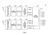
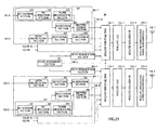
- FIG.2 is a block diagram showing a configuration of base station 10.
- N data symbol generation sections 102-1 to 102-N
- N data symbol generation sections 104-1 to 104-N pilot assignment section 106
- pilot modulation sections 108-1 and 108-2 two multiplexing sections 110-1 and 110-2
- two IFFT inverse fast Fourier transform
- GI guard interval
- Data symbol generation sections 102-1 to 102-N, pilot modulation section 108-1, multiplexing section 110-1, IFFT section 112-1, GI addition section 114-1, and transmission radio processing section 116-1 are provided in association with antenna 118-1, and data symbol generation sections 104-1 to 104-N, pilot modulation section 108-2, multiplexing section 110-2, IFFT section 112-2, GI addition section 114-2 and transmission radio processing section 116-2 are provided in association with antenna 118-2.
- N data symbol generation sections 102-1 to 102-N have the same configuration, and therefore, are referred to as “data symbol generation section 102" in descriptions for arbitrary one of N data symbol generation sections 102-1 to 102-N.
- N data symbol generation sections 104-1 to 104-N have the same configuration, and therefore, are referred to as "data symbol generation section 104" in descriptions for arbitrary one of N data symbol generation sections 104-1 to 104-N.
- Data symbol generation section 102 and data symbol generation section 104 are each provided in association with two adjacent subcarriers out of M subcarriers. For example, data signals transmitted using subcarriers f 1 and f 2 are inputted to data symbol generation section 102-1.
- data signals inputted to data symbol generation section 102-1 include data signal D(1, 1) transmitted from antenna 118-1 using subcarrier f 1 and data signal D(1, 2) transmitted from antenna 118-1 using subcarrier f 2 .
- data signals inputted to data symbol generation section 104-1 include data signal D(2, 1) transmitted from antenna 118-1 using subcarrier f 1 and data signal D(2, 2) transmitted from antenna 118-2 using subcarrier f 2 .
- Data symbol generation section 102 has two data modulation sections 121 and 122, two repetition sections 123 and 124, Q inversion section 125 and IQ inversion section 126.
- Data modulation section 121, repetition section 123 and Q inversion section 125 are provided in association with D (1, 2n-1) transmitted from subcarriers having odd identification numbers, out of D (1, 2n-1) and D (1, 2n) inputted to data symbol generation section 102.
- Data modulation section 122, repetition section 124 and IQ inversion section 126 are provided in association with D(1, 2n) transmitted from subcarriers having even identification numbers, out of D(1, 2n-1) and D(1, 2n) inputted to data symbol generation section 102. Furthermore, n is an arbitrary integer between 1 to N.
- Data modulation section 121 modulates D (1, 2n-1) using quadrature phase shift keying (QPSK) and generates a modulated data symbol.
- the modulated data symbol generated by data modulation section 121 is outputted to repetition section 123.
- Data modulation section 122 modulates D (1, 2n) and generates a modulated data symbol.
- the modulated data symbol generated by data modulation section 122 is outputted to repetition section 124.
- Repetition section 123 duplicates (repeats) the modulated data symbol inputted from data modulation section 121 according to the number of repetitions.
- the number of repetitions is "2.” That is, repetition section 123 outputs the inputted modulated data symbol as is to Q inversion section 125, and following the output of the modulated data symbol, generates a duplicate data symbol having the same value as the modulated data symbol and outputs the duplicate data symbol to Q inversion section 125.
- Repetition section 124 repeats the modulated data symbol inputted from data modulation section 122 according to the number of repetitions. In this embodiment, the number of repetitions is "2.” That is, repetition section 124 outputs the inputted modulated data symbol as is to IQ inversion section 126 and then, following the output of the modulated data symbol, generates a duplicate data symbol having the same value as the modulated data symbol and outputs the duplicate data symbol to IQ inversion section 126.
- Q inversion section 125 as a generation means of a radio transmission apparatus, outputs the modulated data symbol inputted from repetition section 123 as is to multiplexing section 110-1.
- Q inversion section 125 inverts the positive/negative sign of the value of the quadrature (Q) component of the duplicate data symbol inputted after the modulated data symbol from repetition section 123 and generates a Q inverted data symbol.
- the generated Q inverted data symbol is outputted to multiplexing section 110-1 following the output of the modulated data symbol.
- This Q inverted data symbol corresponds to the modulated data symbol generated by data modulation section 121 and becomes a signal having a specific value when combined with the modulated data symbol.
- the average symbol obtained when the Q inverted symbol and modulated data symbol are combined is substantially the same as the binary phase shift keying (BPSK) modulated signal.
- BPSK binary phase shift keying
- IQ inversion section 126 as a generation means of a radio transmission apparatus, outputs the modulated data symbol inputted from repetition section 124 as is to multiplexing section 110-1.
- IQ inversion section 126 inverts the positive/negative sign of the value of the in-phase (I) component and the positive/negative sign of the value of the Q component of the duplicate data symbol inputted after the modulated data symbol from repetition section 124 and generates an IQ inverted data symbol. That is, this IQ inverted data symbol corresponds to the modulated data symbol generated by data modulation section 122 and becomes a signal having a specific value when combined with the modulated data symbol.
- the generated IQ inverted data symbol is outputted to multiplexing section 110-1 following the output of the modulated data symbol.
- the Q inverted symbol and the IQ inverted symbol are generically referred to as "inverted symbol.”
- Data symbol generation section 104 has two data modulation sections 131 and 132, two repetition sections 133 and 134, IQ inversion section 135 and Q inversion section 136.
- Data modulation section 131, repetition section 133 and IQ inversion section 135 are provided in association with D(2, 2n-1) transmitted from subcarriers having odd identification numbers, out of D (2, 2n-1) and D (2, 2n) inputted to data symbol generation section 104.
- data modulation section 132, repetition section 134 and Q inversion section 136 are provided in association with D(2, 2n) transmitted from subcarriers having even identification numbers, out of D (2, 2n-1) and D (2, 2n) inputted to data symbol generation section 104.
- Data modulation section 131 modulates D(2, 2n-1) to generate a modulated data symbol.
- the modulated data symbol generated by data modulation section 131 is outputted to repetition section 133.
- Data modulation section 132 modulates D(2, 2n) using QPSK to generate a modulated data symbol.
- the modulated data symbol generated by data modulation section 132 is outputted to repetition section 134.
- Repetition section 133 repeats the modulated data symbol inputted from data modulation section 131 according to the number of repetitions. In this embodiment, the number of repetitions is "2.” That is, repetition section 133 outputs the inputted modulated data symbol as is to IQ inversion section 135 and then, following the output of the modulated data symbol, generates a duplicate data symbol having the same value as the modulated data symbol and outputs the duplicate data symbol to IQ inversion section 135.
- Repetition section 134 repeats the modulated data symbol inputted from data modulation section 132 according to the number of repetitions. In this embodiment, the number of repetitions is "2.” That is, repetition section 134 outputs the inputted modulated data symbol as is to Q inversion section 136 and then, following the output of the modulated data symbol, generates a duplicate data symbol having the same value as the modulated data symbol and outputs the duplicate data symbol to Q inversion section 136.
- IQ inversion section 135 as a generation means of a radio transmission apparatus, outputs the modulated data symbol inputted from repetition section 133 as is to multiplexing section 110-2.
- IQ inversion section 135 inverts the positive/negative sign of the value of the I component and the positive/negative sign of the value of the Q component of the duplicate data symbol inputted after the modulated data symbol from repetition section 133 and generates an IQ inverted data symbol.
- This IQ inverted data symbol corresponds to the modulated data symbol generated by data modulation section 131 and becomes a signal having a specific value when combined with the modulated data symbol.
- the generated IQ inverted data symbol is outputted to multiplexing section 110-2 following the output of the modulated data symbol.
- Q inversion section 136 as a generation means of a radio transmission apparatus, outputs the modulated data symbol inputted from repetition section 134 as is to multiplexing section 110-2.
- Q inversion section 136 inverts the positive/negative sign of the value of the Q component of the duplicate data symbol inputted after the modulated data symbol from repetition section 134 and generates a Q inverted data symbol.
- This Q inverted data symbol corresponds to the modulated data symbol generated by data modulation section 132 and becomes a signal having a specific value when combined with the modulated data symbol.
- the generated Q modulated data symbol is outputted to multiplexing section 110-2 following the output of the modulated data symbol.
- Pilot assignment section 106 assigns pilot signals to the odd number subcarriers and the even number subcarriers.
- the pilot signals assigned to the odd number subcarriers are outputted to pilot modulation section 108-1, and the pilot signals assigned to the even number subcarriers are outputted to pilot modulation section 108-2.
- pilot assignment section 106 generates a zero signal having a zero value.
- the generated zero signal is outputted to multiplexing sections 110-1 and 110-2.
- the pilot signal and zero signal are known signals.
- Pilot modulation section 108-1 modulates the pilot signals inputted from pilot assignment section 106 and generates a pilot symbol .
- the generated pilot symbol is outputted to multiplexing section 110-1.
- BPSK is used for modulation of the pilot signals.
- Pilot modulation section 108-2 modulates the pilot signals inputted from pilot assignment section 106 and generates a pilot symbol.
- BPSK is used for this modulation.
- the generated pilot symbol is outputted to multiplexing section 110-2.
- the combination of the pilot assignment section 106 and pilot modulation sections 108-1 and 108-2 configures a known signal generation section that generates a known signal.
- Multiplexing section 110-1 multiplexes the modulated data symbol and Q inverted data symbol inputted from Q inversion section 125, the modulated data symbol and IQ inverted data symbol inputted from IQ inversion section 126, the pilot symbol inputted from pilot modulation section 108-1, and the zero signal inputted from pilot assignment section 106 and generates a multiplexed signal to be transmitted from antenna 118-1.
- the format of the multiplexed signal generated by multiplexing section 110-1 will be specifically described later.
- Multiplexing section 110-2 multiplexes the modulated data symbol and IQ inverted data symbol inputted from IQ inversion section 135, the modulated data symbol and Q inverted data symbol inputted from Q inversion section 136, the pilot symbol inputted from pilot modulation section 108-2, and the zero signal inputted from pilot assignment section 106 and generates a multiplexed signal to be transmitted from antenna 118-2.
- the format of the multiplexed signal generated by multiplexing section 110-2 will be specifically described later.
- IFFT section 112-1 as an assignment means, performs IFFT processing on the multiplexed signal generated by multiplexing section 110-1, and thereby assigns the multiplexed signal to subcarriers.
- IFFT section 112-2 as an assignment means, performs IFFT processing on the multiplexed signal generated by multiplexing section 110-2, and thereby assigns the multiplexed signal to subcarriers.
- GI addition section 114-1 adds a GI at a predetermined position of the multiplexed signal subjected to IFFT processing by IFFT section 112-1.
- GI addition section 114-2 adds a GI at a predetermined position of the multiplexed signal subjected to IFFT processing by IFFT section 112-2.
- Transmission radio processing section 116-1 generates a radio signal by performing predetermined transmission radio processing (such as D/A conversion and up-conversion) on the multiplexed signal to which GI is added by GI addition section 114-1, and transmits the generated radio signal from antenna 118-1.
- Transmission radio processing section 116-2 generates a radio signal by performing predetermined transmission radio processing on the multiplexed signal to which GI is added by GI addition section 114-2, and transmits the generated radio signal from antenna 118-2.
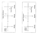
- the format of the multiplexed signal generated at base station 10 having the above-described configuration will be explained.
- the format will be explained for multiplexed signals transmitted using subcarriers f 1 and f 2 during a period between time t1 and time t5.
- a modulated data symbol (QPSK symbol) generated by data modulation section 121 is arranged.
- QPSK symbol a modulated data symbol generated by Q inversion section 125--a Q inverted symbol corresponding to the QPSK symbol arranged at the position of subcarrier f 1 and time t2--is arranged.
- a QPSK symbol generated by data modulation section 121 (that is, a modulated data symbol generated following the QPSK symbol arranged at the position of subcarrier f 1 and time t2) is arranged.
- the subcarrier signal corresponding to subcarrier f 1 is a signal obtained by time division multiplexing a signal having a known value (that is, the pilot symbol generated by pilot modulation section 108-1), the QPSK symbol generated by data modulation section 121 and the Q inverted symbol generated by Q inversion section 125.
- the zero signal is arranged (that is, a pilot symbol is not arranged at this position).
- a QPSK symbol generated by data modulation section 122 is arranged.
- a QPSK symbol generated by data modulation section 122 (that is, a modulated data symbol generated following the QPSK symbol arranged at the position of subcarrier f 2 and time t2) is arranged.
- the subcarrier signal corresponding to subcarrier f 2 is a signal obtained by time division multiplexing a signal having a known value (that is, the zero signal), the QPSK symbol generated by data modulation section 122 and the IQ inverted symbol generated by IQ inversion section 126.
- the zero signal is arranged (that is, a pilot symbol is not arranged at this position).
- a QPSK symbol generated by data modulation section 131 is arranged.
- a QPSK symbol generated by data modulation section 131 (that is, a modulated data symbol generated following the QPSK symbol arranged at the position of subcarrier f 1 and time t2) is arranged.
- the subcarrier signal corresponding to subcarrier f 1 is a signal obtained by time division multiplexing a signal having a known value (that is, the zero signal), the QPSK symbol generated by data modulation section 131 and the IQ inverted symbol generated by IQ inversion section 135.
- a QPSK symbol generated by data modulation section 132 is arranged.
- a QPSK symbol generated by data modulation section 132 (that is, a modulated data symbol generated following the QPSK symbol arranged at the position of subcarrier f 2 and time t2) is arranged.
- the subcarrier signal corresponding to subcarrier f 2 is a signal obtained by time division multiplexing a signal having a known value (that is, the pilot symbol generated by pilot modulation section 108-2), the QPSK symbol generated by data modulation section 132 and the Q inverted symbol generated by Q inversion section 136.
- FIG.5A shows an example of a QPSK symbol.
- FIG.5B shows a Q inverted symbol obtained by inverting the positive/negative sign of the Q component of the QPSK symbol.
- an average symbol as shown in FIG. 5C is obtained.
- This average symbol is substantially the same as the BPSKmodulated signal. That is, the Q inverted symbol generated by Q inversion sections 125 and 136 is a signal of information of "-1" or "1" when combined with the corresponding QPSK symbol through averaging processing.
- FIG.6A shows an example of a QPSK symbol.
- FIG.6B shows an IQ inverted symbol obtained by inverting the positive/negative sign of the I component and the positive/negative sign of the Q component of the QPSK symbol.
- an average symbol as shown in FIG.6C is obtained.
- This average symbol is substantially the same as the zero signal. That is, the IQ inverted symbol generated by IQ inversion sections 126 and 135 is a signal having the specific value "0" when combined with the corresponding QPSK symbol through averaging processing.
- mobile station 20 has two antennas 202-1 and 202-2, two reception radio processing sections 204-1 and 204-2, two GI removal sections 206-1 and 206-2, two fast Fourier transform (FFT) sections 208-1 and 208-2, two subcarrier demultiplexing sections 210-1 and 210-2 and N MIMO reception sections 212-1 to 212-N.
- N MIMO reception sections 212-1 to 212-N have the same configuration, and therefore, are hereinafter referred to as "MIMO reception section 212" in descriptions for arbitrary one of NMIMO reception sections 212-1 to 212-N.
- Reception radio processing section 204-1, GI removal section 206-1, FFT section 208-1, and subcarrier demultiplexing section 210-1 are provided in association with antenna 202-1
- reception radio processing section 204-2, GI removal section 206-2, FFT section 208-2 and subcarrier demultiplexing section 210-2 are provided in association with antenna 202-2.
- Reception radio processing section 204-1 receives via antenna 202-1 a radio signal transmitted from base station 10 and obtains the received signal by performing predetermined reception radio processing (such as down-conversion and A/D conversion) on the radio signal.
- Reception radio processing section 204-2 receives via antenna 202-2 a radio signal transmitted from base station 10 and obtains the received signal by performing predetermined reception radio processing (such as down-conversion and A/D conversion) on the radio signal.
- GI removal section 206-1 removes the GI added in a predetermined position of the received signal obtained by reception radio processing section 204-1.
- GI removal section 206-2 removes the GI added in a predetermined position of the received signal obtained by reception radio processing section 204-2.
- FFT section 208-1 performs FFT processing on the received signal from which the GI is removed by GI removal section 206-1.
- FFT section 208-2 performs FFT processing on the received signal from which the GI is removed by GI removal section 206-2.
- Subcarrier demultiplexing section 210-1 demultiplexes on a per channel estimation unit basis the received signal subjected to FFT processing by FFT section 208-1.
- the combination of two subcarriers f 2n-1 and f 2n is used as a channel estimation unit.
- subcarrier demultiplexing section 210-1 outputs to MIMO reception section 212 received signal RS(2, 2n-1) of subcarrier f 2n-1 and received signal RS(1, 2n) of subcarrier f 2n . More specifically, RS (1, 1) and RS (1, 2) are outputted to MIMO reception section 212-1, and RS(1, 2N-1) and RS(1, 2N) are outputted to MIMO reception section 212-N.
- the received signal of subcarrier f k received by antenna 202-i is expressed as RS (i, k) .
- Subcarrier demultiplexing section 210-2 demultiplexes on a per channel estimation unit basis the received signal subjected to FFT processing by FFT section 208-2.
- the combination of two subcarriers f 2n-1 and f 2n is used as a channel estimation unit.
- subcarrier demultiplexing section 210-2 outputs to MIMO reception section 212 received signal RS(2, 2n-1) of subcarrier f 2n-1 and received signal RS(2, 2n) of subcarrier f 2n . More specifically, RS (2, 1) and RS (2, 2) are outputted to MIMO reception section 212-1, and RS(2, 2N-1) and RS(2, 2N) are outputted to MIMO reception section 212-N.
- MIMO reception section 212 performs MIMO reception processing on RS (1, 2n-1) and RS (1, 2n) inputted from subcarrier demultiplexing section 210-1, and RS (2, 2n-1) and RS(2, 2n) inputted from subcarrier demultiplexing section 210-2, and outputs D(j, 2n-1) and D(j, 2n) transmitted from base station 10.
- MIMO reception section 212 will be described with reference to the block diagram of MIMO reception section 212-1 shown in FIG.8.
- MIMO reception section 212 has two data/pilot demultiplexing sections 221 and 222, two channel estimation sections 223 and 224, two channel estimation value correction sections 225 and 226, two average symbol generation sections 227 and 228, demultiplexing coefficient calculation section 229, two stream demultiplexing sections 230 and 231, two Q inversion sections 232 and 233, two IQ inversion sections 234 and 235, four symbol combination sections 236, 237, 238 and 239, and four data demodulation sections 240, 241, 242 and 243.
- Data/Pilot demultiplexing section 221 as an extraction means, demultiplexes the data symbols and pilot symbols of RS (1, 2n-1) and RS(1, 2n) inputted from subcarrier demultiplexing section 210-1.
- data/pilot demultiplexing section 221 extracts the signal RD(1, 2n-1) of the portion corresponding to the data symbol and the signal of the portion corresponding to the pilot symbol from RS (1, 2n-1), outputs the signal of the portion corresponding to the pilot symbol to channel estimation section 223, and outputs RD (1, 2n-1) to stream demultiplexing section 230 and average symbol generation section 227.
- data/pilot demultiplexing section 221 extracts signal RD(1, 2n) of the portion corresponding to the data symbol and the signal of the portion corresponding to the pilot symbol from RS (1, 2n), outputs the signal of the portion corresponding to the pilot symbol to channel estimation section 223, and outputs RD(1, 2n) to stream demultiplexing section 231 and average symbol generation section 227.
- RD(1, 2n-1) and RD (1, 2n) are comprised of a portion corresponding to a modulated data symbol and a portion corresponding to an inverted symbol generated to become a signal having a specific value when combined with the modulation symbol through averaging processing.
- Channel estimation section 223 performs channel estimation using an input signal from data/pilot demultiplexing section 221, and obtains channel estimation values h(1, 1) and h(2, 1). The obtained channel estimation values h (1, 1) andh(2, 1) are outputted to channel estimation value correction section 225.
- RD(1, 2n-1) and RD(1, 2n) are inputted from data/pilot demultiplexing section 221 to average symbol generation section 227 used as a generation means of the radio reception apparatus.
- Average symbol generation section 227 combines through averaging processing the portion corresponding to the modulated data symbol in RD(1, 2n-1) and the portion arranged at the position immediately after the portion, that is, the portion corresponding to the inverted symbol. As a result, an average symbol is generated.
- average symbol generation section 227 combines through averaging processing the portion corresponding to the modulated data symbol in RD(1, 2n) and the portion arranged at the position immediately after the portion, that is, the portion corresponding to the inverted symbol. As a result, an average symbol is generated. The generated average symbols are outputted to channel estimation value correction section 225.
- Channel estimation value correction section 225 corrects channel estimation values h(1, 1) and h(2, 1) inputted from channel estimation section 223 using the average symbols inputted from average symbol generation section 227.
- the corrected channel estimation values h (1, 1) and h (2, 1) areoutputtedtodemultiplexingcoefficient calculation section 229. That is, the combination of channel estimation section 223 and channel estimation value correction section 226 configure an estimation section used as an estimation means of the radio reception apparatus. A specific example of the operation of the estimation section will be described later.
- Data/Pilot demultiplexing section 222 as an extraction means, demultiplexes the data symbols and pilot symbols of RS (2, 2n-1) and RS (2, 2n) inputted from subcarrier demultiplexing section 210-2.
- data/pilot demultiplexing section 222 extracts signal RD(2, 2n-1) of the portion corresponding to the data symbol and the signal of the portion corresponding to the pilot symbol from RS (2, 2n-1), outputs the signal of the portion corresponding to the pilot symbol to channel estimation section 224, and outputs RD (2, 2n-1) to stream demultiplexing section 230 and average symbol generation section 228.
- data/pilot demultiplexing section 222 extracts signal RD(2, 2n) of the portion corresponding to the data symbol and the signal of the portion corresponding to the pilot symbol from RS (2, 2n), outputs the signal of the portion corresponding to the pilot symbol to channel estimation section 224, and outputs RD(2, 2n) to stream demultiplexing section 231 and average symbol generation section 228.
- RD(2, 2n-1) and RD(2, 2n) is comprised of a portion corresponding to a modulated data symbol and a portion corresponding to an inverted symbol generated to become a signal having a specific value when combined with the modulation symbol through averaging processing.
- Channel estimation section 224 performs channel estimation using an input signal from data/pilot demultiplexing section 222, and obtains channel estimation values h(1, 2) and h(2, 2). The obtained channel estimation values h (1, 2) andh(2, 2) are outputted to channel estimation value correction section 226.
- RD(2, 2n-1) and RD(2, 2n) are inputted from data/pilot demultiplexing section 222 to average symbol generation section 228 used as a generation means of the radio reception apparatus.
- Average symbol generation section 228 combines through averaging processing the portion corresponding to the modulated data symbol in RD(2, 2n-1) and the portion arranged at the position immediately after the portion, that is, the portion corresponding to the inverted symbol. As a result, an average symbol is generated.
- average symbol generation section 228 combines through averaging processing the portion corresponding to the modulated data symbol in RD(2, 2n) and the portion arranged at the position immediately after the portion, that is, the portion corresponding to the inverted symbol. As a result, an average symbol is generated. The generated average symbols are outputted to channel estimation value correction section 226.
- Channel estimation value correction section 226 corrects channel estimation values h(1, 2) and h(2, 2) inputted from channel estimation section 224 using the average symbols inputted from average symbol generation section 228.
- the corrected channel estimation values h (1, 2) andh(2, 2) areoutputtedtodemultiplexingcoefficient calculation section 229. That is, the combination of channel estimation section 224 and channel estimation value correction section 226 configures an estimation section used as an estimation means of the radio reception apparatus, similar to the combination of channel estimation section 223 and channel estimation value correction section 225. A specific example of the operation of the estimation section will be described later.
- Demultiplexing coefficient calculation section 229 calculates demultiplexing coefficients for demultiplexing a plurality of streams transmitted via MIMO channel 30 using channel estimation values h (1, 1), h(1, 2), h(2, 1) and h(2, 2) inputted from channel estimation value correction sections 225 and 226.
- the demultiplexing coefficients are calculated by, for example, obtaining the inverse matrix of channel matrix H obtained from channel estimation values h (1, 1), h (1, 2), h(2, 1) and h(2, 2 ) .
- the calculated demultiplexing coefficients are outputted to stream demultiplexing sections 230 and 231.
- Stream demultiplexing section 230 performs stream demultiplexing on RD(1, 2n-1) inputted from data/pilot demultiplexing section 221 and RD(2, 2n-1) inputted from data/pilot demultiplexing section 222.
- the demultiplexing coefficients inputted from demultiplexing coefficient calculation section 229 are used in this stream demultiplexing processing.
- D (1, 2n-1) and D (2, 2n-1) are obtained through the stream demultiplexing processing of stream demultiplexing section 230.
- D(1, 2n-1) and D(2, 2n-1) are outputted to Q inversion section 232 and IQ inversion section 234, respectively.
- Q inversion section 232 outputs the modulated data symbol in D (1, 2n-1) inputted from stream demultiplexing section 230 as is to symbol combination section 236. Further, Q inversion section 232 inverts the positive/negative sign of the value of the Q component of the Q inverted symbol in D (1, 2n-1) inputted from stream demultiplexing section 230 and restores the duplicate symbol. Then, Q inversion section 232 outputs the restored duplicate symbol to symbol combination section 236 following the output of the modulated data symbol.
- Symbol combination section 236 combines the modulated data symbol inputted from Q inversion section 232 and the duplicate symbol inputted from Q inversion section 232 after the modulated data symbol to obtain a combined data symbol.
- the obtained combined symbol is inputted to data demodulation section 240.
- Data demodulation section 240 demodulates the combined data symbol inputted from symbol combination section 236 and outputs D(1, 2n-1).
- QPSK is used for demodulation of D (1, 2n-1), and therefore data demodulation section 240 uses QPSK for demodulation processing.
- IQ inversion section 234 outputs the modulated data symbol of D(2, 2n-1) inputted from stream demultiplexing section 230 as is to symbol combination section 237. Further, IQ inversion section 234 inverts the positive/negative sign of the I component and the positive/negative sign of the Q component of the IQ inverted symbol in D(2, 2n-1) inputted from stream demultiplexing section 230 and restores the duplicate symbol. Then, IQ inversion section 234 outputs the restored duplicate symbol to symbol combination section 237 following the output of the modulated data symbol.
- Symbol combination section 237 combines the modulated data symbol inputted from IQ inversion section 234 and the duplicate symbol inputted from IQ inversion section 234 after the modulated data symbol to obtain a combined data symbol.
- the obtained combined symbol is inputted to data demodulation section 241.
- Data demodulation section 241 demodulates the combined data symbol inputted from symbol combination section 237 and outputs D(2, 2n-1).
- Stream demultiplexing section 231 performs stream demultiplexing on RD(1, 2n) inputted from data/pilot demultiplexing section 221 and RD(2, 2n) inputted from data/pilot demultiplexing section 222.
- the demultiplexing coefficients inputted from demultiplexing coefficient calculation section 229 are used in this stream demultiplexing processing.
- D(1, 2n) and D(2, 2n) are obtained through the stream demultiplexing processing of stream demultiplexing section 231.
- D (1, 2n) and D(2, 2n) are outputted to IQ inversion section 235 and Q inversion section 233, respectively.
- IQ inversion section 235 outputs the modulated data symbol in D(1, 2n) inputted from stream demultiplexing section 231 as is to symbol combination section 238. Further, IQ inversion section 235 inverts both the positive/negative sign of the value of the I component and the positive/negative sign of the value of the Q component of the IQ inverted symbol in D(1, 2n) inputted from stream demultiplexing section 231 and restores the duplicate symbol. Then, IQ inversion section 235 outputs the restored duplicate symbol to symbol combination section 238 following the output of the modulated data symbol.
- Symbol combination section 238 combines the modulated data symbol inputted from IQ inversion section 235 and the duplicate symbol inputted from IQ inversion section 235 after the modulated data symbol to obtain a combined data symbol.
- the obtained combined symbol is inputted to data demodulation section 242.
- Data demodulation section 242 demodulates the combined data symbol inputted from symbol combination section 238 and outputs D(1, 2n).
- Q inversion section 233 outputs the modulated data symbol in D(2, 2n) inputted from stream demultiplexing section 231 as is to symbol combination section 239. Further, Q inversion section 233 inverts the positive/negative sign of the Q component of the Q inverted symbol in D(2, 2n) inputted from stream demultiplexing section 231 and restores the duplicate symbol. Then, Q inversion section 233 outputs the restored duplicate symbol to symbol combination section 239 following the output of the modulated data symbol.
- Symbol combination section 239 combines the modulated data symbol inputted from Q inversion section 233 and the duplicate symbol inputted from Q inversion section 233 after the modulated data symbol to obtain a combined data symbol.
- the obtained combined symbol is inputted to data demodulation section 243.
- Data demodulation section 243 demodulates the combined data symbol inputted from symbol combination section 239 and outputs D(2, 2n).
- QPSK is used for modulation of D(2, 2n), and therefore data demodulation section 243 uses QPSK for demodulation processing.
- the multiplexed signal shown in FIG.9A is transmitted from antenna 118-1 of base station 10.
- the format of the multiplexed signal of FIG.9A is the same as that shown in FIG.3.
- the numbers in parentheses shown at the arranged positions of the QPSK symbol and Q inverted symbol are the I component values and Q component values of the symbols.
- the multiplexed signal shown in FIG.9B is transmitted from antenna 118-2 of base station 10.
- the format of the multiplexed signal of FIG.9B is the same as that shown in FIG.4.
- the numbers in parentheses shown at the arranged positions of the QPSK symbol and IQ inverted symbol are the I component values and Q component values of the symbols.
- the multiplexed signal of FIG.9A and the multiplexed signal of FIG.9B are affected by characteristics C(1, 1), C(2, 1), C(1, 2) and C(2, 2) of MIMO channel 30, and arrive at mobile station 20.
- Characteristics C(1, 1), C(2, 1), C(1, 2) and C(2, 2) for each timing of MIMO channel 30 are shown in FIG.9C.
- a radio signal in which the multiplexed signal of FIG.9A and the multiplexed signal of FIG.9B affected by characteristics C(1, 1) and C(2, 1) of MIMO channel 30 are present arrives at antenna 202-1 of mobile station 20.
- the received signal of antenna 202-1 is shown in FIG.9D.
- the numbers in parentheses shown at the arranged positions of the symbols of the received signal of FIG.9D are the I component value and Q component value of the symbols.
- a radio signal in which the multiplexed signal of FIG.9A and the multiplexed signal of FIG.9B affected by characteristics C (1, 2) and C(2, 2) of MIMO channel 30 are present arrives at antenna 202-2 of mobile station 20.
- the received signal of antenna 202-2 is shown in FIG.9E.
- the numbers in parentheses shown at the arranged positions of the symbols of the received signal of FIG.9E are the I component value and Q component value of the symbols.
- channel estimation section 223 performs channel estimation using the pilot symbol arranged in the portion of time t1 of the received signal of FIG.9D, and obtains channel estimation values h(1, 1) and h(2, 1).
- average symbol generation section 227 combines the modulated data symbol of time t2 and the Q inverted symbol of time t3 to generate an average symbol for the subcarrier signal corresponding to subcarrier f 1 in the received signal of FIG. 9D. Furthermore, average symbol generation section 227 combines the modulated data symbol of time t4 and the Q inverted symbol of time t5 to generate an average symbol for the subcarrier signal corresponding to subcarrier f 1 in the received signal of FIG.9D. Furthermore, average symbol generation section 227 combines the modulated data symbol of time t2 and the IQ inverted symbol of time t3 to generate an average symbol for the subcarrier signal corresponding to subcarrier f 2 in the received signal of FIG.9D. Furthermore, average symbol generation section 227 combines the modulated data symbol of time t4 and the IQ inverted symbol of time t5 to generate an average symbol for the subcarrier signal corresponding to subcarrier f 2 in the received signal of FIG.9D.
- channel estimation values h (1, 1) and h (2, 1) and the average symbols generated by average symbol generation section 227 are inputted to channel estimation value correction section 225.
- Channel estimation value correction section 225 regards the average symbols inputted from average symbol generation section 227 as BPSK modulated pilot symbols and performs channel estimation using the average symbols.
- the average symbols are regarded as BPSK modulated pilot symbols, and therefore there are two possibilities in channel estimation results depending on whether the BPSK symbol is (-1, 0) or (1, 0).
- Channel estimation value correction section 225 lines up channel estimation value candidates based on the possibilities. For example, for the average symbol of subcarrier f 1 and times t2 to t3, (1, 0.3) and (-1, -0.3) are lined up as channel estimation value candidates. The channel estimation value candidates lined up for each average symbol are shown in FIG.9H.
- channel estimation value correction section 225 compares each candidate with the channel estimation value (the channel estimation value of time t1 in this illustration) obtained from the pilot symbol and selects the candidate having the value closest to the channel estimation value obtained from the pilot symbol (in other words, the value having a smaller square error with respect to the channel estimation value obtained from the pilot symbol).
- the above-described candidates (1, 0.3) and (-1, -0.3) correspond to subcarrier f 1 and therefore are compared with the channel estimation value (1, 0.3) corresponding to subcarrier f 1 .
- candidate (1, 0.3) has a value having a smaller square error with respect to channel estimation value (1, 0.3) compared to (-1, -0.3), and therefore (1, 0.3) is selected.
- the selected candidate (1, 0.3) is determined as the channel estimation value h(1, 1) corresponding to times t2 to t3.
- the candidates encircled in FIG.9H are the candidates selected as a result of the comparison.
- the determined channel estimation value is used for calculating the demultiplexing coefficients at demultiplexing coefficient calculation section 229.
- channel estimation section 224 average symbol generation section 228 and channel estimation value correction section 226.
- channel estimation section 224 performs channel estimation using the pilot symbol arranged in the portion of time t1 of the received signal of FIG.9E, and obtains channel estimation values h(1, 2) and h(2, 2) .
- average symbol generation section 228 combines the modulated data symbol of time t2 and the IQ inverted symbol of time t3 and generates an average symbol for the subcarrier signal corresponding to subcarrier f 1 in the received signal of FIG.9E. Furthermore, average symbol generation section 228 combines the modulated data symbol of time t4 and the IQ inverted symbol of time t5 to generate an average symbol for the subcarrier signal corresponding to subcarrier f 1 in the received signal of FIG. 9E. Furthermore, average symbol generation section 228 combines the modulated data symbol of time t2 and the Q inverted symbol of time t3 to generate an average symbol for the subcarrier signal corresponding to subcarrier f 2 in the received signal of FIG.9E. Furthermore, average symbol generation section 228 combines the modulated data symbol of time t4 and the Q inverted symbol of time t5 to generate an average symbol for the subcarrier signal corresponding to subcarrier f 2 in the received signal of FIG.9E.
- channel estimation values h (1, 2) and h(2, 2) obtained by channel estimation section 224 and the average symbols generated by average symbol generation section 228 are inputted to channel estimation value correction section 226.
- Channel estimation value correction section 226 regards the average symbols inputted from average symbol generation section 228 as BPSK modulated pilot symbols and performs channel estimation using the average symbols.
- the average symbols are regarded as BPSK modulated pilot symbols, and therefore there are two possibilities in the channel estimation results depending on whether the BPSK symbol is (-1, 0) or (1, 0) .
- Channel estimation value correction section 226 lines up channel estimation value candidates based on the possibilities. For example, for the average symbol of times t2 to t3 of subcarrier f 1 , (0.5, 1) and (-0.5, -1) are lined up as channel estimation value candidates. The channel estimation value candidates lined up for each average symbol are shown in FIG.91.
- channel estimation value correction section 226 compares each candidate with the channel estimation value (the channel estimation value of time t1 in this illustration) obtained from the pilot symbol and selects the candidate having the value closest to the channel estimation value obtained from the pilot symbol.
- the candidates (0.5, 1) and (-0.5, -1) corresponding to times t2 to t3 of subcarrier f 1 are compared with channel estimation value (0.5, 1) corresponding to subcarrier f 1 .
- candidate (0.5, 1) has a value closer to the channel estimation value (0.5, 1) compared to (-0.5, -1), and therefore (0.5, 1) is selected.
- the selected candidate (0.5, 1) is determined as channel estimation value h (1, 2) corresponding to times t2 to t3.
- the candidates encircled in FIG. 91 are the candidates selected as a result of the comparison.
- the determined channel estimation value is used for calculating demultiplexing coefficients at demultiplexing coefficient calculation section 229.
- channel estimation using the average symbol obtained from a modulated data symbol and an inverted symbol corresponding to that symbol can be performed in mobile station 20, that is, pilot symbols as well as data symbols can be used for channel estimation.
- pilot symbols as well as data symbols
- a repeated symbol is arranged by time division, but may be arranged in the frequency direction if within a coherent band.
- the subcarrier for mapping the Q inverted symbol used for channel estimation value correction and the subcarrier for mapping the IQ inverted symbol not used for channel estimation value correction are made adjacent, non-adjacent subcarriers may also be used if within a coherent band.
- Embodiment 1 the case has been described as an example where QPSK is applied as the modulation scheme.
- the 16QAM is applied, as shown in FIG.10, the average symbols of the modulated data symbols and Q inverted data symbols becomes four values on the I axis, and, out of the signal points of the four values, the signal points of the two values having smaller absolute values have low SNR, and therefore channel estimation accuracy deteriorates.
- Embodiment 2 of the present invention a case will be described where 16QAM is applied as the modulation scheme.
- FIG.11 is a block diagram showing a configuration of base station 40 according to Embodiment 2 of the present invention.
- the differences between FIG.11 and FIG.2 is that data modulation section 121 is changed to data modulation section 321, data modulation section 122 is changed to data modulation section 322, data modulation section 131 is changed to data modulation section 331, data modulation section 132 is changed to data modulation section 332, Q inversion section 125 is changed to mapping change section 325, and Q inversion section 136 is changed to mapping change section 336.
- Data modulation section 321 modulates D (1, 2n-1) using 16QAM and generates a modulated data symbol.
- the modulated data symbol generated by data modulation section 321 is outputted to repetition section 123.
- Data modulation section 322 modulates D(1, 2n) and generates a modulated data symbol.
- the modulated data symbol generated by data modulation section 322 is outputted to repetition section 124.
- Mapping change section 325 as a generation means of the radio transmission apparatus, outputs the modulated data symbol inputted from repetition section 123 as is to multiplexing section 110-1.
- Mapping change section 325 changes the mapping of the duplicate data symbol inputted after the modulated data symbol from repetition section 123 and generates a mapping change symbol.
- the generated mapping change symbol is outputted to multiplexing section 110-1 following the output of the modulated data symbol.
- This mapping change symbol corresponds to the modulated data symbol generated by data modulation section 321, and the average symbol obtained when the mapping change symbol is combined with this modulated data symbol is substantially the same as the BPSK modulated signal.
- Data modulation section 331 modulates D (2, 2n-1) to generate a modulated data symbol.
- the modulated data symbol generated by data modulation section 331 is outputted to repetition section 133.
- Data modulation section 332 modulates D(2, 2n) using 16QAM and generates a modulated data symbol.
- the modulated data symbol generated by data modulation section 332 is outputted to repetition section 134.
- Mapping change section 336 as a generation means of the radio transmission apparatus, outputs the modulated data symbol inputted from repetition section 134 as is to multiplexing section 110-2.
- Mapping change section 336 changes the mapping of the duplicate data symbol inputted after the modulated data symbol from repetition section 134 and generates a mapping change symbol.
- the generated mapping change symbol is outputted to multiplexing section 110-2 following the output of the modulated data symbol.
- This mapping change symbol corresponds to the modulated data symbol generated by data modulation section 332, and the average symbol obtained when the mapping change symbol is combined with this modulated data symbol is substantially the same as the BPSK modulated signal.
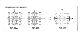
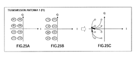
- FIG.12A shows the arrangement pattern of the modulated data symbols generated by data modulation sections 321 and 332.
- the I component of each of the signal points takes two values
- mapping change sections 325 and 336 change the mapping by moving signal points symmetrically using the point on the I axis that indicates the average of these two values as the point of symmetry.
- mapping change sections 325 and 336 change the mapping by moving signal points symmetrically in the I component of the signal points using the point that indicates the average value obtained from the two values as the point of symmetry.
- the mapping change symbol arrangement pattern becomes that shown in FIG.12B.
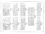
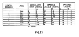
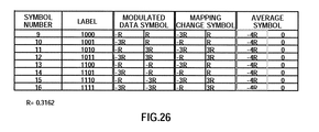
- FIG.13 summarizes the I components and Q components of the modulated data symbols, mapping change symbols and average symbols thereof. Furthermore, R in the figure indicates 0.3162. In this figure, it is clear that the average symbols are all 0 for the Q component, and the two values 4R and -4R for the I component.
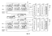
- FIG.14 is a block diagram showing an internal configuration of MIMO reception section 212 according to Embodiment 2 of the present invention.
- the differences between FIG.14 and FIG.8 is that average symbol generation section 227 is changed to average symbol generation section 427, average symbol generation section 228 is changed to average symbol generation section 428, Q inversion section 232 is changed to mapping change section 432, and Q inversion section 233 is changed to mapping change section 433.
- Average symbol generation section 427 combines through averaging processing the portion corresponding to the modulated data symbol in RD (1, 2n-1 ) and the portion arranged at the position immediately after the portion, that is, the portion corresponding to the mapping change symbol. As a result, an average symbol is generated.
- average symbol generation section 427 combines through averaging processing the portion corresponding to the modulated data symbol in RD(1, 2n) and the portion arranged at the position immediately af ter the portion, that is, the portion corresponding to the mapping change symbol. As a result, an average symbol is generated. The generated average symbols are outputted to channel estimation value correction section 225.
- Average symbol generation section 428 combines through averaging processing the portion corresponding to the modulated data symbol in RD (2, 2n-1) and the portion arranged at the position immediately after the portion, that is, the portion corresponding to the mapping change symbol. As a result, an average symbol is generated.
- average symbol generation section 428 combines through averaging processing the portion corresponding to the modulated data symbol in RD(2, 2n) and the portion arranged at the position immediately after the portion, that is, the portion corresponding to the mapping change symbol. As a result, an average symbol is generated. The generated average symbols are outputted to channel estimation value correction section 226.
- Mapping change section 432 outputs the modulated data symbol in D(1, 2n-1) inputted from stream demultiplexing section 230 as is to symbol combination section 236. Further, mapping change section 432 changes the mapping of the mapping change symbol in D(1, 2n-1) inputted from stream demultiplexing section 230 in the same way as mapping change section 325 of FIG.11 and restores the duplicate symbol. Then, mapping change section 432 outputs the restored duplicate symbol to symbol combination section 236 following the output of the modulated data symbol.
- Mapping change section 433 outputs the modulated data symbol in D(2, 2n) inputted from stream demultiplexing section 231 as is to symbol combination section 239. Further, mapping change section 433 changes the mapping of the mapping change symbol in D(2, 2n) inputted from stream demultiplexing section 231 in the same way as mapping change section 336 of FIG.11, and restores the duplicate symbol. Then, mapping change section 433 outputs the restored duplicate symbol to symbol combination section 239 following the output of the modulated data symbol.
- Embodiment 2 in a 16QAM symbol arrangement pattern, by changing the mapping by symmetrically moving the signal points of the right quadrants and left quadrants centering around the Q axis of the IQ plane using the point that indicates the average value of the I component of two values of each of the signal points as the point of symmetry, two values for the average symbols can be obtained from the modulated data symbols and corresponding mapping change symbols even with the modulation scheme is 16QAM, and it is thereby possible to improve channel estimation accuracy and reception error rate characteristics by making the mobile station perform channel estimation using the average symbols.
- Embodiment 2 the case has been described where 16QAM is applied as the modulation scheme, but in Embodiment 3 of the present invention, a case will be described where 64QAM is applied as the modulation scheme.
- the configuration of the base station according to Embodiment 3 of the present invention is the same as the configuration shown in FIG.11 of Embodiment 2, and therefore FIG.11 will be employed, and the configuration of the mobile station according to Embodiment 3 of the present invention is the same as the configuration shown in FIG.7 of Embodiment 1, and therefore FIG.7 will be employed, and duplicate descriptions thereof will be omitted.
- datamodulation section 321 modulates D(1, 2n-1) using 64QAM to generate a modulated data symbol.
- the modulated data symbol generated by data modulation section 321 is outputted to repetition section 123.
- Data modulation section 322 modulates D (1, 2n) to generate a modulated data symbol.
- the modulated data symbol generated by data modulation section 322 is outputted to repetition section 124.
- Mapping change section 325 as a generation means of the radio transmission apparatus, outputs the modulated data symbol inputted from repetition section 123 as is to multiplexing section 110-1.
- Mapping change section 325 changes the mapping of the duplicate data symbol inputted after the modulated data symbol from repetition section 123 and generates a mapping change symbol.
- the generated mapping change symbol is outputted to multiplexing section 110-1 following the output of the modulated data symbol.
- This mapping change symbol corresponds to the modulated data symbol generated by data modulation section 321, and the average symbol obtained when the mapping change symbol is combined with this modulated data symbol is substantially the same as the BPSK modulated signal.
- Data modulation section 331 modulates D(2, 2n-1) to generate a modulated data symbol.
- the modulated data symbol generated by data modulation section 331 is outputted to repetition section 133.
- Data modulation section 332 modulates D(2, 2n) using 64QAM to generate a modulated data symbol.
- the modulated data symbol generated by data modulation section 332 is outputted to repetition section 134.
- Mapping change section 336 as a generation means of the radio transmission apparatus, outputs the modulated data symbol inputted from repetition section 134 as is to multiplexing section 110-2.
- Mapping change section 336 changes the mapping of the duplicate data symbol inputted after the modulated data symbol from repetition section 134 and generates a mapping change symbol.
- the generated mapping change symbol is outputted to multiplexing section 110-2 following the output of the modulated data symbol.
- This mapping change symbol corresponds to the modulated data symbol generated by data modulation section 332 and the average symbol obtained when the mapping change symbol is combined with this modulated data symbol is substantially the same as the BPSK modulated signal.
- FIG.15A shows the arrangement pattern of the modulated data symbols generated by data modulation sections 321 and 332.
- the I component of each of the signal points takes four values
- mapping change sections 325 and 336 change the mapping by moving signal points symmetrically using the point on the I axis that indicates the average of these four values as the point of symmetry.
- mapping change sections 325 and 336 change the mapping by moving signal points symmetrically in the I component of each of the signal points using the point that indicates the average value obtained from the four values as the point of symmetry.
- the mapping change symbol arrangement pattern becomes that shown in FIG.15B.
- FIG.16 summarizes the I components and Q components of the modulated data symbols, mapping change symbols and average symbols thereof. Furthermore, R in the figure indicates 0.154. In this figure, it is clear that the average symbols are all 0 for the Q component, and the two values 8R and -8R for the I component.
- Embodiment 3 in a 64QAM symbol arrangement pattern, by changing the mapping by symmetrically moving the signal points of the right quadrants and left quadrants centering around the Q axis of the IQ plane using the point that indicates the average value of the I component of four values of each of the signal points as the point of symmetry, two values for the average symbols can be obtained from the modulated data symbols and corresponding mapping change symbols even with the 64QAM modulation scheme, and it is thereby possible to improve channel estimation accuracy and reception error rate characteristics by making the mobile station perform channel estimation using the average symbols.
- Embodiments 1 to 3 the case has been described where QPSK, 16QAM and 64QAM are applied as modulation schemes, but, in this embodiment, a case will be described where 8 PSK is applied as the modulation scheme.
- the configuration of the base station according to Embodiment 4 of the present invention is the same as the configuration shown in FIG.11 of Embodiment 2, and therefore FIG.11 will be employed, and the configuration of the mobile station according to Embodiment 4 of the present invention is the same as the configuration shown in FIG.7 of Embodiment 1, and therefore FIG.7 will be employed, and duplicate descriptions thereof will be omitted.
- datamodulationsection 321 modulates D(1, 2n-1) using 8PSK to generate a modulated data symbol.
- the modulated data symbol generated by data modulation section 321 is outputted to repetition section 123.
- Data modulation section 322 modulates D(1, 2n) to generate a modulated data symbol.
- the modulated data symbol generated by data modulation section 322 is outputted to repetition section 124.
- Mapping change section 325 as a generation means of the radio transmission apparatus, outputs the modulated data symbol inputted from repetition section 123 as is to multiplexing section 110-1.
- Mapping change section 325 changes the mapping of the duplicate data symbol inputted after the modulated data symbol from repetition section 123 and generates a mapping change symbol.
- the generatedmapping change symbol is outputted to multiplexing section 110-1 following the output of the modulated data symbol.
- This mapping change symbol corresponds to the modulated data symbol generated by data modulation section 321, and the average symbol obtained when the mapping change symbol is combined with this modulated data symbol is substantially the same as the BPSK modulated signal.
- Data modulation section 331 modulates D(2, 2n-1) to generate a modulated data symbol.
- the modulated data symbol generated by data modulation section 331 is outputted to repetition section 133.
- Data modulation section 332 modulates D(2, 2n) using 8PSK to generate a modulated data symbol.
- the modulated data symbol generated by data modulation section 332 is outputted to repetition section 134.
- Mapping change section 336 as a generation means of the radio transmission apparatus, outputs the modulated data symbol inputted from repetition section 134 as is to multiplexing section 110-2.
- Mapping change section 336 changes the mapping of the duplicate data symbol inputted after the modulated data symbol from repetition section 134 and generates a mapping change symbol.
- the generated mapping change symbol is outputted to multiplexing section 110-2 following the output of the modulated data symbol.
- This mapping change symbol corresponds to the modulated data symbol generated by data modulation section 332, and the average symbol obtained when the mapping change symbol is combined with this modulated data symbol is substantially the same as the BPSK modulated signal.
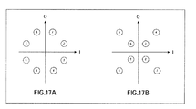
- FIG.17A shows the arrangement pattern of the modulated data symbols generated by data modulation sections 321 and 332.
- the I component of each of the signal points takes two values
- mapping change sections 325 and 336 change the mapping by moving signal points symmetrically using the point on the I axis that indicates the average of these two values as the point of symmetry.
- mapping change sections 325 and 336 change the mapping by moving signal points symmetrically in the I component of each of the signal points using the point that indicates the average value obtained from the two values as the point of symmetry.
- the mapping change symbol arrangement pattern becomes that shown in FIG.17B.
- the 8PSK symbols of FIG.17A and the mapping change symbols of FIG.17B are combined through averaging processing, average symbols of two values are obtained on the I axis. These average symbols are substantially the same as the BPSK modulated signal. That is, the average symbol combined by performing averaging processing on the mapping change symbol generated by mapping change section 325 and 336 and the corresponding 8PSK symbol is a signal of information of "-1" or "1.”
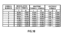
- FIG.18 summarizes the I components and Q components of the modulated data symbols, mapping change symbols and average symbols thereof.
- the average symbols are all 0 for the Q component, and the two values 1.307 and -1.307 for the I component.
- Embodiment 4 in an 8PSK symbol arrangement pattern, by changing the mapping by symmetrically moving the signal points of the right quadrants and left quadrants centering around the Q axis of the IQ plane using the point that indicates the average value of the I component of two values of each of the signal points as the point of symmetry, two values for the average symbols can be obtained from the modulated data symbols and corresponding mapping change symbols even with the 8PSK modulation scheme, and it is thereby possible to improve channel estimation accuracy and reception error rate characteristics by making the mobile station perform channel estimation using the average symbols.
- Embodiment 4 the case has been described where 8PSK is applied as the modulation scheme, but, in Embodiment 5 of the present invention, a case will be described where 16PSK is applied as the modulation scheme.
- the configuration of the base station according to Embodiment 5 of the present invention is the same as the configuration shown in FIG.11 of Embodiment 2, and therefore FIG.11 will be employed, and the configuration of the mobile station according to Embodiment 5 of the present invention is the same as the configuration shown in FIG.7 of Embodiment 1, and therefore FIG.7 will be employed, and duplicate descriptions thereof will be omitted.
- datamodulation section 321 modulates D(1, 2n-1) using 16PSK to generate a modulated data symbol.
- the modulated data symbol generated by data modulation section 321 is outputted to repetition section 123.
- Data modulation section 322 modulates D(1, 2n) to generate a modulated data symbol.
- the modulated data symbol generated by data modulation section 322 is outputted to repetition section 124.
- Mapping change section 325 as a generation means of the radio transmission apparatus, outputs the modulated data symbol inputted from repetition section 123 as is to multiplexing section 110-1.
- Mapping change section 325 changes the mapping of the duplicate data symbol inputted after the modulated data symbol from repetition section 123 and generates a mapping change symbol.
- the generated mapping change symbol is outputted to multiplexing section 110-1 following the output of the modulated data symbol.
- This mapping change symbol corresponds to the modulated data symbol generated by data modulation section 321, and the average symbol obtained when the mapping change symbol is combined with this modulated data symbol is substantially the same as the four-value AM modulated signal.
- Data modulation section 331 modulates D (2, 2n-1) to generate a modulated data symbol.
- the modulated data symbol generated by data modulation section 331 is outputted to repetition section 133.
- Data modulation section 332 modulates D(2, 2n) using 16PSK to generate a modulated data symbol.
- the modulated data symbol generated by data modulation section 332 is outputted to repetition section 134.
- Mapping change section 336 as a generation means of the radio transmission apparatus, outputs the modulated data symbol inputted from repetition section 134 as is to multiplexing section 110-2.
- Mapping change section 336 changes the mapping of the duplicate data symbol inputted after the modulated data symbol from repetition section 134 and generates a mapping change symbol.
- the generated mapping change symbol is outputted to multiplexing section 110-2 following the output of the modulated data symbol.
- This mapping change symbol corresponds to the modulated data symbol generated by data modulation section 332, and the average symbol obtained when the mapping change symbol is combined with this modulated data symbol is substantially the same as the four-value AM modulated signal.
- FIG.19A shows the arrangement pattern of the modulated data symbols generated by data modulation sections 321 and 332.
- the I component of each of the signal points takes four values
- mapping change sections 325 and 336 change the mapping by moving signal points symmetrically using the point on the I axis that indicates the average of these four values as the point of symmetry.
- mapping change sections 325 and 336 change the mapping by moving signal points symmetrically in the I component of each of the signal points using the point that indicates the average value obtained from the two values as the point of symmetry.
- the mapping change symbol arrangement pattern becomes that shown in FIG.19B.
- FIG.20 summarizes the I components and Q components of the modulated data symbols, mapping change symbols and average symbols thereof.
- the average symbols are all 0 for the Q component, and the four values 1.176, 1.387, -1.176, and -1.387 for the I component.
- Embodiment 5 in a 16PSK symbol arrangement pattern, by changing the mapping by symmetrically moving the signal points of the right quadrants and left quadrants centering around the Q axis of the IQ plane using the point that indicates the average value of the I component of four values of each of the signal points as the point of symmetry, four values for the average symbols can be obtained from the modulated data symbols and the corresponding mapping change symbols even with the 16PSK modulation scheme, and it is thereby possible to improve channel estimation accuracy and reception error rate characteristics by making the mobile station perform channel estimation using the average symbols.
- Embodiment 2 the case has been described where 16QAM is applied as the modulation scheme and channel estimation is performed using average symbols of two values obtained by combining modulated data symbols and mapping change symbols, but, in Embodiment 6 of the present invention, a case will be described where channel estimation is performed using average symbols of one value.
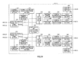
- FIG.21 is a block diagram showing a configuration of the base station according to Embodiment 6 of the present invention.
- bit division section 531, bit insertion section 532 and 16QAM modulation section 533 are added to data modulation section 321 to be data modulation section 521
- bit division section 541, bit insertion section 542 and 16QAM modulation section 543 are added to data modulation section 322 to be data modulation section 522.
- bit division section 531 divides inputted D (1, 2n-1) per three bits, and outputs the signal sequences divided into three bits to bit insertion section 532.
- Bit insertion section 532 inserts 0 at the head of each signal sequence divided into three bits and outputted from bit division section 531, and outputs each signal sequence of four bits with 0 at the head to 16QAM modulation section 533.
- 16QAM modulation section 533 modulates using 16QAM each signal sequence of four bits outputted from bit insertion section 532 and generates a modulated data symbol.
- the modulated data symbol generated by 16QAM modulation section 533 is outputted to repetition section 123.
- Mapping change section 325 as a generation means of the radio transmission apparatus, outputs the modulated data symbol inputted from repetition section 123 as is to multiplexing section 110-1.
- Mapping change section 325 changes the mapping of the duplicate data symbol inputted after the modulated data symbol from repetition section 123 and generates a mapping change symbol.
- the generated mapping change symbol is outputted to multiplexing section 110-1 following the output of the modulated data symbol.
- This mapping change symbol corresponds to the modulated data symbol generated by data modulation section 321.
- Bit division section 541 divides inputted D(2, 2n) per three bits, and outputs the signal sequences divided into three bits to bit insertion section 542.
- Bit insertion section 542 inserts 0 at the head of each signal sequence divided into three bits and outputted from bit division section 541, and outputs each signal sequence of four bits with 0 at the head to 16QAM modulation section 543.
- 16QAM modulation section 543 modulates using 16QAM each signal sequence of four bits outputted from bit insertion section 542 to generate a modulated data symbol.
- the modulated data symbol generated by 16QAM modulation section 543 is outputted to repetition section 134.
- Mapping change section 336 as a generation means of the radio transmission apparatus, outputs the modulated data symbol inputted from repetition section 134 as is to multiplexing section 110-2.
- Mapping change section 336 changes the mapping of the duplicate data symbol inputted after the modulated data symbol from repetition section 134 and generates a mapping change symbol.
- the generated mapping change symbol is outputted to multiplexing section 110-2 following the output of the modulated data symbol. This mapping change symbol corresponds to the modulated data symbol generated by data modulation section 332.
- FIG. 22A shows the arrangement pattern of the modulated data symbols generated by data modulation sections 321 and 332.
- the I component of each of the signal points takes two values, and mapping change sections 325 and 336 change the mapping by moving signal points symmetrically using the point on the I axis that indicates the average of these two values as the point of symmetry.
- the mapping change symbol arrangement pattern becomes that shown in FIG. 22B.
- FIG.23 summarizes the I components and Q components of the modulated data symbols, mapping change symbols and average symbols thereof. Furthermore, R in the figure indicates 0.3162. In this figure, it is clear that the average symbols are all 0 for the Q component, and the single value 4R for the I component.
- FIG.24 is a block diagram showing a configuration of MIMO reception section 212-1 according to Embodiment 6 of the present invention. The difference between FIG.24 and FIG.14 are that head bit removal sections 602 and 604 are added.
- Head bit removal section 602 removes the head bit 0 of each signal sequence of four bits superimposed on each symbol, out of signal sequences outputted from data demodulation section 240 and then outputs the signal sequence of three bits fromwhich the headbit 0 is removed.
- head bit removal section 604 outputs the signal sequences outputted from data demodulation section 243 with the head bits removed.
- Embodiment 6 in a 16QAM symbol arrangement pattern having signal sequences with 0 at the head, by changing the mapping by symmetrically moving the signal points using the point that indicates the average value of the I component of two values of each of the signal points as the point of symmetry, one value for the average symbols can be obtained from the modulated data symbols and the corresponding mapping change symbols, and it is thereby possible to improve channel estimation accuracy and reception error rate characteristics by making the mobile station perform channel estimation using the average symbols.
- FIG.25 shows the correspondence relationship between the 16QAM symbol and mapping change symbol at this time
- FIG.26 shows the I components and Q components of the modulated data symbols, mapping change symbols and average symbols thereof.
- each function block employed in the description of each of the aforementioned embodiments may typically be implemented as an LSI constituted by an integrated circuit. These may be individual chips or partially or totally contained on a single chip.
- each function block is described as an LSI, but this may also be referred to as "IC”, “system LSI”, “super LSI”, “ultra LSI” depending on differing extents of integration.
- circuit integration is not limited to LSI's, and implementation using dedicated circuitry or general purpose processors is also possible.
- FPGA Field Programmable Gate Array
- reconfigurable processor where connections and settings of circuit cells within an LSI can be reconfigured is also possible.
- the radio transmission apparatus, radio reception apparatus, radio transmission method and radio reception method of the present invention can be applied to apparatuses such as a base station apparatus and a mobile station apparatus in a radio communication network system where a plurality of streams are transmitted in parallel.
Landscapes
- Engineering & Computer Science (AREA)
- Computer Networks & Wireless Communication (AREA)
- Signal Processing (AREA)
- Radio Transmission System (AREA)
- Dc Digital Transmission (AREA)
Applications Claiming Priority (3)
| Application Number | Priority Date | Filing Date | Title |
|---|---|---|---|
| JP2004376162 | 2004-12-27 | ||
| JP2005263014 | 2005-09-09 | ||
| PCT/JP2005/023800 WO2006070750A1 (ja) | 2004-12-27 | 2005-12-26 | 無線送信装置、無線受信装置、無線送信方法および無線受信方法 |
Publications (1)
| Publication Number | Publication Date |
|---|---|
| EP1819085A1 true EP1819085A1 (de) | 2007-08-15 |
Family
ID=36614867
Family Applications (1)
| Application Number | Title | Priority Date | Filing Date |
|---|---|---|---|
| EP05820405A Withdrawn EP1819085A1 (de) | 2004-12-27 | 2005-12-26 | Vorrichtung und verfahren zum radiosenden und radioempfang |
Country Status (5)
| Country | Link |
|---|---|
| US (1) | US7764712B2 (de) |
| EP (1) | EP1819085A1 (de) |
| JP (1) | JP4903058B2 (de) |
| BR (1) | BRPI0519470A2 (de) |
| WO (1) | WO2006070750A1 (de) |
Families Citing this family (8)
| Publication number | Priority date | Publication date | Assignee | Title |
|---|---|---|---|---|
| EP1819085A1 (de) * | 2004-12-27 | 2007-08-15 | Matsushita Electric Industrial Co., Ltd. | Vorrichtung und verfahren zum radiosenden und radioempfang |
| US7729443B2 (en) * | 2004-12-28 | 2010-06-01 | Panasonic Corporation | Wireless communication apparatus and wireless communication method |
| JP4655232B2 (ja) * | 2007-04-27 | 2011-03-23 | ソニー株式会社 | 復調装置および方法 |
| KR101387534B1 (ko) | 2008-01-03 | 2014-04-21 | 엘지전자 주식회사 | 반복 채널 코딩을 위한 심볼 매핑 방법 |
| JP5425121B2 (ja) * | 2011-02-17 | 2014-02-26 | 日本電信電話株式会社 | 無線通信方法、及び無線通信システム |
| EP3119051B1 (de) * | 2014-03-13 | 2019-11-20 | Mitsubishi Electric Corporation | Wahrscheinlichkeitserzeugungsvorrichtung und verfahren dafür |
| KR102385494B1 (ko) * | 2016-04-27 | 2022-04-11 | 파나소닉 인텔렉츄얼 프로퍼티 코포레이션 오브 아메리카 | 수신 장치, 수신 방법 및 집적 회로 |
| EP4529109A1 (de) * | 2023-09-22 | 2025-03-26 | Iberdrola QSTP LLC | Verfahren zur datenübertragung in index-modulation ofdm-basierten kommunikationssystemen |
Family Cites Families (13)
| Publication number | Priority date | Publication date | Assignee | Title |
|---|---|---|---|---|
| US5717713A (en) * | 1994-11-18 | 1998-02-10 | Stanford Telecommunications, Inc. | Technique to permit rapid acquisition and alert channel signalling for base station-to-user link of an orthogonal CDMA (OCDMA) communication system |
| US6643338B1 (en) * | 1998-10-07 | 2003-11-04 | Texas Instruments Incorporated | Space time block coded transmit antenna diversity for WCDMA |
| US7068628B2 (en) | 2000-05-22 | 2006-06-27 | At&T Corp. | MIMO OFDM system |
| US6961388B2 (en) * | 2001-02-01 | 2005-11-01 | Qualcomm, Incorporated | Coding scheme for a wireless communication system |
| WO2002067491A1 (en) | 2001-02-21 | 2002-08-29 | Matsushita Electric Industrial Co., Ltd. | Hybrid arq method with single constellation rearrangement |
| KR100474682B1 (ko) | 2001-10-31 | 2005-03-08 | 삼성전자주식회사 | 무선통신시스템에서 패킷 재전송을 위한 송수신 장치 및 방법 |
| JP3774168B2 (ja) | 2002-04-24 | 2006-05-10 | 日本電信電話株式会社 | Ofdm信号伝送装置、ofdm信号送信装置およびofdm信号受信装置 |
| JP2004159084A (ja) * | 2002-11-06 | 2004-06-03 | Kddi Corp | 伝搬路推定を行うofdm受信装置 |
| US7099399B2 (en) * | 2004-01-27 | 2006-08-29 | Crestcom, Inc. | Distortion-managed digital RF communications transmitter and method therefor |
| WO2006048061A1 (en) * | 2004-11-03 | 2006-05-11 | Matsushita Electric Industrial Co., Ltd. | Method and transmitter structure removing phase ambiguity by repetition rearrangement |
| EP1655878A1 (de) * | 2004-11-03 | 2006-05-10 | Matsushita Electric Industrial Co., Ltd. | Verfahren und Senderstruktur zur Verminderung der Mehrdeutigkeit durch Wiederholungsneuanordnung im Symbolbereich |
| EP1655877A1 (de) * | 2004-11-03 | 2006-05-10 | Matsushita Electric Industrial Co., Ltd. | Verfahren und Senderstruktur zur Verminderung der Mehrdeutigkeit durch Wiederholungsneuanordnung im Bitbereich |
| EP1819085A1 (de) * | 2004-12-27 | 2007-08-15 | Matsushita Electric Industrial Co., Ltd. | Vorrichtung und verfahren zum radiosenden und radioempfang |
-
2005
- 2005-12-26 EP EP05820405A patent/EP1819085A1/de not_active Withdrawn
- 2005-12-26 WO PCT/JP2005/023800 patent/WO2006070750A1/ja not_active Ceased
- 2005-12-26 US US11/722,848 patent/US7764712B2/en active Active
- 2005-12-26 JP JP2006550763A patent/JP4903058B2/ja not_active Expired - Fee Related
- 2005-12-26 BR BRPI0519470-9A patent/BRPI0519470A2/pt not_active IP Right Cessation
Non-Patent Citations (1)
| Title |
|---|
| See references of WO2006070750A1 * |
Also Published As
| Publication number | Publication date |
|---|---|
| JPWO2006070750A1 (ja) | 2008-06-12 |
| JP4903058B2 (ja) | 2012-03-21 |
| BRPI0519470A2 (pt) | 2009-01-27 |
| WO2006070750A1 (ja) | 2006-07-06 |
| US20070263666A1 (en) | 2007-11-15 |
| US7764712B2 (en) | 2010-07-27 |
Similar Documents
| Publication | Publication Date | Title |
|---|---|---|
| US12052120B2 (en) | Transmission apparatus, reception apparatus, transmission method, and reception method | |
| US10270574B2 (en) | Transmission signal generation apparatus, transmission signal generation method, reception signal apparatus, and reception signal method | |
| US11018821B2 (en) | OFDM frame communication method and apparatus | |
| US7957480B2 (en) | Wireless communication method and wireless communication apparatus | |
| US20070121750A1 (en) | Data transmission method and data reception method | |
| WO2006002310A2 (en) | Legacy compatible spatial multiplexing systems and methods | |
| US8503566B2 (en) | Method of transmitting multi-carrier signals in a multi-antenna system | |
| EP1819085A1 (de) | Vorrichtung und verfahren zum radiosenden und radioempfang | |
| US8861631B2 (en) | Receiver apparatus, receiving method, and program | |
| JP6743327B2 (ja) | 無線通信システム、無線送信装置および無線受信装置 | |
| US20100220806A1 (en) | Radio transmitting apparatus, radio receiving apparatus and wireless communication method | |
| EP1575202B1 (de) | Ofdm-empfangsvorrichtung | |
| CN101091345A (zh) | 无线发送装置、无线接收装置、无线发送方法及无线接收方法 | |
| JP2007028577A (ja) | 無線装置 | |
| RU2574080C2 (ru) | Способ параллельной многочастотной передачи цифровой информации с использованием в частотных подканалах комбинированной многопозиционной частотной и фазовой модуляции | |
| JP2009272698A (ja) | 受信装置、ウェイト行列演算回路、通信システム、受信方法及びプログラム | |
| KR20080010036A (ko) | 다중 안테나 통신시스템의 채널추정 장치 및 방법 |
Legal Events
| Date | Code | Title | Description |
|---|---|---|---|
| PUAI | Public reference made under article 153(3) epc to a published international application that has entered the european phase |
Free format text: ORIGINAL CODE: 0009012 |
|
| 17P | Request for examination filed |
Effective date: 20070614 |
|
| AK | Designated contracting states |
Kind code of ref document: A1 Designated state(s): AT BE BG CH CY CZ DE DK EE ES FI FR GB GR HU IE IS IT LI LT LU LV MC NL PL PT RO SE SI SK TR |
|
| DAX | Request for extension of the european patent (deleted) | ||
| RAP1 | Party data changed (applicant data changed or rights of an application transferred) |
Owner name: PANASONIC CORPORATION |
|
| STAA | Information on the status of an ep patent application or granted ep patent |
Free format text: STATUS: THE APPLICATION IS DEEMED TO BE WITHDRAWN |
|
| 18D | Application deemed to be withdrawn |
Effective date: 20120703 |