EP1818601A1 - Vehicle headlamp - Google Patents
Vehicle headlamp Download PDFInfo
- Publication number
- EP1818601A1 EP1818601A1 EP07101931A EP07101931A EP1818601A1 EP 1818601 A1 EP1818601 A1 EP 1818601A1 EP 07101931 A EP07101931 A EP 07101931A EP 07101931 A EP07101931 A EP 07101931A EP 1818601 A1 EP1818601 A1 EP 1818601A1
- Authority
- EP
- European Patent Office
- Prior art keywords
- light source
- light
- source unit
- vehicle
- optical axis
- Prior art date
- Legal status (The legal status is an assumption and is not a legal conclusion. Google has not performed a legal analysis and makes no representation as to the accuracy of the status listed.)
- Granted
Links
Images


Classifications
-
- A—HUMAN NECESSITIES
- A63—SPORTS; GAMES; AMUSEMENTS
- A63H—TOYS, e.g. TOPS, DOLLS, HOOPS OR BUILDING BLOCKS
- A63H1/00—Tops
- A63H1/02—Tops with detachable winding devices
- A63H1/04—Tops with detachable winding devices with string or band winding devices
-
- B—PERFORMING OPERATIONS; TRANSPORTING
- B60—VEHICLES IN GENERAL
- B60Q—ARRANGEMENT OF SIGNALLING OR LIGHTING DEVICES, THE MOUNTING OR SUPPORTING THEREOF OR CIRCUITS THEREFOR, FOR VEHICLES IN GENERAL
- B60Q1/00—Arrangement of optical signalling or lighting devices, the mounting or supporting thereof or circuits therefor
- B60Q1/02—Arrangement of optical signalling or lighting devices, the mounting or supporting thereof or circuits therefor the devices being primarily intended to illuminate the way ahead or to illuminate other areas of way or environments
- B60Q1/04—Arrangement of optical signalling or lighting devices, the mounting or supporting thereof or circuits therefor the devices being primarily intended to illuminate the way ahead or to illuminate other areas of way or environments the devices being headlights
- B60Q1/06—Arrangement of optical signalling or lighting devices, the mounting or supporting thereof or circuits therefor the devices being primarily intended to illuminate the way ahead or to illuminate other areas of way or environments the devices being headlights adjustable, e.g. remotely-controlled from inside vehicle
- B60Q1/08—Arrangement of optical signalling or lighting devices, the mounting or supporting thereof or circuits therefor the devices being primarily intended to illuminate the way ahead or to illuminate other areas of way or environments the devices being headlights adjustable, e.g. remotely-controlled from inside vehicle automatically
- B60Q1/085—Arrangement of optical signalling or lighting devices, the mounting or supporting thereof or circuits therefor the devices being primarily intended to illuminate the way ahead or to illuminate other areas of way or environments the devices being headlights adjustable, e.g. remotely-controlled from inside vehicle automatically due to special conditions, e.g. adverse weather, type of road, badly illuminated road signs or potential dangers
-
- A—HUMAN NECESSITIES
- A63—SPORTS; GAMES; AMUSEMENTS
- A63H—TOYS, e.g. TOPS, DOLLS, HOOPS OR BUILDING BLOCKS
- A63H29/00—Drive mechanisms for toys in general
- A63H29/24—Details or accessories for drive mechanisms, e.g. means for winding-up or starting toy engines
-
- A—HUMAN NECESSITIES
- A63—SPORTS; GAMES; AMUSEMENTS
- A63H—TOYS, e.g. TOPS, DOLLS, HOOPS OR BUILDING BLOCKS
- A63H31/00—Gearing for toys
- A63H31/06—Belt or string gear
-
- A—HUMAN NECESSITIES
- A63—SPORTS; GAMES; AMUSEMENTS
- A63H—TOYS, e.g. TOPS, DOLLS, HOOPS OR BUILDING BLOCKS
- A63H31/00—Gearing for toys
- A63H31/08—Gear-control mechanisms; Gears for imparting a reciprocating motion
-
- F—MECHANICAL ENGINEERING; LIGHTING; HEATING; WEAPONS; BLASTING
- F21—LIGHTING
- F21S—NON-PORTABLE LIGHTING DEVICES; SYSTEMS THEREOF; VEHICLE LIGHTING DEVICES SPECIALLY ADAPTED FOR VEHICLE EXTERIORS
- F21S41/00—Illuminating devices specially adapted for vehicle exteriors, e.g. headlamps
- F21S41/10—Illuminating devices specially adapted for vehicle exteriors, e.g. headlamps characterised by the light source
- F21S41/14—Illuminating devices specially adapted for vehicle exteriors, e.g. headlamps characterised by the light source characterised by the type of light source
- F21S41/141—Light emitting diodes [LED]
- F21S41/143—Light emitting diodes [LED] the main emission direction of the LED being parallel to the optical axis of the illuminating device
-
- F—MECHANICAL ENGINEERING; LIGHTING; HEATING; WEAPONS; BLASTING
- F21—LIGHTING
- F21S—NON-PORTABLE LIGHTING DEVICES; SYSTEMS THEREOF; VEHICLE LIGHTING DEVICES SPECIALLY ADAPTED FOR VEHICLE EXTERIORS
- F21S41/00—Illuminating devices specially adapted for vehicle exteriors, e.g. headlamps
- F21S41/10—Illuminating devices specially adapted for vehicle exteriors, e.g. headlamps characterised by the light source
- F21S41/14—Illuminating devices specially adapted for vehicle exteriors, e.g. headlamps characterised by the light source characterised by the type of light source
- F21S41/141—Light emitting diodes [LED]
- F21S41/147—Light emitting diodes [LED] the main emission direction of the LED being angled to the optical axis of the illuminating device
- F21S41/148—Light emitting diodes [LED] the main emission direction of the LED being angled to the optical axis of the illuminating device the main emission direction of the LED being perpendicular to the optical axis
-
- F—MECHANICAL ENGINEERING; LIGHTING; HEATING; WEAPONS; BLASTING
- F21—LIGHTING
- F21S—NON-PORTABLE LIGHTING DEVICES; SYSTEMS THEREOF; VEHICLE LIGHTING DEVICES SPECIALLY ADAPTED FOR VEHICLE EXTERIORS
- F21S41/00—Illuminating devices specially adapted for vehicle exteriors, e.g. headlamps
- F21S41/10—Illuminating devices specially adapted for vehicle exteriors, e.g. headlamps characterised by the light source
- F21S41/14—Illuminating devices specially adapted for vehicle exteriors, e.g. headlamps characterised by the light source characterised by the type of light source
- F21S41/141—Light emitting diodes [LED]
- F21S41/151—Light emitting diodes [LED] arranged in one or more lines
- F21S41/153—Light emitting diodes [LED] arranged in one or more lines arranged in a matrix
-
- F—MECHANICAL ENGINEERING; LIGHTING; HEATING; WEAPONS; BLASTING
- F21—LIGHTING
- F21S—NON-PORTABLE LIGHTING DEVICES; SYSTEMS THEREOF; VEHICLE LIGHTING DEVICES SPECIALLY ADAPTED FOR VEHICLE EXTERIORS
- F21S41/00—Illuminating devices specially adapted for vehicle exteriors, e.g. headlamps
- F21S41/60—Illuminating devices specially adapted for vehicle exteriors, e.g. headlamps characterised by a variable light distribution
- F21S41/63—Illuminating devices specially adapted for vehicle exteriors, e.g. headlamps characterised by a variable light distribution by acting on refractors, filters or transparent cover plates
- F21S41/635—Illuminating devices specially adapted for vehicle exteriors, e.g. headlamps characterised by a variable light distribution by acting on refractors, filters or transparent cover plates by moving refractors, filters or transparent cover plates
-
- B—PERFORMING OPERATIONS; TRANSPORTING
- B60—VEHICLES IN GENERAL
- B60Q—ARRANGEMENT OF SIGNALLING OR LIGHTING DEVICES, THE MOUNTING OR SUPPORTING THEREOF OR CIRCUITS THEREFOR, FOR VEHICLES IN GENERAL
- B60Q2300/00—Indexing codes for automatically adjustable headlamps or automatically dimmable headlamps
- B60Q2300/10—Indexing codes relating to particular vehicle conditions
- B60Q2300/11—Linear movements of the vehicle
- B60Q2300/112—Vehicle speed
-
- B—PERFORMING OPERATIONS; TRANSPORTING
- B60—VEHICLES IN GENERAL
- B60Q—ARRANGEMENT OF SIGNALLING OR LIGHTING DEVICES, THE MOUNTING OR SUPPORTING THEREOF OR CIRCUITS THEREFOR, FOR VEHICLES IN GENERAL
- B60Q2300/00—Indexing codes for automatically adjustable headlamps or automatically dimmable headlamps
- B60Q2300/10—Indexing codes relating to particular vehicle conditions
- B60Q2300/12—Steering parameters
- B60Q2300/122—Steering angle
-
- B—PERFORMING OPERATIONS; TRANSPORTING
- B60—VEHICLES IN GENERAL
- B60Q—ARRANGEMENT OF SIGNALLING OR LIGHTING DEVICES, THE MOUNTING OR SUPPORTING THEREOF OR CIRCUITS THEREFOR, FOR VEHICLES IN GENERAL
- B60Q2300/00—Indexing codes for automatically adjustable headlamps or automatically dimmable headlamps
- B60Q2300/10—Indexing codes relating to particular vehicle conditions
- B60Q2300/13—Attitude of the vehicle body
- B60Q2300/132—Pitch
-
- B—PERFORMING OPERATIONS; TRANSPORTING
- B60—VEHICLES IN GENERAL
- B60Q—ARRANGEMENT OF SIGNALLING OR LIGHTING DEVICES, THE MOUNTING OR SUPPORTING THEREOF OR CIRCUITS THEREFOR, FOR VEHICLES IN GENERAL
- B60Q2300/00—Indexing codes for automatically adjustable headlamps or automatically dimmable headlamps
- B60Q2300/30—Indexing codes relating to the vehicle environment
- B60Q2300/31—Atmospheric conditions
- B60Q2300/312—Adverse weather
-
- B—PERFORMING OPERATIONS; TRANSPORTING
- B60—VEHICLES IN GENERAL
- B60Q—ARRANGEMENT OF SIGNALLING OR LIGHTING DEVICES, THE MOUNTING OR SUPPORTING THEREOF OR CIRCUITS THEREFOR, FOR VEHICLES IN GENERAL
- B60Q2300/00—Indexing codes for automatically adjustable headlamps or automatically dimmable headlamps
- B60Q2300/30—Indexing codes relating to the vehicle environment
- B60Q2300/31—Atmospheric conditions
- B60Q2300/314—Ambient light
-
- B—PERFORMING OPERATIONS; TRANSPORTING
- B60—VEHICLES IN GENERAL
- B60Q—ARRANGEMENT OF SIGNALLING OR LIGHTING DEVICES, THE MOUNTING OR SUPPORTING THEREOF OR CIRCUITS THEREFOR, FOR VEHICLES IN GENERAL
- B60Q2300/00—Indexing codes for automatically adjustable headlamps or automatically dimmable headlamps
- B60Q2300/30—Indexing codes relating to the vehicle environment
- B60Q2300/33—Driving situation
- B60Q2300/332—Driving situation on city roads
-
- B—PERFORMING OPERATIONS; TRANSPORTING
- B60—VEHICLES IN GENERAL
- B60Q—ARRANGEMENT OF SIGNALLING OR LIGHTING DEVICES, THE MOUNTING OR SUPPORTING THEREOF OR CIRCUITS THEREFOR, FOR VEHICLES IN GENERAL
- B60Q2300/00—Indexing codes for automatically adjustable headlamps or automatically dimmable headlamps
- B60Q2300/30—Indexing codes relating to the vehicle environment
- B60Q2300/33—Driving situation
- B60Q2300/334—Driving situation on motorways
-
- F—MECHANICAL ENGINEERING; LIGHTING; HEATING; WEAPONS; BLASTING
- F21—LIGHTING
- F21Y—INDEXING SCHEME ASSOCIATED WITH SUBCLASSES F21K, F21L, F21S and F21V, RELATING TO THE FORM OR THE KIND OF THE LIGHT SOURCES OR OF THE COLOUR OF THE LIGHT EMITTED
- F21Y2115/00—Light-generating elements of semiconductor light sources
- F21Y2115/10—Light-emitting diodes [LED]
Landscapes
- Engineering & Computer Science (AREA)
- Physics & Mathematics (AREA)
- General Engineering & Computer Science (AREA)
- Microelectronics & Electronic Packaging (AREA)
- Optics & Photonics (AREA)
- Mathematical Physics (AREA)
- Mechanical Engineering (AREA)
- Non-Portable Lighting Devices Or Systems Thereof (AREA)
Abstract
Description
- This application claims foreign priority from
Japanese Patent Application Nos. 2006-030464 filed on February 8, 2006 2006-030465 filed on February 8, 2006 - The present invention relates to a vehicle headlamp, particularly relates to a vehicle headlamp for forming a predetermined light distribution pattern by overlapping light emitted from a plurality of light sources.
- In a background art, as a vehicle headlamp (headlamp), it is general to use a halogen bulb or a discharge bulb as a light source and reflect light emitted from the light source to a front side by using a reflector or a projecting lens. Although a halogen bulb or a discharge bulb is a light source capable of ensuring a sufficient light amount for vehicular use, a problem that power consumption is large is posed.
- On the other hand, there is a high tendency of adopting a semiconductor light emitting element such as a light emitting diode as a light source for a vehicle headlamp. A light emitting diode is generally small-sized and power consumption thereof is small and therefore, it is expected to realize to effectively use limited power by being applied to a vehicle mounted with a battery such as an automobile.
- Although high luminance formation of a light emitting diode has been promoted, in comparison with a halogen bulb or a discharge bulb, a luminance thereof is not sufficient yet, and a light amount capable of sufficiently ensuring optical recognizability cannot be irradiated to a front side by simply replacing a halogen bulb or a discharge bulb by a light emitting diode. Therefore, currently, it is general to conceive such that a plurality of light source units respectively including light emitting diodes is mounted to a vehicle and a desired light distribution pattern is formed by overlapping light emitted from the light source units.
- For example,
JP-A-2004-095480 - Further,
JP-A-2005-141918 - However, when the synthesized light distribution pattern is intended to provide by combining a plurality of units as in
JP-A-2004-095480 - Further, even when the number of the semiconductor light emitting elements is reduced, it is preferable to construct a constitution capable of forming a light distribution pattern as pertinent as possible in accordance with a situation.
- One or more embodiments of the present invention provide a vehicle headlamp capable of forming a light distribution pattern having small power consumption by reducing a number of light sources by reducing a number of units as small as possible and pertinent in accordance with various situations.
- In accordance with one or more embodiments of the present invention, a vehicle headlamp is provided with: a plurality of light source units, each light source unit including a light source and an optical member for irradiating light from the light source along an optical axis; and a lamp member that supports the plurality of light source units, wherein a light distribution pattern for a low beam is formed on a front side of a vehicle by overlapping lights from the respective light source units. In the vehicle headlamp, at least one of the plurality of light source units is an optical axis variable light source unit supported by the lamp member so as to be able to change the optical axis independently from the other optical axes of the other light source units.
- Further, in the vehicle headlamp, the optical axis variable light source unit may form a light converging region having a skewed cutoff line in the light distribution pattern for the low beam.
- Further, in the vehicle headlamp, the optical axis variable light source unit may change a position of the light converging region between a center of the front side of the vehicle and a side of the front side of the vehicle by moving the optical axis substantially in a horizontal direction.
- Further, in the vehicle headlamp, the optical axis variable light source unit may be a light source unit of a directly emitting type, wherein a projecting lens is provided as the optical member, the light source is arranged at a vicinity of a focal point of the projecting lens, and light from the light source is directly irradiated to the front side.
- Further, in the vehicle headlamp, the optical axis variable light source unit may be a light source unit of a reflecting type including a projecting lens and a reflector for reflecting light from the light source to a vicinity of a focal point of the projecting lens as the optical members for irradiating light reflected from the reflector to the front side.
- Further, in the vehicle headlamp, the optical axis variable light source unit may be constituted to be able to increase or reduce an outputted light amount.
- Moreover, in accordance with one or more embodiments of the present invention, a vehicle headlamp is provided with: a plurality of light source units, each light source unit including a light source and an optical member for irradiating light from the light source along an optical axis; and a lamp member that supports the plurality of light source units, wherein a light distribution pattern for a low beam is formed on a front side of a vehicle by overlapping lights from the respective light source units. In the vehicle headlamp, at least one of the plurality of light source units is an optical axis variable light source unit pivotably supported by the lamp member to move the optical axis substantially along a horizontal face; the optical axis variable light source unit is provided with a diverging member for diverging light emitted from the light source between the projecting lens and the light source; and light is diverged by the diverging member when the optical axis variable light source unit is pivoted and the optical axis is moved to irradiate light to a side of the front side of the vehicle from a position of irradiating light from a center of the front side of the vehicle.
- Further, in the vehicle headlamp, the diverging member may be a prism diverging lens in which a wall thickness thereof along a direction of propagating light is thickened as being remote from the optical axis.
- Further, in the vehicle headlamp, the diverging member may be a step diverging lens formed with a plurality of steps.
- Further, in the vehicle headlamp, the optical axis variable light source unit may form a light converging region having a skewed cutoff line in the low beam light distribution pattern.
- According to the embodiments, the vehicle headlamp is provided with the plurality of light source units each including the light source and the optical member for irradiating light from the light source along the optical axis (projecting lens, reflector or the like), and at least one of the plurality of light source units is the optical axis variable light source unit supported by the lamp member to be able to change the optical axis independently from the other light source units. Therefore, an optimum light distribution pattern for the low beam can be formed in various situations by changing an irradiating region by pertinently changing the optical axis of the optical axis variable light source unit. In changing the light distribution pattern for the low beam, the optical axis variable light source unit can illuminate various regions, and therefore, various light distribution patterns can be realized without increasing a number of the light sources more than necessary. It is not necessary to install a light source unit having a number of light emitting portions, and therefore, the vehicle headlamp can be downsized, the number of the light emitting portions can be reduced in comparison with that of the background art, and therefore, power consumption can be restrained.
- The optical axis variable light source unit can be made to form the light converging region having the skewed cutoff line in the light distribution pattern for the low beam. The optical axis variable light source unit can pertinently change a position of irradiating the light converging region, and therefore, light can be irradiated concentratedly on a necessary portion in accordance with a situation, and a light distribution pattern in accordance with various situations of a curve mode, a town mode, a motorway mode or a rain mode can be formed.
- The optical axis variable light source unit changes the position of the light converging region between the center of the front side of the vehicle and the side of the front side of the vehicle by moving the optical axis substantially in the horizontal direction. By constituting in this way, light can be concentrated on the center portion of the front side of the vehicle or light can be concentrated on the side portion of the front side of the vehicle as necessary. In order to move the optical axis in the horizontal direction, only a total of the optical axis variable light source unit may be pivoted, and therefore, a complicated mechanism is not needed and a number of parts canbe restrained from being increased more than necessary.
- The optical axis variable light source unit can be made to constitute the light source unit of the directly emitting type for irradiating light directly from the light source to the front side. By constituting the directly emitting type light source unit, a reflector can be omitted, an installing space can be reduced. When the directly emitting type light source unit is constituted, light can easily be concentrated on an extremely narrow region, and therefore, the directly emitting type light source unit can preferably be used when light is intended to irradiate to pinpoint at a certain narrow region.
- The optical axis variable light source unit can be made to constitute the light source unit of the reflecting type. When the reflecting type light source unit is constituted, a reflector is needed, a certain degree of an installing space needs to be ensured, however, by pertinently designing a reflecting face of the reflector, light can easily be controlled, and therefore, a pertinent light amount of light can easily be concentrated on a necessary region.
- The optical axis variable light source unit is constituted to be able to increase or reduce the outputted light amount, that is, to be able to control light. Therefore, the light amount can be realized to adjust in accordance with various light distribution patterns by changing an amount of light irradiated to the front side by increasing or reducing the light amount in accordance with the light distribution pattern or the irradiating region.
- Moreover, according to the embodiments, the vehicle headlamp is provided with the plurality of light source units each including the light source and the projecting lens for irradiating light from the light source to the front side, and at least one of the plurality of light source units is the optical axis variable light source unit supported by the lamp member to be able to change the optical axis independently from the other light source unit. The optical axis variable light source unit is provided with the diverging member for diverging light emitted from the light source between the projecting lens and the light source. The diverging member is provided at a position on which light is incident when the optical axis variable light source is pivoted and the optical axis is moved to irradiate light to the side of the front side of the vehicle from the position of irradiating light from the center of the front side of the vehicle, and therefore, light is diverged by the diverging member only in pivoting.
- Therefore, when light is irradiated to a center region which needs a clear cutoff line, the diverging member does not hamper light from being propagated, when light is irradiated to a side region which does not need the clear cutoff line so much, the irradiating region can be widened to be equal to or more than a pivoting angle. Therefore, there can be constituted the vehicle headlamp having high side optical recognizability capable of illuminating light over a wide region in the side direction. By providing the diverging member, light can be irradiated in the side direction without widening the pivoting angle, and therefore, light can be supplied to a wide range even in a vehicle headlamp having only a narrow space by which a sufficient pivoting angle cannot be provided.
- As the diverging member, the prism diverging lens in which the wall thickness along the direction of propagating light is thickened as being remote from the optical axis can be used. When the prism diverging lens is used, the irradiating region can be widened to be equal to or more than the pivoting angle, and therefore, side optical recognizability of a vehicle can be promoted.
- As the diverging member, the step diverging lens formed with the plurality of steps can also be used. When the step diverging lens is used, the irradiating region can be widened over both in the left and right directions, and therefore, side optical recognizability of the vehicle can be promoted by irradiating light uniformly over a wide region.
- The prism diverging lens and the step diverging lens can selectively be used in accordance with a diverging pattern intended by a designer, when other diverging pattern is intended to provide, other diverging lens or other kind of diverging member may be used.
- The optical axis variable light source unit can be made to form a light converging region having the skewed cutoff line in the low beam light distribution pattern. The optical axis variable light source unit can pertinently change the position of irradiating the light converging region, and therefore, light can be illuminated concenratedly on a necessary portion in accordance with a situation, and a light distribution pattern in accordance with various situations of a curve mode, a town mode, a motorway mode or a rain mode can be formed.
- Other aspects and advantages of the invention will be apparent from the following description and the appended claims.
-
- Fig.1 is a front view showing a vehicle headlamp according to an exemplary embodiment of the invention.
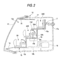
- Fig.2 is a sectional view taken along a line II-II of the vehicle headlamp according to the exemplary embodiment.
- Fig.3 is a vertical sectional view of a first subunit (second subunit) provided at an upper stage light source unit.
- Fig.4 is a vertical sectional view of a third subunit provided at a middle stage light source unit.
- Figs. 5 (a) and 5 (b) illustrate horizontal sectional views of the third subunit (fourth subunit).
- Fig.6 is a perspective view of a lower stage light source unit.
- Fig.7 is a vertical sectional view showing a fifth subunit of the lower stage light source unit.
- Fig.8 is a vertical sectional view showing a sixth subunit of the lower stage light source unit.
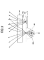
- Fig.9 is a top view of the lower stage light source unit.
- Fig.10 is a view showing a light distribution pattern for low beam formed by the vehicle headlamp of the embodiment.
- Fig.11 is a view showing a light distribution pattern for high beam formed by the vehicle headlamp of the embodiment.
- Figs. 12(a) to 12(d) illustrate schematic sectional views showing a relationship between the third subunit and a light distribution pattern.
- Figs. 13 (a) to 13(d) illustrate other schematic sectional views showing the relationship between the third subunit and the light distribution pattern.
- Figs. 14 (a) to 14 (h) illustrate views showing a relationship between pivoting movement and a light distribution pattern when a diverging member is provided at a light source unit of a directly emitted type.
- Fig. 15 is a control block diagram showing a control related to the vehicle headlamp of the embodiment and switching ON/OFF thereof.
- Fig.16 is a table showing a pattern of controlling to switch ON/OFF by a switch ON/OFF controller.
- Figs. 17(a) to 17(d) illustrate schematic views showing examples of realizing light distribution patterns in AFS.
- Figs. 18(a) to 18(c) illustrate schematic views showing examples of realizing light distribution patterns in AFS.
- Exemplary embodiments of the invention will be described with reference to the accompanying drawings.
- Fig.1 is a front view showing a vehicle headlamp according to an exemplary embodiment of the invention. Fig.2 is a sectional view taken along a line II-II of the vehicle headlamp. Fig.3 is a vertical sectional view of a first subunit provided at an upper stage light source unit. Fig. 4 is a vertical sectional view of a third subunit provided at a middle stage light source unit. Figs.5(a) and 5 (b) illustrate horizontal sectional views of the third subunit. Fig.6 is a perspective view of a lower stage light source unit. Fig.7 is a vertical sectional view showing a fifth subunit of the lower stage light source unit. Fig.8 is a vertical sectional view showing a sixth subunit of the lower stage light source unit. Fig.9 is a top view of the lower stage light source unit.
- A
vehicle headlamp 10 according to the exemplary embodiment is a headlamp attached to, for example, a front end portion of a vehicle, and capable of being switched on and off by selectively switching low beam and high beam. In Fig.1, as an example, a headlamp unit (headlamp unit) attached to a right front side of a vehicle of an automobile or the like is shown as thevehicle headlamp 10. - As shown by Fig. 1 and Fig. 2, the
vehicle headlamp 10 includes a light transmittingtransparent cover 12 and a lamp body (lamp member) 14. Three of light source units (an upper stagelight source unit 20, a middle stagelight source unit 40, a lower stage light source unit 60) are fixedly arranged above asupport member 15 at inside of alamp chamber 10a surrounded by thetransparent cover 12 and thelamp body 14. Anextension 16 is arranged between the threelight source units transparent cover 12 to cover a gap when viewed from a front side of a lamp piece. - The
support member 15 includes three installingportions light source unit 20, the middle stagelight source unit 40, the lower stagelight source unit 60 in this order. Thesupport member 15 is fixed to thelamp body 14 by way of asupport mechanism 17 inclinable by way of an incliningshaft 17a substantially in parallel with a width direction of a vehicle, and apower transmitting shaft 18b connected to a drive shaft 18a of amotor 18 for leveling constituting an actuator. Thesupport mechanism 17, themotor 18 for leveling and thepower transmitting shaft 18b constitute a leveling mechanism for adjusting an angle of attaching thesupportmember 15 to thelamp body 14 in accordance with an output of themotor 14 for leveling. According to the exemplary embodiment, optical axes of the respectivelight source units support member 15 by way of the leveling mechanism. - Next, the respective
light source units - According to the exemplary embodiment, the respective
light source units light source units - First, the upper stage
light source unit 20 will be explained as follows. - The upper stage
light source unit 20 is a light source unit for forming a light distribution for high beam and includes a pair of a first and asecond subunit second subunits portion 15a of thesupport member 15. The first and thesecond subunits - As shown by Fig.3, the
first subunit 20A (similar to thesecond subunit 20B) includes a metal madebase member 21 having substantially an L-like shape in a sectional view thereof, LED (semiconductor light emitting element) 22 as a light source, and a projectinglens 24. - The
base member 21 is arranged on the installingportion 15a of thesupport member 15 at abase member portion 21a thereof extended in a front and rear direction of a vehicle, andLED 22 is fixedly arranged to a vehicle front side of an erectedportion 21b erected from the installingportion 15a. -
LED 22 is a white light emitting diode having a light emitting portion (light emitting chip) 22a having a size of about 1 mm square and is arranged with alight emitting portion 22a for emitting light in a state of being directed to a vehicle front face side. - The projecting
lens 24 is an aspherical lens of a convex lens type for projecting light emitted from thelight emitting portion 22a ofLED 22 to a vehicle front side and is fixed to thebase member 21 at a vicinity of a vehicle front sidefront end portion 21c of thebase member portion 21a. According to the embodiment, a focal point P24 of the projectinglens 24 is constituted to substantially coincide with thelight emitting portion 22a ofLED 22. Therefore, light emitted from thelight emitting portion 22a ofLED 22 is directly incident on the projectinglens 24 and incident light is projected to the front side along an optical axis Ax1 as substantiallyparallel light. That is, the first and thesecond subunits light source unit 20 of the embodiment respectively constitute projector type light source units of a directly emitted type. - Next, the middle stage
light source unit 40 will be explained. - The middle stage
light source unit 40 is a light source unit for forming a portion of a light distribution for low beam, and includes a pair of a third and afourth subunit fourth subunits portion 15b of thesupport member 15. According to the embodiment, the third and thefourth subunits - As shown by Fig.4, the
third subunit 40A (similar to thefourth subunit 40B) includes, for example, abase member 41 substantially in an L-like shape, LED (semiconductor light emitting element) 42 as a light source, a projectinglens 44, areflector 46. - The
base member 41 includes abase member portion 41a extended in the front and rear direction of the vehicle, and an erectedportion 41b is erected from thebase member portion 41a, and an optical mountingportion 41c for fixedly mountingLED 42 and thereflector 46 is extended by being folded from the erectedportion 41b to a rear side of the vehicle. -
LED 42 is a white diode similar toLED 22 and is mounted on a mountingface 41e of the mountingportion 41c in a state of directing alight emitting portion 42a thereof substantially in a vertical upper direction. Thelight emitting portion 42a may be constituted to be arranged with more or less angle in accordance with a shape of the light emitting portion or a light distribution irradiated to a front side. - The
reflector 46 is a reflecting member formed with a reflectingface 46a having a vertical sectional shape substantially in an elliptical shape and having a horizontal sectional shape in a shape of a free curved face based on an ellipse. Thereflector 46 is designed and arranged such that a first focal point P441 thereof is disposed at a vicinity of thelight emitting portion 42a ofLED 42 and a second focal point P442 thereof is disposed at a vicinity of abrow line 41g made by the mountingface 41e of the mountingportion 41c and afront face 41f of the erectedportion 21b. - Light emitted from the
light emitting portion 22a ofLED 22 is reflected by the reflectingface 46a of thereflector 46 and is incident on the projectinglens 44 bypassing a vicinity of the second focal point P442. The third and thefourth subunits face 41e by constituting a boundary line by thebrow line 41g made by the mountingface 41e of the mountingportion 41c and thefront face 41f of the erectedportion 21b. That is, thebrow line 41g constitutes a brightness boundary line of the third and thefourth subunits face 46a of thereflector 46 and further reflected by the mountingface 41e is irradiated to the front side as effective light. Therefore, according to the embodiment, the vehicle front side of the mountingface 41e is provided with an optical shape in which an angle of reflection thereof is set pertinently in consideration of a positional relationship between the projectinglens 44 and thereflector 46. - The projecting
lens 44 is an aspherical lens of a convex lens type for projecting light reflected by the reflectingface 46a of thereflector 46 to the vehicle front side, and is fixed to thebase member 41 at a vicinity of the vehicle front sidefront end portion 41c of thebase member portion 41a. According to the exemplary embodiment, a focal point of the projectinglens 44 is constituted to substantially coincide with the second focal point P442 of thereflector 46. Therefore, light incident on the projectinglens 44 by being reflected by thereflector 46 is projected to the front side as substantially parallel light. That is, the third and thefourth subunits light source unit 40 of the embodiment respectively constitute projector type light source units of a reflecting type for forming to cut converged light. - According to the exemplary embodiment, the third and the
fourth subunits support portion 15d and the installingportion 15b respectively pivotably by way of pivotingshafts shaft 50b on one side is connected to an actuator 19, the third and thefourth subunits shaft fourth subunits - Specifically, the third and the
fourth subunits shafts - According to the exemplary embodiment, a diverging
member 55 is provided at least on one side (left side in the drawing) of sides of a region between the projectinglens 44 and thebrown line 41g, that is, between the projectinglens 44 and thereflector 46. According to the exemplary embodiment, the divergingmember 55 diverges light emitted from the light source and reflected by thereflector 46 further in a side direction. The divergingmember 55 may be arranged only on one side or may be arranged on both sides. When arranged only on one side, it is preferable to provide the diverging member on a side of arranging thevehicle headlamp 10 on the front side of the vehicle, that is, right side when arranged on the right side of the vehicle, or left side when arranged on the left side of the vehicle. - The diverging
member 55 of the exemplary embodiment is a prism diverging lens in which a wall thickness thereof along the front and the rear direction of the vehicle, that is, a direction of propagating light is thickened as being remote from the optical axis Ax2. The divergingmember 55 is fixed to thelamp body 14 or thesupport member 15 by way of a fixed member, not illustrated, at a position on which light is not incident when the third and thefourth subunits member 15, and light is diverged in a side direction. Thereby, a light amount irradiated in the side direction is increased and side optical recognizability can further be promoted. - Next, the lower stage
light source unit 60 will be explained. - The lower stage
light source unit 60 is a light source unit for forming a portion of the light distribution for low beam and includes two of a fifth and asixth subunit cylindrical lens 65. The fifth and thesixth subunits portion 15c of thesupport member 15. - As shown by Fig.6, the fifth and the
sixth subunits base member 90 as a common base member. Thefifth subunit 70 is constituted by arrangingLED 72 on thebase member 90, and thesixth subunit 80 is constituted by includingLED 82 and areflector 86 on thebase member 90. The singlecylindrical lens 65 is arranged on front sides of the fifth and thesixth subunits cylindrical lens 65 is constituted as a projecting lens commonly shared by the twosubunits - According to the
base member 90, as shown by Fig.7, abase member portion 90a extended in the front and rear direction of the vehicle is arranged on the installingportion 15c of thesupport member 15, and an erectedportion 90b is erected from thebase member portion 90a. A steppeddifference portion 90h is formed by cutting off a portion of an upper side of the erectedportion 90b, andLED 72 is mounted to a vehicle front side of the steppeddifference portion 90h. According to the exemplary embodiment, thefifth subunit 70 is constituted byLED 72. -
LED 72 is a white diode similar toLED 22, and alight emitting portion 72a is fixedly arranged on the steppeddifference portion 90h in a state of being directed to the front side in the front and rear direction of the vehicle. Thelight emitting portion 72a may be constituted to be arranged with more or less angle in accordance with a shape of the light emitting portion and the light distribution irradiated to the front side. - The
cylindrical lens 65 is a lens having substantially a cylindrical shape for projecting light emitted from thelight emitting portion 72a of LED 62 to the front side of the vehicle and is fixed to thebase member 90 at a vicinity of a vehicle front sidefront end portion 90c of thebase member portion 90a. Thecylindrical lens 65 is provided with a single piece of a focal line L65 and is constituted such that the focal line L65 is disposed at a vicinity of a lower end of thelight emitting portion 72a ofLED 72 as shown by Fig.7. Therefore, light emitted from thelight emitting portion 72a ofLED 72 is directly incident on projectinglens 65 to project a light distribution pattern including a cutoff line in correspondence with the focal line L65 to the front side along an optical axis Ax3 by constituting substantially parallel light by incident light. That is, thefifth subunit 70 of the exemplary embodiment constitutes a projector type light source unit of a directly emitted type. - On one side in the width direction of the vehicle of the
base member 90, a portion of the erectedportion 90e is folded to bend to a rear side of the vehicle, a mountingportion 90c for mounting to fixLED 82 and thereflector 86 is extended, thereby, thesixth subunit 80 is integrally formed contiguously to thefifth subunit 70. -
LED 82 is a white diode similar toLED 22, and alight emitting portion 82a thereof is mounted on a mountingface 90e of the mountingportion 90c in a state of being directed substantially in a vertical upper direction. Thelight emitting portion 82a may be constituted to arrange with more or less angle in accordance with a shape of the light emitting portion and a light distribution pattern irradiated to the front side. - The
reflector 86 is a reflecting member formed with a reflectingface 86a having a vertical sectional shape substantially in an elliptical shape and a horizontal sectional shape in a free curved face constituting a reference by an ellipse on an inner side thereof. Thereflector 86 is designed and arranged such that a first focal point P861 thereof is disposed at a vicinity of alight emitting portion 82a ofLED 82, and a second focal point is disposed at a vicinity of abrow line 90g made by the mountingface 90e of the mountingportion 90c and afront face 90f of the erected portion. According to the exemplary embodiment, a positional relationship with thecylindrical lens 65 is set such that a focal line L65 of thecylindrical lens 65 is arranged at a vicinity of thebrow line 90g made by the mountingface 90e of the mountingportion 90c and thefront face 90f of the erectedportion 90b. - Therefore, light emitted from the
light emitting portion 22a ofLED 22 is reflected by the reflectingface 86a of thereflector 86 and is incident on thecylindrical lens 65 by passing a vicinity of the focal line L65. Light incident on thecylindrical lens 65 is projected to a front side along an optical axis Ax4 by constituting substantially parallel light in the vertical direction. - The
sixth subunit 80 is constituted to form a cutoff line in a light distribution pattern projected to the front side of the vehicle by selectively cutting light by reflecting a portion of light by the mountingface 90e by constituting a boundary line by the mountingface 90e of the mountingportion 90c and thefront face 90f of the erectedportion 90b. It is preferable that also a portion of light reflected by the reflectingface 86a of thereflector 86 and further reflected by the mountingface 90e is irradiated to the front side as effective light. Therefore, according to the embodiment, the vehicle front side of the mountingface 90e is provided with an optical shape for pertinently setting an angle of reflection in consideration of a positional relationship between thecylindrical lens 65 and thereflector 86. - On the other hand, as shown by Fig.9, with regard to the width direction of the vehicle, light reflected by the reflecting
face 86a of thereflector 86 is incident on thecylindrical lens 65 in a state of being diverged without particularly changing an advancing direction. Therefore, with regard to the width direction of the vehicle, light emitted from thesixth subunit 80 becomes diverged light. In this way, thesixth subunit 80 of the embodiment constitutes a projector type light source unit of a reflecting type. - In this way, according to the lower stage
light source unit 60 of the exemplary embodiment, thefifth subunit 70 and thesixth subunit 80 commonly share the samecylindrical lens 65. Therefore, a number of parts can be reduced in comparison with that in the case of respectively providing the lenses, also spaces of attaching the lens holder, other attaching member and the like can be made to be common and therefore, thefifth subunit 70 and thesixth subunit 80 can be arranged to be proximate to each other. Therefore, the lower stagelight source unit 60 can be downsized by reducing a space occupied by a total of the lower stagelight source unit 60. - Next, an explanation will be given of a basic light distribution pattern formed by the
headlamp 10 of the embodiment in reference to Fig.10 and Fig.11. Thevehicle headlamp 10 of the exemplary embodiment can form a light distribution pattern LP for low beam and a light distribution pattern HP for high beam as basic light distribution patterns. - Fig. 10 is a diagram showing the light distribution pattern LP for low beam formed by the
vehicle headlamp 10 of the exemplary embodiment. - The light distribution pattern LP for low beam is formed by switching on the middle stage
light source unit 40 and the lower stagelight source unit 60. - Specifically, by switching on the third, the
fourth subunits light source unit 40, light is irradiated to a narrow first region D1 at a vicinity of an intersection of H-V lines on a front side of a front face of the vehicle. The first region D1 includes a cutoff line CL1 substantially in a Z-like shape formed in correspondence with theblow lines 41g formed at the third, thefourth subunit - By switching on the fifth, the
sixth subunits light source unit 60, a second region D2 and a third region D3 extended in a width direction of the vehicle (H line direction) are formed respectively downward from the first region D1. - The second region D2 formed by the
fifth subunit 70 is formed at a downward vicinity of the first region D1 to partially overlap the first region D1. An upper end of the second region D2 is formed with a cutoff line CL2 formed by thefifth subunit 70. According to the embodiment, the cutoff line CL2 is set to be projected to the front side to be continuous to the cutoff line CL1 of the first region D1. - The third region D3 formed by the
sixth subunit 80 is formed downward from the second region D2 to partially overlap the second region D2. Since thesixth subunit 80 is the reflecting type projector light source unit, light is irradiated in a wide direction in the vertical direction more easily than thesixth subunit 70 constituting the directly emitted type projector light source unit. Therefore, according to the embodiment, there is constructed a constitution of forming the third region D3 as a short distance diverging region for promoting short distance optical recognizability by thesixth subunit 80 and forming the second region D2 as a long distance diverging region for promoting long distance optical recognizability by thefifth subunit 70. - In this way, according to the exemplary embodiment, the light distribution pattern LP for low beam is formed by combining the first region D1, the second region D2 and the third region D3 formed by the middle stage
light source unit 40 and the lower stagelight source unit 60. - Fig. 11 is a diagram showing the light distribution pattern HP for high beam formed by the
vehicle headlamp 10 of the exemplary embodiment. - The light distribution pattern HP for high beam is formed by switching on the middle stage
light source unit 40 and the lower stagelight source unit 60 as well as the upper stagelight source unit 20. - Specifically, there is constructed a constitution in which by switching on the upper stage light source unit, a fourth region D4 is irradiated overlappingly on the first region D1, the second region D2 and the third region D3 formed by the middle stage
light source unit 40 and the lower stagelight source unit 60. The fourth region D4 is a light distribution pattern diverged in an up and down direction and in a left and right direction centering on a vicinity of an intersection of H-V lines. According to the light distribution pattern HP for high beam, a light amount of a total is increased by forming the fourth region D4 to thereby promote remote optical recognizability. - According to the exemplary embodiment, in forming the light distribution pattern HP for high beam, there is constructed a constitution of further promoting remote optical recognizability by arranging the hot zone Hz at a vicinity in a horizontal direction 0° by respectively shifting the optical axes Ax2 slightly (0.5 through 5°) in the right direction by pivoting the middle stage
light source units light source unit 40. - Next, an explanation will be given of a relationship between pivoting movement of the third, the
fourth subunits light source unit 40 according to the exemplary embodiment and the light distribution pattern in reference to Figs.12(a) to 12(d) and Figs.13(a) to 13(d). - Figs.12 (a) to 12 (d) illustrate schematic sectional views showing a relationship between the
third subunit 40a and the light distribution pattern. Specifically, Fig.12(a) is a schematic horizontal sectional view when thethird subunit 40a (the same also in the case of thefourth subunit 40b) is pivoted in a left direction by 15° in a case of a constitution of not arranging the divergingmember 55, and Fig.12(b) is a schematic diagram showing the light distribution pattern. Fig.12(c) is a schematic horizontal sectional view when thethird subunit 40a is pivoted in the left direction by 15° in a case of a constitution of being arranged with the divergingmember 55, and Fig.12(d) is a schematic diagram showing the light distribution pattern. In Fig.12, a prism diverging lens is used as the divergingmember 55. - As is known by comparing Fig.12(a) and Fig.12(c), when the diverging
member 55 is arranged, in a state of pivoting thethird subunit 40a, a portion of light is incident on the divergingmember 55 immediately before being incident on the projectinglens 44 and a direction of advancing light is bent to a pivoting side. Therefore, light emitted from the projectinglens 44 is diverged more in a side direction when the divergingmember 55 is arranged. - When the specific light distributionpatterns are compared, whereas in the light distribution pattern D11 shown in Fig. 12 (b), a rise position of the cutoff line is inclined by 15° the same as the pivoting angle, in the light distribution pattern D12 shown in Fig. 12 (d), a rise position of the cutoff line is inclined by 20° larger than the pivoting angle by 5°. This is because light is diverged in the side direction by the diverging
member 55. As a result, it is known that a total of the light distribution pattern is diverged to extend in the vehicle width direction. - Figs.13(a) to 13 (d) illustrate other schematic sectional views showing the relationship between the
third subunit 40a and the light distribution pattern. - Specifically, Fig.13(a) is a schematic horizontal sectional view when the
third subunit 40a is pivoted in the left direction by 20° in a case of a constitution of not arranging the divergingmember 55, and Fig.13(b) is a schematic diagram showing the light distribution pattern. Fig.13(c) is a schematic horizontal sectional view when thesubunit 40a is pivoted in the left direction by 20° in a case of a constitution of arranging the divergingmember 55, and Fig.13(d) is a schematic diagram showing the light distribution pattern. In Fig.13, there is used a step diverging lens formed with a plurality ofcylindrical steps 55a on the reflector side as the diverging member 53. - As is known by comparing Fig.13(a) and Fig.13(c), when the diverging
member 55 is arranged, in a state of pivoting thethird subunit 40a, a portion of light is incident on the divergingmember 55 immediately before being incident on the projectinglens 44 and a direction of advancing light is bent to the pivoting side. Therefore, light emitted from the projectinglens 44 is more diverged in the side direction when the divergingmember 55 is arranged. When the step diverging lens is used as the divergingmember 55, a portion of light is bent also in a direction reverse to the pivoting side, as a result, light is diverged in both of left and right directions. - When the specific light distributionpatterns are compared, whereas according to a light distribution pattern D13 shown in Fig.13(b), a rise position of the cutoff line is inclined by 20° the same as the pivoting angle, according to a light distribution pattern D14 shown in Fig.13(d), a rise position of the cutoff line is inclined by 15° smaller than the pivoting angle by 5°. As shown by Fig.13(d), a region of the light distribution pattern D14 is extended considerably to left side by about 35°. This is because light is diverged both in left and right directions by the diverging
member 55. As a result, it is known that a total of the light distribution pattern is diverged to extend in the vehicle width direction. - In this way, when the diverging
member 55 is arranged, light is diverged and therefore, the light distribution pattern can be shifted in the side direction by the pivoting angle or more. Therefore, even in a case of an arrangement restricting amounts of pivoting the third, thefourth subunits member 55 can diverge to irradiate light in the side direction by the pivoting angle or more. Conversely, the pivoting amount can be made to be small in comparison with an amount of shifting the light distribution pattern and therefore, the total of the light source unit can be made to be compact by reducing a space for pivoting. Since the pivoting amount is small, actuators for driving the third, thefourth subunits - Although in the above-described explanation, there is shown a constitution of attaching the diverging
members 55 to the third, thefourth subunits light source unit 40 may be constituted by respectively replacing the third, thefourth subunits light source units 40c of the directly emitted type as shown by Figs.14(a) to 14(h). - Figs. 14 (a) to 14 (h) illustrate views showing a relationship between the pivoting movement and the light distribution pattern when the diverging member is provided to the directly emitted type light source, Figs. 14 (a) and 14 (b) are respectively views showing the light source unit and the light distribution pattern when the pivoting angle is 0°, Figs. 14 (c) and 14(d) are respectively views showing the light source unit and the light distribution pattern when the pivoting angle is 10°, Figs. 14 (e) and 14 (f) are respectively views showing the light source unit and the light distribution pattern when the pivoting angle is 20°, and Figs. 14 (g) and 14 (h) are respectively views showing the light source unit and the light distribution pattern when the pivoting angle is 30°.
- The
light source unit 40c of the directly emitting type is constructed by a constitution similar to that of thefifth subunit 70 shown in Fig. 7 and is constructed by a constitution of arranging alight emitting portion 40c of LED at a vicinity of a focal point of a projectinglens 40c. Even in the constitution, as shown by Figs. 14(c) and 14(d), when a total of the unit is inclined by 10°, a total of the light distribution pattern is shifted in the side direction on the left side by 10° and a length in the vehicle width direction (horizontal direction) of the light distribution pattern is extended. The tendency is increased further when the total of the unit is inclined by 20° as shown by Figs. 14(e) and 14(f), further, it is known that as shown by Figs. 14(g) and 14(h), when the total of the unit is inclined by about 30° and the divergingmember 55 is extended to a degree of crossing the optical axis Ax, the light distribution pattern is extended not only to the left side but also to the right side. - In this way, even in the directly emitted type light source unit, when the diverging
member 55 is arranged, light is diverged and therefore, the light distribution pattern can be shifted in the side direction by the pivoting angle or more. Therefore, even in an arrangement of restricting the pivoting amount of the light source unit, the divergingmember 55 can diverge to irradiate light in the side direction by the pivoting angle or more. Conversely, the pivoting angle can be reduced in comparison with the amount of shifting the light distribution pattern and therefore, a total of the light source unit can be made to be compact by reducing the space for pivoting. Since the pivoting amount is small, the actuator for driving the light source unit can also be downsized. - Next, a detailed explanation will be given of switch ON/OFF of the
vehicle headlamp 10 of the embodiment in reference to Fig.15. - Fig.15 is a control block diagram showing a control related to the
vehicle headlamp 10 of the embodiment and switch ON/OFF thereof. A switch ON/OFF control of thevehicle headlamp 10 of the embodiment is carried out by a switch ON/OFF controller 100, asteering angle sensor 110, avehicle speed sensor 120, a high/low switching switch 130, abrightness sensor 140, arain sensor 150 and avehicle height sensor 160 for outputting various signals to the switch ON/OFF controller 100. All of these are similarly mounted to a vehicle mounted with thevehicle headlamp 10. - The switch ON/
OFF controller 100 is a control center portion for controlling to switch ON/OFF, increase light and reduce light of respectives of the respectivelight source units vehicle headlamp 10, controls respective pivoting angles of the third and thefourth subunits light source unit 40, and adjusts leveling by controlling themotor 14 for leveling based on outputs from the various sensors and the switch mentioned above. The switch ON/OFF controller 100 is constituted to automatically produce a light distribution adapted to a running situation. That is, according to the exemplary embodiment, AFS (Adaptive Front lighting System) is realized by using thevehicle headlamp 10. - Next, the sensors and the switches will be explained.
- The
steering angle sensor 110 is a sensor for detecting an angle of turning a vehicle, and, for example, a steering sensor for detecting a steering operation or the like can be used therefor. By a detected signal of thesteering sensor 110, it can be determined whether the vehicle advances straight. - The
vehicle speed sensor 120 is a sensor for detecting a speed of the vehicle. By a detected signal of thevehicle speed sensor 120, the speed of the vehicle can be determined and it can be determined whether the vehicle is running on a general road or running on a motorway of an automobile exclusive road or the like. - The high/
low switching switch 130 is a switch for switching high beam and low beam and is switched in accordance with an operation of a driver driving the vehicle. - The
brightness sensor 140 is a sensor for detecting a brightness of a surrounding of the vehicle. For example, by using the brightness sensor, it can be determined whether the vehicle runs on a dark country road or the like, or runs in a relatively bright urban area. - The
rain sensor 150 is a sensor for detecting whether rain falls. By a detected signal of the sensor, it can be determined whether the vehicle runs under rainy weather. - The
vehicle height sensor 160 constitutes a portion of means for detecting a pitch angle of the vehicle. According to the exemplary embodiment, the switch ON/OFF controller 100 carries out automatic leveling by controlling themotor 18 for leveling based on an output signal outputted by thevehicle height sensor 160. - The switch ON/
OFF controller 100 of the exemplary embodiment forms a light distribution in accordance with a situation by controlling to switch ON/OFF upper stage light source unit 20 (thefirst subunit 20a and thesecond subunit 20b) forming a light distribution for high beam, the middle light source unit 40 (thethird subunits fifth subunit 70 of the lower stagelight source unit 60 for forming long distance diverging light, the sixsubunit 80 of the lower stagelight source unit 60 for forming short distance diverging light independently from each other based on the outputs from the sensors. - Fig.16 is a table showing a pattern of the switch ON/OFF control of the switch ON/
OFF controller 100. - First, when the high/
low switching switch 130 is selected to low, the switch ON/OFF controller 100 forms the low beam light distribution pattern shown in Fig.10 by not switching on the upper stagelight source unit 20 and switching on otherlight source units - When the high/
low switching switch 130 is selected to high, the switch ON/OFF controller 100 forms the high beam light distribution by over lapping the light distribution pattern formed by the upper stagelight source unit 20 on the low beam light distribution pattern by further switching on the upper stagelight source unit 20. At this occasion, thethird subunit 40a and thefourth subunit 40b of the middlelight source unit 40 may be pivoted in the right direction to thereby shift the first region D1 formed by the middle stagelight source unit 40 to a vicinity of an intersection of H-V lines as shown by Fig.11. At this occasion, the switch ON/OFF controller 100 may increase the light amount to the front side by increasing light emitting amounts of thelight emitting portions 42a of therespective subunits light source unit 40. - Next, an explanation will be given of various modes of a variable front light distribution system (AFS) realized in a low beam light distribution in reference to Figs. 17(a) to 17(d) and Figs. 18(a) to 18(c).
- Figs. 17(a) to 17(d) and Figs. 18(a) to 18(c) illustrate schematic views respectively showing examples of realizing light distribution patterns for AFS.
- First, a curve mode will be explained.
- The switch ON/
OFF controller 100 determines that the vehicle is going to a curve when, for example, the vehicle is at a predetermined speed and a steering angle is a predetermined value or more based on signals from thesteering angle sensor 110 and thevehicle speed sensor 120 in switching on low beam. In this case, the switch ON/OFF controller 100 realizes a light distribution pattern based on the curve mode. - Specifically, in the curve mode, the switch ON/
OFF controller 100 makes the upper stagelight source unit 20 stay to be switched OFF and switches ON the otherlight source units OFF controller 100 pivots the third and thefourth subunits light source unit 40 respectively in left and right inverse directions by about 20°. Thereby, as shown by Fig.17(a), the first region D1 which has been irradiated to a center is divided into two to respectively irradiate in left and right directions. Thereby, left and right optical recognizability in curving is promoted. In the curve mode, the third and thefourth subunits fourth subunits steering angle sensor 110 and thevehicle speed sensor 120. - Next, a town mode will be explained.
- The switch ON/
OFF controller 100 determines that the vehicle is running in an urban area when, for example, the vehicle runs at a predetermined speed or lower in a region having a predetermined brightness based on the signals from thevehicle speed sensor 120 and thebrightness sensor 140 in switching on low beam. In this case, the switch ON/OFF controller 100 realizes a light distribution pattern based on the town mode. Here, the town mode signifies a light distribution pattern suitable for running in an urban area having a high possibility that a walker walks on a sideway or the like. - Specifically, in the town mode, the switch ON/
OFF controller 100 makes the upper stagelight source unit 20 stay to be switched OFF and switches ON the otherlight source units OFF controller 100 pivots the third and thefourth subunits light source unit 70 respectively in left and right inverse directions by about 45°. Thereby, as shown by Fig.17(b), the first region D1 which has been irradiated to a center is divided into two to respectively irradiate in left and right side directions. Thereby, light is positively illuminated to road shoulders or the like to promote optical recognizability of a walker walking on, for example, the road shoulder. - In the town mode, as a way of producing other light distribution pattern, as shown by Fig.17(c), the third and the
fourth subunits light source unit 40 may respectively be pivoted only to, for example, the left side by an angle exceeding 20° to thereby diverge light to the road shoulder side by the divergingmembers 55. Also in this case, light is positively illuminated to the road shoulder or the like to promote optical recognizability of a walker walking on, for example, the road shoulder. - Next, a motorway mode will be explained.
- The switch ON/
OFF controller 100 determines that the vehicle is running on the automobile exclusive road when, for example, the vehicle runs by a predetermined speed or more based on the signal from thevehicle speed sensor 120 in switching on lowbeam. In this case, the switch ON/OFF controller 100 realizes a light distribution pattern based on the motorway mode. Here, the motorway mode signifies a light distribution pattern suitable for running on the automobile exclusive road where a walker is not present. - Specifically, in the motorway mode, the switch ON/
OFF controller 100 makes the upper stagelight source unit 20 stay to be switched OFF and switches ON the otherlight source units OFF controller 100 angularly displaces all of thelight source units support member 15 by operating themotor 18 for leveling (by 0.34°, by a range of about 0.1° through 0.5° as an example) (refer to Fig.17(d)). Thereby, light at a vicinity of H line is intensified to promote remote optical recognizability. - In the motorway mode, the switch ON/
OFF controller 100 may further increase the light amount to the front side by increasing the light emitting amounts from therespective units light source unit 40 and thefifth subunit 70 for diverging in a long distance. At this occasion, it is preferable to reduce the light emitting amount from the sixth subunit by reducing power supplied to thesixth subunit 80 for diverging in a short distance. Thereby, the light amount illuminated to the near front side of the vehicle is reduced, light irradiated to a vicinity of H line is relatively emphasized to further promote long distance optical recognizability. - Next, the rain mode will be explained.
- When the switch ON/
OFF controller 100 determines that rain falls in running at, for example, a predetermined speed based on, for example, signals from thevehicle speed sensor 120 and therain sensor 150 in switching on low beam, the switch ON/OFF controller 100 realizes a light distribution pattern based on the rain mode. Here, the rain mode signifies a light distribution pattern with an object of promoting optical recognizability under rainy weather. - Specifically, in the rain mode, the switch ON/
OFF controller 100 makes the upper stagelight source unit 20 stay to be switched OFF and switches ON the otherlight source units OFF controller 100 angularly displaces all of thelight source units support member 15 by operating themotor 18 for leveling (by 0.34°, by a range of about 0.1° through 0.5° as an example). Thereby, light at a vicinity of H line is intensified to promote remote optical recognizability. - In the rain mode, the switch ON/
OFF controller 100 may further increase the light amount on the front side by increasing the light emitting amounts from therespective units light source unit 40 and thefifth subunit 70 for diverging in a long distance. At this occasion, it is preferable to reduce the light emitting amount from the sixth subunit by reducing power supplied to thesixth subunit 80 for diverging in a short distance. Thereby, the light amount illuminated to the near front side of the vehicle is reduced, light irradiated to a vicinity of H line is relatively emphasized, and remote distance optical recognizability is further promoted. Although there is a case of deteriorating optical recognizability by randomly reflecting light illuminated to the near front side of the vehicle on a road face under rainy weather, light reflected randomly can be restrained by reducing the light amount in this way. As an optional choice, as shown by Fig.18(a), there may be constructed a constitution of restraining random reflection further positively by preventing the third region D3 from being formed by not switching thesixth subunit 80. - In the rain mode, there may be constructed a constitution in which the switch ON/
OFF controller 100 increases to supply power to a light source unit of thethird subunit 40a and thefourth subunit 40b which is disposed on the right side in the direction of advancing the vehicle to thereby increase the light amount and pivots the light source unit in the left direction and increases light of a light source unit of thethird subunit 40a and thefourth subunit 40b which is disposed on the left side in the direction of advancing the vehicle. In this way, as shown by Fig.18(b), the region of the first region D1 is shifted in the left side direction and side optical recognizability can simultaneously be promoted. - In the rain mode, instead of constructing the constitution as shown by Fig.18(b), there may be constructed a constitution in which power is increased to supply to the light source unit of the
third subunit 40a and thefourth subunit 40b which is disposed on the right side in the direction of advancing the vehicle and pivots the light source unit by an angle exceeding 20° in the left direction to thereby positively diverge light in the left direction by the divergingmember 55 and only light of the light source unit of thethird subunit 40a and thefourth subunit 40b which is disposed on the left side in the direction of advancing the vehicle is increased. In this case, as shown by Fig.18(c), the region of the first region D1 is further shifted in a state of being diverged in the left side direction and side optical recognizability can further be promoted. - As has been explained above, the
vehicle headlamp 10 of the exemplary embodiment includes the upper stagelight source unit 20, the middle stagelight source unit 40, the lower stagelight source unit 60 as a plurality of light source units respectively including the light emitting portions as the light sources, and optical members of the projecting lenses, the reflectors and the like for irradiating light from the light emitting portions along the optical axes. The upper stagelight source unit 20, the middle stagelight source unit 40, the lower stagelight source unit 60 are provided in thelamp body 14 constituting the lamp member by way of thesupport member 15, and the low beam light distribution pattern is formed on the front side of the vehicle by overlapping light from the respectivelight source units light source unit 40 constituting at least one of the plurality oflight source units lamp body 14 to be able to change the optical axis independently from the other opticallight source units - Therefore, by pertinently changing the optical axis of the middle stage
optical unit 40 and changing an irradiating region, an optimum low beam light distribution pattern can be formed in various situations. In changing the low beam light distribution pattern, only four of the light emitting portions are controlled at maximum, and therefore, various light distribution patterns can be realized without increasing a number of the light sources more than necessary. It is not necessary to install the light source unit including a number of the light emitting portions, and therefore, the vehicle headlamp can be downsized, a number of the light emitting portions can be made to be smaller than that in the background art and therefore, power consumption can be restrained. - As a specific constitution, the middle stage
light source unit 40 constituting the optical axis variable light source unit can form a light converging region including a skewed cutoff line in the low beam light distribution pattern. According to the exemplary embodiment, a position of irradiating the light converging region can pertinently be changed, and therefore, light can concentratedly be irradiated to a necessary portion in accordance with a situation, and the light distribution patterns in accordance with various situations of the curve mode, the town mode, the motor way mode or the rain mode can be formed. - The middle stage
light source unit 40 constituting the optical axis light source unit changes a position of the light converging region between the center of the front of the vehicle and the side of the front side of the vehicle by moving the optical axis substantially in the horizontal direction. By constituting in this way, light can be concentrated on the center portion of the front side of the vehicle, or light can be concentrated on the side portion on the front side of the vehicle as necessary. In order to move the optical axis in the horizontal direction, only the total of the light source unit 40 (according to the exemplary embodiment, the third and thefourth subunits - The middle
light source unit 40 constituting the optical axis variable light source unit is constituted by two of the third and thefourth subunits - Each of the third and the
fourth subunits lens 44c as an optical member, arranged with alight emitting portion 42c as a light source at a vicinity of a focal point of the projectinglens 44c for irradiating light directly from thelight emitting portion 42c to the font side. By constituting the light source unit of the directly emitted type, a reflector can be omitted, or an installing space thereof can be reduced. When constituting the light source unit of the directly emitted type, light can easily be concentrated on an extremely narrow region and therefore, the light source unit can preferably be used when light is intended to irradiate to pinpoint a certain narrow region. - As shown by Figs.4, 5, 12, 13, the third and the
fourth subunits reflector 46 for reflecting light from the projectinglens 44 as the optical member and thelight emitting portion 42c to a vicinity of the focal point of the projectinglens 44 for irradiating light reflected from thereflector 46 to the front side. When constituted as the light source unit of the reflecting type, the reflector is needed, some degree of installing space needs to be ensured, however, by pertinently designing the reflectingface 46a of thereflector 46, light can easily be controlled, and therefore, light of a pertinent light amount can easily be concentrated on a necessary region. - Further, according to the exemplary embodiment, each of the third and the
fourth subunits light source unit 40 constituting the optical axis variable light source unit is provided with the divergingmember 55 for diverging light emitted from thelight emitting portion 42a between the projectinglens 44 and thelight emitting portion 42a. The divergingmember 55 is provided at a position on which light is incident when the third and thefourth subunits member 55 only in being pivoted. - Therefore, when light is irradiated to the center region which needs a clear cutoff line, the diverging
member 55 does not hamper light from being propagated and when light is irradiated to the side region which does not need so clear cutoff line, the irradiating region can be widened by the pivoting angle or more. Therefore, the vehicle headlamp having high side optical recognizability capable of irradiating light over a wide side region can be constituted. - As the diverging
member 55, the prism diverging lens in which the wall thickness along the direction of propagating light is thickened as being remote from the optical axis can be used. By using the prism diverging lens, the irradiating region can be widened by the pivoting angle or more and therefore, side optical recognizability of the vehicle can be promoted. - According to the exemplary embodiment, as the diverging
member 55, the step diverging lens formed with a plurality of steps can be used. By using the step diverging lens, the irradiating region can be widened over on both left and right sides and therefore, light can be irradiated evenly over the wide region and side optical recognizability of the vehicle can be promoted. The prism diverging lens and the step diverging lens can be used selectively in accordance with a diverging pattern intended by a designer, and when other diverging pattern is intended to provide, other lens for diverging, or other kind of a diverging member may be used. - According to the exemplary embodiment, the
light source unit 60 in the plurality of thelight source units cylindrical lens 65 having the focal line extended in the horizontal direction, the fifth subunit (first subunit) 70 for making light incident on thecylindrical lens 65, and the sixth subunit (second subunit) 80. Thefifth subunit 70 is a directly emitted type subunit including thelight emitting portion 72a (first light emitting element) for emitting light to a vicinity of the focal line of thecylindrical lens 65 for irradiating light to the front side of thecylindrical lens 65. Thesixth subunit 80 is the reflecting type subunit including the light emitting portion (second light emitting element) 82a for emitting light and thereflector 86 for reflecting light from thelight emitting portion 82a to a vicinity of the focal line of thecylindrical lens 65 for irradiating light to the front side by way of thecylindrical lens 65. - That is, according to the exemplary embodiment, the
fifth subunit 70 and thesixth subunit 80 commonly share the single cylindrical lens and therefore, in comparison with a case of providing respectively separate lenses, a number of parts can be reduced and also spaces of attaching members of a lens holder and the like can be made common, and therefore, thefifth subunit 70 and thesixth subunit 80 can be arranged to be proximate to each other. Therefore, the lower stagelight source unit 60 can be downsized by reducing a space occupied by a total of the lower stagelight source unit 60. - According to the exemplary embodiment, the light distribution region D3 projected to the front side from the
sixth subunit 80 by way of thecylindrical lens 65 is diverged in the vertical direction more than the light distribution region D2 projected to the front side from thefifth subunit 70 by way of thecylindrical lens 65. This is mainly derived from a difference between the directly emitted type and the reflecting type and various light distribution patterns can be realized even when the single cylindrical lens is used. - According to the exemplary embodiment, the two light emitting
portions portions single base member 90 to be assembled with other member, and therefore, assembling performance can be promoted and accuracies of positioning the two light emitting portions can be promoted by constituting a reference by thesingle base member 90. - The
light emitting portion 72a is arranged at a vicinity of the focal line of thecylindrical lens 65 and above the focal line. Therefore, light projected to the front side by way of thecylindrical lens 65 can be provided with a cutoff line, for example, a diverging region constituting a portion of a horizontal line at a vicinity of H line needing a clear brightness boundary can be formed. - Although according to the above-described explanation, the
vehicle headlamp 10 has been explained as the vehicle headlamp which can be used both for high beam and low beam, the invention is not limited thereto but, for example, a vehicle headlamp exclusively for low beam can also be constituted by constituting thevehicle headlamp 10 by, for example, excluding the upper stagelight source unit 20 and using only the middle stagelight source unit 40 and the lower stagelight source unit 60. Also in this case, principal operation and effect are the same as those of the case in which thevehicle headlamp 10 can be used both for high beam and low beam. - It will be apparent to those skilled in the art that various modifications and variations can be made to the described exemplary embodiments of the present invention without departing from the spirit or scope of the invention. Thus, it is intended that the present invention cover all modifications and variations of this invention consistent with the scope of the appended claims and their equivalents.
Claims (10)
- A vehicle headlamp comprising:a plurality of light source units, each light source unit including a light source and an optical member for irradiating light from the light source along an optical axis; anda lamp member that supports the plurality of light source units, wherein a light distribution pattern for a low beam is formed on a front side of a vehicle by overlapping lights from the respective light source units;wherein at least one of the plurality of light source units is an optical axis variable light source unit supported by the lamp member so as to be able to change the optical axis independently from the other optical axes of the other light source units.
- The vehicle headlamp according to Claim 1, wherein the optical axis variable light source unit forms a light converging region having a skewed cutoff line in the light distribution pattern for the low beam.
- The vehicle headlamp according to Claim 1, wherein the optical axis variable light source unit changes a position of the light converging region between a center of the front side of the vehicle and a side of the front side of the vehicle by moving the optical axis substantially in a horizontal direction.
- The vehicle headlamp according to Claim 1, wherein the optical axis variable light source unit is a light source unit of a directly emitting type, wherein a projecting lens is provided as the optical member, the light source is arranged at a vicinity of a focal point of the projecting lens, and light from the light source is directly irradiated to the front side.
- The vehicle headlamp according to Claim 1, wherein the optical axis variable light source unit is a light source unit of a reflecting type including a projecting lens and a reflector for reflecting light from the light source to a vicinity of a focal point of the projecting lens as the optical members for irradiating light reflected from the reflector to the front side.
- The vehicle headlamp according to Claim 1, wherein the optical axis variable light source unit is constituted to be able to increase or reduce an outputted light amount.
- The vehicle headlamp according to claim 1, wherein the optical axis variable light source unit is pivotably supported by the lamp member to move the optical axis substantially along a horizontal face;
wherein the optical axis variable light source unit is provided with a diverging member for diverging light emitted from the light source between the projecting lens and the light source; and
wherein light is diverged by the diverging member when the optical axis variable light source unit is pivoted and the optical axis is moved to irradiate light to a side of the front side of the vehicle from a position of irradiating light from a center of the front side of the vehicle. - The vehicle headlamp according to Claim 7, wherein the diverging member is a prism diverging lens in which a wall thickness thereof along a direction of propagating light is thickened as being remote from the optical axis.
- The vehicle headlamp according to Claim 7, wherein the diverging member is a step diverging lens formed with a plurality of steps.
- The vehicle headlamp according to Claim 7, wherein the optical axis variable light source unit forms a light converging region having a skewed cutoff line in the low beam light distribution pattern.
Applications Claiming Priority (2)
| Application Number | Priority Date | Filing Date | Title |
|---|---|---|---|
| JP2006030464A JP2007213877A (en) | 2006-02-08 | 2006-02-08 | Vehicular headlamp |
| JP2006030465A JP2007213878A (en) | 2006-02-08 | 2006-02-08 | Vehicular headlamp |
Publications (2)
| Publication Number | Publication Date |
|---|---|
| EP1818601A1 true EP1818601A1 (en) | 2007-08-15 |
| EP1818601B1 EP1818601B1 (en) | 2010-05-19 |
Family
ID=37968483
Family Applications (1)
| Application Number | Title | Priority Date | Filing Date |
|---|---|---|---|
| EP07101931A Expired - Fee Related EP1818601B1 (en) | 2006-02-08 | 2007-02-07 | Vehicle headlamp |
Country Status (4)
| Country | Link |
|---|---|
| US (1) | US7766524B2 (en) |
| EP (1) | EP1818601B1 (en) |
| KR (1) | KR100868720B1 (en) |
| DE (1) | DE602007006563D1 (en) |
Cited By (4)
| Publication number | Priority date | Publication date | Assignee | Title |
|---|---|---|---|---|
| EP1980447A1 (en) * | 2007-04-13 | 2008-10-15 | Valeo Vision | Compact lighting device performing a turning code function |
| EP2998647A4 (en) * | 2013-05-17 | 2017-04-19 | Ichikoh Industries, Ltd. | Vehicle headlamp |
| FR3073178A1 (en) * | 2017-11-08 | 2019-05-10 | Psa Automobiles Sa | MAIN BEAM LIGHTING DEVICE AND NARROW HARNESS PRODUCED BY AN ADJUSTABLE ASSEMBLY BASED ON THE POSITION OF AN OBSTACLE DETECTED BEFORE A VEHICLE |
| CN111344517A (en) * | 2017-11-08 | 2020-06-26 | 标致雪铁龙汽车股份有限公司 | Lighting device with a main light beam and a narrow light beam that can be directed according to the position of an obstacle detected in front of the vehicle |
Families Citing this family (34)
| Publication number | Priority date | Publication date | Assignee | Title |
|---|---|---|---|---|
| JP4926771B2 (en) * | 2007-03-15 | 2012-05-09 | 株式会社小糸製作所 | Vehicle lamp unit |
| JP5009031B2 (en) * | 2007-04-10 | 2012-08-22 | 株式会社小糸製作所 | Vehicle lamp unit |
| JP2008277007A (en) * | 2007-04-26 | 2008-11-13 | Koito Mfg Co Ltd | Vehicular lamp |
| KR100989390B1 (en) * | 2008-02-15 | 2010-10-25 | 에스엘 주식회사 | Head lamp assembly for vehicle |
| DE102008021688A1 (en) * | 2008-04-30 | 2009-11-05 | Hella Kgaa Hueck & Co. | Vehicle's e.g. passenger car, exterior lighting controlling method, involves performing automatic switching-off of headlamp and switching-on of light by controller when environment brightness is larger than prior fixed minimum value |
| JP5352263B2 (en) | 2009-02-06 | 2013-11-27 | 株式会社小糸製作所 | Vehicle lighting |
| KR20110063211A (en) * | 2009-12-04 | 2011-06-10 | 현대자동차주식회사 | High-beam methon and device of led head lamp |
| JP5823856B2 (en) * | 2011-12-27 | 2015-11-25 | 株式会社小糸製作所 | Vehicle lighting |
| CN103978924A (en) * | 2013-02-07 | 2014-08-13 | 李育全 | Auxiliary guiding system for driving direction |
| EP2971942B1 (en) | 2013-03-15 | 2018-05-30 | Whelen Engineering Company, Inc. | Compact multi-function led lighthead |
| KR101605702B1 (en) | 2013-08-13 | 2016-03-23 | 에스엘 주식회사 | Automotive lamp and method for controlling the automotive lamp |
| KR101615540B1 (en) * | 2013-12-17 | 2016-04-26 | 에스엘 주식회사 | Lamp for vehicles |
| FR3016570B1 (en) * | 2014-01-17 | 2016-01-29 | Peugeot Citroen Automobiles Sa | SWITCHABLE CIRCUIT LIGHTING DEVICE FOR MOTOR VEHICLE |
| FR3016567B1 (en) * | 2014-01-17 | 2016-01-29 | Peugeot Citroen Automobiles Sa | REVERSIBLE LIGHTING DEVICE FOR MOTOR VEHICLE |
| FR3016569B1 (en) * | 2014-01-17 | 2016-01-29 | Peugeot Citroen Automobiles Sa | DIFFUSION SIGNALING DEVICE FOR MOTOR VEHICLE |
| FR3016685B1 (en) * | 2014-01-17 | 2016-01-29 | Peugeot Citroen Automobiles Sa | COOLING LIGHTING DEVICE FOR MOTOR VEHICLE |
| FR3016566B1 (en) * | 2014-01-17 | 2016-01-29 | Peugeot Citroen Automobiles Sa | PENDULUM LIGHTING DEVICE FOR MOTOR VEHICLE |
| FR3016568B1 (en) * | 2014-01-17 | 2016-01-29 | Peugeot Citroen Automobiles Sa | MOBILE LENS LIGHTING DEVICE FOR MOTOR VEHICLE |
| KR101600564B1 (en) * | 2014-03-28 | 2016-03-07 | 에스엘 주식회사 | Automotive lamp |
| WO2016013340A1 (en) | 2014-07-25 | 2016-01-28 | スタンレー電気株式会社 | Lighting fixture for vehicle |
| DE102014226650B4 (en) * | 2014-12-19 | 2023-05-25 | Osram Gmbh | lamp |
| JP6516495B2 (en) * | 2015-02-13 | 2019-05-22 | 株式会社小糸製作所 | Vehicle lamp |
| FR3045781B1 (en) * | 2015-12-18 | 2020-03-06 | Valeo Vision Belgique | LUMINOUS MODULE, PARTICULARLY FOR HIGH LIGHTS WITH SMOOTH APPEARANCE |
| JP6741438B2 (en) * | 2016-02-17 | 2020-08-19 | 株式会社小糸製作所 | Vehicle lighting |
| JP6695165B2 (en) * | 2016-02-23 | 2020-05-20 | 株式会社小糸製作所 | Vehicle lighting unit |
| JP6621697B2 (en) * | 2016-03-30 | 2019-12-18 | 株式会社小糸製作所 | Vehicle lighting |
| JP6691806B2 (en) * | 2016-04-06 | 2020-05-13 | 株式会社小糸製作所 | Vehicle lighting |
| CN105757576B (en) * | 2016-04-07 | 2018-08-07 | 广州市佑航电子有限公司 | A kind of portable lamp |
| US11060687B2 (en) * | 2016-09-13 | 2021-07-13 | Honda Motor Co., Ltd. | Headlight device including a main light source and an auxiliary light source |
| FR3056683B1 (en) * | 2016-09-26 | 2019-04-05 | Valeo Vision | LUMINOUS MODULE, IN PARTICULAR LIGHTING AND / OR SIGNALING FOR MOTOR VEHICLE |
| US10088412B2 (en) * | 2016-09-27 | 2018-10-02 | Electronics & Telecommunications Research Institute | Apparatus for analyzing bio-material |
| EP3354966B1 (en) * | 2017-01-31 | 2020-03-11 | Marelli Automotive Lighting Italy S.p.A. | Lighting system for vehicles provided with rotating modules |
| US10883690B2 (en) * | 2017-03-08 | 2021-01-05 | Koito Manufacturing Co., Ltd. | Vehicle lamp |
| FR3085740A1 (en) * | 2018-09-11 | 2020-03-13 | Psa Automobiles Sa | VEHICLE LIGHTING DEVICE HAVING THREE LIGHTING MODULES ACHIEVING A DRIVING LIGHT FUNCTION TOGETHER |
Citations (7)
| Publication number | Priority date | Publication date | Assignee | Title |
|---|---|---|---|---|
| FR952486A (en) * | 1946-08-27 | 1949-11-17 | Philips Nv | Road lighthouse |
| FR2699259A1 (en) * | 1992-12-14 | 1994-06-17 | Valeo Vision | Vehicle headlight providing variable beams from single source - uses plates of predetermined refractive index which are movable in the vicinity of light source |
| FR2758606A1 (en) * | 1997-01-17 | 1998-07-24 | Valeo Vision | Vehicle headlight having variable beam geometry |
| FR2797678A1 (en) | 1999-08-19 | 2001-02-23 | Peugeot Citroen Automobiles Sa | Compound head- and/or indication-light for vehicle, comprises 9 separately orientable light emitters, each with reflector, combining to produce a single main or auxiliary beam. |
| US20040125614A1 (en) * | 2002-09-03 | 2004-07-01 | Koito Manufacturing Co., Ltd. | Headlamp for vehicle |
| EP1548354A2 (en) * | 2003-12-25 | 2005-06-29 | Ichikoh Industries, Ltd. | Projector type vehicle light with LEDs |
| FR2864879A1 (en) * | 2004-01-07 | 2005-07-08 | Koito Mfg Co Ltd | Electroluminescent module incorporating a semiconductor unit and luminescent nanoparticles for a lighting unit of a vehicle |
Family Cites Families (18)
| Publication number | Priority date | Publication date | Assignee | Title |
|---|---|---|---|---|
| US3168251A (en) * | 1962-10-15 | 1965-02-02 | Carter Nelson | Movable vehicle head lamps |
| JPH04209401A (en) | 1990-11-30 | 1992-07-30 | Stanley Electric Co Ltd | Projector type headlamp |
| JPH05139203A (en) | 1991-11-15 | 1993-06-08 | Nippondenso Co Ltd | Headlamp device for vehicle |
| JP3692546B2 (en) | 1994-03-07 | 2005-09-07 | 株式会社デンソー | Vehicle headlamp device |
| JP4452413B2 (en) | 2001-02-09 | 2010-04-21 | スタンレー電気株式会社 | Variable light distribution headlamp |
| JP3898462B2 (en) * | 2001-05-14 | 2007-03-28 | 株式会社小糸製作所 | Vehicle headlamp |
| JP4038383B2 (en) | 2002-03-22 | 2008-01-23 | スタンレー電気株式会社 | Vehicle headlamp |
| JP4002159B2 (en) * | 2002-09-03 | 2007-10-31 | 株式会社小糸製作所 | Vehicle headlamp |
| JP4102240B2 (en) | 2003-04-08 | 2008-06-18 | 株式会社小糸製作所 | Vehicle headlamp |
| US6953274B2 (en) * | 2003-05-30 | 2005-10-11 | Guide Corporation | AFS for LED headlamp |
| WO2005025932A2 (en) * | 2003-09-08 | 2005-03-24 | Schefenacker Vision Systems Usa Inc. | Apparatus and method for mounting and adjusting led headlamps |
| JP4392786B2 (en) | 2003-11-04 | 2010-01-06 | 株式会社小糸製作所 | Vehicle headlamp |
| JP4145812B2 (en) * | 2004-02-06 | 2008-09-03 | 株式会社小糸製作所 | Auto-leveling device for automotive headlamps |
| JP4148910B2 (en) | 2004-03-15 | 2008-09-10 | 株式会社小糸製作所 | Signal transmission system and vehicle lamp |
| JP4341022B2 (en) | 2004-03-29 | 2009-10-07 | スタンレー電気株式会社 | Lamp |
| JP2006127963A (en) * | 2004-10-29 | 2006-05-18 | Hitachi Ltd | Light distribution control device |
| JP4428223B2 (en) * | 2004-12-07 | 2010-03-10 | 市光工業株式会社 | Vehicle lamp and vehicle headlamp device |
| JP2006164743A (en) | 2004-12-07 | 2006-06-22 | Ichikoh Ind Ltd | Lamp for vehicle and head lamp device for vehicle |
-
2007
- 2007-02-06 US US11/702,488 patent/US7766524B2/en not_active Expired - Fee Related
- 2007-02-07 DE DE602007006563T patent/DE602007006563D1/en active Active
- 2007-02-07 EP EP07101931A patent/EP1818601B1/en not_active Expired - Fee Related
- 2007-02-08 KR KR1020070013313A patent/KR100868720B1/en not_active IP Right Cessation
Patent Citations (7)
| Publication number | Priority date | Publication date | Assignee | Title |
|---|---|---|---|---|
| FR952486A (en) * | 1946-08-27 | 1949-11-17 | Philips Nv | Road lighthouse |
| FR2699259A1 (en) * | 1992-12-14 | 1994-06-17 | Valeo Vision | Vehicle headlight providing variable beams from single source - uses plates of predetermined refractive index which are movable in the vicinity of light source |
| FR2758606A1 (en) * | 1997-01-17 | 1998-07-24 | Valeo Vision | Vehicle headlight having variable beam geometry |
| FR2797678A1 (en) | 1999-08-19 | 2001-02-23 | Peugeot Citroen Automobiles Sa | Compound head- and/or indication-light for vehicle, comprises 9 separately orientable light emitters, each with reflector, combining to produce a single main or auxiliary beam. |
| US20040125614A1 (en) * | 2002-09-03 | 2004-07-01 | Koito Manufacturing Co., Ltd. | Headlamp for vehicle |
| EP1548354A2 (en) * | 2003-12-25 | 2005-06-29 | Ichikoh Industries, Ltd. | Projector type vehicle light with LEDs |
| FR2864879A1 (en) * | 2004-01-07 | 2005-07-08 | Koito Mfg Co Ltd | Electroluminescent module incorporating a semiconductor unit and luminescent nanoparticles for a lighting unit of a vehicle |
Cited By (10)
| Publication number | Priority date | Publication date | Assignee | Title |
|---|---|---|---|---|
| EP1980447A1 (en) * | 2007-04-13 | 2008-10-15 | Valeo Vision | Compact lighting device performing a turning code function |
| FR2914886A1 (en) * | 2007-04-13 | 2008-10-17 | Valeo Vision Sa | COMPACT LIGHTING DEVICE COMPRISING A TURN CODE FUNCTION. |
| US7766496B2 (en) | 2007-04-13 | 2010-08-03 | Valeo Vision | Compact lighting device fulfilling a bending light function |
| EP2998647A4 (en) * | 2013-05-17 | 2017-04-19 | Ichikoh Industries, Ltd. | Vehicle headlamp |
| US9939122B2 (en) | 2013-05-17 | 2018-04-10 | Ichikoh Industries, Ltd. | Vehicle headlamp |
| FR3073178A1 (en) * | 2017-11-08 | 2019-05-10 | Psa Automobiles Sa | MAIN BEAM LIGHTING DEVICE AND NARROW HARNESS PRODUCED BY AN ADJUSTABLE ASSEMBLY BASED ON THE POSITION OF AN OBSTACLE DETECTED BEFORE A VEHICLE |
| WO2019092335A1 (en) * | 2017-11-08 | 2019-05-16 | Psa Automobiles Sa | Lighting device that emits a main beam and a narrow beam, the latter being produced by an assembly that is orientable depending on the position of an obstacle detected in front of a vehicle |
| CN111316035A (en) * | 2017-11-08 | 2020-06-19 | 标致雪铁龙汽车股份有限公司 | Lighting device with a main light beam and a narrow light beam produced by an assembly orientable according to the position of an obstacle detected in front of the vehicle |
| CN111344517A (en) * | 2017-11-08 | 2020-06-26 | 标致雪铁龙汽车股份有限公司 | Lighting device with a main light beam and a narrow light beam that can be directed according to the position of an obstacle detected in front of the vehicle |
| CN111316035B (en) * | 2017-11-08 | 2022-06-03 | 标致雪铁龙汽车股份有限公司 | Lighting device with a main light beam and a narrow light beam |
Also Published As
| Publication number | Publication date |
|---|---|
| KR100868720B1 (en) | 2008-11-13 |
| US20070183168A1 (en) | 2007-08-09 |
| US7766524B2 (en) | 2010-08-03 |
| DE602007006563D1 (en) | 2010-07-01 |
| EP1818601B1 (en) | 2010-05-19 |
| KR20070080846A (en) | 2007-08-13 |
Similar Documents
| Publication | Publication Date | Title |
|---|---|---|
| EP1818601B1 (en) | Vehicle headlamp | |
| US7722236B2 (en) | Vehicle headlamp | |
| JP2007213877A (en) | Vehicular headlamp | |
| US7261448B2 (en) | Vehicular headlamp | |
| JP4428223B2 (en) | Vehicle lamp and vehicle headlamp device | |
| EP2085264B1 (en) | Automotive headlamp apparatus and method of control | |
| CN100562685C (en) | Headlight for automobile | |
| US7758218B2 (en) | Vehicular headlamp | |
| CN102109137B (en) | Vehicle headlamp | |
| JP4535965B2 (en) | Vehicle lighting | |
| JP5816031B2 (en) | Vehicle headlamp device | |
| CN102434835B (en) | Vehicle headlamp | |
| WO2013031210A1 (en) | Automotive headlamp apparatus | |
| US7766496B2 (en) | Compact lighting device fulfilling a bending light function | |
| JP2009048786A (en) | Headlight for vehicle | |
| JP2008123838A (en) | Lamp unit for vehicle | |
| US20170232882A1 (en) | Vehicle lamp | |
| RU2674367C2 (en) | Headlight assembly with static bending lights | |
| EP2100771B1 (en) | Vehicle headlight apparatus and method for controlling same | |
| JP2006164743A (en) | Lamp for vehicle and head lamp device for vehicle | |
| JP2007213878A (en) | Vehicular headlamp | |
| EP2186679A1 (en) | Vehicle lighting fixture | |
| JP2007080816A (en) | Lighting device for vehicle | |
| KR20210142250A (en) | Automotive headlight device with multiple light sources | |
| CN211424290U (en) | Self-adaptive automobile headlamp device |
Legal Events
| Date | Code | Title | Description |
|---|---|---|---|
| PUAI | Public reference made under article 153(3) epc to a published international application that has entered the european phase |
Free format text: ORIGINAL CODE: 0009012 |
|
| 17P | Request for examination filed |
Effective date: 20070222 |
|
| AK | Designated contracting states |
Kind code of ref document: A1 Designated state(s): AT BE BG CH CY CZ DE DK EE ES FI FR GB GR HU IE IS IT LI LT LU LV MC NL PL PT RO SE SI SK TR |
|
| AX | Request for extension of the european patent |
Extension state: AL BA HR MK YU |
|
| AKX | Designation fees paid |
Designated state(s): DE FR GB |
|
| 17Q | First examination report despatched |
Effective date: 20080605 |
|
| GRAP | Despatch of communication of intention to grant a patent |
Free format text: ORIGINAL CODE: EPIDOSNIGR1 |
|
| RIN1 | Information on inventor provided before grant (corrected) |
Inventor name: NAGANAWA, MASAHITOC/O KOITO MANUFACTURING CO., LTD Inventor name: TSUKAMOTO, MICHIOC/O KOITO MANUFACTURING CO., LTD. |
|
| GRAS | Grant fee paid |
Free format text: ORIGINAL CODE: EPIDOSNIGR3 |
|
| GRAA | (expected) grant |
Free format text: ORIGINAL CODE: 0009210 |
|
| AK | Designated contracting states |
Kind code of ref document: B1 Designated state(s): DE FR GB |
|
| REG | Reference to a national code |
Ref country code: GB Ref legal event code: FG4D |
|
| REF | Corresponds to: |
Ref document number: 602007006563 Country of ref document: DE Date of ref document: 20100701 Kind code of ref document: P |
|
| PLBE | No opposition filed within time limit |
Free format text: ORIGINAL CODE: 0009261 |
|
| STAA | Information on the status of an ep patent application or granted ep patent |
Free format text: STATUS: NO OPPOSITION FILED WITHIN TIME LIMIT |
|
| 26N | No opposition filed |
Effective date: 20110222 |
|
| REG | Reference to a national code |
Ref country code: DE Ref legal event code: R097 Ref document number: 602007006563 Country of ref document: DE Effective date: 20110221 |
|
| PGFP | Annual fee paid to national office [announced via postgrant information from national office to epo] |
Ref country code: GB Payment date: 20130207 Year of fee payment: 7 Ref country code: DE Payment date: 20130131 Year of fee payment: 7 Ref country code: FR Payment date: 20130301 Year of fee payment: 7 |
|
| REG | Reference to a national code |
Ref country code: DE Ref legal event code: R119 Ref document number: 602007006563 Country of ref document: DE |
|
| GBPC | Gb: european patent ceased through non-payment of renewal fee |
Effective date: 20140207 |
|
| REG | Reference to a national code |
Ref country code: FR Ref legal event code: ST Effective date: 20141031 |
|
| REG | Reference to a national code |
Ref country code: DE Ref legal event code: R119 Ref document number: 602007006563 Country of ref document: DE Effective date: 20140902 |
|
| PG25 | Lapsed in a contracting state [announced via postgrant information from national office to epo] |
Ref country code: FR Free format text: LAPSE BECAUSE OF NON-PAYMENT OF DUE FEES Effective date: 20140228 Ref country code: DE Free format text: LAPSE BECAUSE OF NON-PAYMENT OF DUE FEES Effective date: 20140902 Ref country code: GB Free format text: LAPSE BECAUSE OF NON-PAYMENT OF DUE FEES Effective date: 20140207 |