EP1816856A1 - Imaging device and image resolution increase method - Google Patents
Imaging device and image resolution increase method Download PDFInfo
- Publication number
- EP1816856A1 EP1816856A1 EP05804077A EP05804077A EP1816856A1 EP 1816856 A1 EP1816856 A1 EP 1816856A1 EP 05804077 A EP05804077 A EP 05804077A EP 05804077 A EP05804077 A EP 05804077A EP 1816856 A1 EP1816856 A1 EP 1816856A1
- Authority
- EP
- European Patent Office
- Prior art keywords
- image
- multiple frames
- images
- weighted
- position relation
- Prior art date
- Legal status (The legal status is an assumption and is not a legal conclusion. Google has not performed a legal analysis and makes no representation as to the accuracy of the status listed.)
- Withdrawn
Links
- 238000003384 imaging method Methods 0.000 title claims abstract description 114
- 238000000034 method Methods 0.000 title description 29
- 238000003672 processing method Methods 0.000 claims abstract description 38
- 230000033001 locomotion Effects 0.000 claims description 41
- 238000005070 sampling Methods 0.000 claims description 28
- 238000012634 optical imaging Methods 0.000 claims description 16
- 230000006870 function Effects 0.000 claims description 14
- 238000011156 evaluation Methods 0.000 claims description 11
- 230000003287 optical effect Effects 0.000 abstract description 22
- 230000009467 reduction Effects 0.000 description 9
- 238000004364 calculation method Methods 0.000 description 8
- 239000006185 dispersion Substances 0.000 description 5
- 239000011159 matrix material Substances 0.000 description 4
- 230000009466 transformation Effects 0.000 description 4
- 238000006073 displacement reaction Methods 0.000 description 2
- 230000008569 process Effects 0.000 description 2
- 230000008859 change Effects 0.000 description 1
- 230000006866 deterioration Effects 0.000 description 1
- 238000002945 steepest descent method Methods 0.000 description 1
- 230000002194 synthesizing effect Effects 0.000 description 1
Images


Classifications
-
- H—ELECTRICITY
- H04—ELECTRIC COMMUNICATION TECHNIQUE
- H04N—PICTORIAL COMMUNICATION, e.g. TELEVISION
- H04N5/00—Details of television systems
- H04N5/222—Studio circuitry; Studio devices; Studio equipment
- H04N5/262—Studio circuits, e.g. for mixing, switching-over, change of character of image, other special effects ; Cameras specially adapted for the electronic generation of special effects
- H04N5/2625—Studio circuits, e.g. for mixing, switching-over, change of character of image, other special effects ; Cameras specially adapted for the electronic generation of special effects for obtaining an image which is composed of images from a temporal image sequence, e.g. for a stroboscopic effect
-
- H—ELECTRICITY
- H04—ELECTRIC COMMUNICATION TECHNIQUE
- H04N—PICTORIAL COMMUNICATION, e.g. TELEVISION
- H04N23/00—Cameras or camera modules comprising electronic image sensors; Control thereof
- H04N23/95—Computational photography systems, e.g. light-field imaging systems
- H04N23/951—Computational photography systems, e.g. light-field imaging systems by using two or more images to influence resolution, frame rate or aspect ratio
Definitions
- the present invention relates to an imaging device and a high-resolution processing method of image which generate a high-resolution image by utilizing an image input means with a little number of the pixels.
- the present invention is made by taking the problem mentioned above into consideration, and an object of the present invention is to provide an imaging device and a high-resolution processing method of image which can improve estimating precision of a high-resolution image by improving a problem that precision of the high-resolution image estimating processing is lowered by an influence of an improper imaging status.
- the invention (10) corresponds to the first embodiment shown in FIG. 5.
- a step S15 corresponds to "step of performing minimization of an evaluation function by using a point spread function of an imaging image that takes an imaging characteristic into consideration, and said calculated position relation" in the invention (10). Since the high-resolution processing method of image in accordance with the invention (10) is provided with the step mentioned above, it is possible to smoothly convert the read low-resolution image into the high-resolution image.
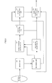
- FIG. 1 is a schematic view of the first embodiment.
- the super-resolution processing is a method of photographing multiple images with displacement in sub-pixel level and synthesizing these images after canceling a deterioration factor of an optical system or the like of these images.
- the optical system images an optical image on an imaging unit 101.
- the image imaged on the imaging unit 101 is spatially discretized and sampled, and then is converted into an image signal so as to be recorded in a recording unit 105. Further, a timing at which the image is imaged by the imaging unit 101 is recorded in an imaging timing recording unit 107.
- a weight coefficient for the imaged image is calculated by a weight calculating unit 104 by utilizing the timing information obtained by the imaging timing recording unit 107.
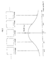
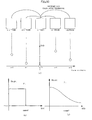
- FIG. 2 is an explanatory view showing an example of a weighting.
- a description will be given below of an example of the weighting calculation executed by the weight calculating unit 104 by using FIG. 2.
- FIG. 2 there is shown a weight coefficient ⁇ k with respect to the image in an order of respective frames.
- a method of weighting more heavily the frame which is closer to the n-th frame there can be considered a method of weighting a frame having a threshold value or less at a constant level, a method of changing a weight in a Gauss distribution manner (refer to FIG. 2) and the like.
- the weight coefficient obtained by this method can be expressed by ⁇ k in the following Expression 1, in the case of being expressed within an expression of the high-resolution processing method.
- reference symbol f(z) denotes an image high-resolution processing evaluation function
- reference symbol y k denotes a low-resolution image
- reference symbol A k denotes an image transformation matrix which considered an imaging system
- reference symbol z denotes a high-resolution image
- reference symbol ⁇ denotes a weight coefficient
- reference symbol g(z) denotes a constraint term which considered prior information such as smoothness of the image, color difference signal or the like.
- an image that becomes a basis is selected by a base image selecting unit 108 from the image data transmitted from the imaging unit 101 and recorded in the recording unit 105 .
- Position estimation of the base image selected by the base image selecting unit 108, and the other images is executed by a position estimating unit 102, and a result of position estimation is recorded in a position recording unit 103.
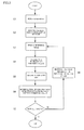
- S1 read one image which becomes a basis of the motion estimation and define this image as a base image.
- S2 generate an image sequence by deforming the base image with multiple motions.
- S3 read one reference image which is used for performing the motion estimation between the base image and itself.
- S4 calculate a plurality of similarity values between the image sequence obtained by deforming the base image with multiple motions and the reference image.
- S5 generate a discrete similarity map by utilizing a relation between the parameter of deformation motion and calculated similarity value.
- S6 obtain an extreme value of the continuous similarity values which are generated by interpolating the discrete similarity map generated in S5.
- the deformation motion with the extreme value becomes an estimated motion.
- S7 determine whether or not the motion estimation is performed for all reference images.
- S8 in the case that the motion estimation is not performed for all reference images, the step goes back to S3 by increasing the frame number of the reference image one by one, and continues a reading processing of the next image.
- the motion estimation is performed for all reference images which become an object, and the processing is finished if the result of determination in S7 comes to "Y".
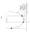
- FIG. 4 is an explanatory view showing an example in which the motion estimation is executed in accordance with parabola fitting.
- a vertical axis of FIG. 4 indicates a similarity, and the smaller the value is, the higher the similarity is.
- a black circle of FIG. 4 indicates a discrete similarity value, and a gray circle indicates an extreme value of the similarity.
- a curve connecting the discrete similarity values comes to an interpolated similarity. Turning back to the constitution of FIG.
- an image high-resolution processing for a base image is executed in a high-resolution processing unit 106, by using a weight coefficient obtained by the weight calculating unit 104, a position estimating amount between the images recorded in the position recording unit 103, image data recorded in the recording unit 105, and base image information obtained by the base image selecting unit 108.
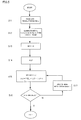
- S11 read n number of low-resolution images for using in the high-resolution image estimation (where, n ⁇ 1).
- S12 generate an initial high-resolution image by assuming one arbitrary image of multiple low-resolution images as a target frame and performing an interpolation processing. This step can be omitted as the case may be.
- S13 clarify a position relation between the images on the basis of the motion between the target frame and the other frames of images, which is previously determined in accordance with some kind or another motion estimating method.
- S14 obtain a point spread function (PSF) which considered an imaging characteristic such as an optical transfer function (OTF), a CCD aperture or the like.
- PSF point spread function
- the PSF utilizes, for example, a Gauss function.
- S15 minimize an evaluation function f(z) on the basis of the information of S13 and S14.
- f(z) is expressed by the following Expression 2.
- f z ⁇ k ⁇ ⁇ k - A k ⁇ z ⁇ 2 + ⁇ ⁇ g z
- reference symbol y k denotes a low-resolution image
- reference symbol z denotes a high-resolution image
- reference symbol A k denotes an image transformation matrix that represents an imaging system including motion between images, the PSF and the like.
- Reference symbol g(z) denotes a constraint term which considered prior information such as smoothness of the image, color difference signal or the like.
- Reference symbol ⁇ denotes a weight coefficient.
- steepest descent method is employed.
- S16 determine whether or not f(z) computed in S15 is minimized. In the case that f(z) is minimized, the high-resolution image z is obtained by finishing the process.
- S17 in the case that f (z) is not minimized yet, the step goes back to S13 by updating the high-resolution image z.
- FIG. 6 is a schematic view showing an example of a constitution at a time of executing the algorithm.
- the high-resolution processing init 106 described in FIG. 1 is constituted by an interpolation enlargement unit 61, a convolution integral unit 62, a PSF data holding unit 63, an image comparing unit 64, a multiplication unit 65, an assembling addition unit 66, an storage addition unit 67, an update image generating unit 68, an image storage unit 69, an iterative computation determining unit 610, and an iterative determination value holding unit 611.
- one arbitrary image data from image data of multiple frames is transmitted to the interpolation enlargement unit 61, and an interpolation enlargement of the image is executed here.
- an interpolation enlargement of the image is executed here.
- a method of the interpolation enlargement used here for example, there can be listed up a general bi-linear interpolation, a bi-cubic interpolation and the like.
- the interpolated and enlarged image is given to the convolution integral unit 62, and is integrated at a suitable coordinate position while taking into consideration the PSF data given from the PSF data holding unit 63 and the motion of per each of the multiple frames obtained by the motion estimating unit.
- the interpolated and enlarged image data is simultaneously transmitted to the image storage unit 69, and is stored here.
- the convolution computed image data is transmitted to the image comparing unit 64, and is compared with the photographed image given from the imaging unit.
- a compared residual error is transmitted to the multiplication unit 65, and is multiplied by the value per each of the pixels of the PSF data given from the PSF data holding unit 63.
- the result of computation is transmitted to the assembling addition unit 66, and is put at the corresponding coordinate position.
- the image data from the multiplication unit 65 is deviated little by little in the coordinate position while keeping the overlap, the overlapped portion is added.
- the data is transmitted to the storage addition unit 67.
- the storage addition unit 67 stores the data which is sequentially transmitted until the frame number of processing is finished, and sequentially adds the respective frame of image data in correspondence to the estimated motion.
- the added image data is transmitted to the update image generating unit 68.
- the image data stored in the image storage unit 69 is simultaneously given to the update image generating unit 68, and the update image data is generated by adding these two image data after weighting.
- the generated update image data is given to the iterative computation determining unit 610, and it is determined whether or not the computation is iterated on the basis of the iterative determining value given from the iterative determination value holding unit 611.
- the data is transmitted to the convolution integral unit 62 and the series of processing are iterated, and in the case that the computation is not iterated, the generated image data is output.
- the image output from the iterative computation determining unit 610 comes to the higher resolution image than the photographed image, by executing the series of processing mentioned above. Further, since it is necessary to execute a calculation at a suitable coordinate position at a time of the convolution integral, in the PSF data held by the PSF data holding unit 63, the constitution is made such that the data is given from the weight calculating unit 104.
- FIGs. 1 to 6 can construct the invention of the high-resolution processing method of image.
- the high-resolution processing method of image constituted by "optical imaging step of imaging an image of a subject” executed by the optical system, “step of discretizing and sampling said image imaged optically spatially, and then converting it into an image signal" executed by the imaging unit 101, "time relation memory step of storing a relative time relation between images of multiple frames that are sampled” executed by the recording unit 105, "base image determining step of determining a base image that becomes a basis from said images of multiple frames” executed by a base image selecting unit 108, "weighted-information generating step of generating weighted-information that corresponds to a time relation with said base image determined by said base image determining means per each of said multiple frames by using said relative time relation stored in the time relation memory means" executed by the weight calculating unit
- FIG. 7 is a schematic view showing a constitution of the second embodiment in accordance with the present invention.
- An optical system images an optical image on an imaging unit 201, and the imaged image is spatially discretized and sampled, and is converted into an image signal so as to be recorded in a recording unit 205.
- the image data recorded in the recording unit 205 selects a base image in a base image selecting unit 207.
- a position estimation between the base image and the other images is executed by a position estimating unit 202, and is recorded in a position recording unit 203. Details of an algorithm of the motion estimation is the same as that used in the first embodiment.
- a weight coefficient for the imaged image is calculated by a weight calculating unit 204 by utilizing the position estimation information recorded in the positionrecordingunit 203.
- the position estimating unit 202 serves as a means for determining a relative position relation between the sampled images of multiple frames in a higher resolution than a pixel spacing.
- FIG. 8 is an explanatory view showing an example of a weighting calculation calculated by the weight calculating unit 204.
- a description will be given of an example of the weighting calculation executed by the weight calculating unit 204 by using FIG. 8.
- the weighting is executed in such a manner as to enhance the influence of the low-resolution image sampled with dispersion in the sub-pixel unit, and is used for the image high-resolution processing.
- the following methods can be considered. It is assumed that the image similar to the dispersion +0.25[pixel] is intended to be used in the low-resolution image coordinate as shown in FIG. 8. In this case, it is preferable to employ an image photographed by a black circle, rather than an image photographed at a gray circle position. In this case, there is specifically executed a method of determining a distance from a position deviated at +0.25[pixel] to a position of the photographed pixel so as to weight the one having the smaller distance.
- the weight coefficient determined by this method can be expressed by ⁇ k in the following Expression 3, in the case of being expressed within an expression of the high-resolution processing method.
- f z ⁇ k k ⁇ ⁇ ⁇ k - A k ⁇ z ⁇ 2 + ⁇ ⁇ g z
- reference symbol f(z) denotes an image high-resolution processing evaluation function
- reference symbol y k denotes a low-resolution image
- reference symbol A k denotes an image transformation matrix that considered an imaging system
- reference symbol z denotes a high-resolution image
- reference symbol ⁇ denotes a weight coefficient
- reference symbol g(z) denotes a constraint term which considered prior information such as smoothness of the image, color difference signal or the like.
- an image high-resolution processing of the base image is executed in the high-resolution processing unit 206, by using the weight coefficient obtained by the weight calculating unit 204 of FIG. 7, the position estimation amount between the images recorded in the position recording unit 203, the image data recorded in the recording unit 205, and the base image information obtained by the base image selecting unit 207. Details of the image high-resolution processing is the same as that used in the embodiment 1.
- FIGs. 7 and 8 can construct the invention of the high-resolution processing method of image.
- the high-resolution processing method of image constituted by "optical imaging step of imaging an image of a subject” executed by the optical system, "step of discretizing and sampling said image imaged optically spatially, and then converting it into an image signal" executed by the imaging unit 201, "position relation calculating step of obtaining a relative position relation between said images of multiple frames that are sampled in a higher resolution than a pixel spacing that was sampled” executed by the position estimating unit 202, "base image determining step of determining a base image that becomes a basis from said images of multiple frames” executed by a base image selecting unit 207, "weighted-information generating step of generating weighted-information that corresponds to a position relation with said base image per each of said multiple frames by using said relative position relation calculated by said position
- FIG. 9 is a schematic view showing a constitution of the third embodiment in accordance with the present invention.
- An optical system images an optical image on an imaging unit 301, and the imaged image is spatially discretized and sampled, and is converted into an image signal so as to be recorded in a recording unit 305.
- the image data recorded in the recording unit 305 selects a base image in a base image selecting unit 307.
- a position estimation between the base image and the other images is executed by an imaged position estimating unit 302, and is recorded in a position recording unit 303.
- the imaging position estimating unit 302 serves as a means for obtaining a relative position relation between the sampled images of multiple frames in a higher resolution than a pixel spacing.
- a weight coefficient for the imaged image is calculated by a weight calculating unit 304 by utilizing the position estimation information recorded in the position recording unit 303 and the image data recorded by the recording unit 305.
- FIG. 10 is an explanatory view showing an example of a weighting calculation executed by the weight calculating unit 304.
- the method of calculating the weight by the weight calculating unit 304 is executed as follows. In the case of performing high-resolution processing of n-th frame, motions between n-th frame and the other frames are estimated. At this time, the higher the motion estimating precision is, the more heavily the weighting is executed at a time of the image high-resolution processing.
- a non-similarity evaluation value SSD, SAD or the like
- the method of weighting on the basis of the non-similarity evaluation value includes a method of weighting constantly the non-similarity equal to or less than a threshold value (case 1 of FIG. 1.0 (b)), a method of changing the weight in a Gauss distribution manner (case 2 of FIG. 10(c)) and the like.
- the weight coefficient obtained in accordance with this method can be expressed by ⁇ k in the following Expression 4, in the case of being expressed within an expression of the high-resolution processing method.
- f z ⁇ k ⁇ k ⁇ ⁇ ⁇ k - A k ⁇ z ⁇ 2 + ⁇ ⁇ g z
- reference symbol f(z) denotes an image high-resolution processing evaluation function
- reference symbol y k denotes a low-resolution image
- reference symbol A k denotes an image transformation matrix that considered an imaging system
- reference symbol z denotes a high-resolution image
- reference symbol ⁇ denotes a weight coefficient
- reference symbol g(z) denotes a constraint term which considered prior information such as smoothness of the image, color difference signal or the like.
- an image high-resolution processing of the base image is executed in the high-resolution processing unit 306, by using the weight coefficient obtained by the weight calculating unit 304 in FIG. 9, the position estimation amount between the images recorded in the position recording unit 303, the image data recorded in the recording unit 305, and the base image information obtained by the base image selecting unit 307. Details of the image high-resolution processing is the same as that used in the first embodiment.
- FIGs . 9 and 10 can construct the invention of the high-resolution processing method of image.
- the high-resolution processing method of image constituted by "optical imaging step of imaging an image of a subject” executed by the optical system, "step of discretizing and sampling said image imaged optically spatially, and then converting it into an image signal" executed by the imaging unit 301, "position relation calculating step of obtaining a relative position relation between said images of multiple frames that are sampled in a higher resolution than a pixel spacing that was sampled” executed by the imaging position estimating unit 302, "base image determining step of determining a base image that becomes a basis from said images of multiple frames” executed by the base image selecting unit 307, "similarity calculating step of calculating a similarity between said base image and said image of per each of said multiple frames by using said relative position relation” and "weighted-information generating step
- the constitutions described in FIGs . 1, 7 and 9 construct the invention of the high-resolution processing method of image in common.
- the invention of the high-resolution processing method of image constituted by "optical imaging step of imaging an image of a subject" executed by the optical system, "step of discretizing and sampling said image imaged optically spatially, and then converting it into an image signal" executed by the imaging units 101, 201 and 301, "weighted-information generating step of generating weighted-information of said images of multiple frames that are sampled” executed by the weight calculating units 104, 204 and 304, and "high-resolution processing step of generating ahigh-resolution image by using said weighted-information” executed by the high-resolution processing units 106, 206 and 306.
- the imaging device and the high-resolution processing method of image which precisely generate the high-resolution image by using the image data with a little number of the pixels.
- the imaging device and the high-resolution processing method of image in accordance with the present invention it is possible to improve the reduction of the precision of the high-resolution image estimating processing caused by the great change between multiple low-resolution images used for processing by the photographing status so as to improve the estimating precision of the high-resolution image.
- Patent Document 1 Japanese Patent Publication No. H10-69537
Landscapes
- Engineering & Computer Science (AREA)
- Multimedia (AREA)
- Signal Processing (AREA)
- Computing Systems (AREA)
- Theoretical Computer Science (AREA)
- Image Processing (AREA)
- Studio Devices (AREA)
- Studio Circuits (AREA)
- Editing Of Facsimile Originals (AREA)
- Transforming Light Signals Into Electric Signals (AREA)
Applications Claiming Priority (2)
| Application Number | Priority Date | Filing Date | Title |
|---|---|---|---|
| JP2004330253A JP4151793B2 (ja) | 2004-11-15 | 2004-11-15 | 撮像装置および画像の高解像化方法 |
| PCT/JP2005/021312 WO2006052029A1 (ja) | 2004-11-15 | 2005-11-15 | 撮像装置および画像の高解像化方法 |
Publications (1)
| Publication Number | Publication Date |
|---|---|
| EP1816856A1 true EP1816856A1 (en) | 2007-08-08 |
Family
ID=36336681
Family Applications (1)
| Application Number | Title | Priority Date | Filing Date |
|---|---|---|---|
| EP05804077A Withdrawn EP1816856A1 (en) | 2004-11-15 | 2005-11-15 | Imaging device and image resolution increase method |
Country Status (4)
| Country | Link |
|---|---|
| US (1) | US7990428B2 (enExample) |
| EP (1) | EP1816856A1 (enExample) |
| JP (1) | JP4151793B2 (enExample) |
| WO (1) | WO2006052029A1 (enExample) |
Cited By (1)
| Publication number | Priority date | Publication date | Assignee | Title |
|---|---|---|---|---|
| CN102377935A (zh) * | 2010-08-20 | 2012-03-14 | 华晶科技股份有限公司 | 超解析影像的产生方法 |
Families Citing this family (23)
| Publication number | Priority date | Publication date | Assignee | Title |
|---|---|---|---|---|
| JP4851240B2 (ja) * | 2006-06-05 | 2012-01-11 | 株式会社トプコン | 画像処理装置及びその処理方法 |
| JP4809134B2 (ja) * | 2006-06-05 | 2011-11-09 | 株式会社トプコン | 画像処理装置及びその処理方法 |
| JP4851239B2 (ja) * | 2006-06-05 | 2012-01-11 | 株式会社トプコン | 画像処理装置及びその処理方法 |
| JP4813263B2 (ja) * | 2006-06-05 | 2011-11-09 | 株式会社トプコン | 画像処理装置及びその処理方法 |
| JP5055571B2 (ja) * | 2006-09-14 | 2012-10-24 | 株式会社ニコン | 画像処理装置、電子カメラ、および画像処理プログラム |
| WO2008032442A1 (fr) * | 2006-09-14 | 2008-03-20 | Nikon Corporation | Dispositif de traitement d'images, caméra électronique et programme de traitement d'images |
| JP4814840B2 (ja) | 2007-05-23 | 2011-11-16 | オリンパス株式会社 | 画像処理装置又は画像処理プログラム |
| JP5098081B2 (ja) | 2007-07-19 | 2012-12-12 | オリンパス株式会社 | 画像処理方法および画像処理装置 |
| JP5076755B2 (ja) * | 2007-09-07 | 2012-11-21 | ソニー株式会社 | 画像処理装置、および画像処理方法、並びにコンピュータ・プログラム |
| SG154342A1 (en) * | 2008-01-08 | 2009-08-28 | Opulent Electronics Internat P | Insulated metal substrate fabrication |
| US8570386B2 (en) * | 2008-12-31 | 2013-10-29 | Stmicroelectronics S.R.L. | Method of merging images and relative method of generating an output image of enhanced quality |
| US8995793B1 (en) * | 2009-10-09 | 2015-03-31 | Lockheed Martin Corporation | Moving object super-resolution systems and methods |
| US20120044389A1 (en) * | 2010-08-20 | 2012-02-23 | Altek Corporation | Method for generating super resolution image |
| TWI459325B (zh) * | 2011-05-13 | 2014-11-01 | Altek Corp | 數位影像處理裝置及其處理方法 |
| US9053557B2 (en) | 2011-12-02 | 2015-06-09 | Industrial Technology Research Institute | System and method for improving visual effect of a display device |
| JP2013130541A (ja) * | 2011-12-22 | 2013-07-04 | Tohto C-Tech Corp | 接着検査装置 |
| CN103379255B (zh) * | 2012-04-24 | 2017-06-06 | 华晶科技股份有限公司 | 影像处理装置及其处理方法 |
| EP2677733A3 (en) * | 2012-06-18 | 2015-12-09 | Sony Mobile Communications AB | Array camera imaging system and method |
| US9363438B2 (en) * | 2013-07-23 | 2016-06-07 | Michael BEN ISRAEL | Digital image processing |
| JP6230333B2 (ja) * | 2013-08-22 | 2017-11-15 | オリンパス株式会社 | 画像処理装置、画像処理方法およびプログラム |
| US9672608B2 (en) | 2013-08-22 | 2017-06-06 | Olympus Corporation | Image processing device, endoscope apparatus, image processing method, and program |
| KR102146560B1 (ko) * | 2014-02-17 | 2020-08-20 | 삼성전자주식회사 | 영상 보정 방법 및 장치 |
| WO2017086091A1 (ja) * | 2015-11-18 | 2017-05-26 | オリンパス株式会社 | 画像処理装置、画像処理方法およびプログラム |
Family Cites Families (7)
| Publication number | Priority date | Publication date | Assignee | Title |
|---|---|---|---|---|
| US5696848A (en) * | 1995-03-09 | 1997-12-09 | Eastman Kodak Company | System for creating a high resolution image from a sequence of lower resolution motion images |
| JP2828138B2 (ja) | 1996-08-28 | 1998-11-25 | 日本電気株式会社 | 画像合成方法及び画像合成装置 |
| JP4371457B2 (ja) | 1999-02-18 | 2009-11-25 | キヤノン株式会社 | 画像処理装置、方法及びコンピュータ読み取り可能な記憶媒体 |
| CA2289053C (en) * | 1998-11-10 | 2008-07-29 | Canon Kabushiki Kaisha | Image processing method and apparatus |
| US20030193567A1 (en) * | 2002-04-12 | 2003-10-16 | Hubel Paul M. | Digital camera media scanning methods, digital image processing methods, digital camera media scanning systems, and digital imaging systems |
| US7352919B2 (en) * | 2004-04-28 | 2008-04-01 | Seiko Epson Corporation | Method and system of generating a high-resolution image from a set of low-resolution images |
| JP4367264B2 (ja) * | 2004-07-12 | 2009-11-18 | セイコーエプソン株式会社 | 画像処理装置、画像処理方法、および、画像処理プログラム |
-
2004
- 2004-11-15 JP JP2004330253A patent/JP4151793B2/ja not_active Expired - Fee Related
-
2005
- 2005-11-15 EP EP05804077A patent/EP1816856A1/en not_active Withdrawn
- 2005-11-15 US US11/667,766 patent/US7990428B2/en not_active Expired - Fee Related
- 2005-11-15 WO PCT/JP2005/021312 patent/WO2006052029A1/ja not_active Ceased
Non-Patent Citations (1)
| Title |
|---|
| See references of WO2006052029A1 * |
Cited By (1)
| Publication number | Priority date | Publication date | Assignee | Title |
|---|---|---|---|---|
| CN102377935A (zh) * | 2010-08-20 | 2012-03-14 | 华晶科技股份有限公司 | 超解析影像的产生方法 |
Also Published As
| Publication number | Publication date |
|---|---|
| WO2006052029A1 (ja) | 2006-05-18 |
| US7990428B2 (en) | 2011-08-02 |
| JP2006140886A (ja) | 2006-06-01 |
| US20100253796A1 (en) | 2010-10-07 |
| JP4151793B2 (ja) | 2008-09-17 |
Similar Documents
| Publication | Publication Date | Title |
|---|---|---|
| EP1816856A1 (en) | Imaging device and image resolution increase method | |
| US8306121B2 (en) | Method and apparatus for super-resolution of images | |
| JP4968259B2 (ja) | 画像高解像度化装置及び画像高解像度化方法並びにプログラム | |
| EP2688282B1 (en) | Image processing device, image processing method, and image processing program | |
| US7978234B2 (en) | Image acquisition apparatus, resolution enhancing method, and recording medium | |
| KR100929085B1 (ko) | 화상 처리 장치, 화상 처리 방법 및 컴퓨터 프로그램 기록매체 | |
| EP2688288B1 (en) | Image compositing device, image compositing method, image compositing program, and recording medium | |
| EP1591959A1 (en) | Method of generating high-resolution image, digital image editing tool and computer readable medium | |
| EP2613290B1 (en) | Image processing device, image processing method, and image processing program | |
| US20040260662A1 (en) | Neural network trained with spatial errors | |
| JP5500163B2 (ja) | 画像処理システム、画像処理方法および画像処理プログラム | |
| US20040086193A1 (en) | Video image synthesis method, video image synthesizer, image processing method, image processor, and programs for executing the synthesis method and processing method | |
| JP2008098803A (ja) | 高解像度化装置および方法 | |
| US20070177027A1 (en) | Imaging system and process for rendering the resolution of images high | |
| JP2011060282A (ja) | 動き領域の非線形スムージングを用いた動き検出方法およびシステム | |
| CN113536971A (zh) | 一种基于增量学习的目标检测方法 | |
| EP1816854A1 (en) | Image pickup device, image pickup system and image photographing method | |
| JP5566199B2 (ja) | 画像処理装置およびその制御方法、並びにプログラム | |
| WO2005122554A1 (ja) | 撮像装置 | |
| US8736720B2 (en) | Image processing device for correcting image colors and image processing program | |
| KR102057395B1 (ko) | 기계학습 기반 비디오 보외법을 이용한 영상 생성 방법 | |
| JP2009065283A (ja) | 画像ぶれ補正装置 | |
| CN103618904A (zh) | 基于像素的运动估计方法及装置 | |
| Sangi et al. | Motion analysis using frame differences with spatial gradient measures | |
| KR102651383B1 (ko) | 비디오 화질 개선을 위한 픽셀 볼륨 기반의 기계학습 방법 및 이를 이용하는 장치 |
Legal Events
| Date | Code | Title | Description |
|---|---|---|---|
| PUAI | Public reference made under article 153(3) epc to a published international application that has entered the european phase |
Free format text: ORIGINAL CODE: 0009012 |
|
| 17P | Request for examination filed |
Effective date: 20070611 |
|
| AK | Designated contracting states |
Kind code of ref document: A1 Designated state(s): AT BE BG CH CY CZ DE DK EE ES FI FR GB GR HU IE IS IT LI LT LU LV MC NL PL PT RO SE SI SK TR |
|
| DAX | Request for extension of the european patent (deleted) | ||
| STAA | Information on the status of an ep patent application or granted ep patent |
Free format text: STATUS: THE APPLICATION IS DEEMED TO BE WITHDRAWN |
|
| 18D | Application deemed to be withdrawn |
Effective date: 20100601 |